1. Introduction
Post-fire assessment of reinforced concrete (RC) members remains a major challenge in structural engineering, particularly in existing buildings where the extent of mechanical degradation is difficult to quantify. Although concrete is generally regarded as a fire-resistant material, elevated temperatures induce dehydration of the cement paste, progressive microcracking, stiffness loss, and, in severe cases, explosive spalling, all of which substantially reduce the residual load-bearing capacity of RC elements [
1,
2,
3,
4]. Real fire events in underground parking structures have shown that severe thermal exposure may lead to extensive concrete spalling and critical damage in RC structural members [
5]. The spatial distribution of thermal damage is typically heterogeneous: depending on fire duration, ventilation, and fuel load, columns may exhibit gradients of degradation along their height or asymmetrically across their cross-section. Recent investigations have highlighted the potentially severe thermal exposure conditions that may develop in confined parking environments subjected to vehicle fires [
6]. This complexity is rarely captured adequately by traditional assessment methods, which rely mainly on visual inspection, superficial hardness tests, or limited destructive sampling, procedures that often fail to reveal internal defects or accurately characterise the residual stiffness of fire-exposed RC components [
7]. Recent review studies on fire-damaged RC structures have further highlighted the need for more reliable and integrated post-fire assessment methodologies capable of supporting engineering decision-making in real structures [
3,
8,
9].
In response to these limitations, non-destructive testing (NDT) techniques have become increasingly important for post-fire structural safety evaluations. Among them, elastic-wave-based methods (sonic or ultrasonic) have proven highly effective in fire-damage assessment, as wave propagation velocities are sensitive to internal cracking, porosity changes, and thermal degradation of concrete [
10,
11]. Early investigations demonstrated the potential of sonic testing (ST) to diagnose damage in fire-affected concrete structures, and subsequent studies have refined the interpretation of P- and S-wave measurements to estimate dynamic Young’s modulus in situ [
12,
13]. These techniques are particularly relevant for post-fire diagnosis because they enable the evaluation of stiffness variations along the height of a column, allowing the identification of degradation patterns commonly found after real fire incidents. Recent post-fire investigations have also demonstrated the growing relevance of combined inspection and non-destructive evaluation strategies for RC structures affected by real fire scenarios [
14,
15].
Other non-destructive techniques, such as active thermography with microwave or induction excitation, have also been proposed for the evaluation of RC structures, where external energy sources are used to induce thermal responses in the material, enabling the detection of reinforcement layout and near-surface defects [
16]. However, these approaches are primarily sensitive to local thermal and physical properties, whereas the methodology proposed in this work focuses on the global dynamic response and effective stiffness of structural elements, providing complementary information for post-fire assessment.
Parallel to wave-based techniques, vibration-based approaches, specifically Experimental Modal Analysis (EMA), have become powerful tools in structural health monitoring (SHM) due to their high sensitivity to stiffness changes [
17,
18,
19,
20]. Changes in natural frequencies and mode shapes have long been recognised as indicators of damage in concrete and composite structures, even when deterioration is not visible externally [
19,
20]. Recent research has extended the use of EMA to RC elements exposed to fire, confirming that modal parameters provide meaningful insight into global stiffness loss and potential internal discontinuities [
21].
In this context, the combined use of EMA and ST offers a significant advantage for post-fire assessment. While EMA provides global indicators of stiffness loss through changes in modal parameters, ST enables the localisation and quantification of material degradation along the structural element. This complementarity allows a more comprehensive evaluation of fire-induced damage than the use of either technique independently.
Despite the recognised potential of this combined approach, the joint use of global vibration-based indicators obtained through EMA and local stiffness estimates derived from ST for the in situ assessment of fire-damaged RC columns remains largely unexplored. Although previous studies have investigated post-fire damage in reinforced concrete structures and parking garage fire scenarios using isolated inspection or monitoring techniques [
14,
15], the integration of experimental dynamic measurements with numerical validation frameworks under real fire conditions is still limited in existing literature. While numerical model updating using finite element (FE) simulations is widely employed to validate modal parameters and assess damage sensitivity [
22], its application to dynamic NDT methodologies for fire-damaged concrete structures remains scarce. Existing studies typically focus on laboratory specimens or simplified structural elements, leaving open questions regarding the reliability and operational applicability of dynamic NDT techniques in full-scale, in situ post-fire investigations [
7]. This gap in the literature underscores the novelty and practical relevance of the hybrid EMA–ST methodology proposed in this work.
This work addresses this gap by developing, validating, and applying a combined dynamic NDT methodology that integrates EMA and ST for the structural health assessment of RC columns damaged by real building fires. The proposed methodology is validated through a three-step strategy. First, an experimental cross-validation is carried out on undamaged reference columns with identical geometry and boundary conditions to assess the repeatability and robustness of the EMA and ST measurements under in situ conditions. Second, a numerical validation based on FE model updating is performed on a reference column to verify the consistency between experimentally identified modal parameters and stiffness distributions derived from ST. Finally, the validated experimental–numerical framework is applied to a fire-damaged column with the same geometry and boundary conditions, demonstrating the capability of the methodology to reproduce the dynamic response associated with real fire-induced stiffness degradation.
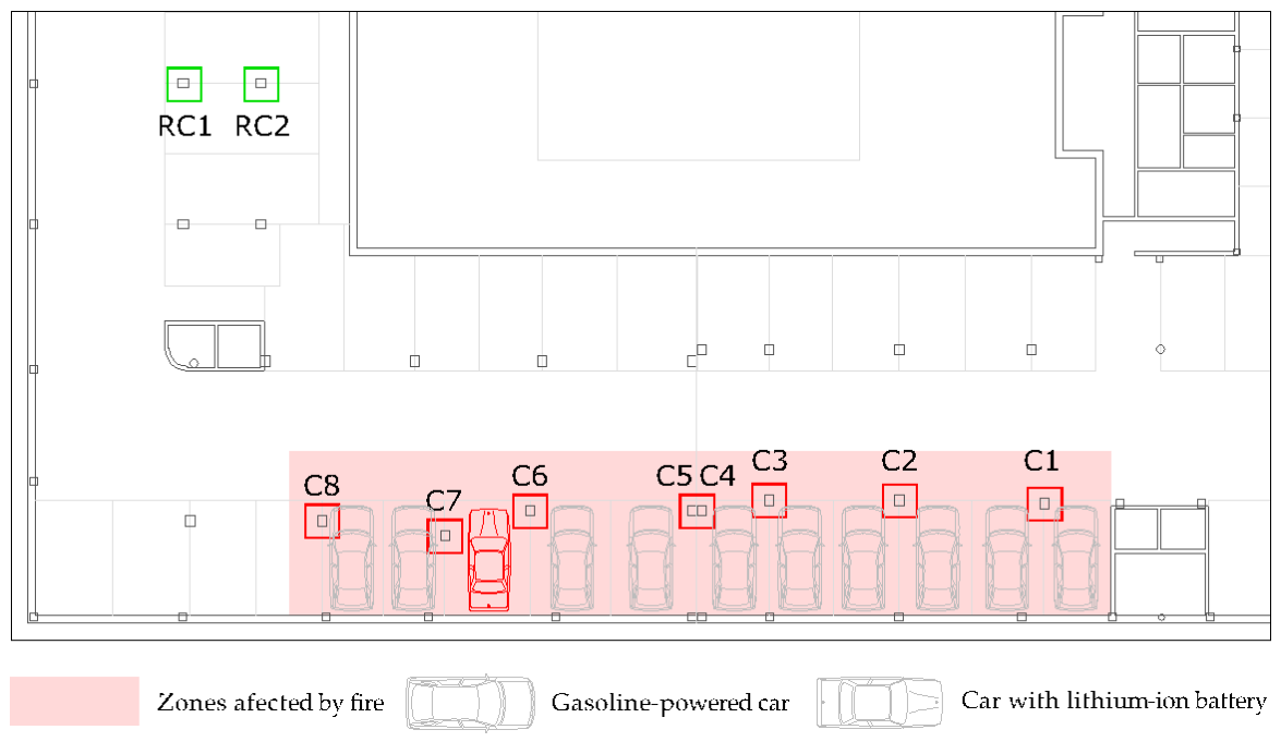
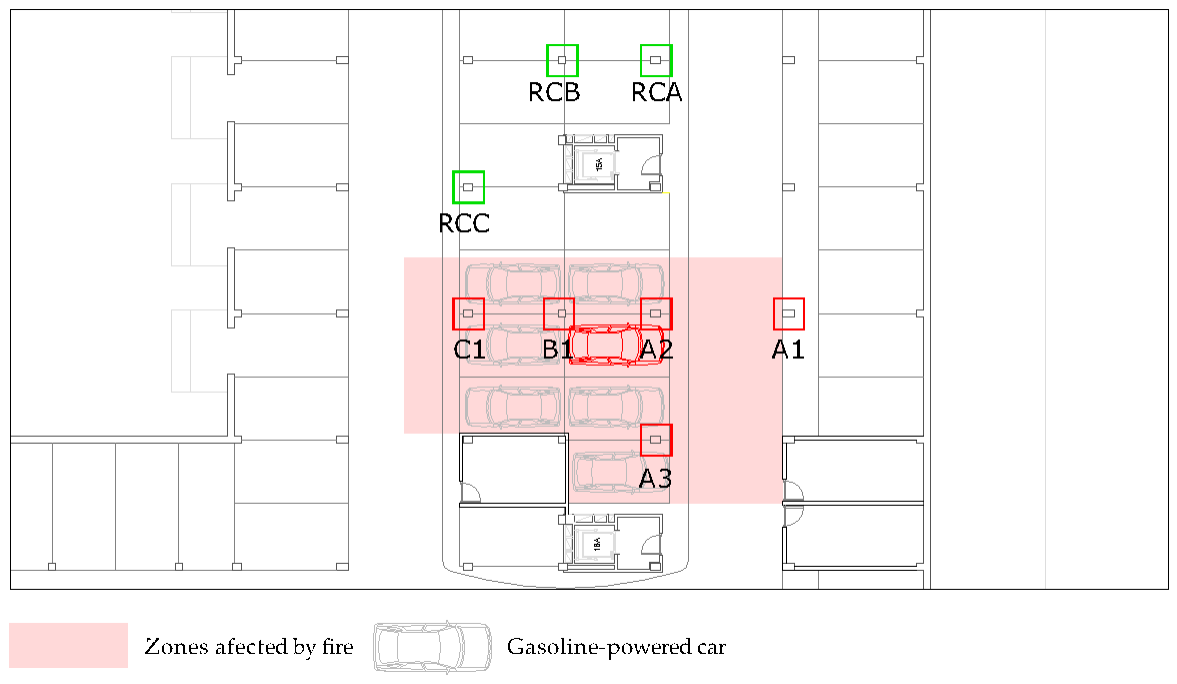
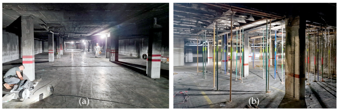
After validation, the methodology is applied to two real fire events affecting basement RC columns in residential buildings in Seville (Spain). These cases, one exhibiting severe fire exposure and extensive mechanical degradation, and the other showing more moderate temperature effects, provide an opportunity to analyse the diagnostic range of the method across different levels of structural damage. In both scenarios, the joint interpretation of modal indicators, dynamic Young’s modulus profiles, and damage patterns demonstrates the capacity of the methodology to quantify stiffness loss, identify internal discontinuities, and discriminate between severely and moderately affected elements (
Figure 1).
The objectives of this work are therefore fourfold: (i) to formulate a dynamic NDT-based methodology combining EMA and ST for post-fire assessment of RC columns; (ii) to validate the methodology using numerical and experimental benchmarks; (iii) to apply the method to two real building fires to assess its diagnostic capabilities; and (iv) to evaluate its potential as a practical decision-making tool for structural engineers. The results show that the proposed approach provides an effective and cost-efficient framework for supporting post-fire interventions and avoiding unnecessary strengthening measures. It should be noted that the study is based on a limited number of in situ tested columns, and therefore the results are intended to validate the proposed methodology under real conditions rather than to establish statistically generalizable conclusions.
The remainder of this paper is organised as follows.
Section 2 describes the proposed NDT methodology, detailing the principles of EMA and ST, as well as the experimental procedures adopted for in situ measurements.
Section 3 presents the validation of the methodology, including numerical validation through FE model updating and experimental cross-validation using reference columns.
Section 4 applies the validated methodology to two real fire-damaged basement case studies, presenting and discussing the results obtained from EMA and ST.
Section 5 discusses the main findings, highlighting damage patterns, methodological strengths, and practical implications for post-fire structural assessment. Finally,
Section 6 summarises the main conclusions of the study and outlines perspectives for future research.
2. Materials and Methods
This section presents the proposed NDT methodology for the post-fire assessment of RC columns. The approach is based on the combined use of EMA and ST, two dynamic techniques that provide complementary information on structural stiffness and material degradation. EMA is employed to characterise the global dynamic behaviour of the column, allowing stiffness loss to be inferred from changes in natural frequencies and mode shapes, while ST is used to estimate local variations in the dynamic elastic properties of concrete through elastic wave propagation.
The methodology is conceived for in situ application and relies on comparative analysis between fire-exposed columns and reference elements with similar geometry and boundary conditions. By integrating global indicators derived from vibration measurements with local estimates of dynamic Young’s modulus, the proposed approach enables both the detection and localisation of fire-induced damage.
All experimental campaigns (EMA and ST) were carried out using the same instrumentation and data acquisition system. The setup consisted of a multi-channel data acquisition unit (SIRIUS® XHS, Dewesoft, Trbovlje, Slovenia, up to 15 MS/s), triaxial IEPE accelerometers (MMF KS903B10, MMF, Strausberg, Germany, 10 mV/g) with a frequency range of 0.15–22,000 Hz in the main axes, and an instrumented impact hammer (YMC IH-02PE, YMC Piezotronics Inc., Hamamatsu, Japan) with a sensitivity of 2.5 mV/N and a resonant frequency of approximately 55 kHz. A nylon hammer tip was used during experimental campaigns to provide suitable frequency content for the modal excitation of the RC columns. The accelerometers were attached to the concrete surface using a removable plasticine-based coupling material, ensuring adequate mechanical coupling while avoiding damage to the structural elements during the in situ measurements. All sensors were factory-calibrated and operated within their nominal measurement ranges during testing.
The experimental procedures described in the following subsections were applied consistently during the validation phase and the real case studies presented later in this work.
2.1. Experimental Modal Analysis (EMA)
2.1.1. Fundamentals of EMA
EMA is a vibration-based NDT technique aimed at identifying the dynamic properties of a structure, including its natural frequencies, mode shapes, and damping characteristics. For linear elastic systems, these modal parameters are governed by the mass and stiffness distribution of the structure. As a consequence, any degradation of material properties or structural integrity, such as the stiffness loss induced by fire exposure, results in measurable changes in the dynamic response, particularly in the form of reduced natural frequencies and altered vibration modes [
18,
19,
20].
In RC columns, fire exposure leads to a combination of microcracking, degradation of the cement matrix, and potential loss of bond between concrete and reinforcement. These damage mechanisms reduce the effective flexural stiffness of the column and may introduce internal discontinuities. EMA is especially suitable for detecting such effects, as the lower-order bending modes of slender structural elements are highly sensitive to stiffness variations while being relatively insensitive to local mass changes [
20].
From a structural dynamics perspective, the natural frequencies
of a structural system can be expressed, in simplified form, as follows:
where
represents the global stiffness of the system and
its mass. Since the mass of RC columns remains essentially unchanged after fire exposure, reductions in measured natural frequencies can be directly associated with stiffness loss. This property makes EMA a robust indicator for post-fire damage assessment, particularly when comparative analyses are performed between fire-exposed and reference columns with similar geometry and boundary conditions [
23].
Beyond frequency shifts, EMA provides valuable qualitative information through the identification of mode shapes. Fire-induced damage often manifests as distorted, poorly defined, or asymmetric modal shapes, reflecting non-uniform stiffness degradation or internal cracking. Such modal irregularities have been widely recognised as indicators of structural damage and loss of mechanical continuity in concrete elements [
18].
2.1.2. Experimental Setup and Testing Procedure
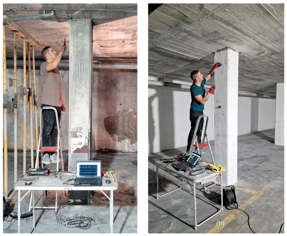
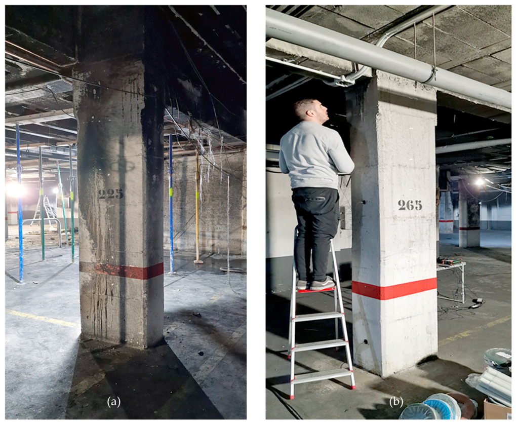
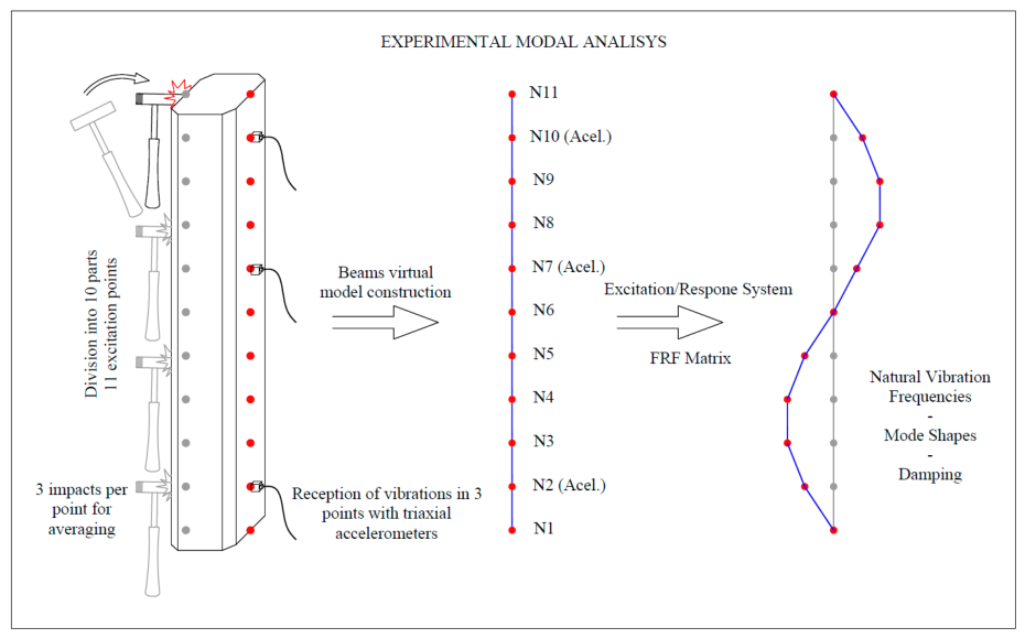
The experimental setup described above was used for modal identification through impact testing (
Figure 2). To characterise the dynamic behaviour along the height of the column, each element was discretised into a set of equally spaced impact points from the base to the top. At each location, three impacts were applied in order to improve the signal-to-noise ratio and ensure repeatability of the measured response. The resulting signals were subsequently processed and compared to verify the consistency of the identified modal parameters. Accelerometers were positioned at eleven fixed locations on the column to record the response in the principal orthogonal directions (X and Y), corresponding to the main bending planes of the element.
Force and acceleration signals were recorded simultaneously using a multi-channel data acquisition system, with a sampling frequency sufficiently high to capture the first several vibration modes relevant for damage assessment. Care was taken to maintain consistent boundary conditions and sensor placement across all tested columns to ensure comparability of the results.
2.1.3. Signal Processing and Modal Identification
The recorded time-domain force and acceleration signals were processed to obtain Frequency Response Functions (FRFs), defined as the ratio between the measured acceleration response and the applied force in the frequency domain. A band-pass filter between 0.05 kHz and 1 kHz was applied during signal processing in order to reduce environmental noise and improve the identification of the resonance peaks associated with the vibration modes of the columns. Resonance frequencies were identified as peaks in the magnitude of the FRFs, corresponding to the natural vibration modes of the column.
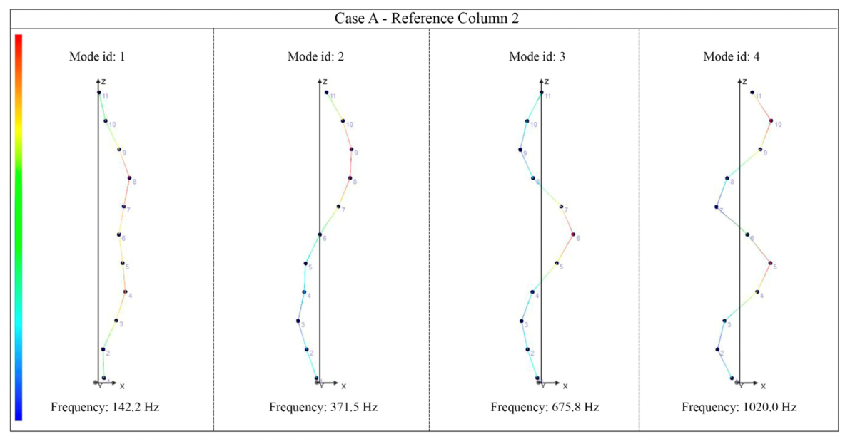
Modal identification was carried out using peak-picking techniques supported by coherence analysis to ensure the reliability of the identified modes. The analysis focused on the first four bending modes in each principal direction, as these modes exhibit the highest sensitivity to stiffness degradation in RC columns. Natural frequencies were extracted for all identified modes and compared between reference columns and fire-exposed columns.
In addition to frequency shifts, qualitative assessment of the identified mode shapes was performed. Modes presenting irregular shapes, loss of symmetry, or poor spatial definition were interpreted as indicators of non-uniform stiffness degradation or internal discontinuities caused by fire exposure. Such qualitative information complements the quantitative frequency-based indicators and enhances the diagnostic capability of the method [
18].
2.2. Sonic Testing (ST)
2.2.1. Fundamentals of Elastic Wave Propagation in Concrete
ST is a non-destructive technique based on the propagation of elastic waves through a solid medium. In concrete, the velocities of elastic waves are strongly influenced by the material’s elastic properties, density, and internal condition. Fire exposure typically induces microcracking, increased porosity, and degradation of the cement matrix, which lead to a reduction in wave propagation velocities. For this reason, sonic and ultrasonic methods have long been recognised as effective tools for assessing fire-induced damage in concrete structures [
10,
11].
In an isotropic elastic material, two main types of body waves can propagate: compression waves (P-waves) and shear waves (S-waves). The velocities of these waves, and , are related to the elastic constants of the material and its density. Although concrete is a heterogeneous material, elastic wave theory provides a sufficiently accurate framework for estimating dynamic elastic parameters under in situ conditions when comparative analyses are performed.
2.2.2. Experimental Setup and Testing Procedure
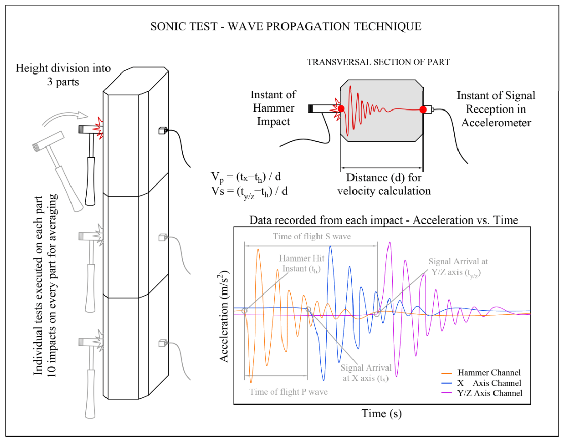
The same instrumentation was employed for ST measurements. The hammer force signal was used as a time reference to determine the instant of wave generation (
Figure 3). For each measurement location, eleven impacts were applied to ensure repeatability and improve signal quality. The reported wave velocities and derived elastic parameters correspond to the average values obtained from the repeated measurements. The arrival times of the compression (P) waves and shear (S) waves were identified from the acceleration signals recorded along different axes. The distance between the impact point and the accelerometer was measured accurately, allowing wave velocities to be computed as the ratio between travelled distance and measured travel time.
Measurements were performed at multiple heights along each column, typically at lower, intermediate, and upper zones. This configuration enabled the identification of vertical gradients in material degradation, which are frequently observed in fire-damaged columns due to the non-uniform temperature distribution during the fire event.
2.2.3. Estimation of Dynamic Elastic Parameters
From the measured wave velocities, dynamic elastic parameters of the concrete were estimated using classical elastic wave relationships [
10,
11,
12]. Assuming linear elastic behaviour, Poisson’s ratio
, shear modulus
, and dynamic Young’s modulus
can be expressed as:
where
and
are the compression and shear wave velocities, respectively, and
is the material density. Density values were obtained from construction documentation and verified using unaffected reference columns, following the expected values associated with the structural typology and standard construction quality control procedures. Given that density variations in reinforced concrete are generally limited compared to stiffness changes induced by fire exposure, this approach provides sufficient accuracy for the comparative analysis performed.
The dynamic Young’s modulus values obtained from ST were analysed both in absolute terms and relative to reference columns. Reductions in were interpreted as indicators of fire-induced material degradation. In addition, variations of along the column height were examined to identify spatial damage patterns, such as increased degradation in zones subjected to higher thermal exposure.
It should be noted that the elastic parameters derived from ST correspond to dynamic properties of the material. While these values may differ from static elastic moduli, they provide consistent and sensitive indicators of relative stiffness loss, particularly when used for comparative post-fire assessment [
10].
2.3. Complementarity of EMA and ST
The selected experimental configuration combines global and local non-destructive techniques to capture complementary aspects of structural behaviour. EMA is used to assess the global dynamic response of the column, which is directly related to its overall stiffness and boundary conditions, whereas sonic testing provides localised information on material degradation along the height of the element. This combination is particularly advantageous for post-fire assessment, where damage is often heterogeneous, non-visible, and unevenly distributed along the element. Compared to alternative techniques focused on the characterisation of reinforcement behaviour, such as magnetic-based methods, the proposed approach is better suited for reinforced concrete elements affected by fire, where damage is primarily associated with stiffness loss in the concrete matrix and its spatial distribution.
EMA provides a global dynamic perspective of the column, capturing the integrated effect of stiffness degradation, boundary conditions, and possible internal discontinuities through changes in natural frequencies and mode shapes. As a result, EMA is especially effective for identifying whether a column has experienced a significant loss of global stiffness and for discriminating between affected and unaffected elements within a group of structurally similar columns. However, due to its global nature, EMA alone does not allow precise localisation of material degradation along the column height.
In contrast, ST provides local information on material properties, allowing the estimation of dynamic elastic parameters at specific locations. By measuring elastic wave velocities at different heights, ST makes it possible to identify vertical gradients of stiffness loss and zones of higher thermal degradation, which are commonly observed in fire-damaged columns. Nevertheless, ST by itself does not account for the influence of boundary conditions or the global structural behaviour of the element.
By integrating both techniques, the proposed methodology combines the strengths of each approach while mitigating their individual limitations. Reductions in natural frequencies identified by EMA can be directly correlated with decreases in dynamic Young’s modulus obtained from ST, providing a consistent interpretation of stiffness loss at both global and local scales. Furthermore, discrepancies between modal behaviour and local elastic properties may reveal the presence of internal discontinuities or non-uniform damage patterns that would be difficult to detect using a single technique.
This combined interpretation constitutes the basis of the proposed diagnostic framework. EMA is used as a first-level indicator to identify potentially damaged columns, while ST refines the diagnosis by localising and quantifying material degradation. The complementarity of both methods underpins the validation strategy presented in the next section and supports their application to real post-fire case studies.
3. Validation of the Methodology
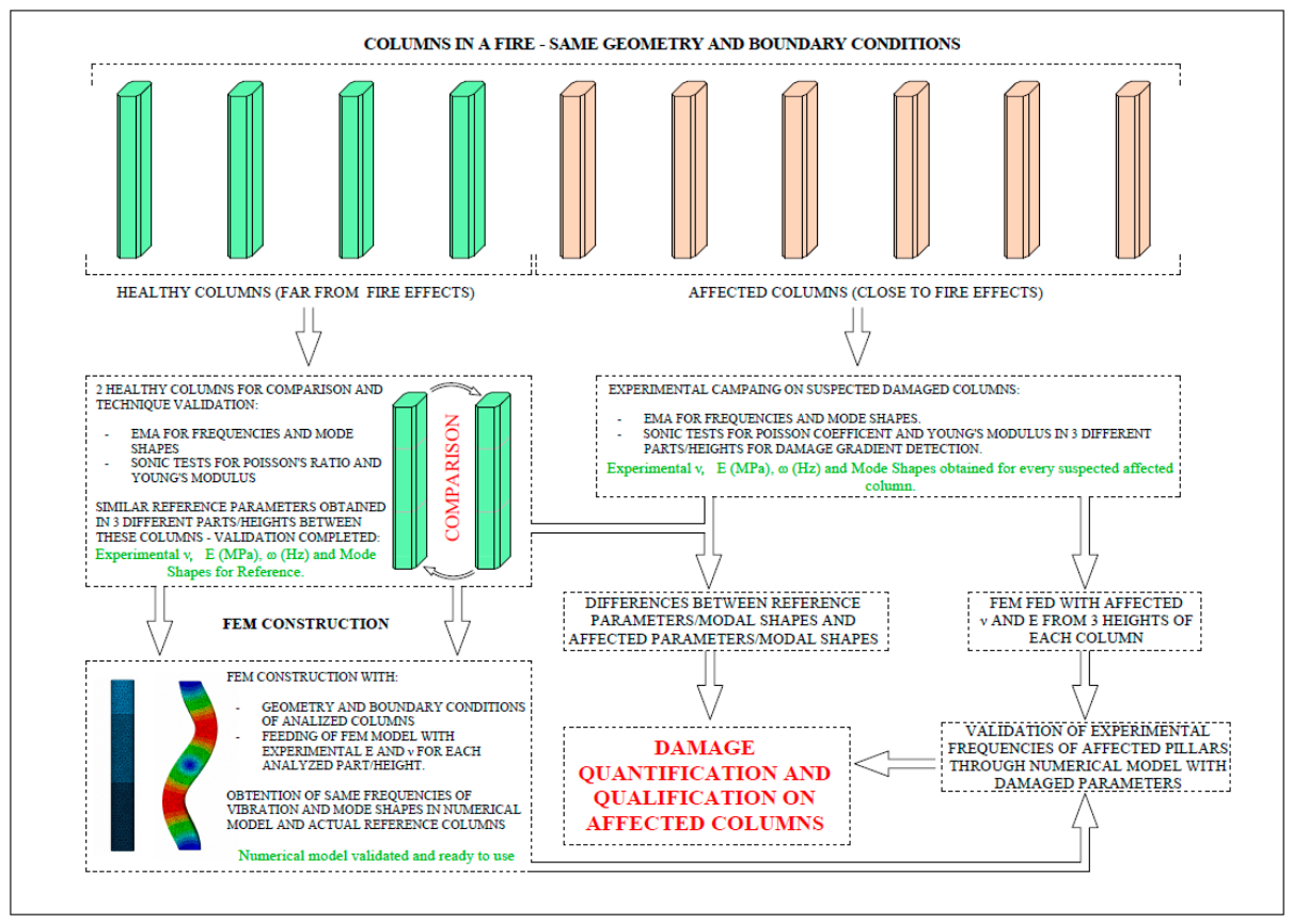
The validation of the proposed non-destructive assessment methodology is carried out through a structured process aimed at verifying its reliability, consistency, and physical coherence. The validation strategy combines experimental cross-comparisons between undamaged columns, numerical–experimental consistency checks on a reference element, and the reproduction of the dynamic response of a fire-damaged column using experimentally derived material properties. The overall validation workflow is summarised in
Figure 4.
3.1. Experimental Cross-Validation on Undamaged Reference Columns
The first validation step focuses on assessing the repeatability and stability of the experimental techniques when applied to structurally equivalent, undamaged columns. For this purpose, two reference reinforced concrete columns were selected. Both elements share identical geometry (H = 2.77 m, 33.5 × 33.5 cm), material characteristics, and boundary conditions, which can be reasonably assumed as fixed–fixed due to the slab–column connections at both ends.
EMA was performed on both reference columns, and the natural frequencies of the first four bending modes in the X direction were identified. The comparison shows that the modal frequencies obtained for the two reference elements are remarkably close. When using reference column 1 (RC1) as baseline, the differences observed in reference column 2 (RC2) remain within a narrow range, with deviations below 3% for all modes. This level of agreement confirms the repeatability of the EMA measurements under in situ conditions and demonstrates that the dynamic response is stable for columns with the same geometry and boundary conditions.
ST was subsequently applied to both reference columns to estimate the dynamic Young’s modulus at three heights along the column (Nodes 2, 7 and 10). The values obtained for the two reference elements show limited dispersion, consistent with the natural variability expected in field measurements due to local heterogeneity of concrete, reinforcement layout, and coupling conditions. Importantly, the observed differences are significantly smaller than those later identified in fire-damaged elements, providing a reliable baseline for distinguishing between healthy and affected behaviour.
The results of this experimental cross-validation are summarised in
Table 1, which reports the EMA frequencies and the dynamic Young’s modulus values obtained from ST for both reference columns. Overall, this first step establishes a robust experimental baseline and confirms that both EMA and ST provide consistent and repeatable results when applied to undamaged columns.
3.2. Numerical Validation on the Reference Column
The second validation step evaluates the consistency between experimentally identified modal parameters and a FE model calibrated using material properties derived from ST. This analysis is performed on Reference Column 1, which serves as a benchmark element with known geometry, boundary conditions, and experimentally measured stiffness distribution.
A three-dimensional FE model of the column was developed, reproducing the geometry and assuming fixed–fixed boundary conditions. In order to incorporate the spatial variability of material properties identified experimentally, the column was divided into three height zones corresponding to the locations of the ST measurements. Each zone was assigned a dynamic Young’s modulus value obtained from ST at Nodes 2, 7 and 10, respectively, while the mass distribution was kept constant.
A numerical modal analysis (NMA) was then performed, and the resulting natural frequencies were compared with those obtained experimentally from EMA. The numerical results show close agreement with the experimental frequencies, with relative differences remaining within a limited range for all four modes considered. These discrepancies are consistent with typical uncertainties associated with in situ modal testing and simplified FE modelling, including assumptions regarding effective end fixity, material homogeneity, and reinforcement idealisation.
The comparison between experimental and numerical results for the reference column is presented in
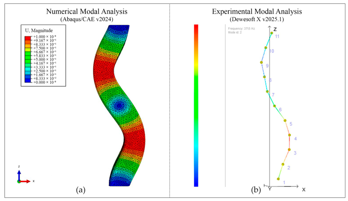
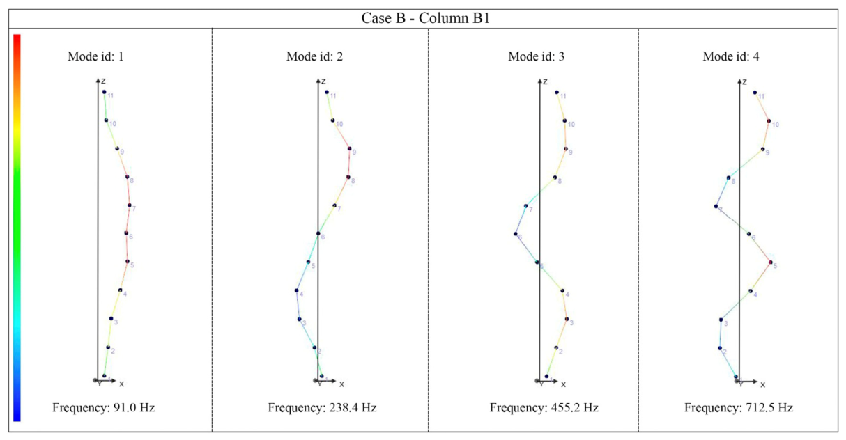
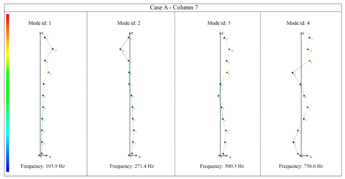
Table 2, which reports EMA frequencies, numerically predicted frequencies, and their relative differences. The agreement observed confirms that the dynamic response identified experimentally can be reproduced by an FE model when the latter is informed by ST-derived elastic properties (
Figure 5). This result provides an important validation of the physical consistency between the two experimental techniques and supports their combined use for post-fire assessment.
3.3. Validation on a Fire-Damaged Column
The final validation step evaluates the capability of the proposed methodology to identify and mechanically reproduce the dynamic behaviour of a fire-damaged reinforced concrete column (FDC) with the same geometry and boundary conditions as the reference column (RC1). This comparison is particularly relevant, as it isolates the effect of material degradation while excluding geometric changes or loss of cross-section.
ST results for the damaged column reveal a substantial reduction in dynamic Young’s modulus when compared to the reference element, as summarised in
Table 3. While the reference column exhibits relatively uniform stiffness values along its height (between approximately 27 and 28 GPa), the damaged column shows markedly lower values, with a pronounced reduction in the upper zone (Node 10), where the dynamic modulus decreases to approximately 8 GPa. This vertical stiffness gradient is physically consistent with a fire exposure scenario in which higher temperatures and longer thermal action affect the upper regions of the column.
EMA results further confirm the presence of severe stiffness degradation. The natural frequencies identified for the fire-damaged column are significantly lower than those of the reference column for all four bending modes considered. The reductions, on the order of approximately 26% for each mode, indicate a substantial loss of global stiffness. Given that the mass and boundary conditions remain unchanged, these frequency shifts can be directly attributed to fire-induced material degradation.
To assess the mechanical consistency of the experimental findings, a FE model with the same geometry and fixed–fixed boundary conditions was calibrated using the dynamic Young’s modulus values obtained from ST. The column was divided into three height zones, each assigned the corresponding modulus measured at Nodes 2, 7 and 10. NMA results obtained from this model reproduce the experimentally identified frequencies of the damaged column with good accuracy, as shown in
Table 3. The relative differences between numerical and experimental frequencies remain within a few percent for all modes, which is considered acceptable given the uncertainties inherent to in situ testing and simplified material modelling.
The agreement between EMA results and NMA predictions demonstrates that the frequency reductions observed experimentally are mechanically consistent with the stiffness degradation quantified by ST. This convergence of independent experimental techniques, supported by numerical reproduction, confirms the robustness of the proposed combined methodology. Importantly, this validation step shows that the method is capable not only of detecting damage, but also of providing a physically coherent quantification of fire-induced stiffness loss in RC columns.
The validation results confirm the internal consistency and reliability of the proposed non-destructive assessment methodology. The experimental cross-validation on undamaged reference columns establishes a stable baseline for healthy structural behaviour, while the numerical–experimental agreement obtained for both the reference and fire-damaged columns demonstrates the mechanical coherence of the combined EMA–ST approach. By reproducing the experimentally observed dynamic response using independently measured elastic properties, the methodology is shown to be physically grounded and suitable for practical application. On this basis, the following section applies the validated methodology to two real post-fire case studies, illustrating its diagnostic capability under different damage scenarios.
5. Discussion
The results obtained from the two real fire case studies allow a detailed evaluation of the proposed EMA–ST methodology under realistic post-fire conditions and provide quantitative evidence of its diagnostic capabilities. Rather than relying on qualitative interpretation alone, the discussion is grounded in the experimental frequency reductions, dynamic Young’s modulus losses, and their spatial distribution observed in the analysed columns. The interpretation follows a comparative framework, given the limited number of tested elements and the in situ nature of the measurements. The robustness of the results is supported by the consistency observed between reference columns, the systematic differences identified between reference and damaged elements, and the agreement between experimental and numerical results.
A first key outcome is the strong quantitative correlation between global dynamic indicators and local stiffness degradation. In Case A, all fire-damaged columns exhibit consistent reductions in the first four bending frequencies identified by EMA, with values ranging from approximately 14% to 27% relative to the reference columns (
Table 4). These reductions are systematically accompanied by significant losses in the mean dynamic Young’s modulus obtained from ST, typically between 35% and 53%. Columns presenting the largest frequency drops (e.g., Columns 4 and 7) also show the most pronounced stiffness losses, confirming that EMA frequency shifts provide a reliable global indicator of damage severity when interpreted together with ST-derived elastic properties. These findings are consistent with previous studies reporting a direct relationship between frequency reduction and stiffness degradation in damaged concrete elements [
24,
25].
In contrast, the results of Case B reveal a markedly different response pattern. Columns in Groups A and C show frequency reductions generally below 7% and corresponding stiffness losses limited to 2–6% relative to their geometry-specific reference columns (
Table 5). These values fall within a narrow band close to the healthy baseline, supporting the conclusion that the structural behaviour of these elements remains largely unchanged. Only Column B1 exhibits clearly differentiated behaviour, with frequency reductions between 14% and 18% and a mean stiffness loss of approximately 15%, placing it between the undamaged and severely damaged regimes identified in Case A. This contrast demonstrates the sensitivity of the methodology across a wide range of degradation levels.
The vertical distribution of stiffness loss identified by ST provides additional insight that cannot be obtained from EMA alone. In Case A, most columns exhibit moderate stiffness reduction at lower measurement nodes and severe degradation toward the upper zones, with dynamic Young’s modulus values locally dropping to 6–10 GPa at Node 10 in several columns. This spatial pattern is consistently reflected in the global frequency reductions and confirms the capacity of the combined EMA–ST approach to link global dynamic response with local material degradation. In Case B, the absence of strong vertical gradients in Groups A and C further supports the classification of these columns as only marginally affected.
The role of numerical modelling as a validation tool is also clarified by the results. For both reference and damaged columns, finite element models calibrated exclusively with ST-derived elastic properties reproduce EMA-identified frequencies with relative differences generally below 10%, even for severely damaged elements. This agreement confirms that the experimentally observed frequency shifts are mechanically consistent with the measured stiffness losses, while also demonstrating that the FE models can remain deliberately simple without compromising their validation role. Importantly, this supports the use of EMA and ST as stand-alone diagnostic tools in practical applications where numerical modelling may not be routinely performed. Similar levels of agreement between experimentally identified modal parameters and FE-based predictions have been reported in previous studies on damaged concrete structures [
24,
26].
From a structural engineering decision-making perspective, the data-driven interpretation of results highlights the practical value of the methodology. In Case A, the combination of frequency reductions exceeding 20% and stiffness losses often above 40% across most columns provides a clear quantitative justification for global strengthening measures. Conversely, in Case B, the methodology prevents over-conservative intervention by identifying a single column requiring attention (B1) while confirming that the remaining elements remain comparable to their reference behaviour. This selective capability directly addresses one of the main challenges in post-fire assessment: balancing safety requirements against economic and operational constraints.
Finally, while experimental uncertainties related to ambient noise, boundary condition idealisation, and local heterogeneity are unavoidable in in situ testing, the comparative framework adopted in this study significantly mitigates their impact. The consistency of trends observed across independent techniques, multiple columns, and two distinct real fire scenarios demonstrates that the proposed EMA–ST methodology yields robust and interpretable results under realistic conditions.
6. Conclusions
This study has presented a non-destructive methodology for the post-fire assessment of RC columns based on the combined use of EMA and ST. By integrating global dynamic indicators with local stiffness estimates, the approach enables a consistent quantification of fire-induced damage under real in situ conditions, with frequency reductions of up to approximately 27% and corresponding stiffness losses reaching 50% in severely affected elements.
The methodology was validated through experimental cross-comparisons on undamaged reference columns and numerical consistency checks using finite element models calibrated with ST-derived elastic properties. Numerical modal analyses reproduced experimentally identified frequencies with relative differences generally below 10%, confirming the mechanical coherence of the proposed indicators.
Application to two real fire scenarios demonstrated the ability of the methodology to distinguish quantitatively between different damage levels. In the severely affected case, consistent reductions in natural frequencies (typically between 14% and 27%) and dynamic Young’s modulus (ranging from approximately 35% to 50%) justified global strengthening measures. In contrast, in the moderate scenario, most columns remained close to their reference behaviour, with frequency reductions generally below 7% and stiffness losses typically below 10%, while only a single element exhibited intermediate degradation, supporting selective intervention strategies.
The combined interpretation of EMA and ST mitigates the limitations of each technique when used independently. EMA provides sensitivity to global stiffness loss, while ST enables localisation and quantification of material degradation along the column height; their integration enhances diagnostic robustness under heterogeneous damage conditions typical of real fires.
Overall, the results demonstrate the practical applicability of the proposed EMA-ST methodology for post-fire assessment of RC columns, supporting objective and cost-efficient structural decision-making in existing buildings. The present study should be understood as a proof of concept based on a limited number of real in situ case studies, and therefore the reported results are not intended to be statistically generalizable. Further studies involving a larger number of tested elements would be beneficial to extend the statistical validation and general applicability of the proposed approach.