1. Introduction
Historic masonry buildings form an essential component of the world’s cultural heritage and reflect the architectural character and engineering practices of earlier civilizations [
1]. Such structures are generally built with solid clay bricks bonded by lime-based mortars and exhibit a complex mechanical behavior, typically featuring high compressive capacity but limited resistance to tensile and shear stresses [
2]. Over long periods of exposure, environmental deterioration, seismic events, and ground movements can significantly reduce the structural integrity of these systems [
3,
4]. According to international conservation guidelines like the Venice Charter, any structural intervention must ensure minimal invasiveness and physicochemical compatibility with the original fabric [
5]. However, the quasi-brittle behavior of traditional masonry often leads to sudden, catastrophic failures under lateral loads, posing a challenge for engineers to develop reinforcement strategies that balance structural safety with heritage preservation principles [
6,
7]. The masonry typology investigated in this study, characterized by low-strength handmade bricks and lime-based mortars, is particularly representative of the historical building stock found in the Mediterranean basin and Southeast Europe, including Turkey. These structures, often dating from the late Ottoman period to the early 20th century, frequently require seismic retrofitting due to the inherent fragility of the original materials. The strengthening interventions proposed here, specifically the use of restoration mortars and polyurea, are designed to address the common structural deficiencies of these regional masonry types—such as poor mortar quality and low unit-to-mortar bond strength—while respecting the aesthetic and material integrity typical of this geographic heritage.
During the last decades, strengthening approaches for masonry structures have progressively evolved from invasive techniques toward the use of advanced composite materials. Fiber-reinforced polymers (FRPs) were initially favored due to their high strength-to-weight ratios; however, the use of organic resins often resulted in poor vapor permeability and thermal incompatibility with historic substrates [
8,
9]. Therefore, Textile Reinforced Mortar (TRM) systems have gained considerable attention and widespread use in masonry strengthening applications, which utilize inorganic restoration mortars as a matrix for high-strength fiber grids [
10,
11]. Recent research emphasizes that the mechanical efficiency of TRM is heavily dependent on the bond characteristics between the textile and the mortar [
12,
13]. Portal et al. [
14] and Yin et al. [
15] have shown that textile surface treatments and mortar thickness significantly influence the energy dissipation capacity. Specifically, using restoration mortars that mimic the modulus of elasticity of historic brickwork is critical to prevent premature debonding and ensure a uniform stress distribution across the masonry surface [
16,
17].
Despite the proven performance of Carbon-TRM (C-TRM), researchers have recently explored even more ductile and rapidly applicable solutions to address the limitations of rigid composites. In this context, sprayed polyurea has emerged as a high-performance elastomeric strengthening material. Polyurea is a synthetic elastomeric polymer distinguished by its high tensile strength and exceptionally large elongation capacity, often exceeding 300% [
18,
19]. While its primary applications were initially limited to blast mitigation and waterproofing [
20], its role in structural retrofitting is a rapidly expanding field. García-Ramírez et al. [
21] and Chen and Ma [
22] have demonstrated that polyurea coatings create a continuous, highly adhesive “membrane” that confines masonry units during failure. Unlike traditional reinforcements studied by Franzoni and Gentilini [
23] and Borri et al. [
24], this hyper-elastic layer prevents the brittle spalling of bricks and transforms the failure mechanism into a highly ductile and energy-dissipating mode [
25,
26].
A review of the current literature indicates a clear research gap regarding the combined use of restoration mortars—serving as both jointing and base substrates—integrated with either C-TRM or sprayed polyurea on historic solid clay brick masonry. Most existing literature focuses on modern cementitious mortars or examines these strengthening materials in isolation [
27,
28]. There is a scarcity of comparative experimental data that evaluates how these innovative systems perform under standardized diagonal tension and shear loads (ASTM E519) when applied to identical historic substrates [
29]. Recent studies have emphasized that understanding the mechanical hierarchy between masonry units and mortar layers is crucial for accurate capacity assessment. Particularly, in cases where the masonry units exhibit lower strength compared to the mortar—a common scenario in historic structures—the global behavior is governed by the interaction at the interface [
30]. Additionally, the non-linear behavior of such ‘weak unit–strong mortar’ combinations under compression and shear reveals significant insights into the failure mechanisms and stress distribution within the wall assembly [
31]. Furthermore, the comparative performance of high-stiffness carbon textiles versus the hyper-elastic nature of polyurea, specifically when integrated with restoration mortars, requires further scientific clarification to provide reliable design guidelines for heritage conservation tailored to different structural requirements.
The engineering motivation behind integrating restoration-grade mortars with advanced polymers like polyurea lies in the inherent conflict between heritage conservation and structural safety. While lime-based restoration mortars are essential for physicochemical compatibility and vapor permeability, their low tensile and shear bond strengths often limit the overall structural recovery of the masonry assembly. Traditional strengthening methods (e.g., stiff cementitious TRM) can create a “rigidity mismatch” that leads to localized stress concentrations and brittle failure of the fragile historic bricks. Therefore, the strategic integration of a low-modulus mortar (for substrate compatibility) with a high-elongation elastomeric membrane (for confinement and energy dissipation) aims to create a functionally graded strengthening system. This synergy is intended to allow the masonry to undergo significant deformation without collapse, effectively decoupling the aesthetic/material requirements of restoration from the mechanical demands of seismic retrofitting.
The engineering necessity of combining restoration-grade mortars with advanced strengthening systems (C-TRM and Polyurea) arises from the technical requirement to treat the masonry surface before applying high-performance reinforcements. In historic preservation, applying a polymer or a textile grid directly onto a degraded or irregular brick surface can lead to localized stress concentrations and poor interfacial bonding. The restoration mortar acts as a ‘buffer layer’ that regularizes the substrate, ensures chemical compatibility, and maintains the vapor permeability of the wall assembly. From a structural standpoint, this combination creates a composite system where the mortar facilitates a uniform stress transfer from masonry to the reinforcement. Without this dual-layer approach, the full tensile capacity of C-TRM or the confining effect of polyurea could not be effectively mobilized, potentially leading to premature debonding or damage to the fragile historic units. Therefore, evaluating these materials as a combined system is not merely a comparative exercise but a fundamental requirement for a durable and compatible retrofitting design.
Unlike existing comparative studies that focus on high-strength industrial mortars or non-reversible FRP systems, this research addresses a critical gap in the preservation of heritage structures: the balance between high structural enhancement and physicochemical compatibility. The core scientific question of this study is whether a highly elastic, sprayable organic membrane (Polyurea) can outperform traditional carbon-textile systems when applied over low-modulus, lime-based restoration mortars specifically designed for fragile, handmade historic bricks. While literature exists on polyurea or TRM separately, the synergistic evaluation of these three distinct levels of intervention—ranging from traditional restoration mortar to advanced elastomeric confinement—within a strictly conservation-aligned framework (prioritizing reversibility and substrate integrity) constitutes the primary novelty of this work.
To address the research gap, the present research implements a comprehensive experimental program focused on the structural enhancement of historic masonry heritage. The primary objective is to evaluate and compare the effectiveness of three distinct strengthening strategies applied symmetrically to both faces of the specimens: (i) restoration mortar, (ii) carbon textile-reinforced mortar (TRM), and (iii) an innovative sprayed polyurea system. The novelty of this research lies in its multi-method comparative approach, the use of historic-representative clay bricks, and the detailed analysis of the interaction between these advanced materials and the masonry substrate.
The experimental methodology was organized into two complementary stages. The first stage involved fundamental material characterization through flexural and compressive strength tests on the historic clay bricks and the restoration mortar to establish a baseline for the mechanical properties. In the second stage, structural testing was conducted on a total of forty masonry specimens, divided into four distinct groups: an unreinforced control group and three strengthened groups consisting of restoration mortar only, restoration mortar with carbon textile reinforcement, and restoration mortar with sprayed polyurea. The primary focus of this research is the evaluation of double-sided strengthening strategies, all of which were applied symmetrically to both faces of the specimens. In this context, restoration mortar served a dual purpose: as the original jointing material for the masonry construction and as a uniform strengthening layer for the reinforced groups. Specifically, twenty triplet specimens were subjected to shear strength tests to determine the maximum shear force and shear strength in accordance with EN 1052-3 [
32], while twenty-four-unit masonry wallets underwent diagonal compression tests following ASTM E519 [
29] to evaluate critical parameters including failure load, maximum shear stress, vertical strain capacity, and failure modes. Furthermore, tensile adhesion (pull-off) tests were performed on the sprayed polyurea to evaluate its bond performance and interface mechanism with the historic clay brick substrate in accordance with ASTM D4541 [
33].
The experimental findings demonstrate that while all investigated double-sided strengthening methods significantly improved the structural capacity, the polyurea-strengthened specimens exhibited the most remarkable performance. This research highlights the unique advantages of polyurea, including its exceptional hyper-elastic flexibility, rapid ease of application, and non-invasive profile. By providing a direct comparison of failure loads, shear stress distributions, and deformation capacities, this study offers critical, evidence-based guidance for the selection of high-performance strengthening solutions for the preservation of global architectural heritage.
2. Materials and Methods
The experimental framework of this research was designed to provide a systematic and comparative evaluation of innovative strengthening techniques applied to masonry specimens. To ensure a robust scientific basis, the methodology followed a two-phase integrated approach: (i) fundamental material characterization to establish the mechanical properties of the base components, and (ii) structural testing on masonry specimens to quantify the efficiency of the reinforcement systems. The first phase focused on determining the flexural and compressive strengths of the handmade clay bricks and the restoration mortar, which served as the essential mechanical baseline for all subsequent analyses.
The second phase involved the production and structural assessment of forty masonry specimens, meticulously divided into four experimental groups to compare unreinforced control samples with three distinct retrofitting strategies: unreinforced control specimens (G), strengthening with restoration mortar only (RTH), strengthening with restoration mortar combined with carbon textile reinforcement (RTHT) and strengthening with restoration mortar followed by an innovative sprayed polyurea system (RTHP).
A key feature of this study is the dual application of the restoration mortar, which was utilized both as the original jointing material during construction and as a consistent 8 mm strengthening layer for all reinforced groups (RTH, RTHT, RTHP). All strengthening configurations were applied symmetrically to both faces of the specimens to evaluate their effectiveness under critical loading conditions.
Structural performance was rigorously evaluated through standardized testing protocols. Specifically, twenty triplet specimens were subjected to shear tests to determine the maximum shear force and strength parameters in accordance with EN 1052-3 [
32]. To evaluate the diagonal tension behavior, twenty-four-unit masonry wallets underwent uniaxial diagonal compression tests following ASTM E519 [
29], providing critical data on failure loads, maximum shear stresses, and deformation capacities. Furthermore, the bond performance and interface mechanism between the sprayed polyurea and the historic clay brick substrate were characterized through tensile adhesion (pull-off) tests conducted in accordance with ASTM D4541 [
33].
2.1. Material Characterization
The reliability of structural retrofitting interventions on masonry heritage is fundamentally dependent on the mechanical compatibility between the original substrate and the newly applied strengthening materials [
4,
16,
34]. Consequently, a comprehensive material characterization was conducted to establish a robust mechanical baseline for the constituent components utilized throughout the experimental program [
12,
35]. This characterization phase is essential not only for evaluating the synergistic efficiency of the proposed hybrid strengthening systems but also for ensuring that the experimental findings are representative of actual historic masonry behavior [
1,
23,
36]. By quantifying the compressive and flexural properties of the bricks and the specialized restoration mortar, this stage provides the necessary parameters for interpreting the failure mechanisms and load-transfer characteristics observed during the structural testing of the masonry specimens [
17,
28].
2.1.1. Historic-Representative Clay Bricks
The masonry units utilized in this study are designated as HT (handmade clay bricks), which are solid units produced through traditional kiln-firing processes to replicate heritage masonry characteristics. According to the definitions in EN 771-1 [
37], these units represent ceramic-bonded masonry materials obtained by firing clay and loamy earth at high temperatures.
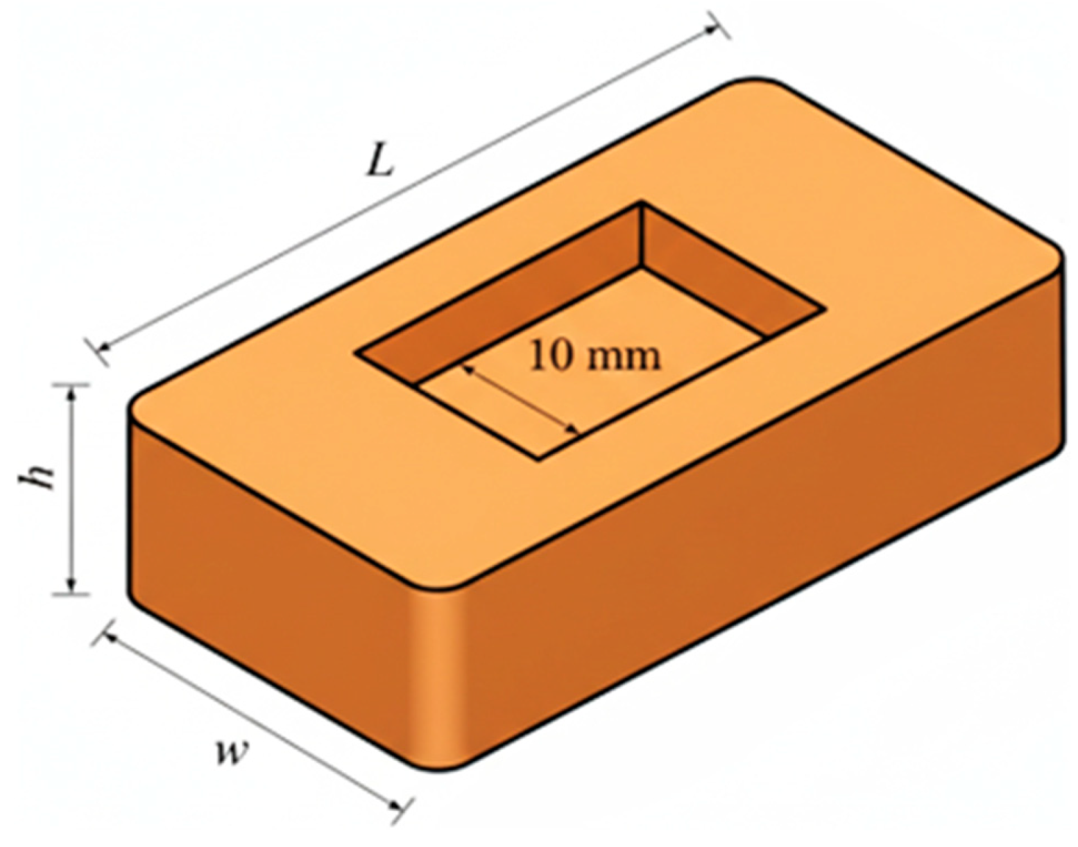
Figure 1 displays the overall geometry of the HT units, illustrating the characteristic “frog” or mortar pocket located on the bed surface. As specified in the literature [
38], this mortar pocket is designed with a depth not exceeding 10 mm and a maximum edge distance of 20 mm, consistent with EN 12390-5 [
39] requirements. The dimensional properties, weight measurements, and statistical variations for the tested specimens (HT1–HT5) are detailed in
Table 1.
The mechanical characterization was conducted through flexural and compressive strength tests following ASTM C67-11 [
40] protocols.
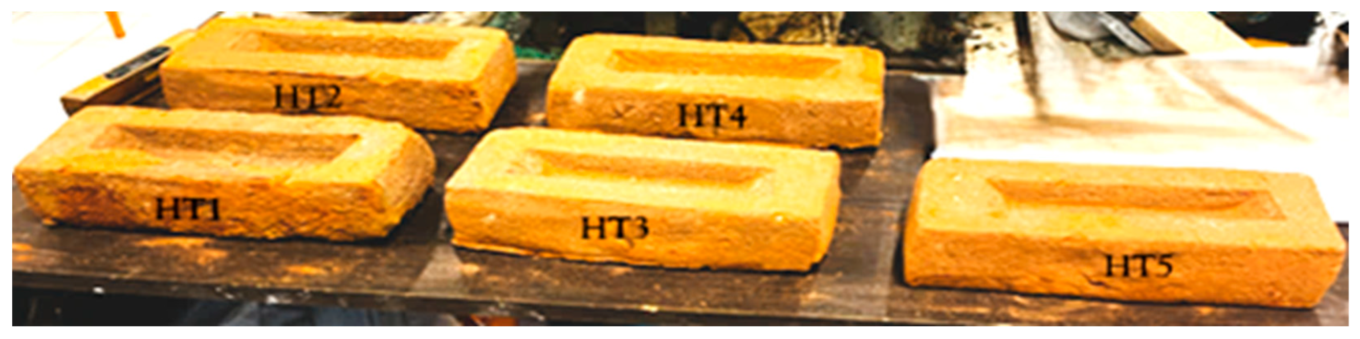
Figure 2 shows the five solid clay brick specimens prepared for the tests. To ensure uniform and linear stress distribution, gypsum capping was applied to the loading surfaces of all specimens.
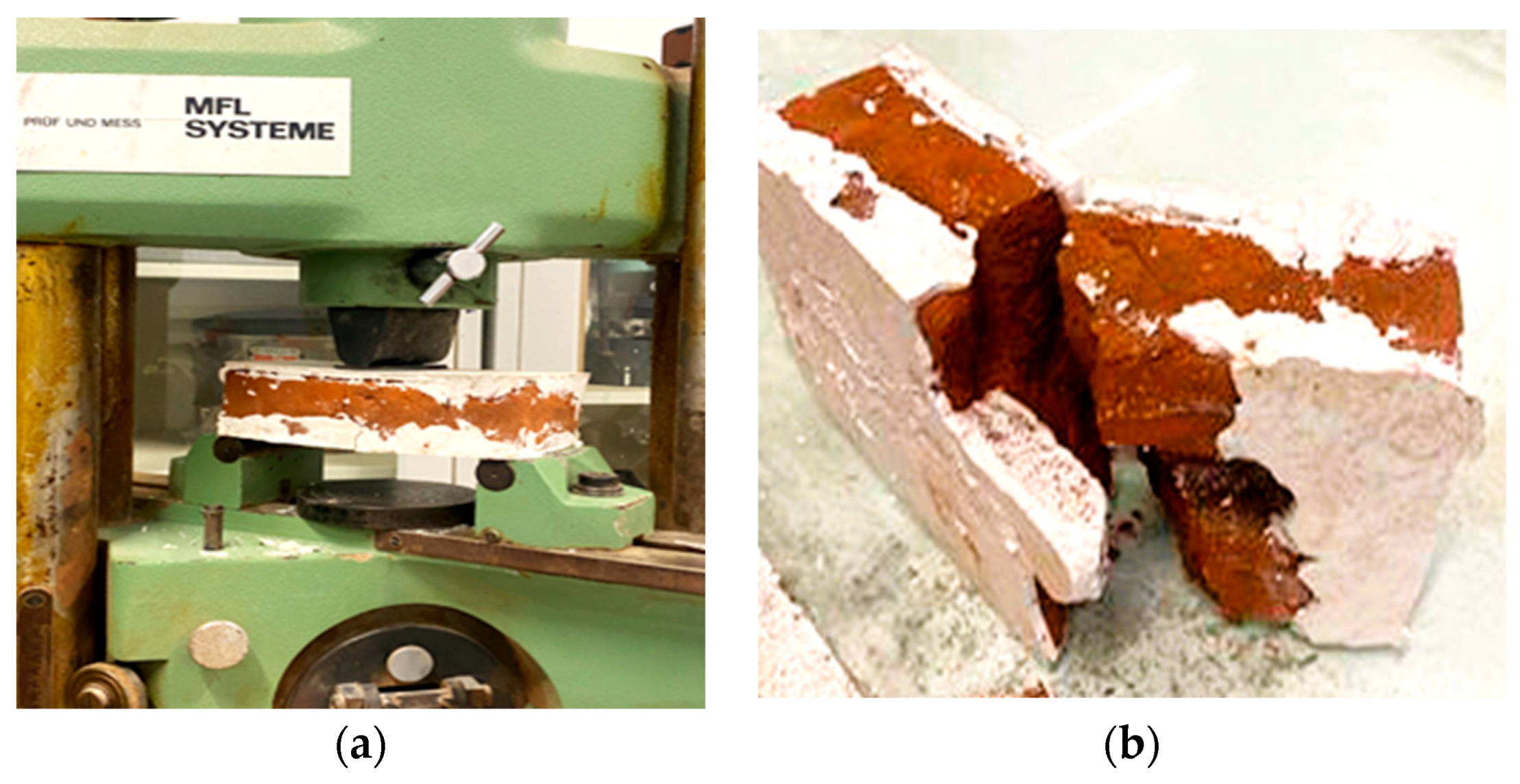
The experimental setup for the flexural strength (
) evaluation, utilizing an MFL SYSTEME universal testing machine (MFL Prüfsysteme GmbH, Ratingen, Germany) with a 300 kN capacity and a 200 mm support span (
), is depicted in
Figure 3a. The flexural strength was calculated using Equation (1) according to the standard [
38]:
where
is the maximum load (N),
is the specimen width (mm), and
is the height (mm). The results indicated a mean flexural strength of 1.72 MPa, as detailed in
Table 2. Typical mid-span brittle failure modes observed in the brick units after the flexural test are illustrated in
Figure 3b.
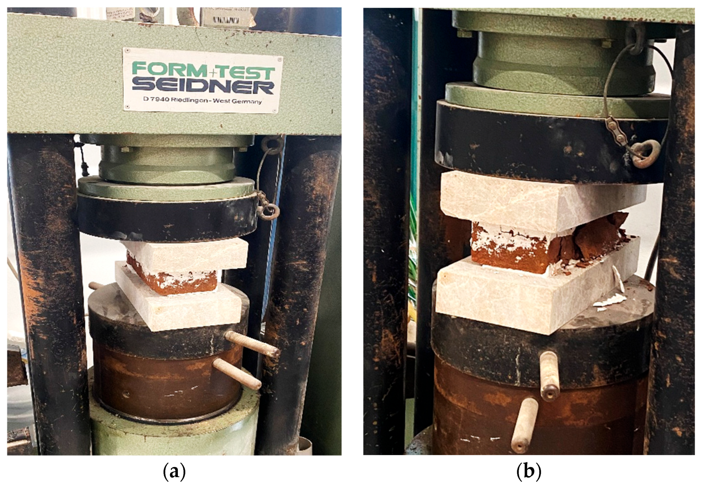
The compressive strength
was assessed using a Seidner Form Test device (Seidner GmbH, Riedlingen, Germany), and the testing procedure is illustrated in
Figure 4. The compressive strength was calculated according to Equation (2) following ASTM C67-11 [
40]:
where
represents the maximum compressive load at failure (N) and
denotes the cross-sectional area of the loading plates (mm
2). The HT series reached a mean compressive strength of 6.76 MPa, which is summarized alongside the flexural results in
Table 2.
To assess data dispersion, the individual deviations and group statistical parameters—namely Standard Deviation (SD) and Coefficient of Variation (CoV)—were determined for the specimens in
Table 2. The resulting CoV values (22.3–28.5%) are consistent with the inherent heterogeneity typically observed in handmade masonry units and historic materials [
30,
34,
38]. These values confirm that the experimental results are statistically representative of non-industrial clay bricks and provide a reliable baseline for the subsequent structural analysis.
2.1.2. Restoration Mortar
In this study, a ready-to-use restoration mortar (RTH) was utilized. To ensure terminological clarity, this single material is referred to as “restoration mortar” throughout the study, serving a dual purpose: (i) as the jointing mortar for the construction of masonry specimens and (ii) as the strengthening matrix for the reinforced groups. RTH is a high-strength, cement-free material specifically designed for historic structures, formulated with natural hydraulic lime (NHL) and reinforced with basalt fibers (Fiber MF).
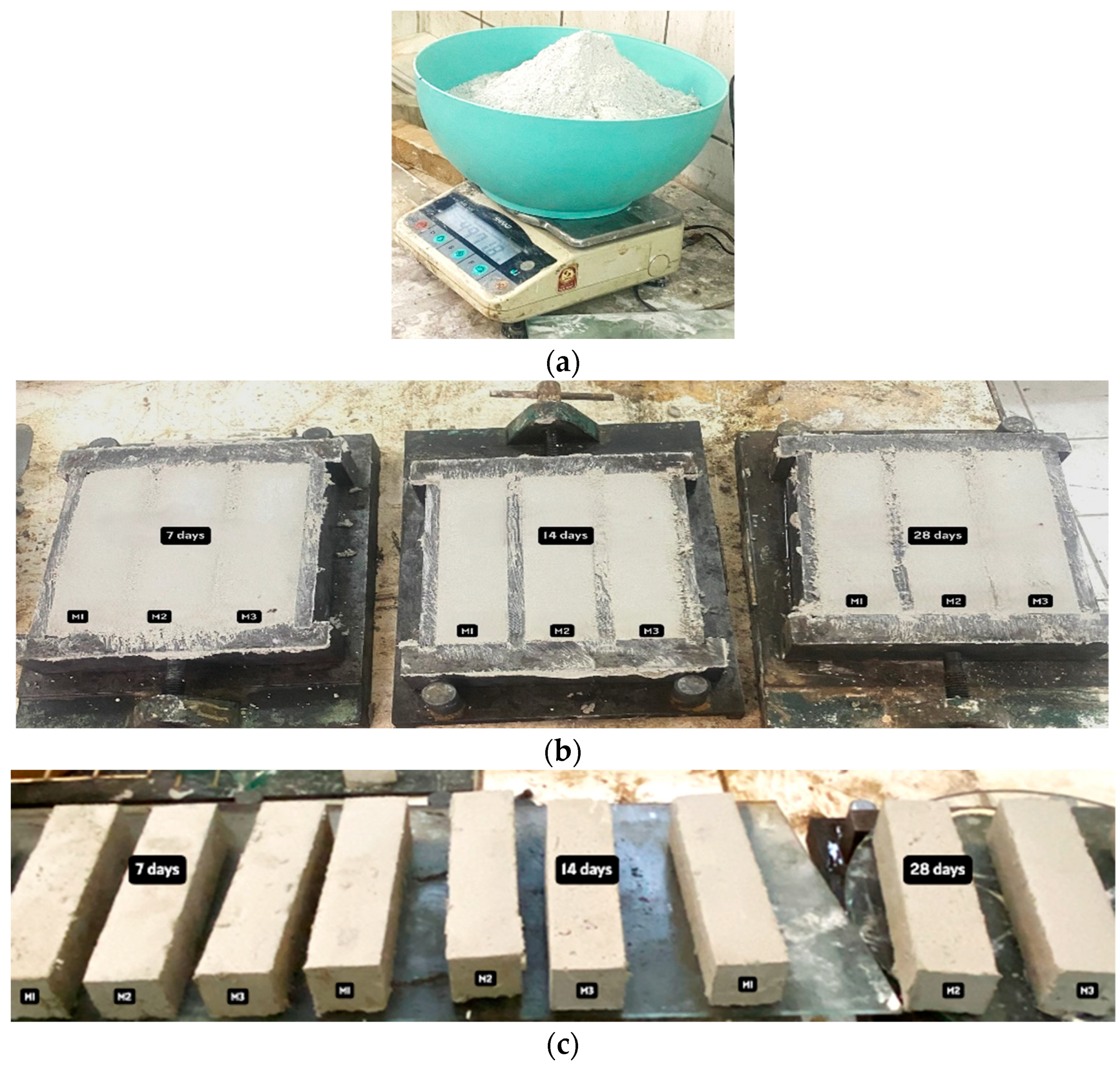
Restoration mortar was prepared following the manufacturer’s technical instructions with a water-to-mortar ratio of 0.28. The preparation involved pouring the required amount of water into a mixing container, followed by the gradual addition of the dry mortar. To achieve a homogeneous consistency, the mixture was stirred using a low-speed mechanical stirrer for approximately 4 min. In accordance with EN 1015-11 [
41], prism specimens with dimensions of 40 × 40 × 160 mm were cast in lubricated molds at the affiliated university laboratory. Faculty of Architecture, Building Materials Laboratory. A total of nine specimens were cast; after 1 h in the molds, they were demolded and subjected to mechanical testing after curing periods of 7, 14, and 28 days. The preparation stages of the restoration mortar specimens are illustrated in
Figure 5.
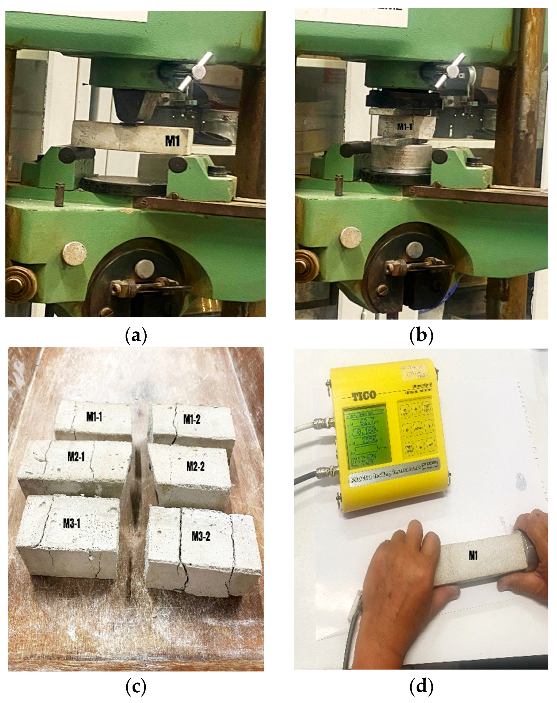
The flexural and compressive strengths were determined using an MFL SYSTEM testing machine (MFL Prüfsysteme GmbH, Ratingen, Germany) in accordance with EN 1015-11 [
41]. Three-point bending tests were performed with a span of 150 mm between supports, applying a constant loading rate between 10 N/s and 50 N/s. Subsequently, compressive strength tests were conducted on the broken prism halves, as specified in the standard, with a loading rate ranging from 50 N/s to 500 N/s [
41]. The results of these tests are summarized in
Table 3.
Additionally, Ultrasonic Pulse Velocity (UPV) measurements were performed on 28-day specimens using a PROCEQ TICO device (Proceq SA, Schwerzenbach, Switzerland). The average UPV was measured at 3150 m/s. The application of the flexural and compressive strength test on the mortar specimens and UPV testing procedure on 40 × 40 × 160 mm specimens are depicted in
Figure 6.
To evaluate the bonding performance between the mortar and the brick units, pull-off tests were conducted according to EN 12004-2 [
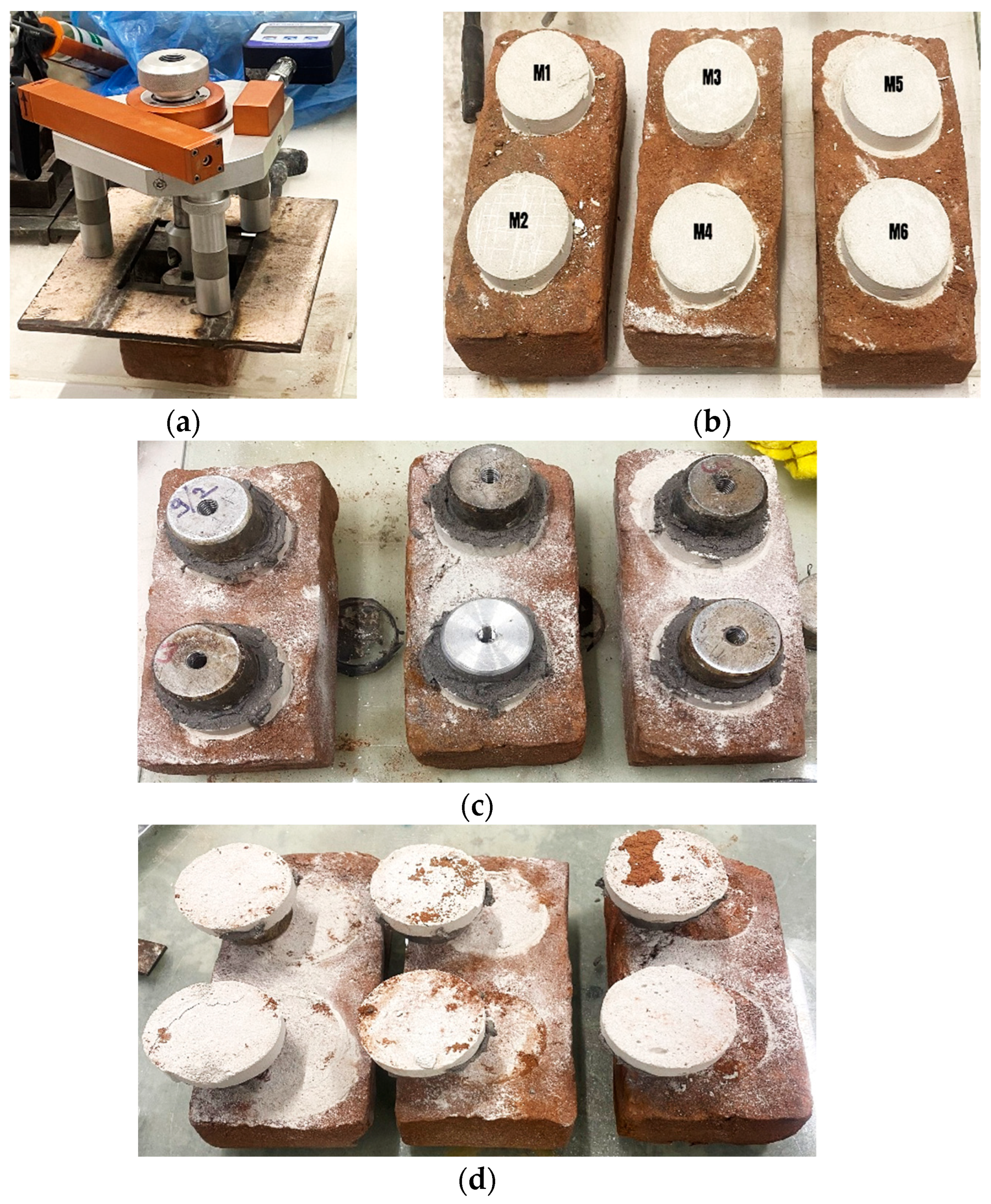
42]. After 28 days of laboratory curing, the specimens were tested using a Pull-Off device (Proceq SA, Schwerzenbach, Switzerland). Six cylindrical mortar specimens (70 mm diameter and 15 mm height) and the typical failure modes are shown in
Figure 7.
The bond strength results and the peak loads recorded during the tests are summarized in
Table 4. The average bond strength was determined to be 0.036 MPa. The typical failure mode was observed as the mortar tearing fragments from the brick surface, indicating a robust mechanical interlock between the materials.
2.1.3. Strengthening Components
In this study, two distinct types of advanced materials were employed for the lateral strengthening of masonry specimens: carbon textile reinforcement and a spray-applied polyurea system. To ensure proper load transfer and composite action, both strengthening solutions were applied directly onto the surface of the restoration mortar (RTH).
The primary reinforcement utilized was a high-performance carbon fiber textile mesh. Carbon fibers were selected for their exceptional mechanical properties, typically exhibiting a tensile strength ranging from 3800 to 4800 MPa and a high modulus of elasticity between 230 and 240 GPa [
43]. The reinforcement featured a bidirectional grid geometry with a clear mesh opening of 25 × 25 mm, designed to ensure adequate penetration and mechanical interlocking of the restoration mortar through the grid apertures. This grid-like reinforcement, with a characteristic elongation at break of approximately 1.5–1.8%, was embedded within the RTH layers to provide significant structural ductility and load-carrying capacity, following the established criteria for fabric-reinforced systems [
44].
In addition to the textile-based reinforcement, a two-component, 100% solid spray polyurea system was used as an alternative strengthening layer. This solvent-free elastomeric membrane was applied using high-pressure spray equipment directly over the prepared RTH surface to form a composite strengthening phase. In contrast to the rigid behavior of carbon textiles, the polyurea system functions as a highly ductile, seamless elastomeric membrane. According to established literature, such systems typically provide a tensile strength of 15 to 25 MPa and a modulus of elasticity between 30 and 100 MPa [
45]. The most prominent feature of the polyurea system is its exceptional energy dissipation capacity, facilitated by an elongation at break ranging from 300% to 500%, evaluated based on standardized tensile testing methods for elastomers [
46].
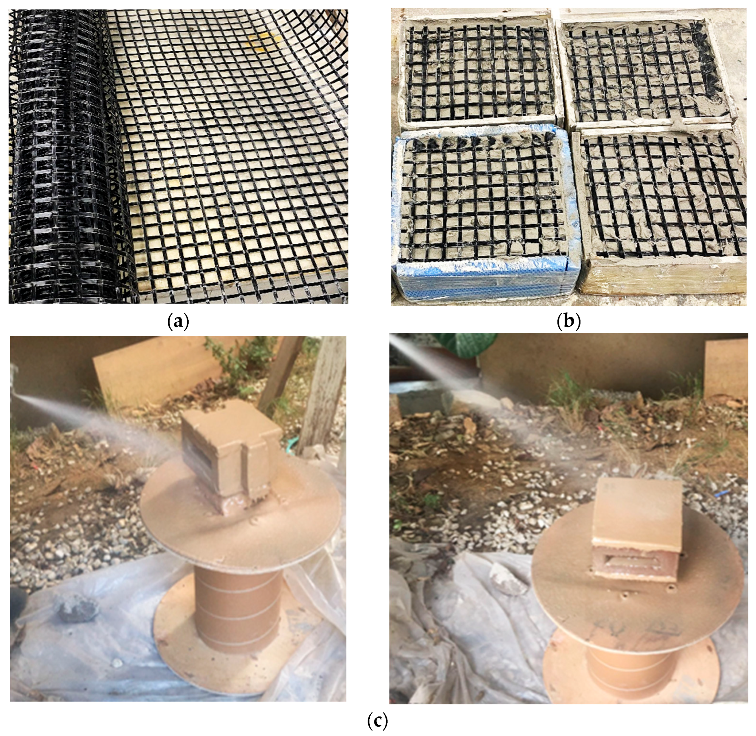
The application process for both systems is depicted in
Figure 8. The carbon textile was applied by embedding the mesh into the first layer of RTH, followed by a second cover layer. For the polyurea application, the masonry surface was cleaned and primed to ensure a high-strength bond between the elastomeric membrane and the brick units.
2.2. Brick Wall Specimen Preparation and Strengthening Configurations
2.2.1. Construction and Initial Curing
The experimental program involved the construction of 40 historical masonry wall specimens using solid clay bricks and restoration mortar. To determine the mechanical characteristics, 20 specimens were prepared as triplets for shear strength testing, and 20 specimens were prepared as quadruplets for diagonal compression testing. The number of specimens was selected to ensure statistical reliability and consistency with commonly adopted experimental programs in masonry testing. The masonry wall specimens were constructed with specific dimensions to ensure full compatibility with the loading capacities and boundary conditions of the laboratory testing equipment. Specifically, two types of geometries were produced: Triplet specimens, intended for shear strength testing, were constructed with dimensions of approximately 220 × 180 × 100 mm (length × height × width), consisting of three brick units and two mortar joints. Four-unit masonry wallets, designed for uniaxial diagonal compression testing, featured dimensions of approximately 220 × 245 × 100 mm (length × height × width), incorporating four brick units to achieve the required aspect ratio for diagonal loading.
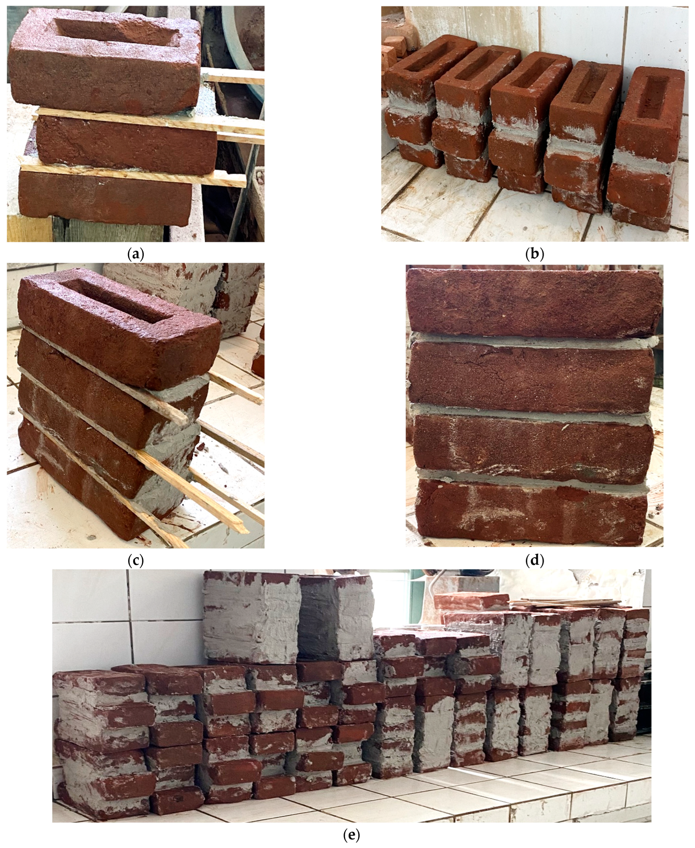
Prior to construction, the solid bricks were saturated with water to prevent the absorption of the mixing water from the mortar, thereby ensuring enhanced bond strength and overall durability. All specimens were built with a uniform mortar joint thickness of 8 mm. During the assembly process, wooden molds were utilized to support the walls and ensure proper alignment and perpendicularity, as shown in
Figure 9.
Following the construction phase, the 40 masonry specimens underwent an initial curing period of at least 28 days under controlled laboratory conditions. To comply with standard testing protocols, the environment was maintained at a constant temperature of 20 ± 2 °C and a relative humidity of 65 ± 5% [
41]. This period allowed for the full hydration of the restoration mortar and the stabilization of the masonry units before the strengthening phase or mechanical testing.
2.2.2. Strengthening Strategies, Application, and Secondary Curing
In this study, 30 out of the 40 produced masonry specimens were strengthened using various techniques to evaluate their structural contribution. The specimens were categorized into four distinct experimental groups based on the reinforcement strategy applied: unreinforced control specimens (G), specimens strengthened with restoration mortar (RTH), specimens reinforced with a combination of restoration mortar and carbon textile mesh (RTHT), and specimens strengthened with restoration mortar followed by a spray polyurea coating (RTHP). The detailed experimental test matrix, including the strengthening configurations, is summarized in
Table 5.
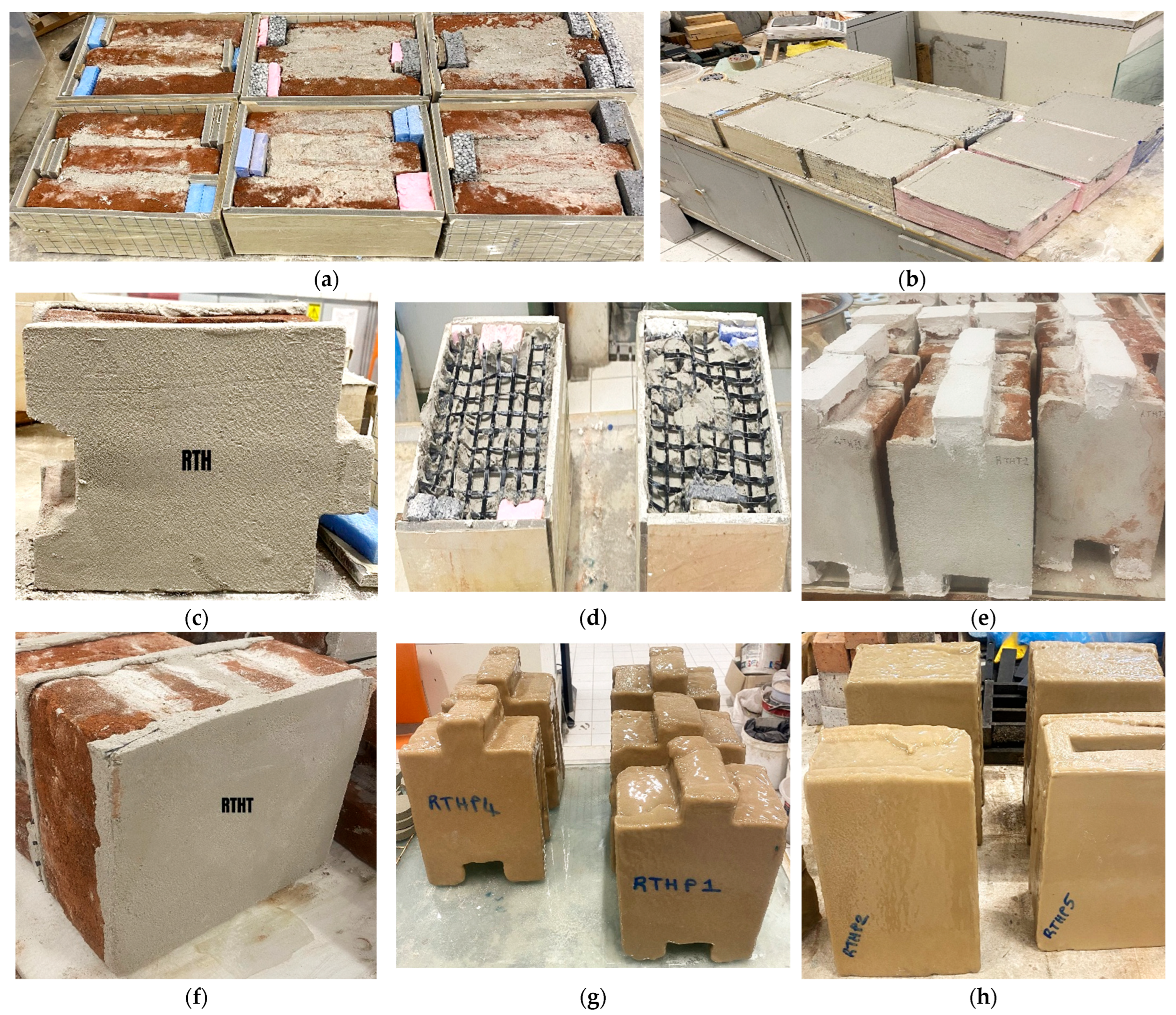
All strengthening layers were applied symmetrically to both faces of the specimens to ensure structural balance and prevent eccentric loading effects during testing. For the RTH group, an 8 mm thick layer of restoration mortar was applied. The carbon textile reinforcement used in this study consists of bidirectional carbon fibers with a tensile strength of approximately 5000 MPa and mesh spacing of 25 mm. In the RTHT group, 25 × 25 mm grid carbon textile was embedded between two layers of RTH, maintaining a total thickness of 8 mm. For the RTHP group, after the initial 8 mm RTH layer reached sufficient stability, an average thickness of 8 mm spray polyurea coating was applied, resulting in a composite hybrid system. The thickness of the sprayed polyurea coating in the RTHP group was specifically set at 8 mm to ensure a direct geometric and volumetric comparison with the restoration mortar thickness used in the RTH and RTHT groups. This decision was based on the necessity for comparability between different strengthening systems rather than a specific standard, as there is currently no unified international standard for polyurea thickness in structural masonry strengthening. Furthermore, an 8 mm thickness was considered a practical upper limit for such applications to provide a continuous, high-performance elastomeric containment without significantly altering the architectural dimensions of the historic units. The systematic application procedures for the reinforcement of masonry specimens are presented in
Figure 10.
Following the application, all reinforced groups (RTH, RTHT, and RTHP) underwent a secondary 28-day-curing period under the same controlled laboratory conditions (20 ± 2 °C and 65 ± 5% relative humidity) to ensure the composite systems achieved their full design strength [
41]. Notably, RTHP specimens were transported to a specialized facility for the high-pressure spray application. Due to the rapid-curing nature of the polyurea, these specimens reached their mechanical maturity shortly after the application, allowing for a synchronized testing schedule across all groups. The physicochemical compatibility of sprayed polyurea with the historic brick substrate was evaluated based on thermal and hygroscopic performance metrics. Regarding thermal expansion, polyurea exhibits a coefficient (α) significantly higher than that of historic clay bricks. However, its exceptionally low elastic modulus allows the coating to act as a flexible “stress-buffer,” absorbing the differential thermal strains without inducing interlaminar stresses that could lead to substrate spalling [
47]. Furthermore, in terms of vapor permeability, while polyurea is inherently a water-resistant membrane, research indicates that at the applied thickness (8 mm), it maintains a degree of breathability that allows for the migration of moisture from the masonry core to the exterior [
48]. This prevents the entrapment of moisture within the brick units, thereby mitigating the risk of salt crystallization and freeze–thaw damage, ensuring long-term physical compatibility with the heritage fabric.
Regarding the interfacial behavior between the carbon textile and the RTH mortar, the composite action is primarily governed by mechanical interlocking rather than pure chemical adhesion. The 25 × 25 mm grid spacing of the carbon textile allows for the formation of robust mortar bridges across the reinforcement layer. This configuration ensures that the textile is physically anchored within the 8 mm thick RTH matrix. Observational data from the diagonal compression tests support this; no interlaminar debonding or textile slippage was detected during the progressive loading stages. Instead, the cracks crossed the reinforcement grid without causing separation, confirming that the shear transfer at the textile-mortar interface was sufficient to mobilize the full tensile capacity of the carbon fibers. This confirms reliable composite action, even in the absence of specialized pull-out testing or DIC displacement mapping.
2.3. Experimental Setup and Testing Procedures
2.3.1. Shear Tests on Triplet Masonry Wallets
Shear failure is recognized as the primary failure mode for masonry structures subjected to horizontal loads, such as seismic actions and wind pressure [
49,
50]. To evaluate the bond strength and shear behavior of the bed joints, triplet shear tests were conducted in accordance with the TS EN 1052-3 standard [
32]. This experimental protocol also allows for the investigation of the influence of joint thickness on the overall shear capacity.
A total of five specimens were evaluated for each experimental group (G, RTH, RTHT, and RTHP) at Building Materials Laboratory of the affiliated university. To ensure uniform stress distribution and achieve accurate results, gypsum capping was applied to the contact surfaces of the specimens. The tests were performed using a calibrated Schindler Form Test machine with a maximum capacity of 300 kN and a maximum specimen height limit of 400 mm. The flexible loading head of the device ensured an even distribution of the applied load during the experiments.
The shear strength (
) for each masonry specimen was calculated based on the maximum shear force recorded at the failure point, as presented in Equation (3), following the calculation procedure defined in TS EN 1052-3 [
32]:
where
is the shear strength (MPa),
is the maximum shear force (N), and
is the cross-sectional area parallel to the bed joints (mm
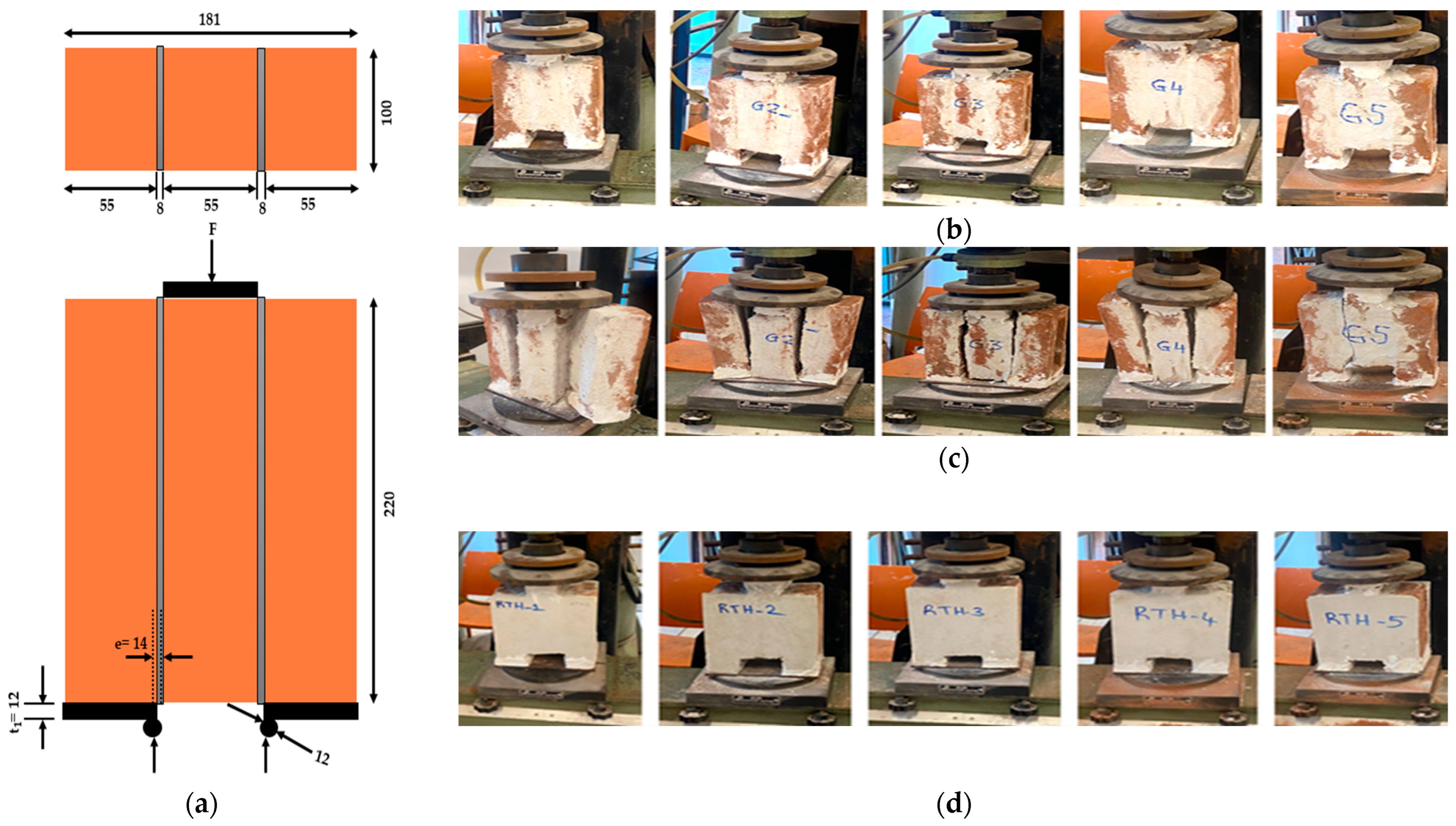
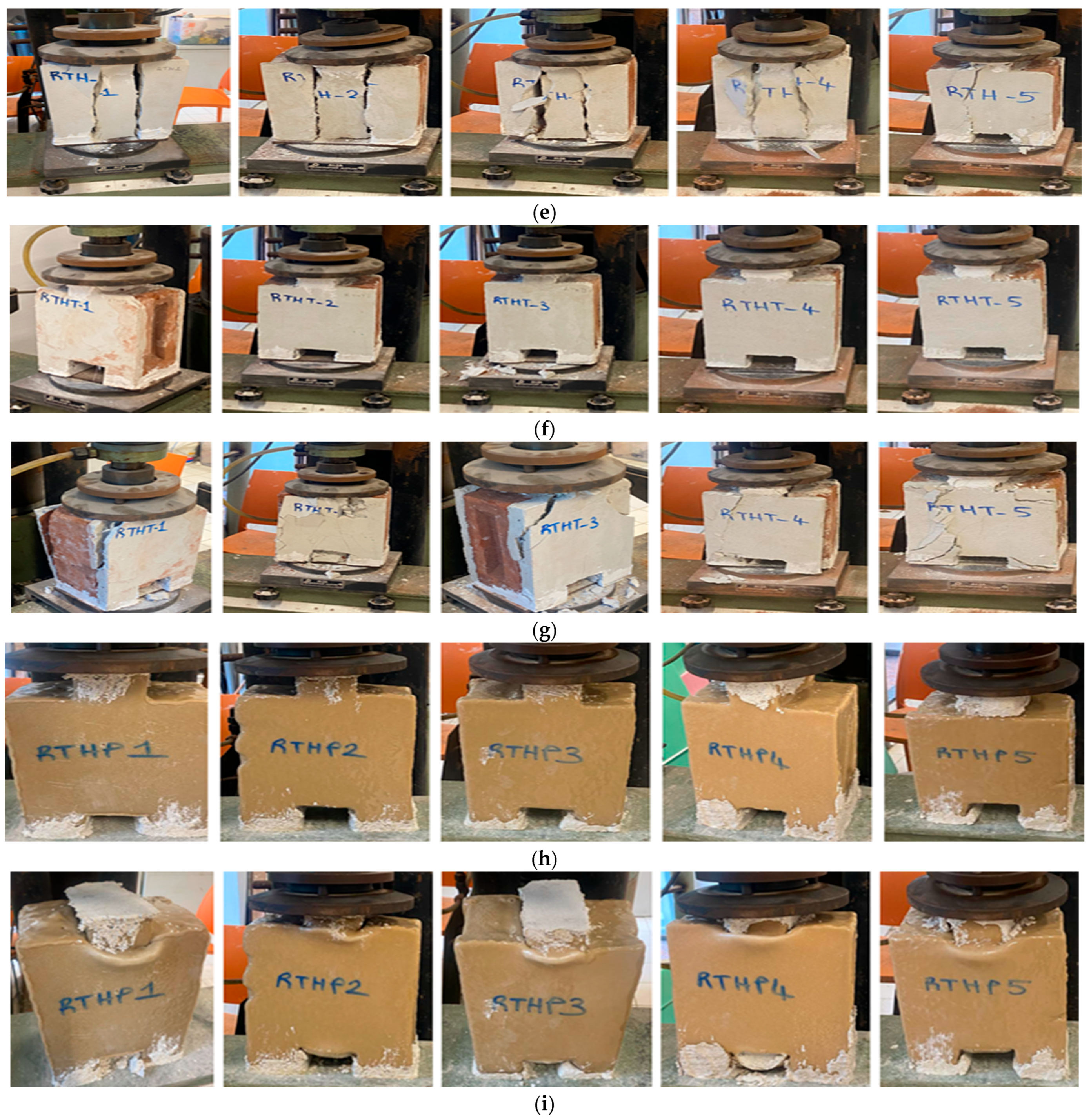
2). The experimental test setup and the detailed loading configuration for all triplet specimens are illustrated in
Figure 11.
The unreinforced control group (G) exhibited a mean shear strength of 0.16 MPa, characterized primarily by the debonding of the mortar from the brick units. Strengthening with restoration mortar (RTH) increased the mean capacity to 0.26 MPa. The integration of carbon textile mesh (RTHT) further enhanced the performance to 0.40 MPa, with no observed delamination between the textile and the mortar matrix, indicating a high bond efficiency. Restoration mortar and spray polyurea (RTHP) achieved the highest performance with a mean shear strength of 0.61 MPa. Notably, the high ductility of the polyurea membrane prevented brittle failure modes such as cracking or fragmentation, instead exhibiting localized crushing and swelling at the loading points. The maximum shear loads and the corresponding calculated shear strength values for all groups are summarized in
Table 6.
To evaluate the statistical reliability of the shear test results, individual deviations, Standard Deviation (SD), and Coefficient of Variation (CoV) were calculated for each reinforcement group in
Table 6. The variation in the control group (G) reflects the typical scatter of historic masonry joints [
3,
50]. However, the strengthened specimens (RTH, RTHT, RTHP) show consistent performance improvements, with CoV values remaining within acceptable limits for composite-reinforced masonry structures [
13,
28,
43]. These statistical parameters confirm that the shear strength enhancements are uniform across the tested triplets.
2.3.2. Diagonal Compression Tests on Quadruplet Masonry Wallets
In this experimental study, to evaluate the diagonal tensile strength and shear modulus of the masonry specimens, diagonal compression tests were conducted in accordance with the ASTM E519 standard [
29]. This experimental protocol aims to induce a state of pure shear within the masonry assembly by applying a compressive force along the specimen’s vertical diagonal.
A total of twenty-four-unit masonry wallets (five for each experimental group: G, RTH, RTHT, and RTHP), with approximate dimensions of 220 × 245 × 100 mm, were prepared and tested. The experimental setup utilized a calibrated Schindler Form Test machine. To facilitate diagonal loading, custom-made steel loading shoes (L-profiles) were positioned at the top and bottom corners of the specimens. To ensure a uniform stress distribution and full contact between the loading shoes and the masonry surface, gypsum capping was applied to the loading interfaces. Deformations were monitored using an extensometer with a precision of 0.01 mm, with readings recorded at increments of 1000 N of applied load. The masonry shear stress (
) was calculated according to Equation (4) as defined in ASTM E519 standard [
29]:
where
is the maximum compressive load (N) and
is the net area of the specimen (mm
2).
The shear strain (γ), which represents the angular distortion of the quadruplet masonry wallets under diagonal compression, was determined in accordance with the ASTM E519 standard [
29]. The calculation is based on the deformation recorded along the vertical and horizontal diagonals using an extensometer with a precision of 0.01 mm. The shear strain was calculated using Equation (5):
where γ is the shear strain (dimensionless or expressed as a percentage); ∆
V is the vertical shortening along the compression diagonal (mm); ∆H is the horizontal extension along the tension diagonal (mm) and
is the gauge length (mm).
To allow for a direct comparison with existing TRM and composite strengthening literature, the shear modulus (
) of the masonry wallets was also determined. The shear modulus represents the initial tangent stiffness of the specimens and was calculated according to the following Equation (6) in compliance with ASTM E519 [
29]:
where G is the shear modulus (MPa); τ is the shear stress calculated in the linear-elastic range (typically between 1/10 and 1/3 of the ultimate load, MPa) and γ is the corresponding shear strain.
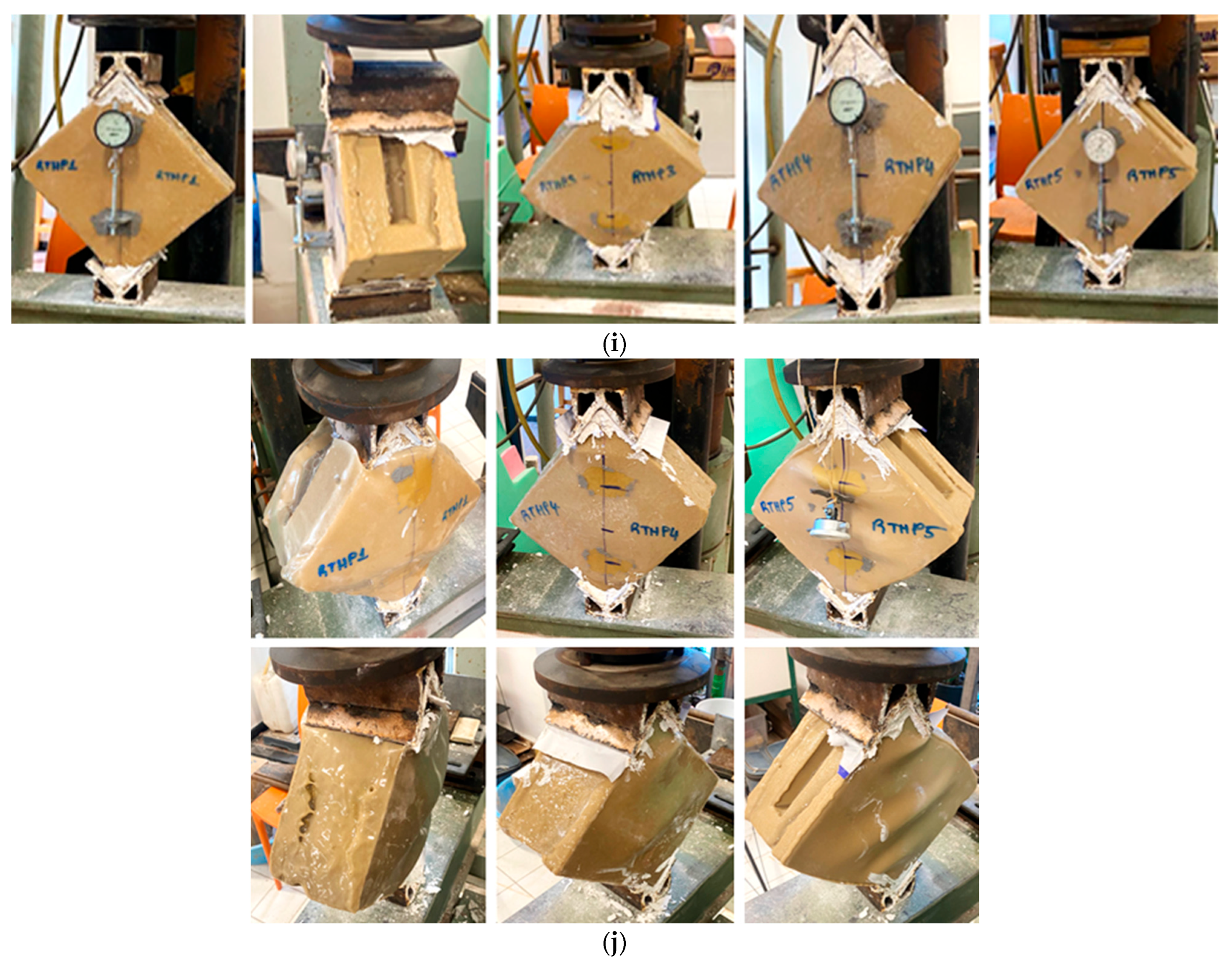
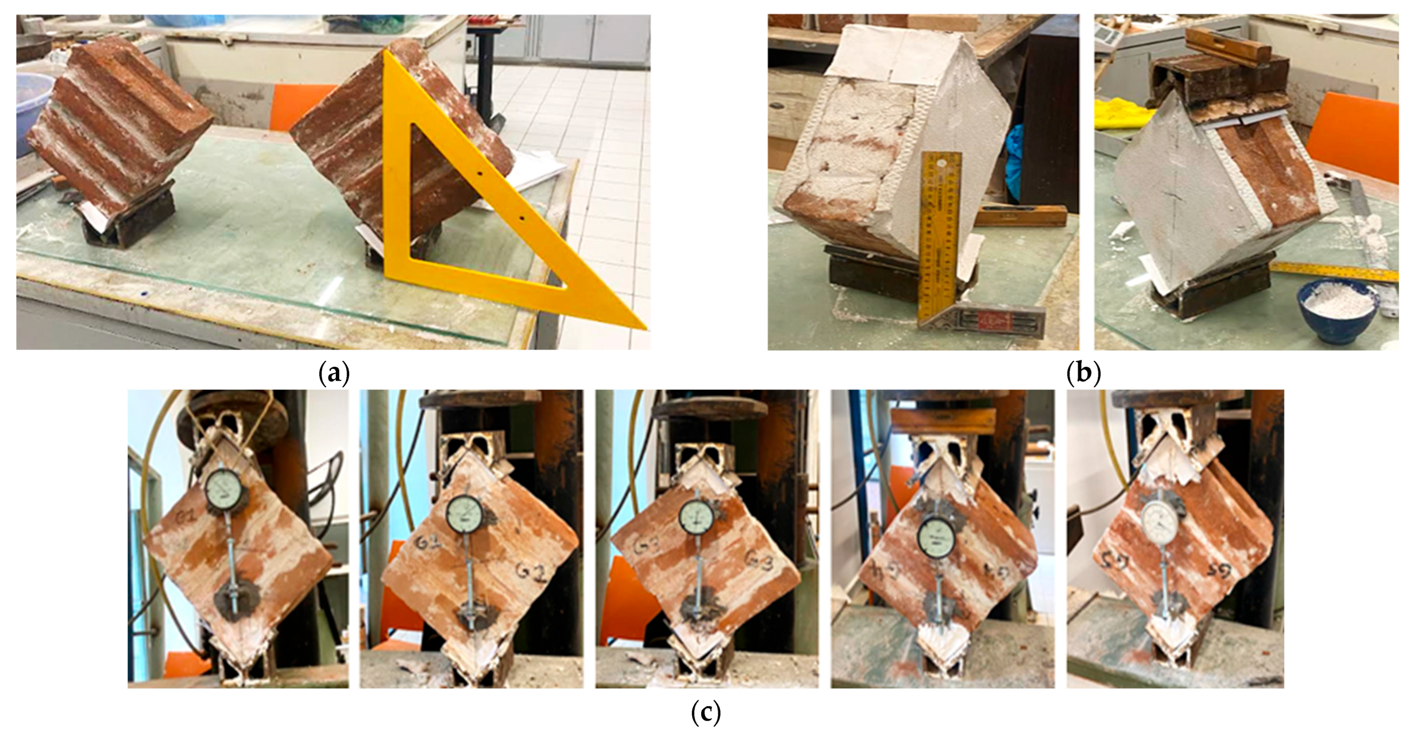
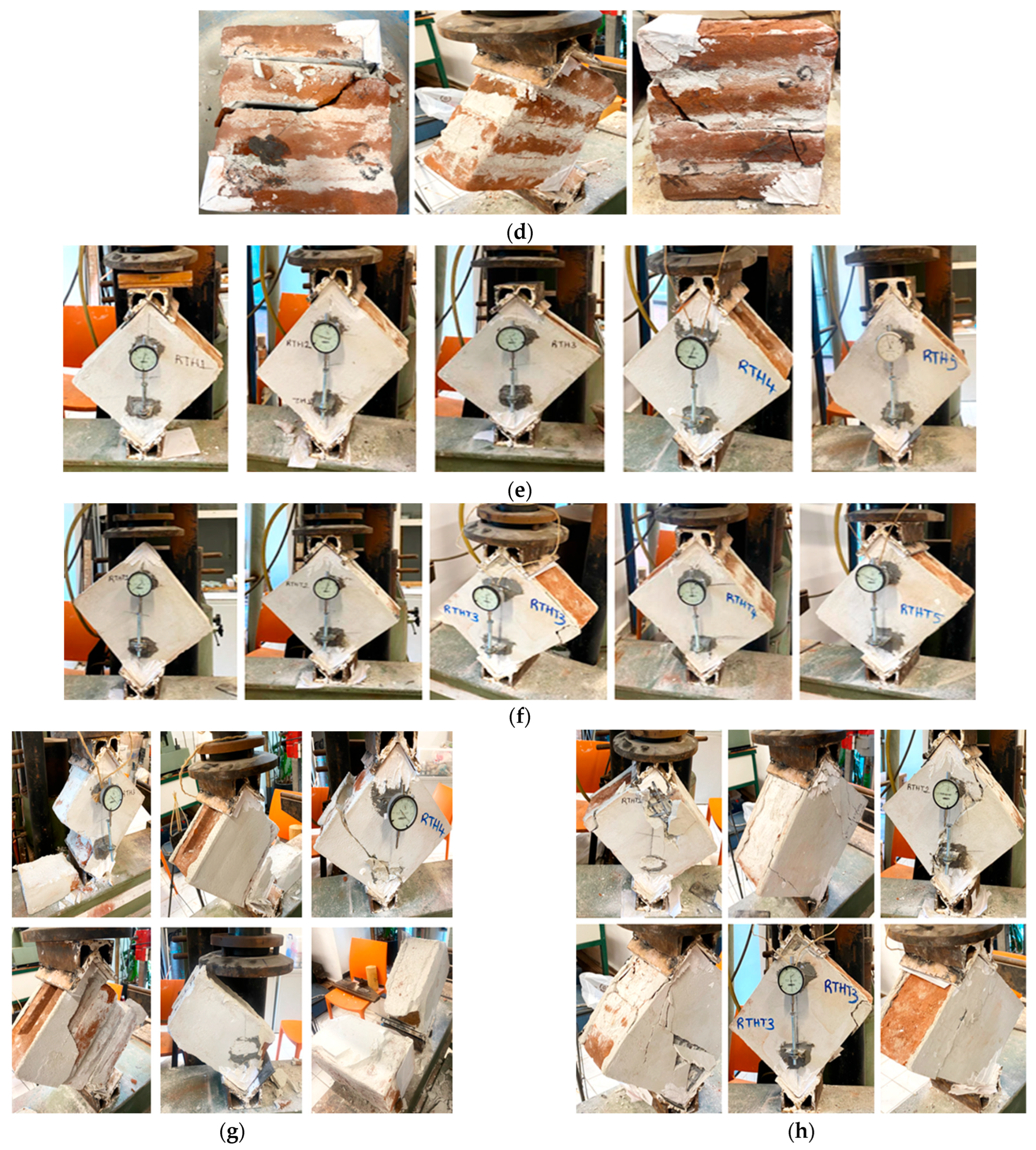
The failure mechanisms and cracks observed during the diagonal compression tests for all experimental groups are illustrated in
Figure 12.
The observed failure mechanisms varied significantly across the groups. G specimens reached an average maximum shear strength of 0.32 MPa and an average maximum shear strain of 1.68%. Failure was primarily characterized by debonding and displacement at the horizontal and vertical mortar joints. In G specimens, additional cracking within the brick units was observed, leading to collapse. Strengthening with RTH increased the mean shear strength to 0.36 MPa and the mean shear strain to 2.06%. Failure involved bidirectional separation at the mortar-brick interfaces and visible cracking on the RTH-strengthened surfaces. RTHT further enhanced the performance, attaining a mean shear strength of 0.47 MPa and a strain of 2.86%. These specimens exhibited bidirectional cracking in the RTH matrix with minor debonding; however, no ruptures were observed in the carbon textile fibers as the mesh effectively confined the mortar. RTHP demonstrated the highest performance, with an average shear strength of 0.80 MPa and an average maximum strain of 3.62%. Due to the hyper-elastic nature of the polyurea material, these specimens did not exhibit brittle fragmentation; instead, failure was dominated by localized crushing and significant swelling at the loading points. The shear modulus
) values for the reinforced groups provided a comprehensive baseline for comparison with existing TRM literature. While the addition of the RTHP system increased the initial shear stiffness by approximately 15.34% compared to the reference specimens, the RTHT group exhibited a slight reduction in shear modulus (approx. 14.24%). This variation indicates that while polyurea provides a balanced enhancement of stiffness and strength, the carbon textile-reinforced mortar (RTHT) primarily improves the system’s energy dissipation capacity by allowing for larger shear strains without inducing an undesirable over-stiffening effect. These results facilitate better alignment with standard TRM performance benchmarks where mechanical compatibility and ductility are prioritized over absolute stiffness [
29]. The outcomes of the diagonal compression tests are also performed in
Table 7.
To analyze the consistency of the diagonal compression tests, the statistical dispersion of the shear stress
was determined for the masonry wallets in
Table 7. While the control specimens (G) exhibited expected variability [
30,
35], the strengthened wallets—particularly the RTH and RTHP groups—demonstrated remarkable statistical stability with CoV values as low as 1.3–19.4%. This high level of consistency indicates that the proposed strengthening techniques effectively bridge the inherent flaws in the masonry substrate, providing a reliable and reproducible structural upgrade as supported by the literature on advanced composite applications [
16,
21,
25].
2.3.3. Tensile Adhesion Test on Polyurea Material
Tensile adhesion (pull-off) tests were conducted in accordance with the ASTM D4541 standard [
33]. The aim is to evaluate the bond performance and interfacial integrity of spray polyurea coating on the masonry substrate.
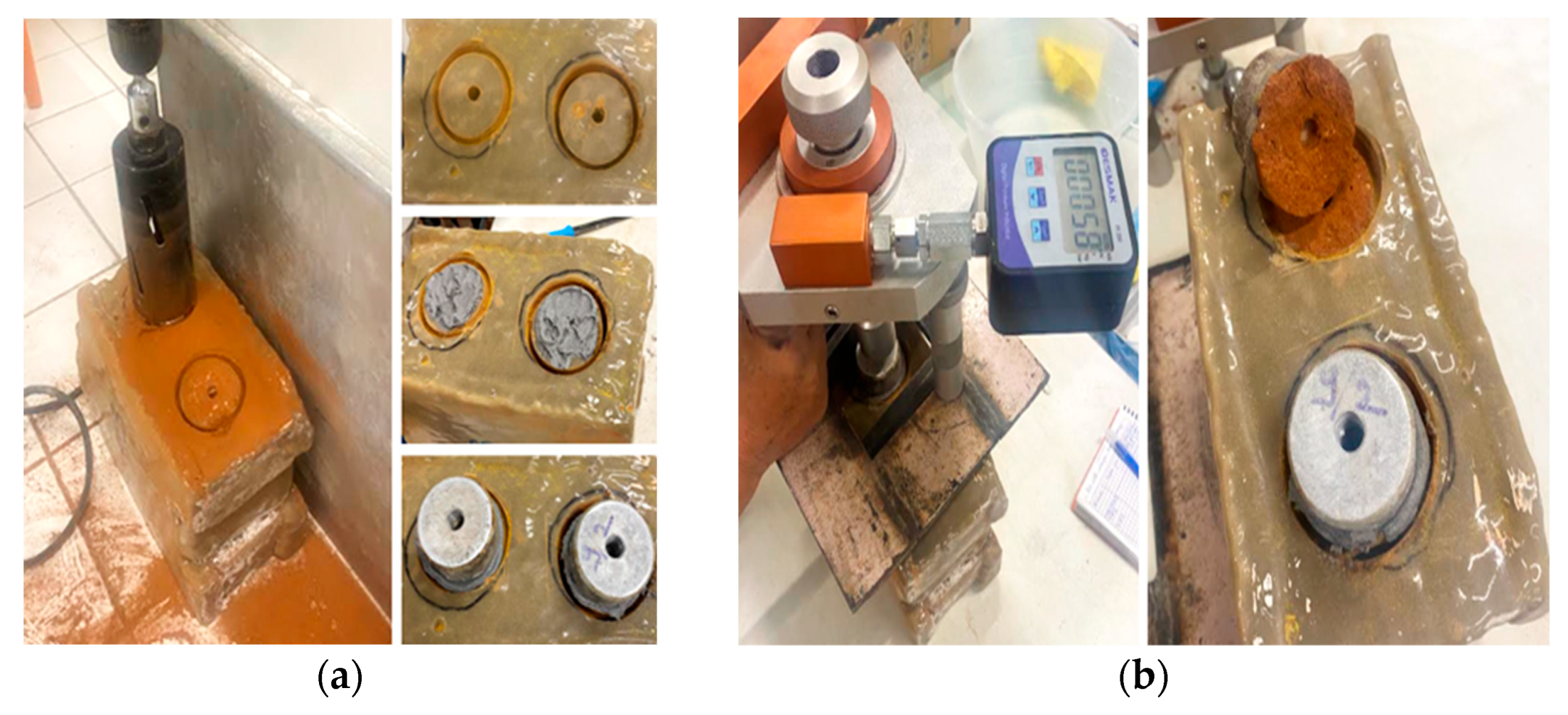
The adhesion strength was measured using a digital pull-off tester manufactured by Besmak (Ankara, Turkey). Six circular test areas were isolated from the RTHP strengthened specimens by core drilling through the polyurea layer. The test samples had a diameter of 56.40 mm, and an average thickness of 3.48 mm. Steel dollies were bonded to the isolated polyurea surfaces using a high-strength epoxy adhesive. A sufficient curing period was allowed to ensure that failure occurred at the polyurea-brick interface rather than within the adhesive layer. A monotonic tensile load was applied perpendicularly to the test surface at a constant rate until debonding occurred.
The adhesion strength (
) was calculated using Equation (7):
where
is the maximum tensile force at failure (N) and
is the contact area of the circular sample (mm
2). The physical appearance of the samples after core drilling and before the testing process is illustrated in
Figure 13. The results of pull-off tests conducted on six specimens to determine the bonding strength between spray polyurea and the masonry surface are summarized in
Table 8.
Spray polyurea exhibited high adhesion to the masonry surface. It was observed that the polyurea did not cause any brittle fragmentation or plucking of the brick units during the separation process. The absence of substrate failure (brick plucking) combined with the measured adhesion values suggests that the polyurea provides a flexible yet robust confinement. This characteristic supports the high shear strain capacity (3.62%) observed in the diagonal compression tests, as the material maintains interfacial integrity even under significant angular distortion. The compatibility between polyurea and historic brick substrates is ensured through both chemical and physical mechanisms. Chemically, the polyurea used is a solvent-free and inert elastomer, meaning it does not react with the mineral components of the handmade bricks or trigger efflorescence. Physically, its low elastic modulus allows it to accommodate the thermal expansion and hygroscopic movements of the historic masonry without inducing stress concentrations. While the measured average adhesion strength was 0.112 MPa, the failure mode is the primary indicator of this compatibility. The absence of brittle fragmentation or “brick plucking” indicates that the polyurea provides a flexible confinement that respects the fragile nature of the substrate. This interfacial integrity allows the strengthening layer to maintain its bond even under the high shear strains (3.62%) observed in the structural tests, confirming a harmonious mechanical interaction.
The measured average adhesion strength (0.112 MPa) and the cohesive failure within the brick units serve as quantitative indicators of the physical integration between the elastomer and the substrate. This experimental evidence, coupled with the material’s low modulus, confirms that the strengthening system accommodates the inherent movements of the historic masonry without inducing mechanical incompatibility.
3. Results and Discussion
3.1. Failure Loads of Brick Masonry Specimens
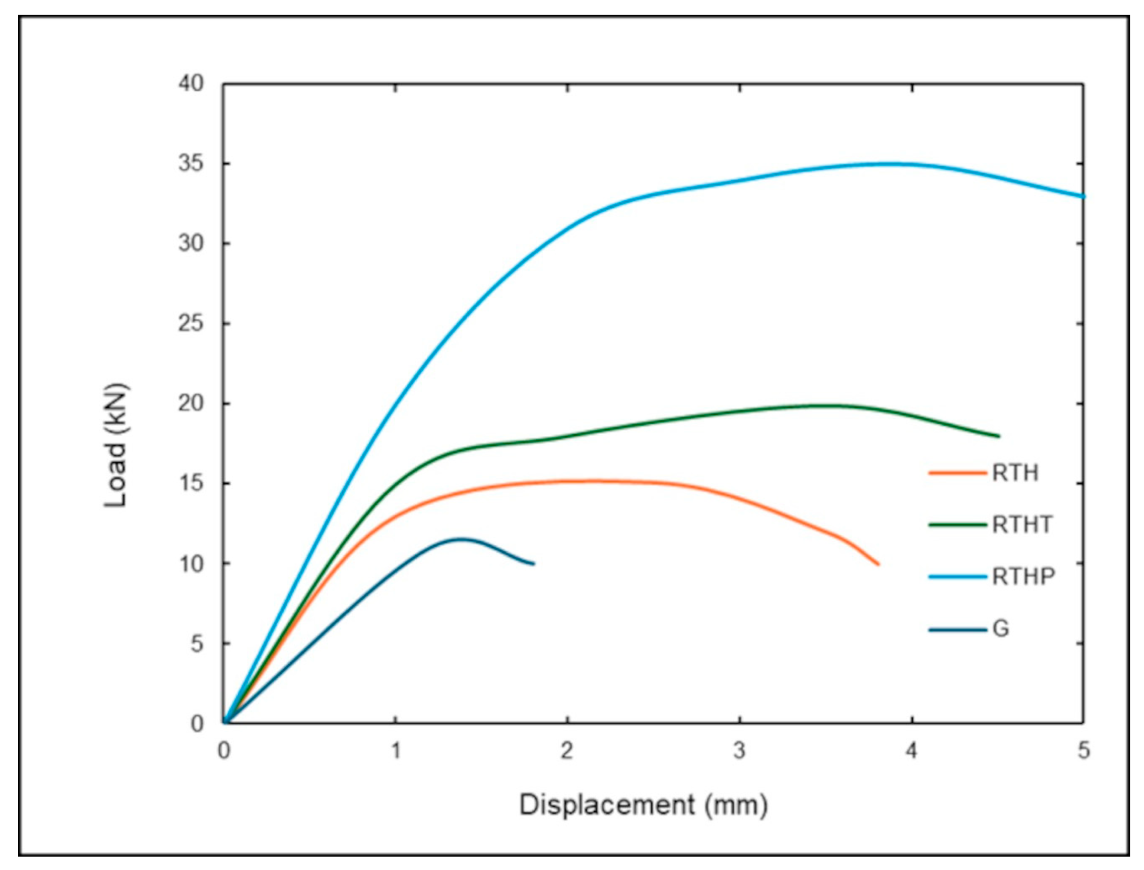
Failure loads of quadruplet brick masonry specimens under diagonal compression are presented in this section. The ultimate load-bearing capacities for each group were evaluated to determine the efficiency of the strengthening systems. The experimental results indicate that RTHP group significantly enhanced the load-bearing capacity compared to the unreinforced reference G group. As demonstrated in
Figure 14, the load-deformation curves highlight how the strengthening systems significantly alter the initial stiffness and peak load of the specimens. The RTH and RTHT groups exhibit a steeper linear elastic branch compared to the control group, indicating a substantial increase in stiffness due to the confinement provided by the restoration mortar and carbon textile. However, while the RTHT specimens reach the highest peak loads, they undergo a rapid strength degradation immediately after the peak, characteristic of a brittle failure mode. In contrast, the RTHP group exhibits a more stable post-peak behavior; although its initial stiffness is slightly lower than the RTHT group, it maintains structural integrity over much larger deformations. This transition from brittle to ductile behavior confirms that the polyurea layer prevents the sudden and catastrophic collapse observed in the other strengthened categories, as detailed in
Table 9 with the corresponding percentage increases.
The implementation of different strengthening strategies provided significant structural advantages compared to the unreinforced control group (G). The control specimens (G) exhibited a brittle failure mode with a mean peak load of 11 kN at a displacement of 1.2 mm, serving as the baseline for evaluating the strengthening systems. RTH specimens increased the mean failure load to 15.1 kN at a displacement of 2.5 mm, representing a 37.3% improvement over the G group. The RTHT group further enhanced its capacity to 19.9 kN, achieving an 80.9% increase at a displacement of 3.4 mm compared to the G group. The most substantial enhancement was observed in the RTHP group, which reached a mean peak load of 35 kN at a displacement of 4.0 mm. This configuration provided a remarkable 218.2% increase in load-bearing capacity compared to the unreinforced specimens. The RTHP group achieved a remarkable 218.2% increase in load-bearing capacity compared to the unreinforced specimens. To verify the reliability of this substantial enhancement, statistical variability was analyzed as shown in
Table 9. The coefficient of variation (CoV) for the RTHP group was notably low (1.3%), confirming that the observed strength gains are highly consistent across the specimens and are not skewed by extreme average values. The high performance of the RTHP group is attributed to the polyurea layer acting as a ductile membrane that effectively confines the masonry units. Even after initial cracking, the polyurea maintained the integrity of the wallet, preventing the disintegration of the brick units and allowing the specimen to sustain significantly higher loads.
3.2. Shear Stress–Strain Relationship of Brick Masonry Specimens
According to the average shear stress results presented in
Table 10, all strengthening strategies provided superior performance compared to the unreinforced control specimens (G). The specimens strengthened with restoration mortar RTH exhibited a 12% increase in shear stress. A more significant improvement was observed in the restoration mortar and carbon textile-reinforced RTHT specimens, with a 46% increase. This enhanced performance in RTHT specimens is attributed to the presence of textile reinforcement, which bridges cracks and improves load distribution under diagonal compression, thereby enhancing ductile behavior.
The most prominent enhancement was recorded in the specimens reinforced with restoration mortar and sprayed polyurea RTHP, which showed a 151% increase in shear stress compared to the control group. The RTHP configuration showed a 151% increase in shear stress compared to the control group. The statistical robustness of this improvement is evidenced by the minimal variation (CoV of 1.3%) reported in
Table 10, demonstrating the high reproducibility of the polyurea-based strengthening system. Furthermore, the shear stress of the RTHP group was 71% higher than that of the RTHT group. This remarkable increase is closely related to the hyper-elastic nature and high tensile strength of the polyurea material. Consequently, while the unreinforced masonry specimens exhibited the lowest shear strength, the RTHP configuration achieved the highest shear stress capacity.
The average vertical strain values and their respective increase rates are summarized in
Table 11. The experimental results indicate that the vertical strain capacity increased by 23% for RTH, 70% for RTHT, and 115% for RTHP compared to the unreinforced specimens. The statistical reliability of these findings is supported by the low variation observed in the RTHP group (CoV of 2.2%), which confirms that the significant enhancement in deformability is a consistent result of polyurea-based strengthening, rather than a misleading average derived from scattered data. Notably, the RTHP group exhibited a 26% higher vertical strain than the RTHT group. Among the strengthened specimens, the RTH configuration provided the minimum improvement in deformability. However, the integration of carbon textile and sprayed polyurea significantly enhanced the strain capacity. Higher strain values under diagonal compression signify a more ductile and flexible structural response [
51,
52]. In conclusion, the polyurea-reinforced RTHP specimens demonstrated superior ductility compared to the carbon textile-reinforced RTHT specimens, effectively transforming the brittle masonry behavior into a more resilient and deformable state.
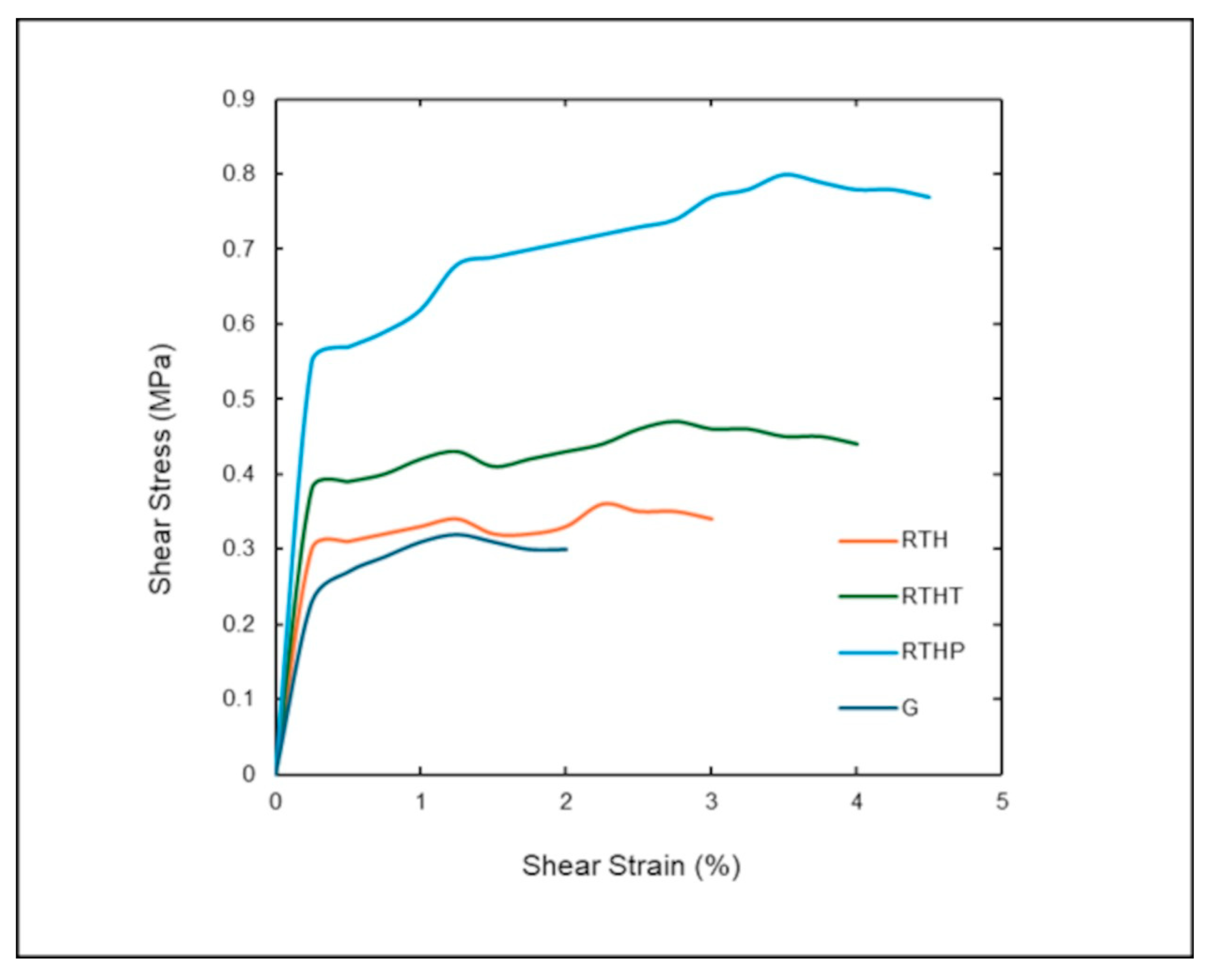
The structural ductility and the post-peak behavior of the tested masonry wallets are further evaluated through the shear stress–strain relationships.
Figure 15 illustrates the comparative performance of the unreinforced and strengthened specimens, highlighting the transition from brittle failure to a controlled, ductile response.
The stress–strain curves provide a clear representation of the mechanical enhancement achieved. All strengthened groups exhibited an initial stiffness comparable to or higher than the reference group G. However, RTHP specimens maintained their linear elastic phase over a wider strain range before reaching the yield point. While the control specimens failed abruptly shortly after reaching their peak stress, the RTHP system displayed a significant “ductile plateau.” The area under the curve for RTHP group is considerably larger than that of the other configurations, signifying a superior energy dissipation capacity as a crucial parameter for seismic resilience. The steady post-peak performance in
Figure 15 for the RTHP group confirms the effectiveness of the polyurea strengthening. This elastomeric layer acts as a containment membrane that resists diagonal tension and holds the cracked masonry units together, thereby preventing a catastrophic loss of strength. As illustrated in
Figure 15, the comparative analysis of the shear stress–strain curves reveal distinct mechanical hierarchies among the strengthening strategies. Regarding stiffness, the initial slopes of the RTH and RTHT groups are steeper than the control group G, indicating that the rigid restoration mortar and carbon textile provide high early-stage resistance. In terms of strength (load capacity), while all methods outperformed the control specimens, the RTHT group provided a significant strength increase (46%) but failed abruptly after reaching its peak. The most critical differentiator is ductility and energy dissipation. The RTHP group not only achieved the highest shear stress capacity (151% increase) but also maintained its structural integrity over a remarkably wider strain range. Unlike the brittle failure of the G and RTH groups, or the limited post-peak capacity of the RTHT group, the RTHP specimens exhibited a “ductile plateau.” This confirms that the hyper-elastic polyurea transforms the masonry from a brittle state into a highly deformable system, which is essential for seismic resilience where energy absorption is as critical as peak strength.
3.3. Interpretation and Comparative Analysis of Strengthening Mechanisms
The experimental results clearly demonstrate that the strengthening techniques significantly influenced the structural behavior of the masonry specimens in terms of load capacity, deformation capacity, and failure mechanisms. The unreinforced masonry specimens exhibited typical brittle behavior, characterized by sudden crack propagation along mortar joints and brick interfaces. This behavior is consistent with the well-known quasi-brittle mechanical nature of historic masonry, which possesses high compressive strength but very limited tensile and shear resistance.
The application of restoration mortar (RTH) improved the overall structural performance primarily by enhancing the bond between masonry units and by providing a uniform surface layer that distributed stress across the masonry surface. The increase in shear capacity observed in the RTH group can therefore be attributed to the improved interlocking between the mortar and brick surfaces as well as the confinement effect provided by the additional mortar layer. However, the structural improvement achieved with RTH alone remained relatively limited compared with the composite strengthening systems. This observation indicates that surface mortar layers without reinforcement mainly act as crack-control and surface stabilization mechanisms rather than providing significant tensile resistance.
The integration of carbon textile reinforcement (RTHT) significantly increased the load-bearing capacity and stiffness of the masonry specimens. The carbon textile mesh embedded within the restoration mortar created a composite reinforcement system capable of transferring tensile forces across cracks. As a result, crack propagation was partially controlled by the textile fibers, preventing immediate failure after initial cracking. Despite the improved strength, RTHT specimens still exhibited relatively brittle failure patterns characterized by cracking within the mortar matrix and partial debonding between the reinforcement layer and masonry substrate. This behavior is typical for Textile Reinforced Mortar (TRM) systems, which rely on the tensile strength of fibers but remain limited by the stiffness and cracking behavior of the mortar matrix. Similar improvements in crack control and load-bearing capacity have also been reported in previous studies on Textile Reinforced Mortar TRM strengthening systems applied to masonry structures.
In contrast, the spray polyurea strengthening system (RTHP) demonstrated a fundamentally different mechanical response. The polyurea layer acted as a highly ductile elastomeric membrane capable of accommodating large deformations while maintaining strong adhesion to the masonry surface. Instead of transferring loads through fiber reinforcement, the polyurea coating functioned as a continuous confinement layer that restrained crack opening and prevented the sudden detachment of masonry fragments. This mechanism explains the significant increase in both shear strength and deformation capacity observed in the RTHP specimens. The RTHP group achieved a remarkable 218.2% increase in load-bearing capacity compared to the unreinforced specimens. To verify the reliability of this substantial enhancement, statistical variability was analyzed. The coefficient of variation (CoV) for the RTHP group was notably low (1.3%), confirming that the observed strength gains are highly consistent across the specimens and are not skewed by extreme average values. Similarly, the RTHP configuration showed a 151% increase in shear stress. The statistical robustness of this improvement is evidenced by the minimal variation (CoV of 1.3%) reported in
Table 10, demonstrating the high reproducibility of the polyurea-based strengthening system. The hyper-elastic nature of polyurea allowed the masonry assembly to undergo large strains before failure, effectively transforming the brittle behavior of masonry into a more ductile structural response. This ductile behavior is consistent with previous research highlighting the high strain capacity and energy absorption potential of polyurea-based coatings used for structural protection.
The experimental results indicate a clear hierarchy in the effectiveness of the investigated strengthening techniques. Restoration mortar strengthening (RTH) increased the average shear strength from approximately 0.16 MPa in the control group to 0.26 MPa. The addition of carbon textile reinforcement (RTHT) further increased the average shear strength to approximately 0.40 MPa. The most significant improvement was achieved with the spray polyurea system (RTHP), which reached an average shear strength of 0.61 MPa in the shear tests and approximately 0.80 MPa in the diagonal compression tests. The shear strength increments observed in this study were compared with similar reinforcement techniques in the literature to validate the performance of the proposed systems. For the RTHP (Polyurea) group, the diagonal shear strength increase of 150–218% is consistent with the findings of García-Ramírez et al. [
21], who reported significant enhancement in masonry confinement using elastomeric coatings. However, the RTH (Restoration mortar) group showed a lower performance (+62%) compared to some TRM studies that utilize high-strength cementitious mortars. This discrepancy can be attributed to the mechanical properties of the mortar used in this research. While industrial TRM systems often rely on M15 or M20 grade mortars, this study intentionally employed a low-modulus restoration mortar to ensure physicochemical compatibility with the fragile, historic handmade bricks. While this choice results in lower peak stress increments, it prevents the common ‘stiffening’ failure modes seen in more rigid TRM applications, thereby prioritizing the long-term integrity of the historic substrate over absolute strength gain. These results highlight the different mechanical roles of strengthening systems.
The RTH system primarily enhances surface integrity and bonding, leading to moderate improvements in strength. The RTHT system introduces tensile reinforcement capable of bridging cracks and increasing the load-bearing capacity of the masonry assembly. However, the polyurea system functions through a different strengthening mechanism based on elastic confinement and energy dissipation. The superior performance of the polyurea strengthening system can therefore be attributed to three main factors: High deformation capacity of the elastomeric material, Continuous confinement effect provided by the membrane, and Strong adhesion to the masonry substrate. Similar trends have been observed in previous studies comparing fiber-based strengthening systems with elastomeric coatings, where materials with higher deformability often provided improved energy dissipation capacity. Unlike fiber-reinforced systems, the polyurea coating distributes stress across the entire masonry surface rather than concentrating them along reinforcement directions. This leads to a more uniform stress distribution and reduces the likelihood of localized brittle failure.
3.4. Failure Mechanisms and Ductility Behavior
One of the most significant findings of this research is the substantial change in failure mechanisms observed in the strengthened masonry specimens. Unreinforced specimens exhibited brittle cracking patterns along mortar joints and brick interfaces, often followed by sudden separation of masonry units. This type of failure is commonly observed in historic masonry structures subjected to shear loading.
In RTH-strengthened specimens, cracking patterns were mainly distributed along the added mortar layer. Although the additional mortar provided partial confinement, the overall structural behavior remained relatively brittle. RTHT specimens exhibited improved crack control due to the presence of carbon textile reinforcement. The textile fibers successfully bridged cracks within the mortar matrix and delayed the propagation of major cracks. However, failure eventually occurred due to cracking within the mortar layer or local debonding of the reinforcement system.
The behavior of the polyurea-strengthened specimens differed significantly from the other systems. Instead of brittle cracking and fragmentation, the specimens exhibited large deformations accompanied by localized crushing at the loading points. The polyurea membrane remained intact even after significant deformation of the masonry substrate.
The substantial increase in load-bearing capacity (+218% for RTHP) compared to the modest pull-off strength (0.112 MPa) suggests a shift in the primary strengthening mechanism. While the adhesion strength is sufficient to initiate composite action, the ultimate structural performance is governed by a “confinement effect” rather than pure interfacial bond. As the masonry substrate reaches its tensile limit and begins to crack, the polyurea coating functions as a continuous elastomeric membrane. Due to its high elongation capacity and tensile strength, the coating bridges the macro-cracks and prevents the disintegration of the brick units. This mechanism transforms the brittle masonry failure into a more pseudo-ductile response, where the polyurea “contains” the internal damage and redistributes the stresses over a wider area. Therefore, the low bond strength does not limit the structural gain because the system relies on the membrane’s tensile resistance to maintain the integrity of the wall during large diagonal displacements.
To provide a quantitative basis for the observed ductile response, the displacement ductility index (μ) was calculated for each group using Equation (8) [
53]:
where
is the ultimate displacement corresponding to a 20% degradation of the peak load, and
is the yield displacement determined by the bi-linear idealization of the load-deformation curves in
Figure 14. Based on this analysis, the RTHP group achieved a ductility index of approximately 3.33, representing a significant improvement over the RTHT (
≈ 1.36) and RTH (
≈ 1.25) groups. Furthermore, the post-peak behavior was quantified through residual strength analysis. While the unreinforced specimens (G) exhibited a total loss of capacity immediately after the peak, the RTHP group maintained a residual strength of approximately 85% of its peak stress even at high strain levels, confirming superior energy dissipation through a stable plateau in the stress–strain relationship previously illustrated in
Figure 15.
This behavior indicates that the polyurea coating effectively prevents sudden fragmentation of masonry elements and allows the structure to dissipate energy through deformation. Such behavior is particularly beneficial for masonry structures subjected to dynamic loading conditions such as seismic events. Such ductile behavior is particularly advantageous for masonry structures located in seismic regions, where energy dissipation and deformation capacity play a critical role in structural safety.
3.5. Implications for Conservation of Historic Masonry
From the perspective of structural conservation, strengthening interventions should ideally improve structural performance while minimizing the impact on the original historic fabric. Traditional strengthening methods such as reinforced concrete jacketing or steel frames often introduce significant additional stiffness and weight, which may lead to incompatibility with historic materials. In contrast, the strengthening techniques investigated in this study represent relatively lightweight and surface-based interventions.
Restoration mortar and TRM systems are widely accepted in conservation practice due to their mineral-based compatibility with historic masonry materials. However, the results of this study indicate that elastomeric coatings such as polyurea may also offer significant advantages in terms of ductility and energy dissipation.
Although polyurea is a synthetic material, its thin application thickness and non-intrusive installation process make it a potentially viable strengthening solution for historic masonry structures. In particular, the ability of polyurea coatings to prevent brittle fragmentation may contribute to improved structural safety during seismic events. Nevertheless, the long-term durability, vapor permeability, and compatibility of polyurea systems with historic masonry require further investigation before widespread application in heritage conservation projects. Therefore, the findings of this study contribute to the growing body of research investigating innovative strengthening techniques aimed at improving the seismic resilience of historic masonry structures.
3.6. Limitations of the Study and Future Research
While the experimental results provide valuable insights into the structural performance of the investigated strengthening systems, several limitations should be acknowledged to ensure a rigorous interpretation of the data. First, the experimental program was conducted on relatively small masonry wallet specimens (220 × 245 × 100 mm). These “element-level” samples are effective for evaluating the relative efficiency of different coating materials and their interfacial bond behavior. However, they may not fully capture the complex, multi-axial stress distributions and global failure mechanisms—such as rocking, sliding, or toe-crushing—typically observed in full-scale masonry walls. In smaller specimens, the ratio of the reinforcement thickness to the substrate volume is higher than in real-world structures, which might lead to a localized overestimation of the confinement effect. Therefore, the strength increases reported in this study should be interpreted as comparative performance metrics rather than absolute design values for large-scale structural interventions. The influence of boundary conditions in small-scale tests differs from that of integrated structural systems. While our laboratory conditions (20 ± 2 °C and 65 ± 5% RH) were strictly controlled, full-scale structures are subject to varying environmental and loading redistribution mechanisms that could affect the long-term interaction between the polyurea and the masonry. Third, the study focused primarily on monotonic loading conditions. The behavior of polyurea-strengthened masonry under cyclic or dynamic loading conditions, such as seismic actions, remains an important topic. Future research involving large-scale wall panels and numerical homogenization techniques is necessary to calibrate these element-level findings for global seismic retrofitting applications.
In summary, future studies should focus on:
Cyclic and seismic loading behavior of large-scale panels;
Long-term durability of polyurea coatings under actual environmental exposure;
Numerical modeling of scale effects for masonry-polyurea composites.
Such investigations would contribute to a more comprehensive understanding of the potential of polyurea-based strengthening systems for historic masonry structures.