Abstract
The ground settlement induced by shield tunnel construction should be carefully monitored and controlled during construction as a compulsory measurement to ensure construction safety. In the existing literature, gap parameter theory is adopted to predict ground settlement; however, the influence of slurry grouting on ground settlement during the construction process has been ignored. Regarding this drawback, a novel optimized gap parameter theory is proposed and combined with 3D finite element analysis to investigate ground settlement caused by shield tunnel excavation. Considering that construction technology plays an important role in ground settlement, numerical studies are carried out to investigate the sensitivities of the grouting filling ratio, pressure of the tunnel face, and the strata conditions in ground settlement. The practical engineering of Wuhan Metro Line 7 is introduced to verify the superiority of the proposed method. The results show that the proposed method can reflect ground settlement well, compared to the existing methods and the measured data. Then, 3D finite element analysis and orthogonal test are adopted to conduct sensitivity analyses of the grouting fill rate, support pressure ratio, and strata conditions. The results illustrate that the grouting filling rate has the most obvious impact on ground settlement, while the support pressure ratio and strata conditions also have a certain impact on ground settlement. Taking the binary structure stratum of the terrace geological environment of the Yangtze River in Wuhan as the research object, this study employs a three-dimensional numerical simulation approach to analyze six distinct binary structure stratum models. The parameter value ranges, considering formation conditions, are determined through integrated theoretical analysis. Finally, based on the deviation analysis results between the optimized gap parameter theory and numerical simulation, it is concluded that there is no significant difference in the surface settlement values obtained from the two methods. To summarize, the proposed optimized gap parameter theory, combined with the corresponding numerical simulation technology, provides a good tool for the control of ground settlement caused by shield tunnel excavation in complex strata, such as binary structure strata.
1. Introduction
With the development of urbanization, urban transportation construction has also tended to be more complex and sophisticated. In underground engineering construction, tunnels play a critical role in such structures and demonstrate superiority over other components. Shield construction has been broadly used due to its demerits, such as wide applicability, high mechanization and construction efficiency, limited impact on the environment, no environmental and climate restrictions, and methodological maturity. It has gradually become the main construction method for dealing with complex and difficult geological conditions, such as soft strata and crossing rivers and seas [1,2]. Ground settlement during shield tunnel excavation is an important issue in tunnel design and feasibility analysis. Although the existing construction technologies for shield tunnels are becoming increasingly sophisticated, and the number of shield tunnels is increasing yearly, settlement prediction in most construction still relies on experience.
Regarding the ground settlement prediction, the commonly used empirical formula, i.e., Peak formula [3], can predict regional ground settlement based on local monitoring data. However, it strongly relies on the measured data and cannot consider the complex strata conditions and construction factors, resulting in limited prediction accuracy. The numerical simulation method [4] can comprehensively consider the shield construction process, especially for more complex construction technology, and can conduct effective simulations. Lou et al. [5] used the 3D finite element software ABAQUS to consider the influences of the tunnel excavation slope, grouting pressure, and shield tail gap on ground settlement. Ye et al. [6] studied the effects of grouting pressure, tail brush pressure, and pore water pressure on the lining pressure in shallow-covered shield tunnels across rivers, using experimental monitoring and numerical simulation. The above research considered the influence of the grouting process on ground settlement by using numerical simulation methods, but only focused on grouting pressure, without considering the influence of grouting filling degree. Chakeri and Ozcelik [7] studied the influence of factors such as tunnel depth and face pressure on ground settlement through theory and numerical simulation. However, the study only considered the pressure at the face and did not analyze the mutual force relationship between the pressure at the face and the supporting pressure. The discrete element method (DEM) is also a common means of solving geotechnical engineering problems due to the advantages of simulating discontinuous media and large deformation [8]. However, the current discrete element method is unsuitable for widespread use because of its large flow rate. Furthermore, the physical model test can better simulate the complex tunnel construction environment [9,10,11], but its high cost and long operation time set barriers for its application.
Based on the gap parameter concept proposed by Lee and Rowe et al. [12], and in combination with the three-dimensional finite element method, this paper presents an optimized gap parameter theory. This theoretical approach aims to integrate the advantages of the above two technologies, enhancing the accuracy and reliability of surface deformation prediction. Gap parameter theory addresses three-dimensional stratum loss issues using a two-dimensional gap concept. Its characteristic is that it considers the influence of tunnel construction technology on the stratum. However, the traditional gap parameter theory still has deficiencies in considering soil deformation characteristics and the impact of construction technology, especially in its inability to effectively combine with the synchronous grouting process in shield construction. Moreover, many theoretical studies focus on a single stratum and do not consider the influence of multi-layer strata on ground settlement during shield construction. This paper analyzes the settlement problems caused by tunnel excavation based on three main construction factors: the grouting filling ratio β, support pressure ratio λ, and eccentricity κ during shield construction. Taking the shield tunnel excavation project of the Wuhan Metro Line 7 as a case study, it analyzes the surface deformation problems caused by shield construction in complex stratum environments, such as the Yangtze River terrace area [13,14]. It introduces a parameter that considers the influence of multiple strata on ground settlement and determines the applicable range of this parameter through three-dimensional numerical simulation methods. The main purpose of proposing this theory is to provide a more effective theoretical basis and technical support for the control of surface deformation during shield tunnel construction, thereby reducing the impact of construction on the surrounding environment and ensuring the safety and stability of the project.
2. Ground Settlement Prediction Theory
Empirical methods are the most typical and classical ways to predict ground settlement in tunnel engineering. According to Peak’s formula [15,16], it assumes that the loss of ground caused by tunnel excavation, without drainage, can be approximately measured by soil loss at the surface, and the surface lateral deformation obeys a normal distribution, which is described in Figure 1. Ground settlement evaluation based on Peak’s formula can be described as follows:
where is the ground settlement at the position x; is the maximum settlement above tunnel axis; x is the lateral horizontal distance from the tunnel axis; R is the excavation diameter; is the width coefficient of the ground settlement groove; is the unit soil loss volume; and is the theoretical ground loss ratio. Here, it should be noted that and are usually evaluated by the least squares method, based on the measured data. Many measured data points in the same area can be fitted to obtain the range of the empirical parameters in this area. Then, the ground settlement caused by tunnel excavation under similar geological conditions in the area can be predicted. Due to various geological conditions from area to area, the tunnel construction results are different. In some excavation cases, the settlement can reach up to 40% of the excavated tunnel volume [17]. Furthermore, some scholars have conducted studies on tunnel shield construction process parameters, excluding the geological empirical parameters. Based on Lee’s gap parameter formula, Zhu et al. [18] proposed an approach to quantify ground settlement, which determines the grouting filling rate, eccentric excavation, and balance pressure at the tunnel face as critical variables. However, there are some limitations in the consideration of the construction process. Zhang [19] proposed a surrogate layer theory to simulate the grouting-filled area in a 3D numerical simulation of shield tunnel excavation, which was formed based on the mixture of the grouting body and soil layer, however, the parameters of the surrogate layer need to be deduced on the basis of the measured data. In this study, gap parameter theory is adopted as a theoretical basis, and then combined with three-dimensional finite element analysis to analyze the ground settlement problem caused by tunnel excavation.
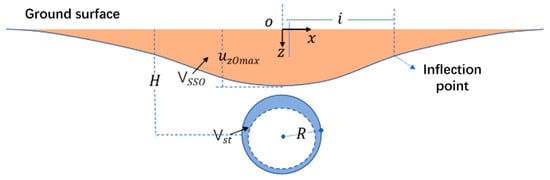
Figure 1.
Theoretical model for ground settlement calculation.
2.1. Gap Parameter Theory
In the study by Rowe et al. [20], the three-dimensional tunnel deformations, such as elastic–plastic deformation in the excavation face, over-excavation around the shield machine, and the physical gap between the shield machine and the lining, are equated to a two-dimensional gap, which can be described by the concept of the gap parameter. Then, according to the analytical model proposed by Rowe and Lee [12], the gap parameter without drainage can be calculated as follows:
where is the physical gap; is the 3D elastic deformation at the tunnel excavation face; denotes the construction technology level; is the axial squeeze at the tunnel excavation face; is a dimensionless deformation coefficient related to the tunnel stability factor ; stands for the strain radial displacement on the plane; expresses the tunnel radius; is the Young’s modulus of the soil at the tunnel footing, , when the undrained condition is met; is total stress removed at the tunnel excavation face; is the effective static soil pressure coefficient; is the vertical effective stress at the tunnel footing; is the pore water pressure at the tunnel footing before excavation; is the support force at the excavation face; is Poisson’s ratio under undrained conditions; and are the natural weight of the covered soil and the shear strength under undrained conditions, respectively; and is the distance from the tunnel centerline to the ground surface.
The abovementioned content indicates that gap parameter theory mainly focuses on three factors: (1) the mechanical gap at the shield tail of the shield machine, (2) the soil axial squeeze gap caused by imbalance pressure at the tunnel face during tunnel excavation, and (3) the radial tunnel displacement during tunnel excavation. Furthermore, the construction technology level is a complement to the impact of the above factors. However, with the development of construction process technology, the grouting process has gradually become a more obvious factor in gap parameters. Meanwhile, Rowe and Lee [12] believed that timely grouting in hard ground conditions can completely offset the physical gap, but the stratigraphy-related factors are ignored in the proposed formula. However, the stratigraphic environments in most shield construction cases are complex, especially in soft ground geological conditions. Additionally, solid stowing cannot be achieved in actual construction due to leakage and hardening of the slurry. Thus, the stratigraphic environment plays an influential role in the construction technology level, which cannot be ignored in the ground settlement evaluation formula. In this regard, this study aims to improve the theory of Rowe and Lee [12] by introducing the 3D finite element method. Moreover, the influence of the grouting fill ratio on the construction technology level is studied by introducing the grouting fill rate parameters and the support pressure ratio λ. Referring to Equation (10), the support pressure ratio λ can be calculated as follows:
Here, to consider the different influences in stratigraphic environments on the grouting fill rate, is introduced to the construction technology level , which is determined according to the various stratigraphic environments. And the range of is selected based on the subsequent simulation comparative study. To summarize, the modified construction technology level can be described as follows:
Furthermore, according to Equation (4), the gap parameter eventually is determined by the sum of , as the physical gap and gap caused by construction. is related to the balance force at the tunnel face, and thus, the gap parameter can be calculated as follows:
2.2. Ground Settlement Analysis
According to the study by Loganathan and Poulos [21], the analytical solution of ground settlement, considering the gap parameter, can be calculated based on the following equation:
where is the vertical displacement at the surface; is Poisson’s ratio; is the radius of the tunnel; is the horizontal distance from the centerline of the tunnel; is the gap parameter; and is the distance from the center axis of the tunnel to the ground surface. The Wuhan Metro Line 7 tunnel is taken as an example. Based on Equation (15), the ground settlement caused by the gap generated during shield construction is quantitatively analyzed with the measured data. Referring to the data of the interval section from Hong Kong Road to Sanyang Road, the working condition at ring 551 on the tunnelling excavation route is selected as the research object. The geological conditions of the area are shown in Figure 2, and the transverse ground settlement data are shown in Table 1.
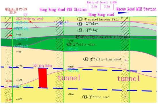
Figure 2.
Geological profile of the selected section in the Wuhan Metro Line 7 tunnel.

Table 1.
Monitoring data on cumulative surface settlement during tunnel construction.
From the geological profile of the selected section, the selected section is a binary stratigraphic structure, the upper soil is clay, the bottom is fine-grained soil, and the bearing layer is a fine sand layer. This project employs the slurry shield (SPB), which is more suitable for the complex terrace geological environment where Wuhan Metro Line 7 is located. According to the tunnel construction situation and the results of indoor and outdoor tests, the parameters of this section are as follows: (1) the tunnel axial depth H = 20 m, the shield tunnel excavation outer diameter D is about 6.45 m, the lining outer diameter is 6.2 m, the length of shield machine L = 9.0 m, and the theoretical gap parameter ; (2) under undrained conditions, the deformation modulus , Poisson’s ratio , the natural weight γ = 18.3 kN/m3, the shear strength , and the angle of internal friction is 8°; and (3) according to the monitored ground settlement data and underground tunnel, inverse analysis is carried out to obtain the construction process parameters, and the grouting filling ratio β is taken as 90%. Based on the above situation, the pressure at the tunnel face is basically balanced; thus, the pressure ratio coefficient λ can be determined as 0.93. Accordingly, the 3D elastic deformation is , and the maximum deformation of the tunnel face is . Thus, , according to the previous equation. To summarize, the optimized gap parameter can be calculated as follows:
Furthermore, the gap parameter, calculated by the formula from Rowe and Lee [10], is (without consideration of the grouting fill ratio). Then, the two gap parameters can be input to Equation (15) to obtain the corresponding ground settlement curves. After that, the ground settlement curves, calculated by the optimized gap parameter, original gap parameter, and Peak formula (ground loss rate = 2.3% and settlement trench width K = 0.7 [22]), are illustrated to make a comparison with the measured data, which are shown in Figure 3.
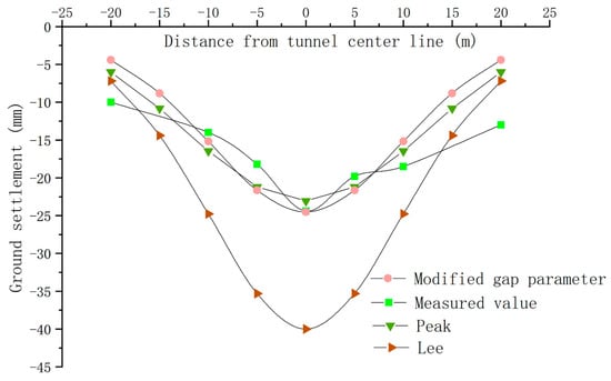
Figure 3.
The comparative curves of the gap parameters, based on the different calculation methods.
From the comparative results, the settlement calculated by Lee’s method is larger, which can be explained by the ignorance of the grouting factor. Additionally, the proposed optimized gap parameter equation, combined with the Loganathan formula, can achieve a settlement curve that is consistent with the measured curve. Furthermore, the result from the Peak formula is calculated based on the measured data, and thus, it is more consistent with the measured data than Lee’s method. In summary, the optimized gap parameter formula can better evaluate the ground settlement caused by shield excavation under the conditions of known construction factors, such as the grouting, tunnel face excavation balance, and stratigraphic environment.
3. Numerical Simulation Study
3.1. Tunnel Modelling
The three-dimensional finite element numerical simulation software Plaxis3D CE V20 was employed to conduct an in-depth analysis of the tunnel excavation project. The size of the simulated tunnel model is 100 m (length) × 50 m (width) × 40 m (height). For the boundary condition, there is no constraint on the top, the bottom is applied with vertical constraints, and the left and right sides are applied with horizontal constraints. The model has 60,000 grid cells and a total of 100,000 nodes. The soil stratum is modelled by the hardened elastic–plastic model of HS soil [23]. The HS model is a kind of soil hardening model, which can reflect the shear and volume deformation characteristics of soil. The tube sheet lining and the grouting body at the end of the shield adopt a solid elasticity model. The length and width of each ring of the tube sheet are 1.5 m and 0.35 m, respectively, the outer diameter of the tube sheet is D = 6.2 m, and the excavation diameter S = 6.45 m.
The parameters for numerical simulation are obtained based on the practical engineering and geological parameters for the selected section of Wuhan Metro Line 7. The strata in this area consist of miscellaneous fill, sandy soil, fine sand, clay, etc. In this regard, in order to simplify the calculations and avoid the influence of complex stratigraphic parameters on the simulation, the above strata are simplified into three strata by using the weighted average method and the engineering geological analogical method. The simplified strata include the clay, silt, and fine sand layers, as shown in Table 2 and Figure 4. Furthermore, the numerical simulation parameters are established according to the engineering parameters and geological parameters for a section of Wuhan Metro Line 7, and the strata in this region are mainly miscellaneous fill, sandy soil, fine sand, clay, etc. In order to simplify the calculations and avoid the influence of complex stratigraphic parameters on the model, some parameters for the simulation, such as E50ref, Eoedref, and Eurref, are obtained, based on the known compression modulus Es(1-2), by using the engineering geological analogy and interpolation method. The structural parameters for the shield machine and lining are shown in Table 3.
Table 2.
Stratum parameters.
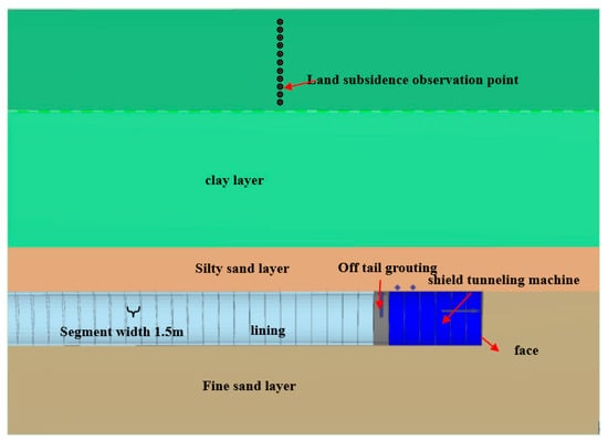
Figure 4.
Schematic diagram of tunnel excavation.
Table 3.
Modelling components’ parameters.
3.2. Shield Tunneling Process Simulation
In order to accurately model the tunnel excavation process, each part in the shield tunneling process is simulated, as shown in Figure 5, including the grouting body on the outside of the tube sheet, the conical shield tunneling machine, the grouting pressure at the end of the shield, and the pressure from the jack at the tunnel face.
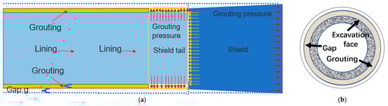
Figure 5.
Schematic diagram of shield tunnel machine construction: (a) longitudinal section and (b) cross-section.
For each component in the shield tunnelling process, the modeling approach is defined as follows:
(1) Grouting body: This is used to simulate a grouting layer filled between the excavation diameter and the outer diameter of the shield tube sheet. The strength is required to be similar to the original soil, and its width is related to the grouting fill ratio.
(2) The conical shield tunnel machine: The shield tunnel machine is modeled as a conical shape because the radius of the shield cutter excavation is larger than the outer diameter of the lining pipe sheet, leading to a conical tunnel, thereby allowing the mechanical excavation gap around the lining to be simulated. This simulation is realized by introducing an active strain to each unit in the shield tunnel machine, which decreases linearly with the length of the shield tunnel machine.
(3) The grouting pressure at the end of the shield: Because the synchronous grouting process is carried out when the shield tunnel machine leaves the shield tail, practical engineering proposes a general requirement for the grouting pressure. Meanwhile, the grouting pressure will impact the ground settlement. Therefore, this pressure is used to simulate the grouting process.
(4) The pressure from the jack: This pressure simulates the force applied to the lining by the jack during shield excavation. Specifically, this force is vertically distributed over the first row of lining segments at the tail.
(5) The pressure from the tunnel face: This aims to simulate the soil pressure during shield excavation. This pressure is mainly utilized to balance the external force applied by the water and soil outside the tunnel face. In the simulation, the pressure from the tunnel face increases vertically from the top to the bottom of the shield tunnel machine, and the pressure impacts the ground settlement. Here, the pressure at the tunnel face can be determined according to . Thus, the grouting pressure parameters during construction are defined as follows: n,ref = −350 kN/m2 and n,inc = −8 kN/m2. In addition, for the parameters for the tunnel–face pressure, n,ref = −235 kN/m2 and n,inc = −14 kN/m2. Moreover, for the parameters related to the jack force and tunnel face shrinkage, n = 550 kN/m2, ref = 0.7%, and inc, axial = −0.09333%/m. Furthermore, because the tunnel-face pressure and grouting pressure change with the soil depth, the tunnel vault is determined as the reference point, and the pressure increases linearly from this point. Likewise, the surface shrinkage is 0.0933%/m along the excavation surface, and the final shrinkage percentage is 0.7%.
(6) The simulated shield tunnel machine excavation process can be described as follows: ① after the establishment of the initial model and mesh generation, the initial effective stress, pore water pressure, and state parameters are determined; ② the plate support is adopted to simulate the shield tunnel machine between the 26.5 m and 35.5 m segments of the model (a total of 6 rings), the first 25 m of the model is used to simulate the excavated tunnel, and all water in the tunnel and shield tunnel machine is drained; ③ The stiffness migration method is utilized to simulate the shield machine, advancing one ring forward. The strata behind are supported by lining and grouting. No grouting body is set in the ring at the machine tail, but grouting pressure is applied to simulate the grouting process; and ④ following the same procedure, when the shield tunnel machine moves forward one ring, the process freezes the grouting pressure at the shield tail position from the previous step and fills the grouting body. This cycle repeats, eventually simulating the machine moving forward 26 rings.
(7) The determination of the gap parameters: Since the grouting at the shield tail will be carried out after the linear shrinkage of the machine, the width of the machine after the shrinkage is equal to the outer diameter of the grouting body, and the width of the tube sheet is unchanged. The width of the mechanical excavation gap Gp is the sum of the gap width of the linear shrinkage and the width of the grouting layer (i.e., the difference between the cutter diameter of the cutter plate excavation and the lining outer diameter), and it is known that Gp = 0.25 m. Then, considering the actual conditions, the grouting filling ratio is β = 81.94%, and the width of the grouting layer is set at 0.2049 m. Therefore, the gap between the grouting and soil layers is 0.045 m.
3.3. Simulation Results and Analysis
The calculation results of 26 rings of shield tunnel excavation were simulated and calculated. The contour plot of surface and longitudinal formation deformation is shown in Figure 6. At the same time, a comparative analysis diagram of the ground settlement curve from numerical simulation, improved theoretical calculations, and field measurements is presented in Figure 7.
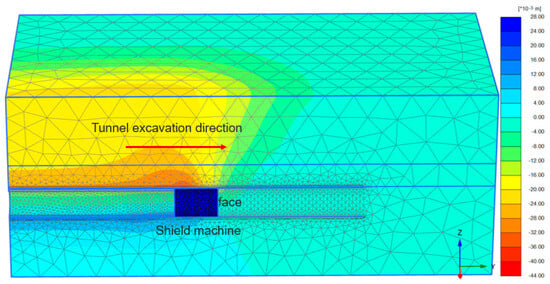
Figure 6.
Longitudinal settlement of the tunnel.
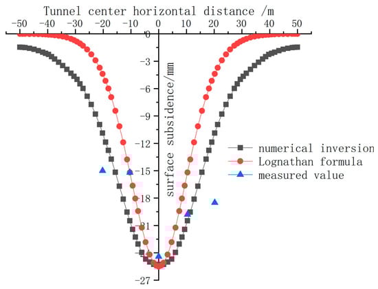
Figure 7.
Comparison of ground settlement curves.
As shown in Figure 6 and Figure 7, during the excavation, the longitudinal ground deformation gradually increases in the area where the shield machine approaches the shield tail, where the maximum longitudinal displacement is −38.44 mm and the maximum surface settlement . According to the gap parameter definition, the maximum longitudinal displacement approximately equals the gap parameter g. The ratio of to g is 0.66. According to Ng [24], who developed an empirical formula from 18 tunnel cases, the clay stratum in this tunnel area is characterized by soft consistency with low cohesion, while the tunnel bearing layer is a sandy layer, which is very consistent with the simulation results.
Based on the variation law of ground settlement, it can be seen that the settlement change aligns with the five deformation stages in shield tunnel construction [25,26]. Specifically, the largest settlement change occurs when the shield tail reaches the excavation section, and the shield machine passes through the observation section. These two stages are also called the construction stage of the shield machine. The primary reason for significant settlement is that the mechanical gap is incompletely filled with slurry during the grouting process at the shield tail, causing the stratum around the lining to invade the gap. After the concrete and the surrounding soil fill the gap, the stress released by the soil compresses the concrete grout, leading to the grout consolidating and compressing; this process further enlarges the gap and exacerbates deformation. These factors play the main role in ground settlement. Meanwhile, when the tunnel face support force is smaller than the groundwater and soil layer pressure, the former gap also influences settlement. According to the practical situation in this study, the influence of the formed gap on the settlement is slighter than other factors, which can be attributed to the fact that the support pressure is basically equal to external pressure in the numerical simulation, resulting in a small , and thus minimal impact on total settlement.
As shown in Figure 7, the comparative study, including analysis based on Loganathan’s theory and calculation results based on measured data, reveals minimal differences in maximum settlements among the three methods. The results from the theoretical formula and numerical simulation are both slightly smaller than the measured settlement, while the simulated settlement curve is more like the measured curve. This situation can be explained as follows: the Loganathan’s theory is conducted based on the uniform clay strata, and the impact of multiple strata on the tunnel excavation is ignored, while the numerical simulation focuses on different strata, including sand, clay, and others.
To summarize, when detailed construction process parameters are available, the introduction of gap parameter theory, modified by the grouting filling ratio, can better predict ground settlement. Additionally, for complex geological conditions, combined with three-dimensional numerical analysis, this approach can more accurately reflect the ground settlement characteristics in shield construction.
4. Sensitivity Analysis of Construction Process Parameters
Considering that construction technology significantly influences tunnel excavation, this section evaluates different parameters in the construction process to quantitatively analyze their influences on ground settlement. Because the adopted gap parameter theory considers the influence of grouting filling ratio β, three-dimensional elastic–plastic deformation parameter λ at the tunnel face, and the construction parameter n, six tunnel working conditions in different bearing layers are designed. Then, the simulated and analytical results are compared to obtain the construction parameters related to the strata conditions. After that, a sensitivity analysis is conducted to investigate the ground loss rate and tunnel face pressure ratio parameters. Finally, orthogonal tests are designed to analyze the influences of the construction factors on ground settlement, and the simulation results are validated against the theoretical predictions.
4.1. Ground Settlement Analysis Under Different Stratum Conditions
In this section, the strata of the Yangtze River section of Wuhan Metro Line 7 are used as the research object. The goal is to analyze the influences of tunnel bearing layers with different properties on ground settlement in binary structure strata. The actual stratum parameters in this area are used as the model parameters. The stratum stiffnesses, from large to small, are fine sand, silt sand, clay, and soft clay. Six models with different working conditions are established to analyze the influence of different geological conditions on the construction parameters. Based on the optimized gap parameter formula in this paper, the value range of the construction parameter n related to the stratum conditions is derived. As shown in Figure 8, the six working conditions are: (1) a clay layer as the bearing layer, with a fine sand layer at the bottom; (2) soft clay as the bearing layer, with fine sand at the bottom; (3) a binary structure: upper clay and bottom silty sand; (4) a binary structure: upper clay and bottom soft clay; (5) a binary structure: upper soft clay and bottom silty sand; and (6) a binary structure: upper soft clay and a bottom sand layer. The simulation results of the ground settlement for these six conditions are presented in Figure 9.
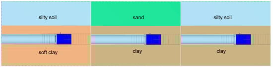
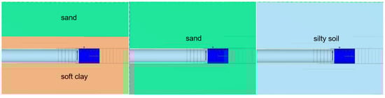
Figure 8.
Soil layer distribution with different bearing ability.
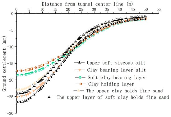
Figure 9.
Comparative analysis of surface settlement curves for different bearing soil layers.
From Figure 9, it can be found that: (1) the ground settlement of the clay layer as the bearing layer is smaller than that of the sand layer as the bearing layer; (2) the settlement of the soft clay layer is greater than that of the clay layer, and the settlement of the upper soft clay layer as the bearing layer is greater than that of the upper clay layer as the bearing layer; (3) the settlement of the silty sand layer as the bearing layer is greater than that of the fine sand layer; and (4) the settlement of the six conditions, in descending order, are: silty sand with the upper soft clay bearing layer, fine sand with the upper soft clay bearing layer, fine sand with the upper clay bearing layer, silty sand with the upper clay bearing layer, the soft clay bearing layer, and the clay bearing layer.
The simulation results indicate that: (1) the clay layer as a bearing layer is more stable than the sand layer; (2) worse stratum physical properties lead to greater ground settlement; and (3) the bearing layer properties have a greater influence on ground settlement than those of the upper layer.
By combining the proposed theoretical formula for the optimized gap parameter with the abovementioned content and considering the influence of the upper stratum and bearing layer properties on ground settlement, with the bearing layer exerting a greater influence, the parameters for the bearing layer are selected from the stratum parameters while keeping construction parameters consistent. The ground settlement curves of the six conditions are shown in Figure 10.
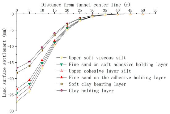
Figure 10.
The surface settlement curves of the different bearing soil layers based on the optimized gap parameter theory.
As shown in Figure 10, the ground settlement curves derived from the optimized gap parameter theoretical formula show good consistency with the settlement data and numerical simulation curve shapes. Thus, the optimized gap parameter theoretical formula can be used to predict and analyze multi-stratum conditions, such as binary structure strata.
By comparing simulation data, the construction parameter n in the optimized gap parameter formula ranges from 1.0 to 1.5. For binary structure strata: (1) when sand serves as the bearing layer, n is 1.0–1.2; (2) when silty sand serves as the bearing layer in the binary structure, n is 1.0–1.1; (3) when fine sand serves as the bearing layer, n is 1.1–1.2; and (4) when clay serves as the bearing layer, n is 1.3–1.5. The worse the stratum stability, the smaller the n value.
4.2. Gap Parameter Analysis Under the Different Grouting Filling Rates
Assuming that the influence of gap parameters, including grouting pressure and tunnel face pressure, is not considered, the gap caused by the abovementioned tunnel construction is very small and negligible. Then, the simulated mechanical excavation gap parameter (the gap parameter between the outer diameter of the tube sheet and the outer diameter of the excavation surface) is = 0.25 m. Under this condition, i = 0, and the corresponding grouting gap parameter can be calculated according to Equation (14), g1 = (1 − β). Thus, when the grouting fill rate is determined from 60 to 100%, with an interval of 10%, they are 0 m, 0.025 m, 0.05 m, 0.075 m, and 0.1 m, respectively. Here, the involved model parameters can be summarized as follows: the grouting pressures are n,ref = −320 kN/m2 and n,inc = −21 kN/m2; the tunnel face pressures are n,ref = −235 kN/m2 and n,inc = −14 kN/m2; the jack thrust is n = 550 kN/m2; and the shrinkage percentage is ref = 0%. It is assumed that the slurry filling the mechanical excavation gap is considered the soil in the corresponding area and is uniformly distributed around the lining. Then, the gap is simulated based on the face shrinkage function, namely, it is assumed that the slurry filling the mechanical excavation gap has shrunk the tunnel by per meter along the unit diameter, and the corresponding parameters for the face shrinkage ref = , in which , which represent the excavation diameter ref, are 0%, 0.39%, 0.78%, 1.16%, and 1.55%, respectively. The corresponding ground settlement curves are calculated and shown in Figure 11.
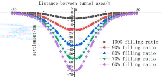
Figure 11.
Simulated transverse surface settlement curves under the different grouting filling ratios.
As shown in Figure 11, with every 10% increase in the grouting filling ratio, the maximum ground settlement increases by more than 15 mm. Meanwhile, when the grouting filling ratio reaches 60% and the maximum ground settlement is about 70 mm, which means that the grouting filling rate has a significant impact on the ground settlement.
4.3. Simulation and Analysis of the Gap Parameters Under the Different Support Pressure Ratios
Assuming that the grouting completely fills the gap, the support pressure ratios are analyzed based on five values: 0.6, 0.7, 0.8, 0.9, and 1.0. The pressure at the tunnel face of the model is used to simulate the tunnel face soil pressure to balance the stratum soil pressure and the pore water pressure during excavation. If the applied pressure at the tunnel face is greater than the external force, the soil layer moves toward the excavation face, otherwise, the soil will move in the opposite direction. When the simulated pressure at the tunnel face achieves a balanced state, namely, the support pressure ratio is 1.0, the involved model parameters are shown as follows: the grouting pressure is n,ref = −320 kN/m2, n,inc = −21 kN/m2; the tunnel face pressures are n,ref = −235 kN/m2 and n,inc = −14 kN/m2; the jack thrust is n = 550 kN/m2; and the shrinkage percentages are ref = 0% and inc,axial = 0%/m. The analytical results of the model are shown in Figure 12.
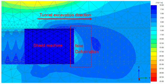
Figure 12.
Incremental displacement in the Y direction at the tunnel face.
As shown in Figure 12, the stratum deformation direction at the tunnel face moves toward the excavation direction, and the maximum displacement is about 5 mm. This value can be ignored, compared to the overall displacement of tunnel excavation. Therefore, it can be considered that the force at the tunnel face is in a balanced state. Under the condition of balanced pressure, n,ref = −235 kN/m2 and n,inc = −14 kN/m2, the support pressure ratio is determined as 0.9, 0.8, 0.7, and 0.6, respectively. The values of corresponding support pressures are −211 kN/m2, −188 kN/m2, −165 kN/m2, and −150 kN/m2, respectively. The corresponding ground settlements are shown in Figure 13.
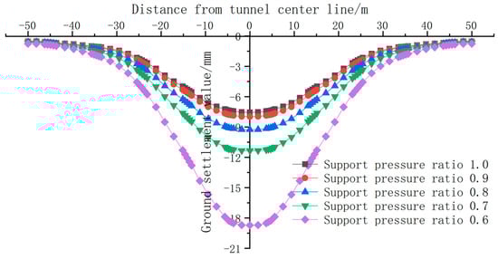
Figure 13.
Simulated transverse surface settlement curves under different support pressure ratios.
Based on Figure 12 and Figure 13, it can be seen that the support pressure ratio has a smaller effect on the ground settlement than the grouting filling ratio. The maximum ground settlement when the support pressure ratio is between 1.0 and 0.7 is within 10 mm. However, the ground settlement increases dramatically when the support pressure ratio is 0.6. The reason may be explained as follows: the deformation at the tunnel face under this support pressure ratio is large, which exceeds the bearing capacity of the soil storage space at the tunnel face, resulting in a large amount of water and soil outside the tunnel face pouring into the soil bin storage space. Therefore, in actual shield construction, the support pressure ratio should be kept above 0.7 as much as possible, otherwise it is easy to cause safety accidents.
4.4. Sensitivity Analysis of Ground Settlement to Construction Process Based on Orthogonal Experiment
In order to quantitatively analyze the influence of the three factors on ground settlement, including the grouting filling ratio, support pressure ratio, and construction parameter n, three levels for each factor are adopted. According to previous engineering experience, the grouting filling ratio is generally from 60% to 90%, the support pressure ratio generally ranges from 0.0 to 1.0, and the construction parameter is determined based on the previous section. Therefore, to consider the range of each factor and to ensure the same change ratio at each level, the level values of the three factors are as follows: (1) the grouting filling ratio: 70%, 80%, and 90%; (2) the support pressure ratio: 0.8, 0.9, and 1; and (3) construction parameter n: 1.0 (soft clay bearing layer silty sand), 1.2 (clay bearing layer fine sand), and 1.4 (clay bearing layer).
The orthogonal experimental design method was used to design nine groups of orthogonal experimental schemes with three factors and three levels. The maximum ground settlement values for the nine pairing methods were then calculated using the numerical simulation method [27]. The pairing methods and results are shown in Table 4.
Table 4.
Construction technology factors.
As shown in Table 5, the maximum deviations in the grouting filling ratio, the support pressure ratio, and the stratum conditions are 14.6, 5.6, and 5.1, respectively. Therefore, the influence of the grouting filling rate on ground settlement is greater than that of the support pressure ratio, and the stratum conditions have the least influence on ground settlement, which confirms the conclusions from Section 4.1 and Section 4.2. The greatest influence on ground settlement is the grouting filling ratio of 70%, the support pressure ratio of 0.6, and the stratum conditions of soft clay in the upper part and silty sand in the lower bearing layer. The combination with the smallest influence on ground settlement is the grouting filling ratio of 90%, the support pressure ratio of 1.0, and the clay stratum as the bearing layer.
Table 5.
Deviation analysis of construction technology factors.
From Table 6, it can be seen that the orthogonal test is the L9 (33) type. According to the critical F-value table (F0.01 = 99.166 and F0.05 = 19.164), the F-value for the grouting filling ratio is 175.87, which is greater than F0.01, while the F-value for the support pressure ratio and stratum conditions falls between F0.01 and F0.05. Therefore, the influence of the grouting filling ratio on ground settlement is highly significant, whereas the influence of the support pressure ratio and stratum conditions on ground settlement is relatively significant. According to the proposed modified formula in this study, the deviation analysis of the orthogonal test is shown in Table 7.
Table 6.
Variance analysis on numerical simulation of construction technology factors.
Table 7.
Deviation analysis of theoretical calculation of construction technology factors.
The comparison between Table 5 and Table 7 reveals that the largest deviation between the two methods still lies in the influence of the grouting filling rate on ground settlement, followed by the stratum conditions and the support pressure ratio, with the worst scenario being a 70% grouting filling rate, 0.6 support pressure ratio, and stratum conditions with upper soft clay and a lower silty bearing layer. The difference between the two methods is that the deviation in the grouting filling ratio calculated by the theoretical formula accounts for a relatively small proportion, while the stratum conditions account for a relatively large proportion. In summary, the optimized gap parameter theoretical formula can predict complex stratum environments, such as binary structure strata, with results that are relatively accurate, and the details that meet the requirements for practical engineering applications.
5. Conclusions
In this paper, to control shield tunnel construction-induced ground settlement, an optimized gap parameter theory has been proposed to consider the influence brought by construction technology factors, and then the proposed optimized gap parameter theory is combined with a 3D finite element analysis method to analyze ground settlement in practical tunnel excavation engineering. To verify the superiority, one section of Wuhan Metro Line 7 was selected to validate the proposed method, and the existing methods were also adopted to conduct a comparative study. Some conclusions can be drawn, as follows:
(1) The existing gap parameter theory proposed by Rowe and Lee [10] was optimized by considering the influence of the grouting filling rate, then, based on the practical engineering of Wuhan Metro Line 7, the calculated gap parameter was input into the Loganathan formula to analyze the influence of tunnel construction technology on ground settlement. Compared to the measured data and results calculated by the Peak formula, the proposed method effectively captures ground settlement patterns.
(2) Based on the tunnel excavation of Wuhan Metro Line 7, the proposed gap parameter theory was used to establish a 3D finite element model to analyze the influence of the construction parameters on ground settlement during shield tunneling. The obtained results are consistent with the existing literature, which identifies five settlement stages. The ratio of the obtained maximum ground settlement to the maximum stratum settlement (i.e., gap parameter) is 0.7. Based on the previous research, it can be explained as follows: in the simulation, the stratum conditions in the tunnel are relatively soft, and the sand layer under the tunnel also causes the ratio to be too large.
(3) Six different bearing stratum working condition models were established, compared, and analyzed with the theoretical formula to obtain the value range of the construction parameter n in the correction gap parameter formula. The value range is between 1 and 1.5. This parameter value is related to the nature of the stratum conditions. The worse the stratum environment, the smaller the value of n. The numerical simulation calculation results indicate that under the binary stratum structure, the order of the influence of stratum conditions on ground subsidence, from greatest to least, is as follows: if the upper stratum is soft clay, the bearing layer is a silt layer; if the upper stratum is clay, the bearing layer is a silt layer; if the upper stratum is soft clay, the bearing layer is a fine sand layer; if the upper stratum is clay, the bearing layer is a fine sand layer; and if the bearing layer is soft clay, the bearing layer is a clay layer.
(4) Based on the orthogonal tests and 3D finite element simulation, the sensitivity analyses of the grouting filling ratio, support pressure ratio, and stratum conditions were conducted. The results show that the grouting filling rate has the most obvious impact on ground settlement, while the support pressure ratio and stratum conditions also have a certain impact on ground settlement. In the deviation analysis between the optimized gap parameter theory and numerical simulations, there is no significant difference between the two methods, however, for the theoretical formula, the influence of stratum conditions on ground settlement accounts for a relatively large proportion, which means that the optimized gap parameter theory can predict more complex stratum conditions, such as binary structure strata, and the prediction results should be further improved with better accuracy.
Author Contributions
Conceptualization, H.G. and G.Z.; methodology, H.G.; writing—original draft preparation, H.G. and G.Z.; writing—review and editing, Z.W. and J.W. All authors have read and agreed to the published version of the manuscript.
Funding
This research received no external funding.
Data Availability Statement
The original contributions presented in the study are included in the article, and further inquiries can be directed to the corresponding author.
Conflicts of Interest
The authors declare that this research was conducted in the absence of any commercial or financial relationships that could be construed as potential conflicts of interest.
References
- Chen, Y.H.; Pan, H.H. A case study of urban road subsidence induced by the underground connection of the shield tunnelling method. IOP Conf. Ser. Mater. Sci. Eng. 2019, 615, 012025. [Google Scholar] [CrossRef]
- Liu, X.Q.; Yang, Y.H.; Pei, W.B. Analysis on influence of metro shield on ground subsidence. IOP Conf. Ser. Mater. Sci. Eng. 2017, 248, 012032. [Google Scholar] [CrossRef]
- Peck, B.B. Deep excavations and tunneling in soft ground. In Proceedings of the 7th International Conference on Soil Mechanics and Foundation Engineering, Mexico City, Mexico, 1969; pp. 225–290. [Google Scholar]
- Ağbay, E.; Topal, T. Evaluation of twin tunnel-induced surface ground deformation by empirical and numerical analyses (NATM part of Eurasia tunnel, Turkey). Comput. Geotech. 2020, 119, 103367. [Google Scholar] [CrossRef]
- Lou, P.; Li, Y.; Tang, X.; Lu, S.; Xiao, H.; Zhang, Z. Influence of double-line large-slope shield tunneling on settlement of ground surface and mechanical properties of surrounding rock and segment. Alex. Eng. J. 2023, 63, 645–659. [Google Scholar] [CrossRef]
- Han, L.; Ye, G.L.; Chen, J.J.; Xia, X.H.; Wang, J.H. Pressures on the lining of a large shield tunnel with a small overburden: A case study. Tunn. Undergr. Space Technol. 2017, 64, 1–9. [Google Scholar] [CrossRef]
- Chakeri, H.; Ozcelik, Y.; Unver, B. Effects of important factors on surface settlement prediction for metro tunnel excavated by EPB. Tunn. Undergr. Space Technol. 2013, 36, 14–23. [Google Scholar] [CrossRef]
- Hu, X.; He, C.; Lai, X.; Walton, G.; Fu, W.; Fang, Y. A DEM-based study of the disturbance in dry sandy ground caused by EPB shield tunneling. Tunn. Undergr. Space Technol. 2020, 101, 103410. [Google Scholar] [CrossRef]
- Lan, X.; Zhang, X.; Li, X.; Li, Z.; Liu, Y.; Xia, M. Model experiment on surface subsidence induced by excavation of shallow small-spacing tunnels. Environ. Earth Sci. 2022, 81, 133. [Google Scholar] [CrossRef]
- Kim, S.H.; Burd, H.J.; Milligan, G.W.E. Model testing of closely spaced tunnels in clay. Géotechnique 1998, 48, 375–388. [Google Scholar] [CrossRef]
- Yan, B.; Wang, R.; Wang, Y. Deformation of adjacent buildings and ground settlement induced by shield construction of three-line small-spacing tunnels. Alex. Eng. J. 2023, 79, 237–251. [Google Scholar] [CrossRef]
- Rowe, R.K.; Lee, K.M. Subsidence owing to tunnelling. II. Evaluation of a prediction technique. Can. Geotech. J. 1992, 29, 941–954. [Google Scholar] [CrossRef]
- Zhang, P.; Pan, Y.; Yu, Z.; Guan, X.; Wang, G.; An, J.; Lei, H. Ground subsidence characteristics caused by construction of shallow-buried tunnel in a sandy soil composite formation. Arab. J. Geosci. 2020, 13, 901. [Google Scholar] [CrossRef]
- Guo, H.Z. Impact of Shield Tunnel Construction on Ground Settlement and Building Deformation of Wuhan Metro Line 7; Wuhan Institute of Technology: Wuhan, China, 2017. [Google Scholar] [CrossRef]
- Attewell, P.B.; Yeates, J.; Selby, A.R. Soil Movement Induced by Tunnelling and Their Effects on Pipelines and Structures; Blackie: Glasgow, Scotland, 1986; pp. 10–50. [Google Scholar]
- Jiang, X.L.; Zhao, Z.M.; Li, Y. Analysis and calculation of surface and subsurface settlement through profiles due to tunneling. Rock Soil Mech. 2004, 25, 1542–1544. [Google Scholar]
- Cording, E.J.; Hansmire, W.H. Tunnels in soils-general report. In Proceedings of the 5th Pan American Conference of Soil Mechanics and Foundation Engineering, Bueno Aires, Argentina, October 1975; p. 63. [Google Scholar]
- Zhu, C.H.; Li, N.; Liu, H.X.; Zhang, Z.Q. Analysis on the law of surface settlement induced by shield construction technology. Rock Soil Mech. 2011, 32, 158–164. (In Chinese) [Google Scholar]
- Zhang, Y.; Yin, Z.Z. Analysis of surface deformation caused by shield tunneling. Chin. J. Rock Mech. Eng. 2002, 21, 388–392. [Google Scholar]
- Rowe, R.K.; Lo, K.Y.; Kack, G.J. A method of estimating surface settlements above tunnels constructed in soft ground. Can. Geotech. J. 1983, 20, 11–22. [Google Scholar] [CrossRef]
- Loganathan, N.; Poulos, H.G. Analytical prediction for tunneling-induced ground movements in clays. J. Geotech. Geoenvironmental Eng. 1998, 124, 846–856. [Google Scholar] [CrossRef]
- Han, X. Research on Practical Methods for Predicting Strata Displacement and Building Deformation Caused by Tunnel Construction; Xi’an University of Technology: Xi’an, China, 2006. [Google Scholar]
- Lu, C.; Luo, L.; Wang, X.; Du, X.L. Soft/hard constitutive model and numerical realization of soil contact surface. Eng. Mech. 2017, 34, 41–50. [Google Scholar]
- Ng, R.M.C. A procedure for prediction of settlement due to tunnels in clays. In Proceedings of the Pan American Conference Soil Mechanics and Foundations Engineering, Vina del Mar, Chile, 26–30 August 1991; Volume 3, pp. 1413–1430. [Google Scholar]
- Liu, J.H.; Hou, X.Y. Shield Tunneling; China Railway Publishing House: Beijing, China, 1991. [Google Scholar]
- Ai, Q.; Yuan, Y.; Mahadevan, S.; Jiang, X. Maintenance strategies optimization of metro tunnels in soft soil. Struct. Infrastruct. Eng. 2017, 13, 1093–1103. [Google Scholar] [CrossRef]
- Fang, K.T.; Ma, C.X. Orthogonal and Uniform Experimental Design; Science Press: Beijing, China, 2001. [Google Scholar]
Disclaimer/Publisher’s Note: The statements, opinions and data contained in all publications are solely those of the individual author(s) and contributor(s) and not of MDPI and/or the editor(s). MDPI and/or the editor(s) disclaim responsibility for any injury to people or property resulting from any ideas, methods, instructions or products referred to in the content. |
© 2025 by the authors. Licensee MDPI, Basel, Switzerland. This article is an open access article distributed under the terms and conditions of the Creative Commons Attribution (CC BY) license (https://creativecommons.org/licenses/by/4.0/).