Article

Constrained Optimization for the Buckle and Anchor Cable Forces Under One-Time Tension in Long Span Arch Bridge Construction

by
Xiaoyu Zhang
1,
Xuming Ma
2,
Wei Chen
2,
Wei Xu
1,
Yuan Kang
3 and
Yonghong Wu
1,*
1
Faculty of Civil Engineering and Mechanics, Kunming University of Science and Technology, Kunming 650500, China
2
China Railway Bridge Science Research, Ltd., Wuhan 430034, China
3
POWERCHINA SINOHYDRO ENGINEERING BUREAU 14 CO., LTD., Kunming 650500, China
*
Author to whom correspondence should be addressed.
Buildings 2025, 15(9), 1529; https://doi.org/10.3390/buildings15091529
Submission received: 2 April 2025 / Revised: 23 April 2025 / Accepted: 28 April 2025 / Published: 2 May 2025
(This article belongs to the Section Building Structures)

Abstract

During long-span arch bridge construction, repeated adjustments of large cantilevered segments and nonuniform cable tensions can lead to deviations from the desired arch profile, reducing structural efficiency and increasing labor and material costs. To precisely control the process of cable-stayed buckle construction in long-span arch bridges and achieve an optimal arch formation state, a constrained optimization for the buckle and anchor cable forces under one-time tension is developed in this paper. First, by considering the coupling effect of the cable-stayed buckle system with the buckle tower and arch rib structure, the control equations between the node displacement and cable force after tensioning are derived based on the influence matrix method. Then, taking the cable force size, arch rib closure joint alignment, upstream and downstream side arch rib alignment deviation, tower deviation, and the arch formation alignment displacement after loosening the cable as the constraint conditions, the residual sum of squares between the arch rib alignment and the target alignment during the construction stage is regarded as the optimization objective function, to solve the cable force of the buckle and anchor cables that satisfy the requirements of the expected alignment. Applied to a 310 m asymmetric steel truss arch bridge, the calculation of arch formation alignment is consistent with the ideal arch alignment, with the largest vertical displacement difference below 5 mm; the maximum error between the measured and theoretical cable forces during construction is 4.81%, the maximum difference between the measured and theoretical arch rib alignments after tensioning is 3.4 cm, and the maximum axial deviation of the arch rib is 5 cm. The results showed the following: the proposed optimization method can effectively control fluctuations of arch rib alignment, tower deviation, and cable force during construction to maintain the optimal arch shape and calculate the buckle and anchor cable forces at the same time, avoiding iterative calculations and simplifying the analysis process.

1. Introduction

Arch bridges are widely used due to their structural stability and load-bearing capacity [1,2]. Several world-class long-span arch bridges have been built, such as Deyu Bridge, Chenab Bridge, and Fenglai Bridge [3,4,5]; these bridges further illustrate the global significance and wide-ranging application of arch bridge technology.
Among various construction techniques, the cable-stayed buckle method has gained prominence in arch bridge engineering owing to its minimal site occupancy and millimeter-level installation precision; the precise determination of the buckle and anchor cable forces constitutes the fundamental theoretical basis for achieving effective construction control, ensuring both structural stability and alignment accuracy during the arch formation process.
When constructing large-span arch bridges using the cable-stayed buckle method, the strategies for calculating the cable forces of the buckle and anchor can be divided into two categories: result optimization with a controllable process and process optimization with a controllable result. The former takes the ideal arch alignment and stress under a one-time arching condition as the optimization objective and finds the optimal solution for a specific buckle cable force by manual or computer optimization algorithms within a certain feasible region. The latter takes the minimum deviation of the arch rib alignment from the target shape during construction as the optimization objective and solves the once-tensioned buckle cable force that meets the requirements, using the deviation of the arch formation alignment and the stress limit of the arch rib as the constraints.
The core idea of result optimization with a controllable process is to ensure that the arch’s alignment and stress state closely adhere to design requirements or an ideal state through precise calculations and control measures, while keeping key construction parameters, such as arch rib alignment and stress, within acceptable limits. Initially, the performance maintenance of the arch bridge during long-term service is considered, to reduce the negative influence of the cumulative initial stresses and initial deflection of the steel pipe on the bearing capacity of the arch bridge [6]. To achieve an optimal arch formation state, several studies have aimed at ensuring that the cumulative alignment and stresses of the arch ribs after construction align with those achieved under a single arching condition, using this consistency as the ultimate control objective and evaluation criterion. Classical calculation methods, such as the zero displacement method [7], the iterative method [8,9], and the influence matrix method [10], are widely used for determining the buckle and anchor cable forces of arch bridges during the construction of cable-stayed buckling. However, the single calculation methods have some limitations. Specifically, the iterative process of the zero displacement method is cumbersome and may lead to negative buckle forces [11]. The influence matrix method is usually applied to specific loading conditions and structural forms, and recalculation of the impact matrix may take more time and affect efficiency if the loading conditions change frequently [12]. Therefore, the combinations of various calculation methods have been widely used to reduce computational complexity and improve the accuracy of the results. For example, Yu Yujie et al. [12] first proposed the improved zero displacement method, which can quickly obtain the buckle force to meet the requirements of the arch alignment; then, the stress-free state control method was used to inversely derive the buckling force in each stage of construction. Li et al. [13] combined the influence matrix with linear programming using the golden section and iterative forward methods to determine appropriate cable forces by considering tangential displacement effects. The “Quiet do not move” method [14,15] posits that tensioning the buckle and anchor cables in a new arch rib section does not disturb the linearity of the preceding section; it uses a zero vertical displacement at the front end of the previous arch rib as the target for cable force calculation. In contrast to methods that control cable force by maintaining the arch line, Liu et al. [16] derived a stress balance equation—considering solely tensile stress—to compute feasible initial cable forces based on the allowable tensile stresses in the arch ribs. Additionally, Tian Zhongchu et al. [17] employed a concrete arch rib stress balance equation along with an influence matrix to define a series of cable forces according to the allowable stresses at the arch’s critical sections.
With the increasing span of arch bridges [18,19], it is usually difficult to accurately adjust and control the arch rib alignment and stresses during construction using the result optimization with a controllable process method; therefore methods of process optimization with a controllable outcome have been introduced. The core concept of the process optimization with a controllable outcome involves the use of the buckle cable force as an optimization variable and the determination of its optimal value by defining objective functions and constraints. Zhang Zhicheng et al. [20] first applied optimization theory to calculate the buckle cable force; the minimization of the sum of the squared linear deviations of the arch formation alignment from the design expectation was the optimization objective, and the internal force and displacement deviation during the construction were regarded as the variables for solving the buckle cable force. Zhang et al. [21] calculated the buckle cable force and the arch rib installation alignment by considering the arch rib alignment, stress during construction, and arch formation alignment as optimization objectives during construction. Zhou Qian et al. [22] developed an ANSYS-based cable force calculation program that incorporates automatic parameter adjustments during iterations and accounts for temperature effects. Qin Dayan et al. [23] utilized the deviation between the final and target line shapes after cable loosening as a constraint, aiming to minimize the discrepancy between the installation and target line shapes during construction as the optimization objective, thereby determining the optimal primary tensioning cable force. Zhou Yin et al. [24] developed an optimization model that integrates constraints such as tower deviation, the arch rib sealing hinge state, the arch rib closing state, and the arch formation alignment deviation to determine the optimal primary tensioning force for the buckle cable. In a similar vein, Song et al. [25] introduced a differential evolution method that merges an alternative model with a B-spline interpolation curve to optimize the cable force in cable-stayed bridges. Meanwhile, Hatsu Tanaka et al. [26] applied an enhanced version of the non-dominated sorting genetic algorithm II (NSGA-II) to optimize cable forces under multiple objectives, thereby addressing issues of computational inefficiency and insufficient consideration of the arch bridge stress state present in existing methods.
Unfortunately, it is difficult for both schemes to comprehensively consider tower deviation, arch rib alignment, and cable force uniformity throughout the construction process. Meanwhile, to control the line shape, frequent adjustments of the buckle and anchor cable forces are required, resulting in inefficient construction. Additionally, there is a lack of equations for the cable forces and displacements before and after the system transformation, causing the final arch to deviate from the target shape. Recognizing these critical limitations and research gaps, this study proposes a novel constrained optimization method for determining buckle and anchor cable forces under one-time tension during cable-stayed buckle construction. Unlike prior methods, the proposed approach systematically unifies three critical control objectives: tower deviation mitigation, arch rib alignment precision, and cable force uniformity within a single optimization framework. Additionally, this study develops comprehensive equations explicitly relating control node displacements and cable forces, both pre- and post-system transformation, addressing existing methodological shortcomings.
Considering the above issues, a constrained optimization for the buckle and anchor cable forces under one-time tension during the process of cable-stayed buckle construction is proposed; its applicability and effectiveness are validated through application to the construction control of a 310 m asymmetric steel truss arch bridge. The paper is structured as follows: Section 2 details the extraction of the influence matrix, the derivation of the relation equation between the control node displacements and the cable forces, and the formulation of the full-process constrained optimization model. Section 3 applies the proposed method to analyze both the cable force and the alignment of the aforementioned arch bridge, thereby assessing construction accuracy and verifying the method’s performance. The final section summarizes the main conclusions of the study.
The research aim of this study is to develop and validate a comprehensive constrained optimization framework for determining buckle and anchor cable forces in the cable-stayed buckle construction of large-span arch bridges. The influence matrix method operates under four fundamental assumptions to ensure validity [27,28,29]: (1) linear elastic material behavior, (2) small displacement theory, (3) invariant boundary conditions, and (4) applicability of the principle.

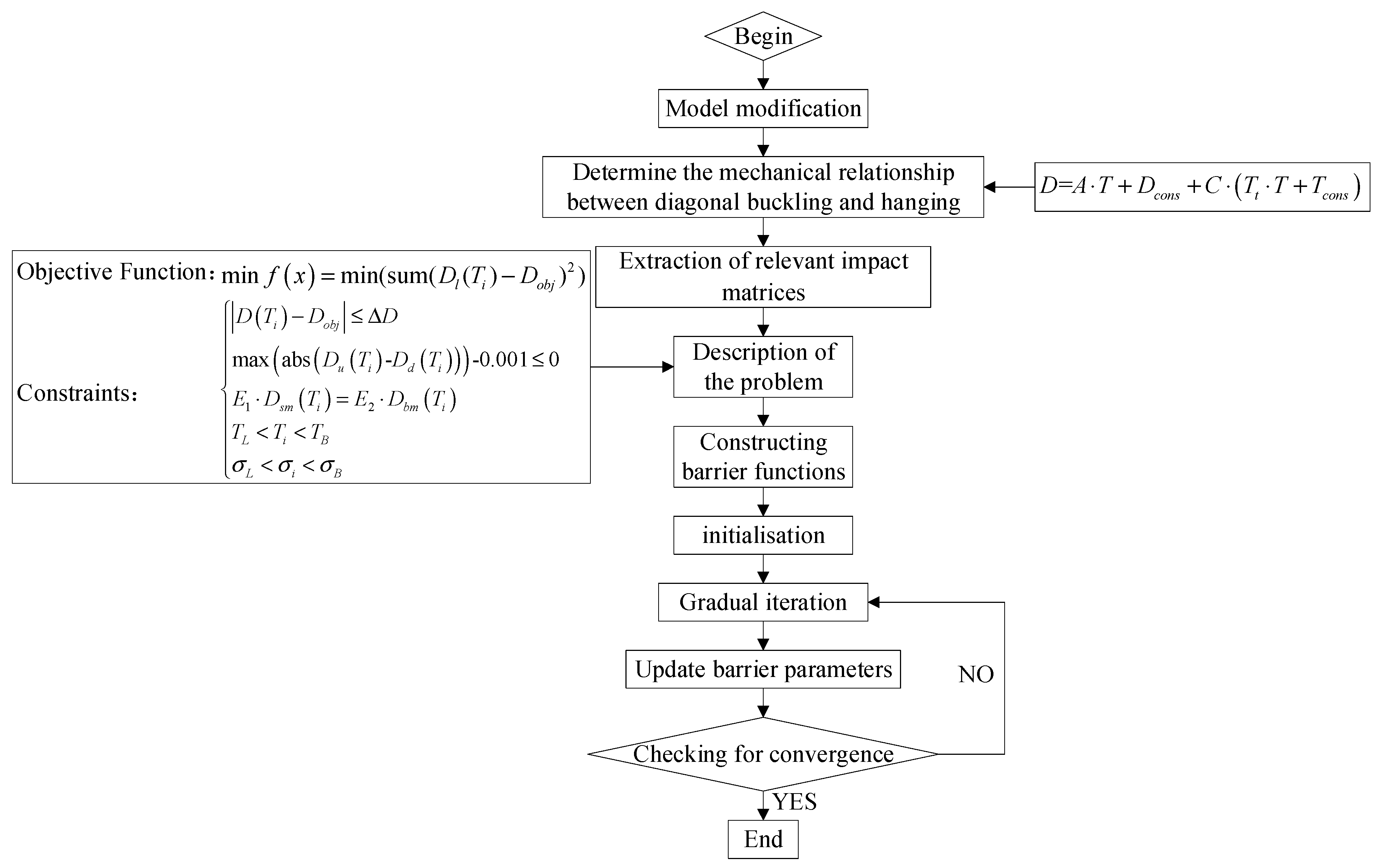
2. Full-Process Constrained Optimization Method

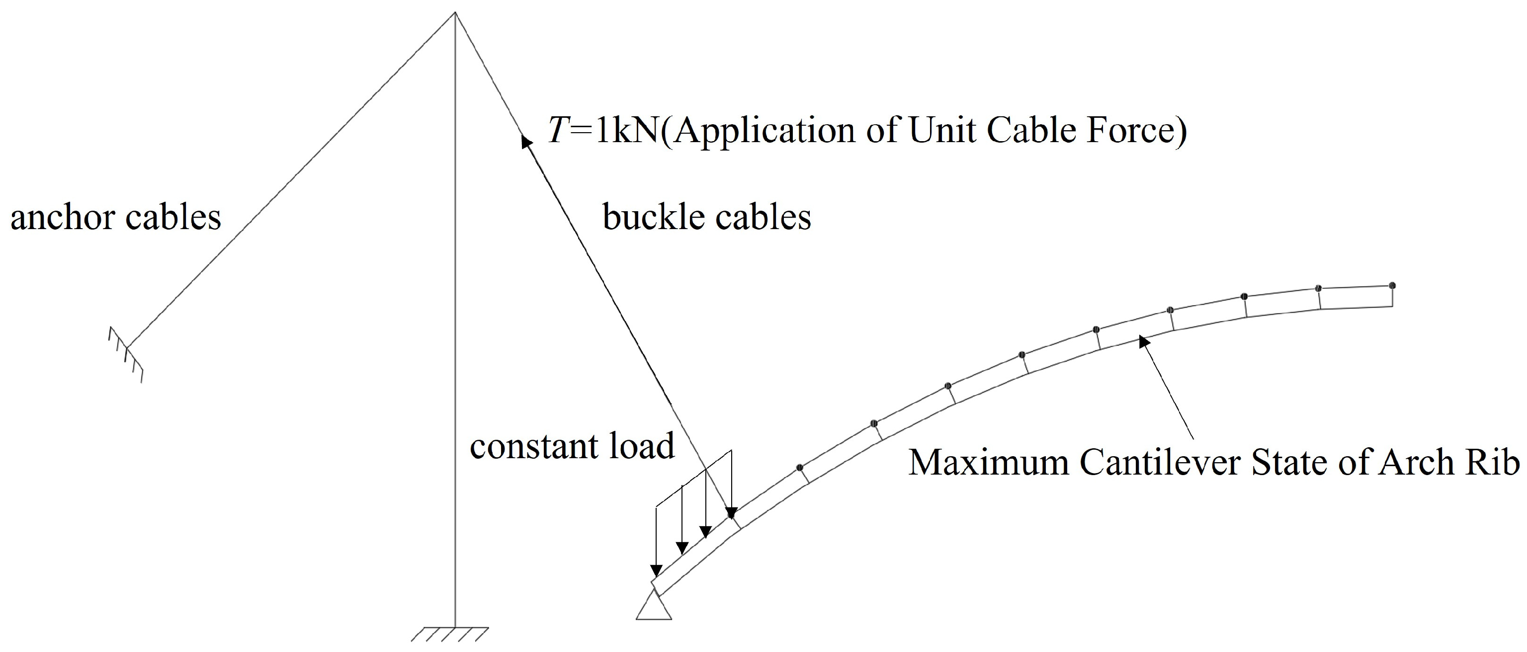
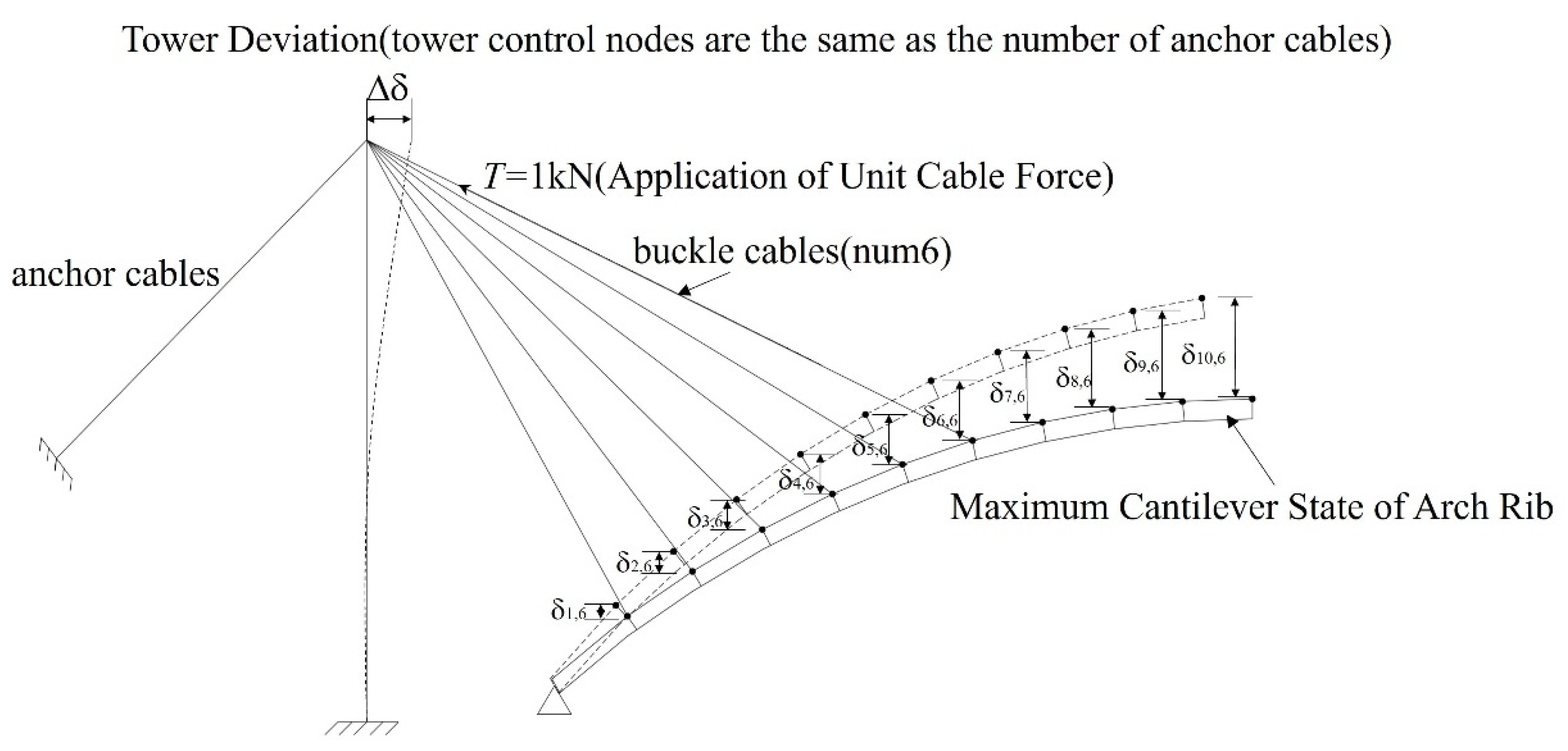
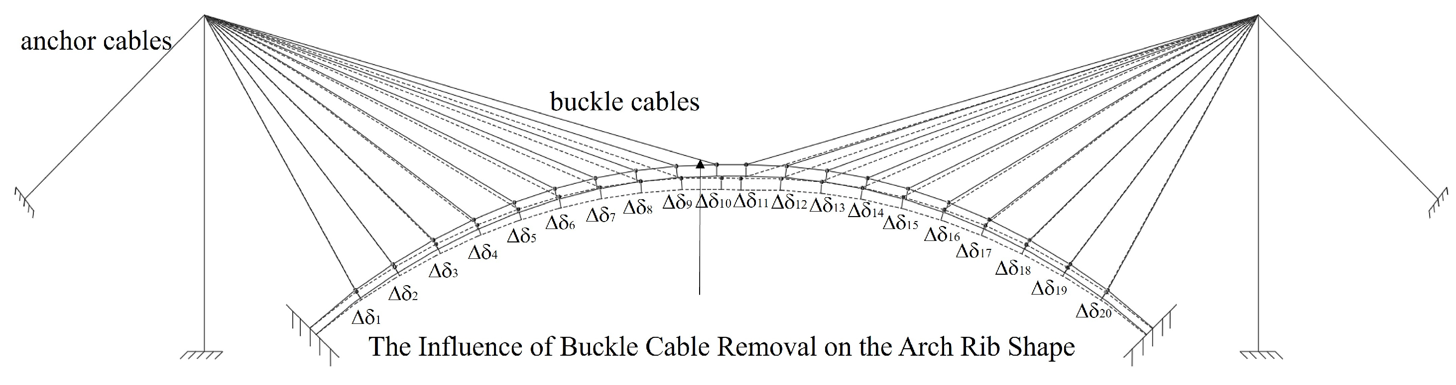
2.1. Initial Cable Force Calculation

For cantilever construction bridges, the newly constructed segments are influenced by the already built segments. To accurately simulate the consideration of the coupling effect of the cable-stayed buckle system with the buckle tower and arch rib structure and to ensure the reliability of the extracted influence matrix in the construction stage model, the model can activate the maximum cantilever unit at the same time. Subsequently, the weight, load, and corresponding boundary conditions are activated sequentially according to the construction sequence to ensure the tangent assembly relationship between the newly installed and existing arch rib segments. The model modification process is shown in Figure 1.
The initial cable forces of the buckle and anchor cables are regarded as the unknown variables, while the arch rib displacement and buckle tower deviation are considered as the target functions. Assuming n backstays and m control nodes on the arch rib and tower, the unknown variable vector is denoted as T = (T1, T2, ⋯, Tn)T, and the target displacement vector is D = (Δ1, Δ2, …, Δm)T; the displacement vector under constant loads (arch rib, wind braces, and cable loads) is Dcons = (d1, d2, …, dm)T. When an element in the active variable vector T changes due to a unit cable force, the corresponding displacement of the control variable vector is subsequently changed, which can be expressed as Equation (1), and Figure 2 illustrates how tensioning a cable affects the displacement of control nodes during the construction process.
A = δ 1 , 1 δ 1 , n δ m , 1 δ m , n
The equation AT + Dcons = D was commonly used to calculate cable forces during the process of cable-stayed buckle construction. As the cable-stayed buckle system is a temporary structure, the tensioning and removal of buckle and anchor cables can significantly affect the arch rib alignment. Failure to adequately account for changes in the arch rib system could result in obvious deviations between the arch formation alignment and the intended design after cable release. When tension is applied to the cables in the construction sequence, the forces in the already activated cables will vary accordingly; Figure 3 demonstrates the influence of tension cable force on the cable force of other cables. The influence of cable tensioning on the force matrix is expressed as T t = T 1 , T 2 , , T t , , T n T , while the influence vector under constant loads (self-weight of the arch rib, wind braces, and cables) is represented as Tcons = (f1, f2, , fn)T; the influence of T t is shown in Equations (2) and (3):
T 1 = T 1 + Δ T 1 , 2 + Δ T 1 , 3 + Δ T 1 , n T 2 = T 2 + Δ T 2 , 3 + Δ T 2 , 4 + Δ T 2 , n T t = T t + Δ T t , t + 1 + Δ T t , t + 2 + Δ T t , n
T t = T t + Δ T t , t + 1 + Δ T t , t + 2 + Δ T t , n t = 1 , 2 n 1
where T t represents the tension in the t-th cable prior to arch rib closure and the release of the buckle and anchor cables. Tt denotes the initial tension in the t-th cable. Δ T t ,   n   ( t = 1 ,   2 ,   ,   n 1 ) indicates the change in tension of the corresponding cable after the n-th cable has been tensioned.
The effect of removing the buckle and anchor cables on the displacement of the arch rib after its closure is represented by Equation (4). Figure 4 illustrates how the arch rib displacement is impacted when the cable is removed.
C = ε 1 , 1 ε 1 , n ε m , 1 ε m , n
Based on the superposition principle, the interaction mechanism between cable tension forces and control point displacements undergoes two distinct operational stages. As established in prior research, the entire process comprises an active tensioning stage followed by a cable decommissioning stage. This dual-phase characteristic necessitates the formulation of a composite influence matrix that accounts for both mechanical states. The relationship between displacement and cable force can be expressed as Equation (5).
D = A T + D c o n s + C T t T + T c o n s
It can also be expressed as Equation (6):
Δ 1 Δ m = δ 1 , 1 δ 1 , n δ m , 1 δ m , n T 1 T n + d 1 d m + ε 1 , 1 ε 1 , n ε m , 1 ε m , n f 1 , 1 f 1 , n f n , 1 f n , n T 1 T n + f 1 f n
where δ i,j ( i   = 1 , 2 , , m ;   j   = 1 , 2 , , n ) is the influence of the unit cable force in the j-th cable on the displacement of the i-th control node during the construction. fi,j ( i   = 1 , 2 , , n ;   j   = 1 , 2 , , n ) is the influence of the unit cable force in the j-th cable on the force in the i-th cable during the construction; C is the displacement influence matrix of the control nodes due to the removal of unit cable forces during the detensioning; εi,j ( i   = 1 , 2 , , m ;   j   = 1 , 2 , , n ) is the influence of the unit cable force in the j-th cable on the displacement of the i-th control node after the closure of the arch rib; Tcons = (f1, f2, ⋯, fm)T is the force influence vector on each cable due to constant loads.
The resulting initial tension vector for each buckle and anchor cable is defined as Equation (7):
T = ( A + C T t ) 1 ( D D c o n s C T c o n s )

2.2. Barrier Function Interior-Point Method

The barrier function interior-point method is employed to convert a complex constrained optimization problem into a set of unconstrained optimization problems by introducing and modifying the barrier parameter. The final optimal solution is achieved by progressively decreasing the barrier parameters, bringing them closer to the feasible solution’s boundary. In this method, selecting initial parameters and applying appropriate optimization algorithms are essential [30,31,32]. The key steps of the barrier function interior-point method are as follows:
Step 1: Given a nonlinear programming problem, the objective function is shown in Equation (8):
min f x
Subject to:
g i x 0 , i = 1 , 2 , , m
Step 2: The barrier function is introduced to handle the inequality constraints, which prevents the solution from crossing the boundary by ensuring that “ ϕ ( x ) ″ tends to infinity as g i x approaches 0 by the nature of the logarithmic function. The barrier function is shown in Equation (10):
ϕ x = i = 1 m ln g i x
The new objective function is shown in Equation (11):
min f x + μ ϕ x
where μ is the barrier parameter that controls the weight of the barrier term.
Step 3: Select an initial feasible solution x 0 , so that it satisfies all inequality constraints; the initial point x 0 should lie within all inequality constraints, i.e., gi ( x 0 ) < 0 , and an initial barrier parameter μ 0 . The initial barrier parameter μ 0 should be moderate to ensure that the initial barrier function does not dominate the objective function.
Step 4: The following optimization problem is solved by keeping the current value μ in each iteration, and using Newton’s method:
min f x + μ ϕ x
Step 5: Reduce the value of μ proportionally, and update it with μ = β μ , where β ( 0.1 , 0.9 ) .
Step 6: If the objective function’s value or the extent of the variable’s change meets the convergence criteria, terminate the iteration; otherwise, proceed back to step 4.
Step 7: Output the final solution x as the optimal solution of the original constrained optimization problem.

2.3. Cable Force Optimization

The construction phase alignment deviation is quantified through a residual sum of squares analysis between the actual arch rib profiles and their target geometries, which serves as the fundamental optimization objective function [33,34]. A comprehensive nonlinear programming framework is subsequently developed for cable force calibration. This computational model systematically integrates critical engineering constraints, including, but not limited to, permissible cable tension ranges, closure joint positioning accuracy, bilateral arch rib symmetry, pylon displacement thresholds, post-relaxation geometric tolerances, and stress distribution criteria [35,36]. Through the implementation of the interior-point algorithm, this constrained optimization problem achieves numerical resolution, thereby determining the requisite initial tension values for both buckle and anchor cables. The mathematical representation takes the form:
The objective function is shown in Equation (13):
min f x = min ( sum ( 0.5 D 1 ( T i ) D 2 ( T i ) D o b j ) 2 )
The constraint conditions are shown in Equation (14):
D T i D o b j Δ D max abs D u T i D d T i 0.001 0 E 1 D s m T i = E 2 D b m T i T L < T i < T B σ L < σ i < σ B
From which the row-displacement transformation matrix is shown in Equation (15):
E 1 ( i , j ) = j 0 0 0 1 0 0 0 i
E 2 ( i , j + 1 ) = j + 1 0 0 0 1 0 0 0 i
where D 1 ( T i ) and D 2 ( T i ) denote the actual displacement vectors of the control node at the cantilever end after the installation of the arch rib segment with cable tensioning and after the installation of the arch’s wind braces, respectively. D o b j represents the displacement vector of the ideal arch alignment under the one-time arching condition of the control node, with the target alignment defined as D o b j = D 1 D m T . Δ D specifies the allowable displacement deviation between the arch rib and the buckle tower alignment after cable release relative to the target alignment. D u T i and D d T i indicate the actual displacements of the upstream and downstream control nodes of the arch rib during construction, respectively. E 1 . D s m T i and E 2 . D b m T i represent the displacements at the arch rib closure joint; E1 and E2 serve as transformation matrices. T L and T B correspond to the lower limit (ensuring the cable force remains positive) and the upper limit (denoting the cable’s breaking strength) for the buckle and anchor cable forces, while σ L and σ B are the lower and upper stress limits. Figure 5 illustrates the calculation flow for the initial tension of the buckle and anchor cables during the arch bridge construction phase.

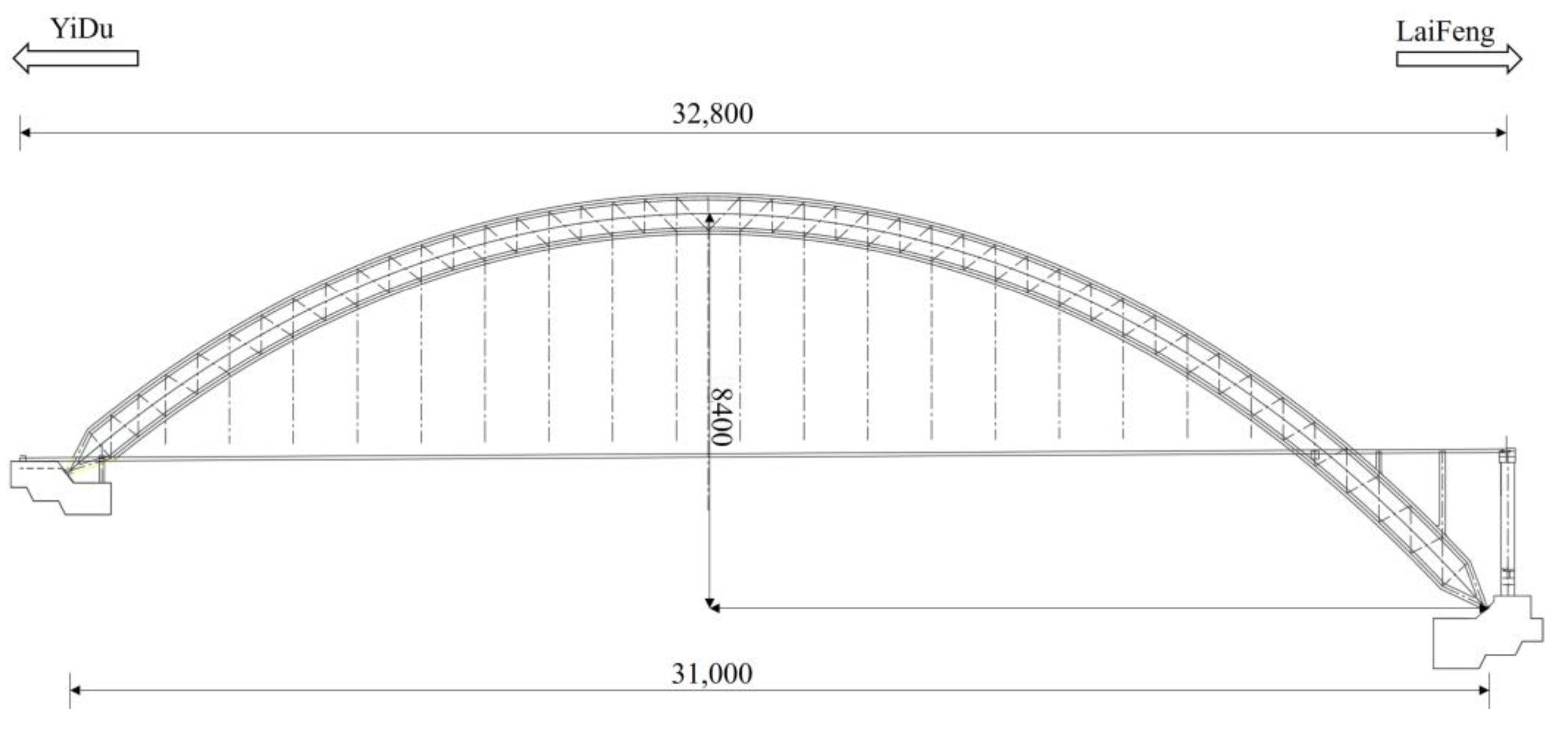
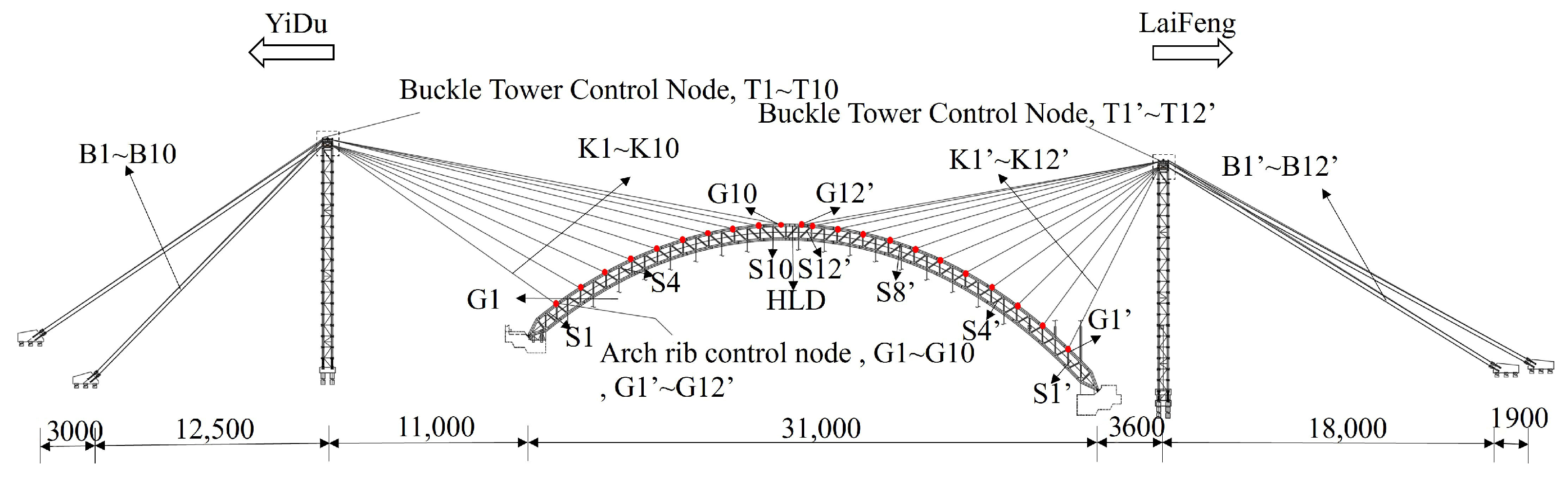
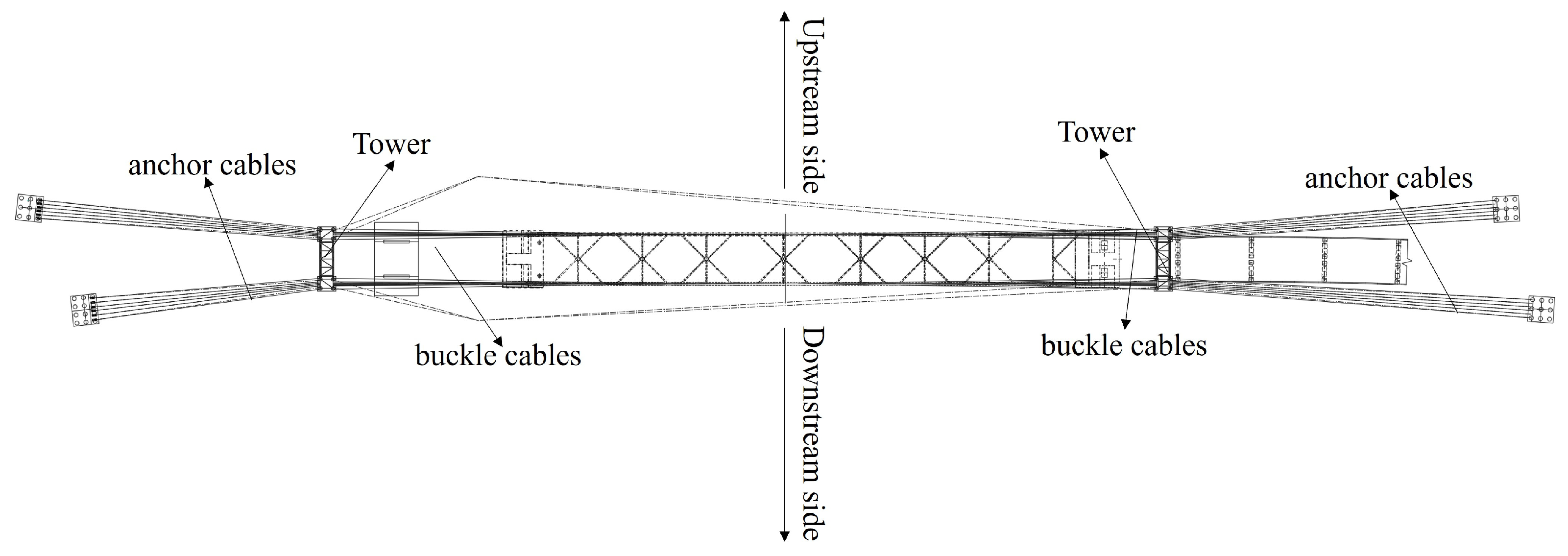
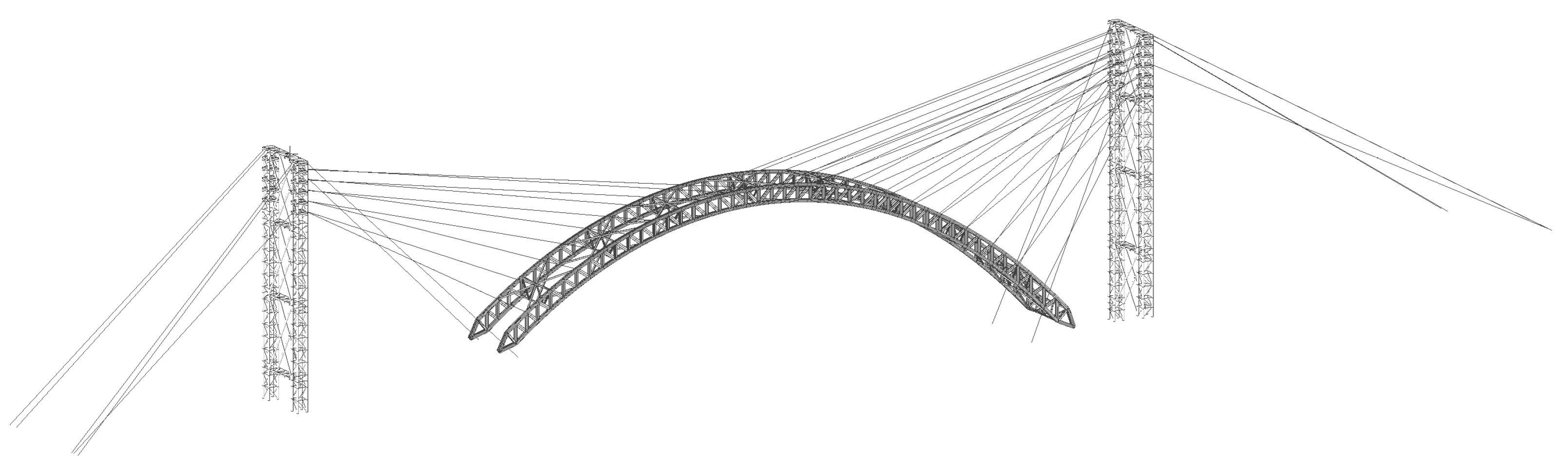
3. Engineering Application

3.1. Engineering Situations

The bridge is designed as an asymmetrical, two-hinged steel truss arch spanning 310 m. Its arch is based on a catenary curve that rises 84 m, yielding a rise-to-span ratio of 1:4 and an arch axis coefficient of m = 1.7. On the Yidu side, the starting point of the designed arch axis is horizontally offset by 28 m from the theoretical axis, while on the Laifeng side they coincide. The main arch ribs feature a constant cross-sectional height, with the center lines of the upper and lower chords separated by 7.5 m vertically. These ribs are arranged 27 m apart in the transverse direction and are connected by wind braces, which come in both V-shaped and K-shaped forms. The upper and lower chords of the arch ribs are constructed using box-shaped sections, whereas the web members incorporate a combination of box-shaped and I-beam sections. For the wind bracing system—including both the top and bottom ties as well as the diagonal braces—box sections are used throughout, with the web members of these braces taking on an H-shaped profile. At the arch’s abutment, the upper and lower chords merge into a single section that is supported by bearing plates and connected to a hinged arch foot axis. This hinge permits in-plane rotation, which helps reduce internal bending moments and gives the structure its two-hinged configuration.
The arch rib is divided into 23 sections, including 10 sections on the Yidu bank (arch rib section numbers S1~S10), 12 sections on the Laifeng bank (arch rib section numbers S1′ ~S12′), and one arch rib closure section (arch rib section number HLD), with a total of 44 unilateral buckle and anchor cables (buckle cable numbers K1~K10, K1′~K12′, anchor cable numbers B1~B10, B1′~B12′). There are a total of 88 buckled back cables in this bridge; because of its asymmetric structure, each buckle and anchor cable is solved separately. The anchorage points of the buckle cable and the arch rib are the control nodes of the arch rib, and the anchorage points of the buckle cable and the buckle tower are the control nodes of the buckle tower. The control node numbers of the arch rib and the buckled tower are the same as those of the unknown variables of the cable forces: arch rib control node numbers G1~G10, G1′~G12′ and buckle tower control node numbers T1~T10, T1′~T12′. The overall layout of the cable-stayed buckle system for this bridge is illustrated in Figure 6, Figure 7 and Figure 8.

3.2. Structural Calculation Model

In the construction phase, a comprehensive structural model was developed using MIDAS Civil-2024, incorporating the steel truss, buckle and anchor cables, and towers, as depicted in Figure 9. Truss elements were employed to simulate the buckle and anchor cables, while spatial beam elements represented the arch ribs and towers. The construction stage was divided into specific calculation conditions, as detailed in Table 1.

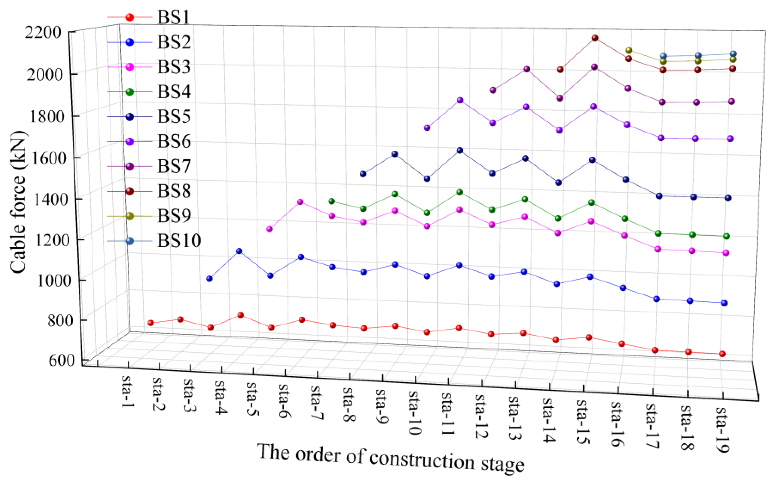
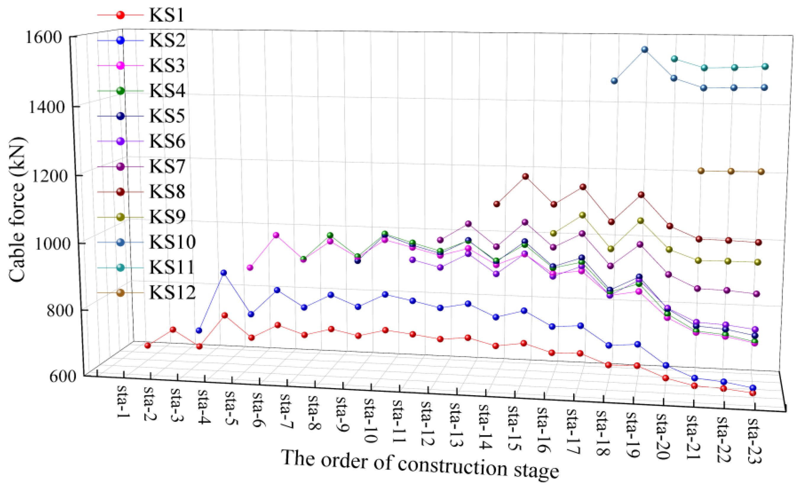
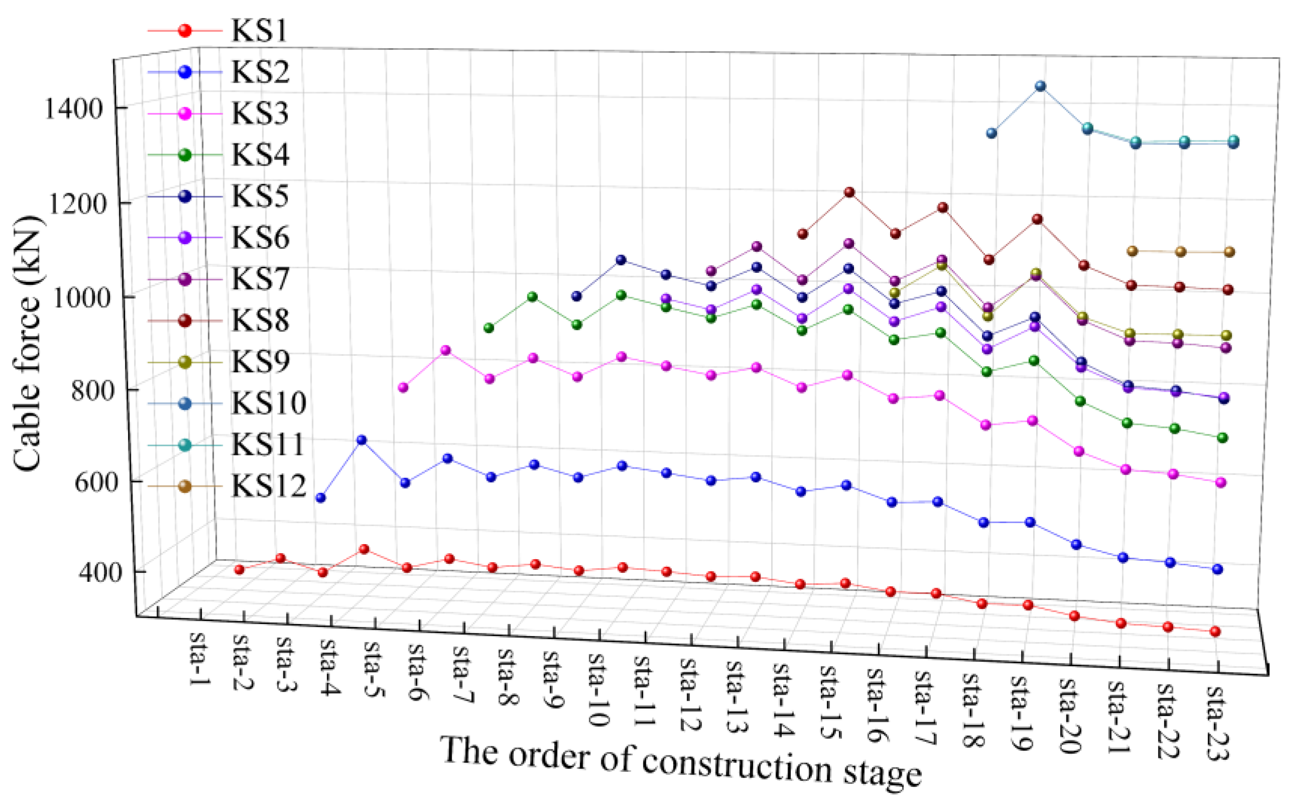
3.3. Optimization Results

Taking the ideal arch alignment under the one-time arching condition as the target alignment, the initial tensions of the buckle and anchor cables are calculated using the aforementioned method, as shown in Figure 10. It can be observed that the initial tensions of the buckle and anchor cables vary smoothly, with light differences in tensions between adjacent cables, and no obvious changes in cable tensions can be found, indicating good uniformity for the cable forces.
The arch ribs are constructed by the cable-stayed buckle cantilever construction at the closure and after loosening the cable; the displacement of the arch formation alignment and the displacement of the ideal arch alignment under the one-time arching condition are shown in Figure 11. The results demonstrate that the arch formation alignment closely aligns with the target shape, with the largest vertical displacement difference below 5 mm. Considering the combined effects of the buckle and anchor cables, the changes in the displacements of the cantilevered control nodes of various segments are gradual, indicating good continuity in the construction shape. The tower deviation during construction is shown in Figure 12; the maximum deflection is 0.032 m, highlighting the accurate control of tower deviation. The construction alignment of the arch rib and buckle tower moves up and down around the target alignment, showing periodic changes. The calculated displacements of the upstream and downstream control nodes are shown in Figure 13. As indicated, the alignment deviation between the upstream and downstream of the arch rib is basically zero.
Figure 14 illustrates the sectional stress distribution in the upper and lower chords of the arch rib. Consistent with arch mechanics principles, theoretical analysis predicts compressive stress dominance throughout the bare arch configuration. Due to the bridge’s unsealed construction process, the peak compressive stress does not occur at the arch foot but rather at the mid-span, measuring 49.4 MPa. The arch rib is constructed from Q345qD steel, which has a design strength value of 290 MPa [37], indicating that the observed compressive stress is well within the material’s safe capacity.
Due to space limitations, only the calculated results of the buckle and anchor cable forces on the upstream side during the construction stage are provided. The buckle and anchor cable forces in the construction stage are shown in Figure 15, Figure 16, Figure 17 and Figure 18. As indicated, the maximum difference in backstay cable forces between adjacent construction stages is 183 kN, confirming exceptional uniformity in the cable forces throughout the construction process.

3.4. Control Results

According to the field measurements, the measured vertical displacements of the arch rib alignment after loosening the cable are presented in Figure 19; the measured buckle tower deviations are shown in Figure 20, and the measured axial displacements of the arch ribs are given in Figure 21. Segments S1~S10 correspond to the Yidu side arch rib segments, and segments S1′~S12′ refer to the Laifeng side arch rib segments. As shown in Figure 19, after cable release and arch formation, the S8′ segment on the Laifeng side experiences a significant shape deviation, with a maximum offset of 3.4 cm. The primary cause for this deviation is the cumulative manufacturing errors in the steel structure of the S8′ segment on the Laifeng side, which could not be fully compensated by bolt gap adjustments during high-altitude assembly. As presented in Figure 20 and Figure 21, the maximum deflection of the tower during construction is 3.3 cm, and the maximum deviation interval between neighboring control nodes is 3.365 cm. Generally, the tower deviations remain relatively stable throughout the construction process. The maximum axial displacement of the arch rib is 5 cm. According to Technical Specification for Construction of Highway Bridge and Culvert (JTG/T F50-2011) [38], the allowable elevation displacement for arch ribs is the small value of ±L/3000 and ±5 cm; thus, it is for the arch bridge with a span of 310 m, taking ±5 cm as the tolerance. The allowable lateral axis displacement for the arch ring is ±L/6000, which is approximately ±5.17 cm for a span of 310 m. In short, the maximum deflections for the arch ribs and the arch ring satisfy the requirements of the specification, indicating the high shape control accuracy of the bridge.
Table 2 and Table 3 display the measured cable forces along with the corresponding errors for the upstream buckle and anchor cables under various tensioning control conditions. The data indicate that the theoretical and measured cable forces are in good agreement, with a maximum error of −4.81%. Notably, the cable forces measured on the Laifeng side are generally lower than the theoretical values. This discrepancy is attributed to manufacturing errors in the eighth segment of the arch rib, which result in an arch rib shape that is higher than expected. Additionally, assembly errors in subsequent segments further elevate the arch rib shape, necessitating a reduction in the tension of the buckle cables to control the arch rib shape error during construction. Concurrently, the anchor cable forces are reduced to manage the deviation of the buckle tower, which explains why the measured anchor cable forces are lower than the theoretical predictions.
Through statistical analysis of the theoretical versus measured cable forces on the Yidu and Laifeng sides, we find that the Yidu side has an RMSE of 31.78 kN, a standard deviation of 19.80 kN (2.19% RMSE, 1.31% relative standard deviation), and a mean error of +25.25 kN (+1.79%), indicating measurements that are consistently slightly high with low variability; the Laifeng side has an RMSE of 25.15 kN, a standard deviation of 24.07 kN (2.29% RMSE, 2.22% relative standard deviation), and a mean error of −8.79 kN (−0.73%), indicating measurements that are consistently slightly low but more variable. Thus, the Yidu side shows better measurement stability, while the Laifeng side requires attention to its greater error fluctuations; we recommend separately optimizing cable tension arrangements and calibrating the force-measuring devices to further improve measurement accuracy and structural safety.

4. Conclusions

In this study, a constrained optimization method is developed to enhance computational efficiency in determining the buckle and anchor cable forces under one-time tension during cable-stayed buckle construction. The approach ensures calculation accuracy and improves the uniformity of the construction alignment for the arch rib and buckle tower. The method is applied to a 310 m asymmetric steel truss arch bridge, verifying its effectiveness. The key findings are as follows:
(1)
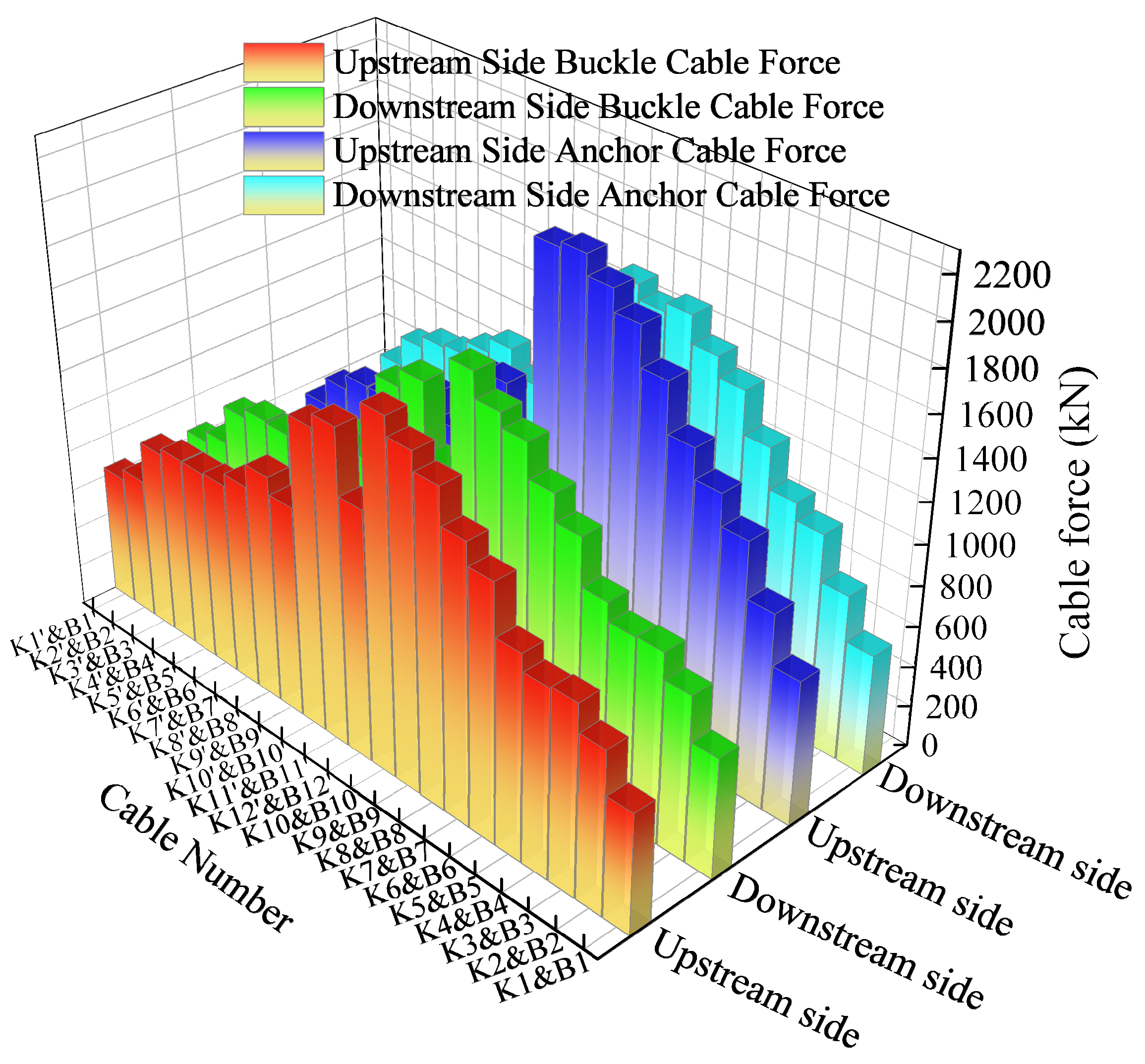
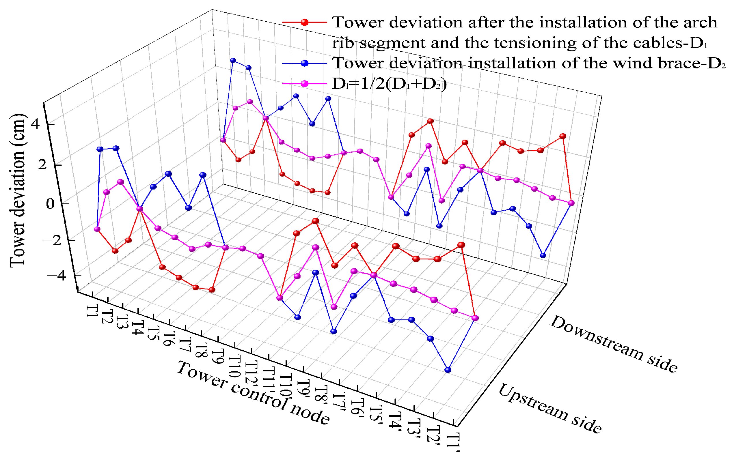
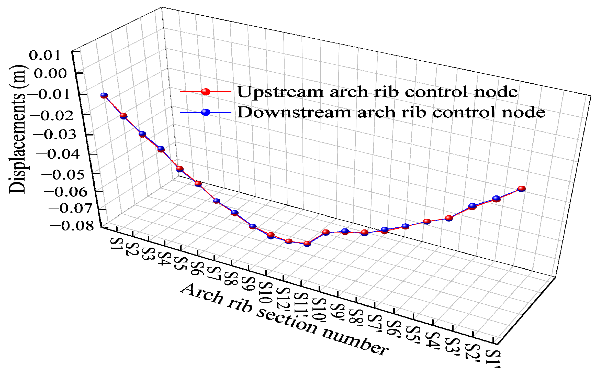
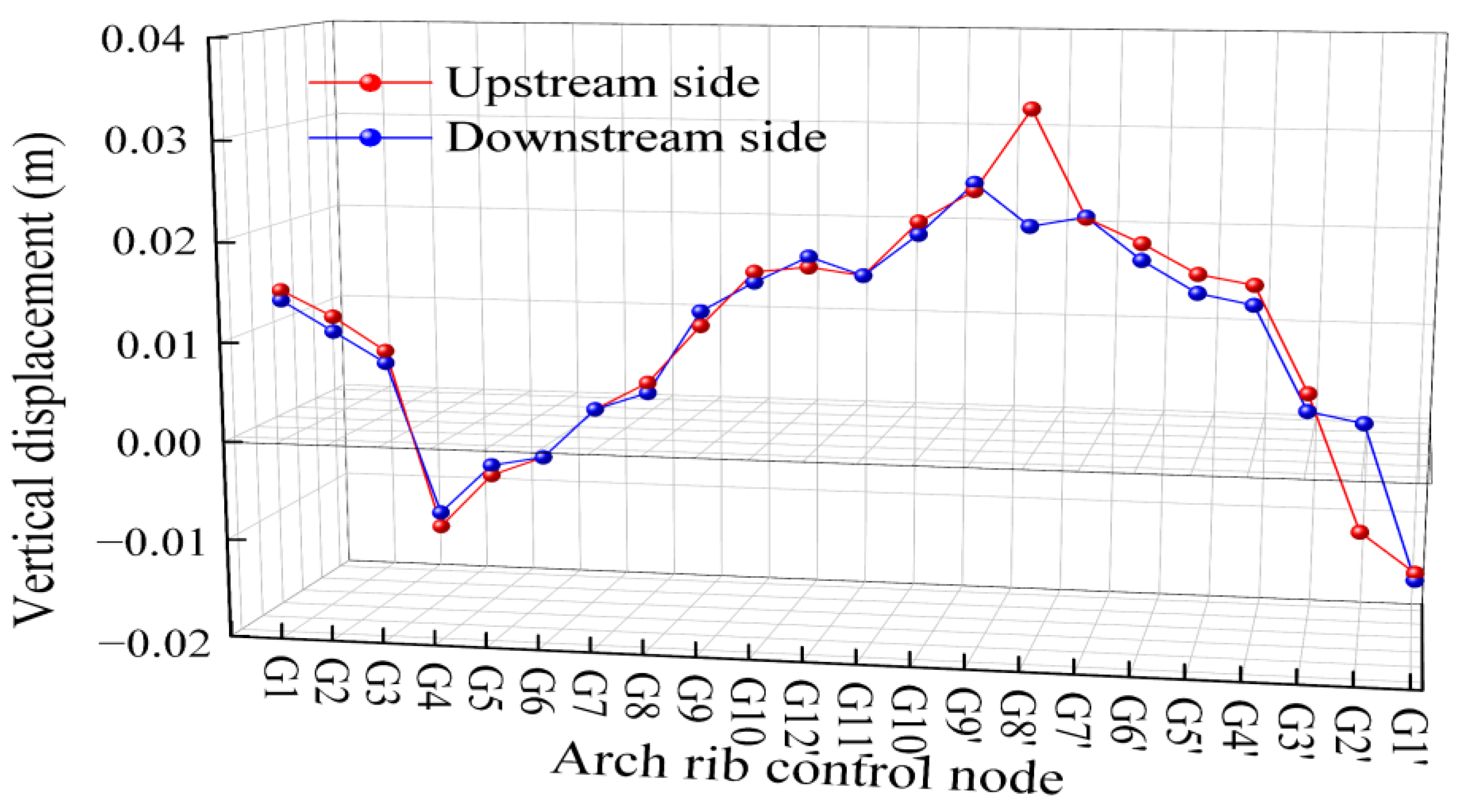
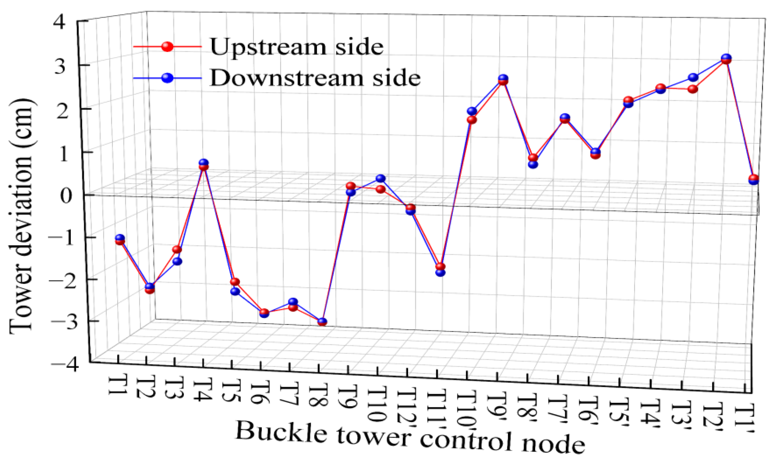
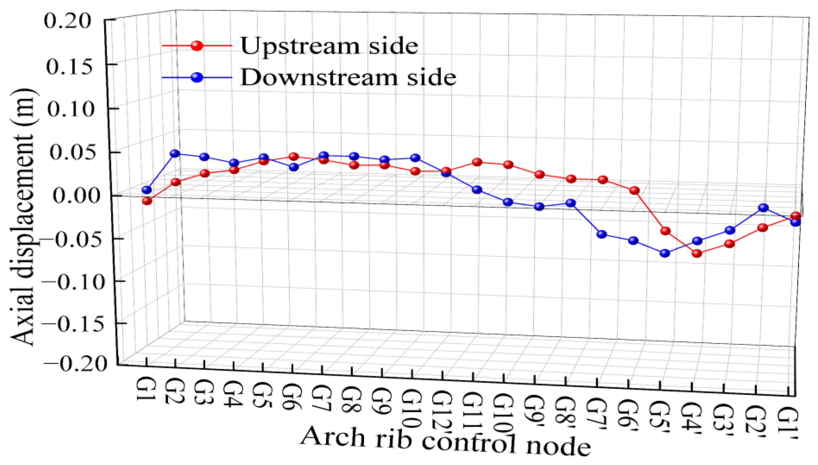
The experimental results show that the maximum deviation between the measured and theoretical cable forces during construction is 4.81%; the maximum difference in the measured and theoretical arch displacements after tensioning is 3.4 cm; and the maximum axial displacement of the arch rib is 5 cm. These findings indicate that the measured alignment, as well as the buckle and anchor cable forces, closely match theoretical values, meeting design and specification requirements.
(2)
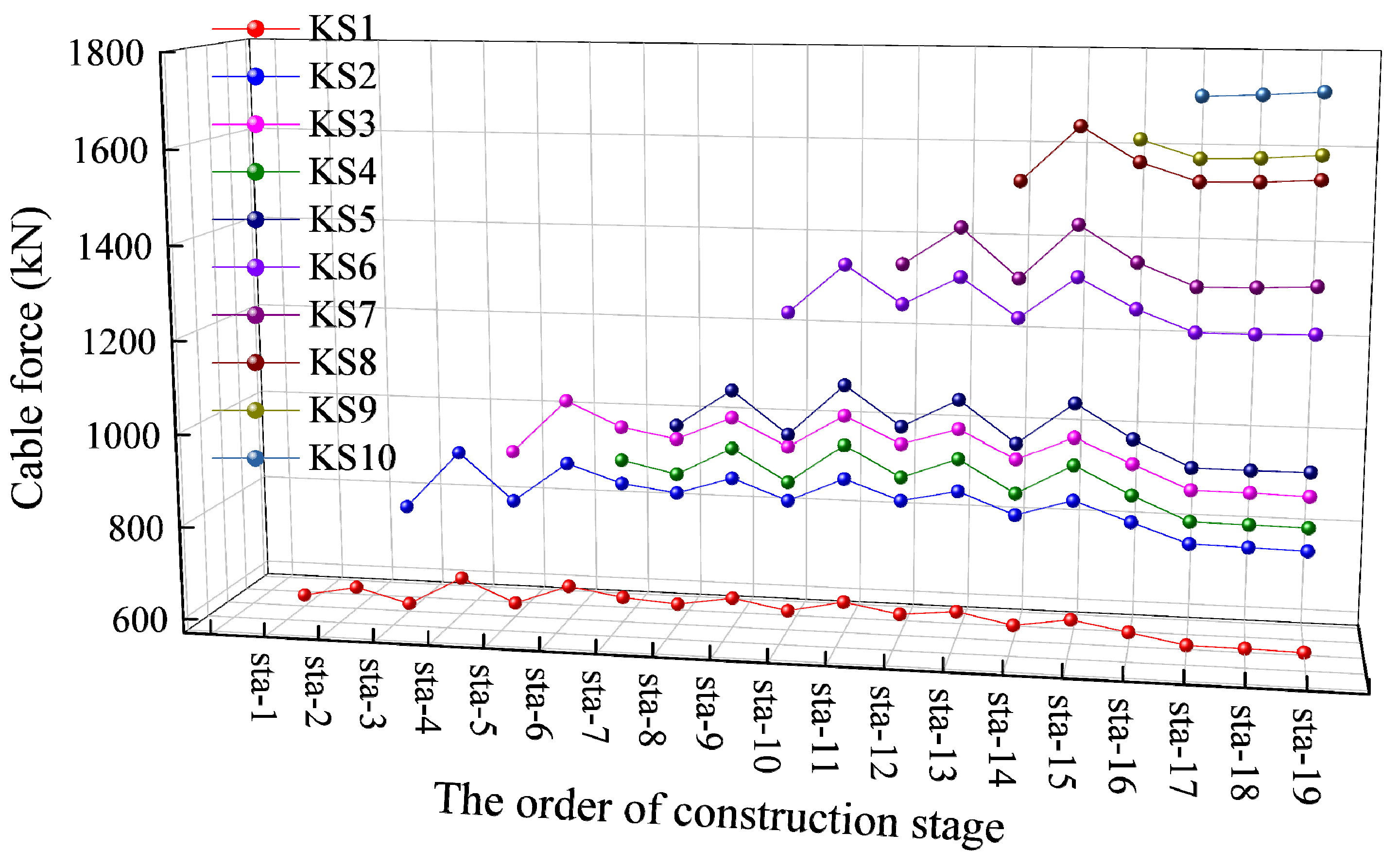
The proposed optimization method effectively controls fluctuations in arch rib alignment, tower deviation, and cable forces during construction, ensuring a stable arch shape. It enables a one-time calculation of buckle and anchor cable forces, eliminating iterative computations and simplifying the analysis process while enhancing the accuracy of theoretical arch alignment.
(3)
In this study, the constraint conditions did not account for the stress state of the arch rib during construction, nor did they comprehensively consider the bridge’s in-service stress conditions. Future research could incorporate arch rib axial forces during construction as optimization objectives, impose constraints on the bridge’s in-service stress state to enhance the model’s comprehensiveness and practical applicability, and perform a systematic sensitivity study of key parameters (e.g., cable tension and section stiffness) to further verify robustness.
(4)
The method proposed in this paper introduces a versatile workflow for extracting influence matrices and mapping constraints applicable to any staged finite-element model, offering a portable tool for construction control of arch bridges with diverse structural forms. It also lays the theoretical foundation for incorporating in-service axial forces, temperature effects, and other stress states into construction control and for developing real-time adaptive tensioning control systems.

Author Contributions

Conceptualization, methodology, validation, investigation, resources, writing—original draft preparation, writing—review and editing, visualization, X.Z.; software, validation, X.M.; validation, W.C.; formal analysis, W.X.; data curation, Y.K.; conceptualization, supervision, project administration, funding acquisition, Y.W. All authors have read and agreed to the published version of the manuscript.

Funding

The National Natural Science Foundation of China No. 52369023.

Data Availability Statement

The original contributions presented in this study are included in the article. Further inquiries can be directed to the corresponding author.

Conflicts of Interest

Authors Xuming Ma and Wei Chen were employed by the China Railway Bridge Science Research, Ltd. Author Yuan Kang was employed by the POWERCHINA SINOHYDRO ENGINEERING BUREAU 14 CO., LTD. The remaining authors declare that the research was conducted in the absence of any commercial or financial relationships that could be construed as a potential conflict of interest.

References

  1. Chen, B.C.; Liu, J.P. Review of construction and technology development of arch bridges in the world. J. Transp. Eng. 2020, 20, 27–41. [Google Scholar]
  2. Liang, Y.; He, W.; Tang, M.L. State of The Art Review of Bridge Aesthetics in 2020. J. Civ. Environ. Eng. 2021, 43, 234–241. [Google Scholar]
  3. Xia, H.; Xu, H.; Yi, Y.J. Main Bridge Design of Wujiang River Bridge of Dejiang-Yuqing Expressway. World Bridges 2023, 51, 14–21. [Google Scholar]
  4. Rajagopalan, G.; Karnik, M.; Pulkkinen, P. Chenab Bridge-Constructing the World’s Tallest Railway Bridge. Struct. Eng. Int. 2023, 33, 232–237. [Google Scholar] [CrossRef]
  5. Liu, X.H.; Chen, F.M.; Zeng, Y.Z. Overall Design of Fenglai Bridge in Chongqing. Bridge Constr. 2023, 53, 101–107. [Google Scholar]
  6. Zhou, S.X. The Study of Effect on Capacity of CFST Arch Bridge with Steel Tube Initial Stress; Chongqing University: Chongqing, China, 2007. [Google Scholar]
  7. Wang, P.H.; Tang, T.Y.; Zheng, H.N. Analysis of Cable-Stayed Bridges during Construction by Cantilever Methods. Comput. Struct. 2004, 82, 329–346. [Google Scholar] [CrossRef]
  8. Sun, S. Study on Determination Method of Reasonable Construction State in Hoisting Process of Long-Span Concrete Filled Steel Tube Arch Bridge; Changsha University of Science and Technology: Changsha, China, 2017. [Google Scholar]
  9. Wu, H.J.; He, L.; Wang, S.R. Geometry Control Method Based on Stress-Free State Theory For Long Span Concrete Filled Steel Tube Arch Bridge. Bridge Constr. 2020, 50, 20–26. [Google Scholar]
  10. Yao, G.W.; Chao, Y.; Wu, H.J. Construction Control of Hoisting and Installation of Arch Rib of a Half-Through CFST Stiff Skeleton Arch Bridge. Bridge Constr. 2017, 47, 107–111. [Google Scholar]
  11. Xu, Y.; Shen, C.Y.; Zhu, Y.B. Improved iteration algorithm for determination of tension of buckle stays for cantilever construction of Arch Bridge. Bridge Constr. 2016, 46, 65–69. [Google Scholar]
  12. Yu, Y.J.; Luo, Y.Q.; Zhou, W. A Combined Algorithm for the Buckle Stay Force Determinations in Cantilever Construction by Synthesizing the Zero-Displacement and Zero-Stress State Control Methods. Adv. Eng. Sci. 2024, 3–4, 1–8. [Google Scholar]
  13. Li, Y.; Wang, J.L.; Ge, S.S. Optimum calculation method for cable force of concrete filled steel tube arch bridge in inclined cable-stayed construction. J. Highw. Transp. Res. Dev. 2017, 11, 42–48. [Google Scholar] [CrossRef]
  14. Gu, Y.; Yao, C.R.; Li, Y.D. Study of alignment control method for installation of arch ribs of long span CFST arch bridge. Bridge Constr. 2014, 44, 107–113. [Google Scholar]
  15. Jia, Y.; Wei, C.; Huang, Z. Cable Force Calculation of Cable Hoisting of CFST Arch Bridge Research. Buildings 2023, 13, 2370. [Google Scholar] [CrossRef]
  16. Liu, Z.W.; Zhou, S.X.; Zou, K.R. A numerical analysis of buckle cable force of concrete arch bridge based on stress balance method. Sci. Rep. 2022, 12, 12451. [Google Scholar] [CrossRef]
  17. Tian, Z.C.; Peng, W.P.; Zhang, J.R. Determination of initial cable force of cantilever casting concrete arch bridge using stress balance and influence matrix methods. J. Cent. South Univ. 2019, 26, 3140–3155. [Google Scholar]
  18. Li, Y.D.; Yao, C.R.; Liang, Y. On Technical Advancement and Challenge of Arch Bridges. Bridge Constr. 2012, 42, 13–20. [Google Scholar]
  19. Zheng, J.L.; Wang, J.J.; Mou, T.M. The Design and Construction Feasibility Study of 700m Scale Concrete Filled Steel Tubular Arch Bridge. Eng. Sci. 2014, 16, 33–36. [Google Scholar]
  20. Zhang, Z.C.; Ye, G.R.; Wang, Y.F. Optimization of Stayed-Buckle Cable Forces During Adjustment of the Line-Shape on Long Span Arch Bridge. Eng. Mech. 2004, 6, 187–192. [Google Scholar]
  21. Zhang, J.M.; Zheng, J.L.; Xiao, R.C. Calculation Method for Optimizing the Installation Process of Concrete-Filled Steel Tube Arch Bridge. China J. Highw. Transp. 2005, 18, 40–44. [Google Scholar]
  22. Zhou, Q.; Zhou, J.T.; Ma, H. Improved algorithm of cable force for one-time cable tension on Steel tube arch ribs with segmental hoisting. J. Traffic Transp. Eng. 2020, 20, 92–101. [Google Scholar]
  23. Qin, D.Y.; Zheng, J.L.; Du, H.L. Optimization Calculation Method for Stayed-Buckle Cable Force under One-Time Tension by Buckle Stay Method and Its Application. China Railw. Sci. 2020, 41, 52–60. [Google Scholar]
  24. Zhou, Y.; Wang, Y.; Zhou, J.T. Arch Forming Calculation Theory and Control Method of 500m Steel Tube Arch Bridge, China. J. Highw. Transp. 2022, 35, 60–72. [Google Scholar]
  25. Song, C.L.; Xiao, R.C.; Sun, B. Cable force optimization of cable-stayed bridges: A surrogate model-assisted differential evolution method combined with B-Spline interpolation curves. Eng. Struct. 2023, 283, 115856. [Google Scholar] [CrossRef]
  26. Tian, Z.; Zhang, Z.; Ning, C. Multi-objective optimization of cable force of arch bridge constructed by cable-stayed cantilever cast-in-situ method based on improved NSGA-II. Structures 2024, 59, 105782. [Google Scholar] [CrossRef]
  27. Dai, Y.W.; Wang, Y.Y. A research to cable force optimizing calculation of cable-stayed arch bridge. Procedia Eng. 2012, 37, 155–160. [Google Scholar]
  28. Timoshenko, S.P.; Gere, J.M. Theory of Elastic Stability; M. Courier Corporation: Chelmsford, MA, USA, 2012. [Google Scholar]
  29. Huang, Y.; Xu, Y.; Chen, S. Research on Solution Method for Cable-Stayed Bridge Formation Based on Influence Matrix and Interior Point Method. Buildings 2025, 15, 673. [Google Scholar] [CrossRef]
  30. Byrd, R.H.; Gilbert, J.C.; Nocedal, J. A Trust Region Method Based on Interior Point Techniques for Nonlinear Programming. Math. Program. 2000, 89, 149–185. [Google Scholar] [CrossRef]
  31. Waltz, R.A.; Morales, J.L.; Nocedal, J.; Orban, D. An interior algorithm for nonlinear optimization that combines line search and trust region steps. Math. Program. 2006, 107, 391–408. [Google Scholar] [CrossRef]
  32. Byrd, R.H.; Hribar, M.E.; Nocedal, J. An Interior Point Algorithm for Large-Scale Nonlinear Programming. SIAM J. Optim. 1999, 9, 877–900. [Google Scholar] [CrossRef]
  33. Mohammadzadeh, S.; Miri, A.; Nouri, M. Enhancing the structural performance of masonry arch bridges with ballast mats. J. Perform. Constr. Facil. 2017, 31, 04017089. [Google Scholar] [CrossRef]
  34. Lonetti, P.; Pascuzzo, A. Optimum Design Analysis of Hybrid Cable-Stayed Suspension Bridges. Adv. Eng. Softw. 2014, 73, 53–66. [Google Scholar]
  35. Dan, Q.L.; Qin, S.Q.; Wei, K. Equation for Geometric Shape Control of Structure Formed in Stages Based on Plane Beam Elements. Bridge Constr. 2017, 47, 42–47. [Google Scholar]
  36. Yuan, R.A.; Qin, S.Q. Application of Unstressed State Method to Construction of Steel Strand Stay Cable. Bridge Constr. 2012, 42, 75–79. [Google Scholar]
  37. GB50017-2020; Code for Design of Steel Structure. Ministry of Housing and Urban-Rural Development of China: Beijing, China, 2020.
  38. JTG/TF50-2011; Technical Specification for Construction of Highway Bridge and Culvert. Ministry of Transport of China: Beijing, China, 2011.
Figure 1. Schematic diagram of model modification.
Buildings 15 01529 g001
Figure 2. The schematic diagram of the influence of cable tension on the displacement of the structure.
Buildings 15 01529 g002
Figure 3. The schematic diagram of the influence of tension cable force on the cable force of other cables.
Buildings 15 01529 g003
Figure 4. The schematic diagram of the influence on the arch rib displacement when removing the cable.
Buildings 15 01529 g004
Figure 5. Calculation flow of the initial tension of the buckle and anchor cables in the construction phase.
Buildings 15 01529 g005
Figure 6. General plan of the bridge (unit: cm).
Buildings 15 01529 g006
Figure 7. Layout elevations of cable-stayed buckle system of the bridge.
Buildings 15 01529 g007
Figure 8. Layout plan of cable-stayed buckle system of the bridge.
Buildings 15 01529 g008
Figure 9. Finite element calculation model.
Buildings 15 01529 g009
Figure 10. Initial tension of cables in the construction process of an arch bridge.
Buildings 15 01529 g010
Figure 11. Displacement diagram of arch rib control node.
Buildings 15 01529 g011
Figure 12. Tower deviation diagram for tower control node calculation.
Buildings 15 01529 g012
Figure 13. The calculated displacements of the upstream and downstream control nodes.
Buildings 15 01529 g013
Figure 14. Sectional stress of upper and lower chords of arch rib.
Buildings 15 01529 g014
Figure 15. Buckle cable forces calculation in the construction stage of the upstream side on the Yidu side.
Buildings 15 01529 g015
Figure 16. Anchor cable forces calculation in the construction stage of the upstream side on the Yidu side.
Buildings 15 01529 g016
Figure 17. Buckle cable forces calculation in the construction stage of the upstream side on the Laifeng side.
Buildings 15 01529 g017
Figure 18. Anchor cable forces calculation in the construction stage of the upstream side on the Laifeng side.
Buildings 15 01529 g018
Figure 19. The measured vertical displacements of the arch ribs.
Buildings 15 01529 g019
Figure 20. The measured deviations of the buckle tower.
Buildings 15 01529 g020
Figure 21. The measured axial displacements of arch ribs.
Buildings 15 01529 g021
Table 1. Calculation condition division of the construction stage.
Working
Condition
Construction StateWorking
Condition
Construction State
1Tower Construction20Segment 10 + Buckle and Anchor Cable 10
2Wind-Resistant Cable Installation21Remaining Diagonal Braces of the Second Section of Wind Brace
3Segment 1 + Buckle and Anchor Cable 122Segment 11 + Buckle and Anchor Cable 11
4Removal of Temporary Support of Arch Rib23Segment 12 + Buckle and Anchor Cable 12
5Segment 2 + Buckle and Anchor Cable 224Closure Segment Assembly
6The Sixth Section of Wind Brace25The First Section of Wind Brace
7Segment 3 + Buckle and Anchor Cable 326Remove Buckle and Anchor Cable 12
8The Fifth Section of Wind Brace27Remove Buckle and Anchor Cable 11
9Segment 4 + Buckle and Anchor Cable 428Remove Buckle and Anchor Cable 10
10Transverse Connections and Oblique Web Members of the Fourth Section of Wind Brace29Remove Buckle and Anchor Cable 9
11Segment 5 + Buckle and Anchor Cable 530Remove Buckle and Anchor Cable 8
12Remaining Diagonal Braces of the Fourth Section of Wind Brace31Remove Buckle and Anchor Cable 7
13Segment 6 + Buckle and Anchor Cable 632Remove Buckle and Anchor Cable 6
14Segment 7 + Buckle and Anchor Cable 733Remove Buckle and Anchor Cable 5
15Transverse Connections and Oblique Web Members of the Third Section of Wind Brace34Remove Buckle and Anchor Cable 4
16Segment 8 + Buckle and Anchor Cable 835Remove Buckle and Anchor Cable 3
17Remaining Diagonal Braces of the Third Section of Wind Brace36Remove Buckle and Anchor Cable 2
18Segment 9 + Buckle and Anchor Cable 937Remove Buckle and Anchor Cable 1
19Transverse Connections and Oblique Web Members of the Second Section of Wind Brace
Table 2. The measured cable forces and errors of the cable forces on Yidu side under cable tension condition.
NumberTheoretical Cable Force (kN)Measured Cable Force (kN)Error
K-15956143.20%
B-17137221.30%
K-28058242.40%
B-29569701.42%
K-39379450.81%
B-3122012321.01%
K-4927919−0.82%
B-413691355−1.00%
K-5100710191.15%
B-5150815442.42%
K-6125712922.78%
B-6174117611.14%
K-7136514254.38%
B-7192719752.51%
K-8154215883.01%
B-8202920591.48%
K-9163116752.70%
B-9212321451.02%
K-10172017652.61%
B-10209821462.31%
Table 3. The measured cable forces and errors of the cable forces on Laifeng side under cable tension condition.
Number.Theoretical Cable Force (kN)Measured Cable Force (kN)Error
K-1′645640−0.71%
B-1′347341−1.71%
K-2′700694−0.90%
B-2′521521−0.07%
K-3′902892−1.09%
B-3′777759−2.37%
K-4′9349400.68%
B-4′9159180.28%
K-5′9359622.93%
B-5′99010112.16%
K-6′9449722.99%
B-6′99010233.35%
K-7′100610191.28%
B-7′105210631.00%
K-8′11181064−4.81%
B-8′11361090−4.05%
K-9′10371026−1.04%
B-9′1016993−2.23%
K-10′14801445−2.39%
B-10′13541319−2.61%
K-11′15441528−1.04%
B-11′13681351−1.23%
K-12′12301188−3.39%
B-12′11161087−2.61%
Disclaimer/Publisher’s Note: The statements, opinions and data contained in all publications are solely those of the individual author(s) and contributor(s) and not of MDPI and/or the editor(s). MDPI and/or the editor(s) disclaim responsibility for any injury to people or property resulting from any ideas, methods, instructions or products referred to in the content.

