Article

An Innovative Approach to Enhancing Concrete Sustainability: Utilising Unprocessed Steel Slag with Low CaO and High SiO2 Content

by
Bengin M. A. Herki
1,*,
Ali Ibrahim Ali
2,
Yousif Sadiq Smail
2 and
Karwan Maroof Omer
2
1
Civil and Environmental Engineering Department, Faculty of Engineering, Soran University, Soran 44008, Iraq
2
Darin Steel Factory, Kawergoask Road, Khabat District, Erbil 44001, Iraq
*
Author to whom correspondence should be addressed.
Buildings 2025, 15(9), 1514; https://doi.org/10.3390/buildings15091514
Submission received: 21 March 2025 / Revised: 15 April 2025 / Accepted: 20 April 2025 / Published: 1 May 2025
(This article belongs to the Section Building Materials, and Repair & Renovation)

Abstract

As a non-biodegradable material and a major environmental hazard due to its discharge into the environment, by-products like steel production steel slag (SS) are disposed of in open spaces, agricultural lands, and close to residential areas. This by-product is now considered to have qualities that make it a potential substitute for cement and natural aggregates in the manufacturing of concrete or clinker in the cement manufacturing sector. The effects of using a novel type of SS made in an induction furnace (IF) in place of Portland cement and natural coarse aggregate in concrete were investigated experimentally. Steel slag powder (SSP), low-density steel slag (LDSS) aggregate, and high-density steel slag (HDSS) aggregate were all physically and chemically examined in this study. Each of these three replacement materials was added to concrete in weight proportions of 20%, 40%, and so on. The performance of the resultant mixtures was compared to that of the plain concrete, and the mechanical properties such as split tensile strength, flexural strength, and compressive strength were examined, along with the durability properties of water absorption (WA) and freeze–thaw, and the non-destructive testing of ultrasonic pulse velocity (UPV) of the concrete mixtures were also evaluated. The results indicated that adding HDSS to the concrete increased its mechanical and durability properties, while adding LDSS and SSP resulted in a small and a significant drop in mechanical properties, respectively, when compared to the plain concrete. The increase in compressive strength and the decrease in water absorption at the standard age of 28 days reached 5.2% and 2.1%, respectively. The percentage decrease in compressive strength (8.95–21.74%) of SS concrete mixtures after freeze–thaw cycles was greater than that of the control concrete. Additionally, a concrete mixture containing 40% HDSS yielded the best results.

1. Background

One of the biggest global sources of CO2 emissions, the building industry, has a major impact on environmental pollution and climate change. The International Energy Agency (IEA) estimates that, in 2022, the building and construction industry accounted for over 37% of all energy-related CO2 emissions worldwide, divided between emissions from operations and emissions from building materials including steel, aluminium, and cement [1,2]. Last year, over 4 billion tons of cement were produced, about one ton for every two people. This amount is predicted to rise to 6 billion tons over the next five years, by 2030, with a compound annual growth rate (CAGR) of about 6% throughout the 2024–2030 prediction period. Even though the cement and concrete sectors have collaborated over the last ten years to continuously improve production methods and product standards to lessen their negative environmental consequences, the present CO2 reduction strategies might not be enough on their own. It would be ideal to focus on recycling industrial wastes and by-products, which is another environmental issue, as an alternate solution to the current situation because it is impossible to stop the manufacture of cement and concrete. Together with emissions from other combustion systems like iron and steel production plants, the cement industry contributes significantly to global climate change when one considers that its CO2 emissions make up around 8% of all CO2 emissions from stationary sources, making it the second-largest contributor to global warming after oil. With a combined yearly production capacity of 47 million tons, Iraq now has 18 public-sector and 13 private-sector cement production plants. Public enterprises contribute 18 million tons of cement to this capacity, while private sector companies contribute 29 million tons. There are seven cement plants in the Kurdistan region; six of them are already in operation, and one is being established in Erbil. Although the combined capacity of these cement companies is 16.936 million tons, they are now producing 10.7 million tons, or 64% of their capability [3].
The cement and concrete industries are becoming more interested in finding substitute materials to replace natural resources because of economic and environmental concerns [4,5,6]. Therefore, a significant amount of research has been done to see if it is possible to use some by-products, like steel slag (SS), as components for concrete and cement. As an alternative, some SS types with high pozzolanic qualities are utilized in the manufacturing of cement clinker, which lowers both CO2 emissions and the overall cost of the materials used. Therefore, as part of the green supply chain of waste-to-resources, SS, industrial by-products of steel production, are created in enormous quantities each year and should be considered as a green resource [1,7,8,9]. Because there has been no use for SS, a solid waste product of the iron and steel industry, over the previous century, piles of SS can be seen in some developed and almost all developing countries. The biggest problem facing the steel industry is slag disposal because it takes up a considerable amount of space (Figure 1). Due to the alkaline leachates from SS, the dumping of SS in open areas surrounding towns and on agricultural land in villages frequently poses a risk of soil and water contamination. It is produced using a variety of furnace types and methods; the electric arc furnace (EAF) and the basic oxygen furnace (BOF) are the two main types of furnace. Although the type of production has a significant impact on the chemical composition of SS documented in the literature, in general, the main chemical elements of SS are Fe2O3, CaO, MgO, MnO, and SiO2, and its significant compounds are C2S and C4AF. Steel slags contain significant amounts of oxides, including Fe oxides, MgO, MnO, and Al2O3. These oxides interfere with alite (C3S) crystallization and instead favour the formation of other minerals such as C2S, C4AF, and RO-phase (solid solution of FeO, MgO, MnO) [10,11,12,13,14,15,16].
Around 280 million tons of SS were produced annually worldwide in 2023; over 21 million tons were produced in Europe (of which, more than 70% is recycled), about 14 million tons in Japan, about 6 million tons in Turkey, and over 100 million tons in China and India (of which about 30% was used in the manufacture of cement and chemical admixtures to produce concrete, brick, and blocks in China). The US and other developed countries typically consume 70–80% of the SS, while Australia uses 60–70%. In contrast, India uses less than 20% of the SS it generates, and developing countries use even less [2,13]. No data are available on steel slag utilisation in Iraq and the Kurdistan region. SS is currently used in a variety of civil engineering applications, including as sand and gravel in concrete, as asphalt materials in highways, as a clinker material in the cement production process, as ballast for railways, as fertilizers, soil improvement, water pollution control, and as a filling material in several excavations. However, its release into the environment in the past could pose a serious environmental threat. Therefore, adequate action should be taken into consideration. About 60% of all steel slag produced in the US is utilized directly as road base, with the remaining 11% going toward fill, 11% toward asphalt concrete, and 5% toward the creation of cement clinker [12,17,18,19]. Important projects involving sustainable building materials have been started in the construction industry in recent years, and several studies have assessed the viability of using SS aggregate for concrete production. In one study [20], the engineering performance of concrete produced with SS aggregate were compared with concrete made with crushed natural aggregate. The investigators made concretes with a 0.4 W/C ratio and a cement quantity of 400 kg/m3, and the replacements in concretes with SS aggregate were chosen from 45% to 65%. They found that specimens containing SS aggregate had a higher compressive strength than specimens with natural aggregates, and that concrete mixes containing SS had a higher specific bulk gravity than concrete mixtures containing natural aggregates. There have been other reports of similar outcomes [21,22,23,24]. The use of SS in concrete as a partial substitute for natural coarse aggregates was examined in another recently released study [19]. The results demonstrated that the best replacement percentage for SS is 30% to obtain the appropriate compressive, flexural, and tensile strengths [19]. However, there are some technical problems that hinder the widespread use of SS, including volumetric instability, inconsistency of chemical composition, high porosity and absorption capacity, environmental concerns of heavy metal leaching, and lack of standards [25].
The reconstruction of Iraq and Kurdistan region cities started in 2003, and since then the growth of cities has led to the consumption of vast amounts of natural resources. Twelve of the 15 steel and iron plants that currently exist in Iraq are located in the Kurdistan region. Together, these factories can produce 4.6 million tons of steel and iron annually, which are split among the following provinces: Mosul has 50,000 tons, Duhok has 50,000 tons, Karbala has 200,000 tons, Basra has 350,000 tons, Sulaymaniyah has 1.88 million tons, and Erbil has 2.06 million tons [3]. In 12 steel factories in the Kurdistan region of Iraq, there is a yearly production of approximately 3.8 million tons, of which more than one million tons is consumed within the region and the remainder is exported to other parts of Iraq. About 100–150 kg SS is coproduced for 1000 kg steel. However, according to the local technical staff of steel production factories, the amount of SS produced as a by-product depends on the type of steelmaking process used, and a general estimate is that, for every ton of steel produced, about 7–10% of the ton of slag is produced. Therefore, SS varies from 266,000 to 380,000 tons to produce 3,800,000 tons of steel in this small region annually. One of the ongoing challenges in Iraq and the Kurdistan region, like other developing countries, is the accumulation and management of construction and demolition waste and industrial by-products. The excessive use of natural resources in construction has prompted civil and environmental engineers in Iraq to find alternative materials to used in civil engineering projects. Another issue in the reconstruction process of Iraq and the Kurdistan region which still exists is the reluctance of construction companies to reuse and/or use recycled and waste materials in projects due to lack of awareness and engineering knowledge. Other difficulties are regulatory barriers and the inconsistent enforcement of laws and lack of infrastructure for construction material waste recycling in the region. Some people still believe that using waste and recycled materials in their projects is not an engineering option. They do not know that some construction and demolition waste and industrial by-products are materials of high quality, and they are resources only. The connection between steel, by-products, and the cement, concrete, and asphalt industries is well established from a sustainable development perspective in developed countries. Nevertheless, in developing countries this cooperation has not been established. Therefore, in developing countries such as Iraq, including the Kurdistan region, investigations should be conducted on the by-products recycling of iron and steel factories and the environmental treatment of waste. Like in developed nations, developing nations should encourage collaboration among engineers, researchers, and businesses (academic-industry collaboration). Additionally, local, regional, and federal governments should support the application areas developed by implementing new legislation. Additionally, it appears that scientific and technical collaboration between developed and developing countries is urgently needed for recycling applications [26].
This study’s main goal is to investigate how the properties of concrete are affected when a novel type of SS is used in place of some of the cement and natural coarse aggregates. As previously stated, the physical and chemical characteristics of each SS vary based on the type of steel production furnace being utilised. However, to the best of the authors’ knowledge and after reviewing the readily available recently published literature, such as review articles [2,13], there are only a few pieces of research that demonstrate the usage of SS with low CaO and high SiO2. This is despite some studies utilising SS with similar physical properties. Induction furnace (IF) slag’s unusual composition leads to its frequent disposal as non-usable waste. This study supports a circular economy strategy by scientifically confirming its potential as a replacement, turning an underutilized by-product into a useful part of green concrete, lowering the amount of natural materials used and the load on landfills. Because of the CaO-rich profile (41% CaO and 18% SiO2 for conventional SS, approximately) typically preferred in slag applications, the application of IF steel slag (15.61% CaO and 38.73% SiO2 for SS used in this study) in concrete has been relatively unexplored up to this point. This study broadens the range of materials that can support sustainable concrete technology by establishing a new paradigm for the use of this novel steel slag. Physical, chemical, workability, mechanical (including compressive, tensile, and flexural strengths), durability (including water absorption and freeze–thaw resistance), and non-destructive testing of ultrasonic pulse velocity (UPV) are the engineering properties that are investigated in this study. Therefore, it is necessary to determine the optimum usage replacement ratio of this type of SS in terms of mechanical capabilities, durability characteristics, and sustainability.

2. Materials and Experimental Procedure

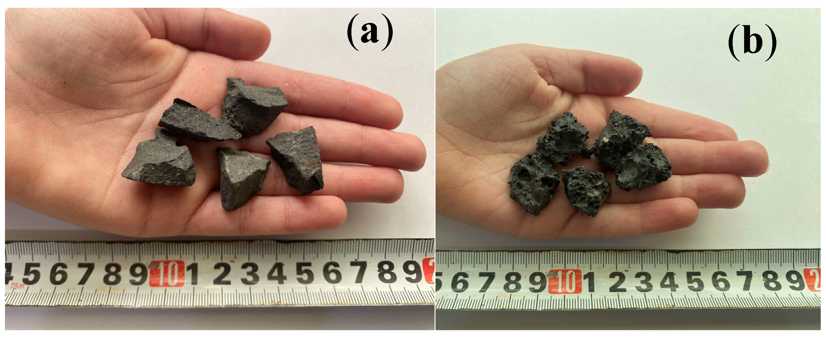
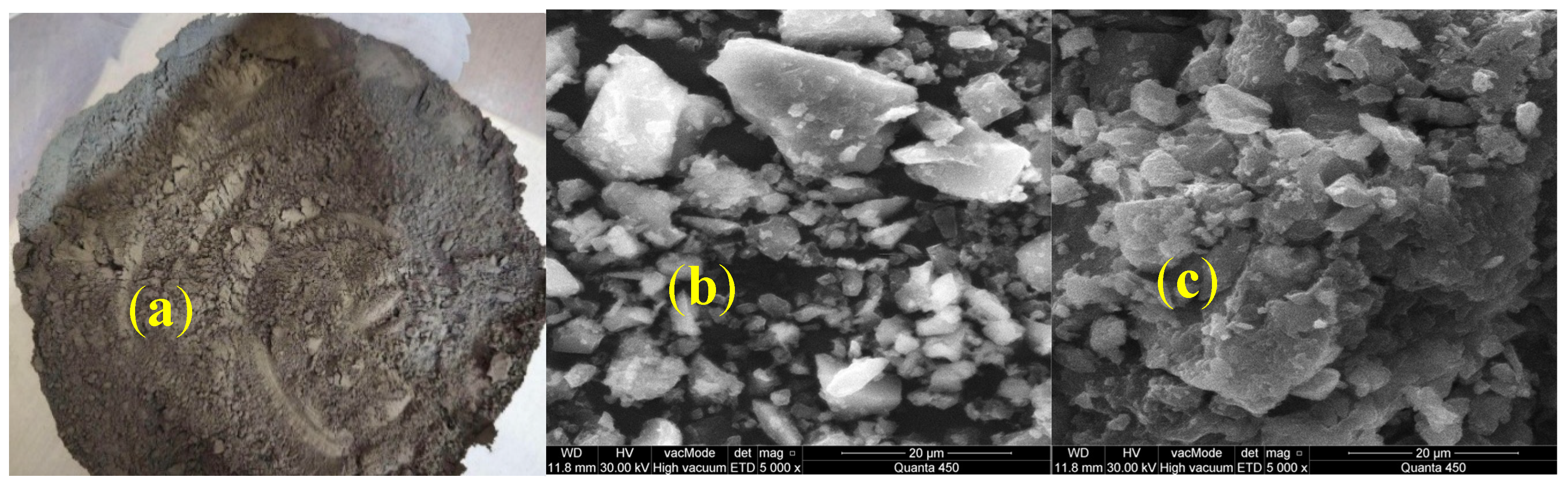
2.1. Steel Slag (SS)

Steel slag (SS) is a by-product of the steel manufacturing process that comes in a variety of forms due to differences in the melting processes, operating conditions, and materials used. Three types of steel slag—high-density steel slag (HDSS), low-density steel slag (LDSS), and steel slag powder (SSP)—were collected for this study from Darin Steel Factory using an induction furnace (IF) in Erbil, Iraq. IF slag is typically lighter and less dense than other types of slags using different steel production techniques. In IF factories, steel is made by melting scrap or other metal charge materials through electromagnetic induction, where the metal charge is heated by an induced current in a coil that is usually powered by alternating current (AC). Depending on how the furnace operates and where the steel scrap comes from, the quality of induction furnace steel slag (IFSS) can change. The positive effects of slag on the strength of concrete may be hindered by contaminants or an uneven chemical composition. As seen in Table 1, a chemical investigation of this kind of slag can reveal very low concentrations of heavy metals. The grey/black specimens of SS obtained from the factory had a granular appearance (Figure 2). The coarse aggregate (complied with appropriate standard of ASTM C136-06) and powder were obtained by crushing the large lumps of SS taken from the manufacturer. The unprocessed SS coarse aggregate was graded using sieves with diameters ranging from 4.75 to 12.5 mm, just like natural coarse aggregate. To maintain a balance between mechanical properties, workability, overall performance, and environmental issues that determine the replacement levels (20% and 40%) of this new type of steel slag, it was necessary to review the published literature on steel slag with similar chemical and physical properties and to perform some trial mixtures. Unprocessed SS is usually not refined and is not treated, such as by magnetic separation, to remove metal content. Table 1 shows the SS’s physical characteristics. The specific gravities of HDSS and LDSS were greater and lower than those of natural aggregate, respectively. Table 1 also provides information about the SS’s chemical composition. Notably, as mentioned earlier, the precise chemical makeup of steel slag might change based on the raw materials and steel production process. Steel slag powder (SSP) was then created by crushing and grinding the SS with machines. The cementitious qualities of the SSP may disappear because of the furnace’s lengthy cooling process. In varying percentages of 20% and 40%, the substance that made it through a No. 200 (75 µm) sieve was utilized as a powder and cement substitute (Figure 3). The initial and final settings of SSP were 202 and 285 min, respectively. Figure 3 also shows the SEM of cement and SSP.

2.2. Cement

The binder used was ordinary Portland 42.5 grade cement, which has a specific gravity of 3.12. Throughout this project, Portland cement, which is readily available on the market, was manufactured by the Sulaymaniyah, Iraq-based Tasluja Cement Company (Sulaymaniyah, Iraq). It had no bumps and had just been produced. According to the test used to measure cement’s setting time, the initial and final settings took 165 and 255 min, respectively.

2.3. Fine and Coarse Aggregates

The fine aggregate (FA) used was natural, locally available sand from the Soran construction materials market (Kurdistan region, Iraq); the sand particles used could pass through sieve No. 4 (4.75 mm), which complies with the standard specification. Three samples were averaged to determine the specific gravity, fineness modulus, and water absorption; the results were 2.66, 2.77, and 1.25%, respectively. Natural coarse aggregate (CA) was used as an angular crushed aggregate sourced locally. After sieving, the CA was run through a 14 mm sieve. To comply with the standard sieves used for CA (4.75–12.5 mm), any material that passed through the 4.75 mm sieve was disregarded. Conducting a water absorption (WA) test obtained a value of 1.1% and specific gravity of 2.72.

2.4. Mix Proportions

The mix proportions were prepared and designed for the present study. The mix proportions, by weight, were 1:2:3 (binder:FA:CA), and it had a water cement ratio of 0.5. Table 2 reveals the weight of ingredients in the concrete mixtures. Concrete mixes containing three types of SS were produced. The quantity of FA and water were kept constant in all concrete mixes. Different types of concrete specimens with various sizes were cast and cured under laboratory conditions. Different percentages of three types of SS were utilised, with a 20% and 40% replacement of natural CA and Portland cement by mass. In mixes 2 and 3, the HDSS, and in mixes 4 and 5, the LDSS, were replaced with natural CA. In mixes 6 and 7, the SSP was replaced with Portland cement Type one. The slump test was conducted for each batch just after mixing to measure how workable the concrete was.

2.5. Workability and Density

To meet the requirements of the workability test, a slump cone was filled with three layers, and each layer was tamped to remove voids with a rod. The height of the slump, after the cone was removed, represented the workability test value. Following hardening, the cube specimens were weighed, and their volume was determined by their dimensions (100 × 100 × 100 mm) to calculate the density of the concrete mixtures. The average weights of nine cubes, that were cured for 28 days, were divided by their volumes to determine the density for each mixture [27].

2.6. Compressive, Tensile, and Flexural Strengths

Standard cubicle moulds measuring 100 × 100 × 100 mm were applied to cast concrete samples to assess the compressive strength of all seven designed mixtures. Three samples were tested on the seventh, twenty-eighth, and the fifty-sixth day of water curing. The method of the compressive strength testing was carried out in accordance with the relevant standard (BS EN 12390-3:2009). The test of split tensile strength was conducted on cylinder specimens measuring 200 mm in length, with a diameter of 100 mm. All seven designed mixtures were tested on the 28th day of curing, in compliance with the relevant specifications. On the 28th day of water curing, the flexural strength test was conducted in compliance with the specifications. The prism specimens were 400 × 100 × 100 mm [28].

2.7. Ultrasonic Pulse Velocity (UPV) and Water Absorption (WA)

For each concrete mixture, three cubes measuring 100 mm in size were water cured for 28 days to calculate the UPV values. Detailed information about this test is explained in a previously published paper [29], which contains more information on this test. Three cubes were used for each concrete mix in the current study’s water absorption (WA) test, and the findings from the cubes were then averaged. Following 28 days of water curing, the cubes were dried for over 24 h at 105 °C in an oven until their dry weight (W1) remained constant. To find the initial (30 min) and total (24 h) WA, the cubes were then allowed to cool to room temperature before being submerged in a water tank until they attained a consistent wet mass (W2). More details about these experiments can be found elsewhere [30].

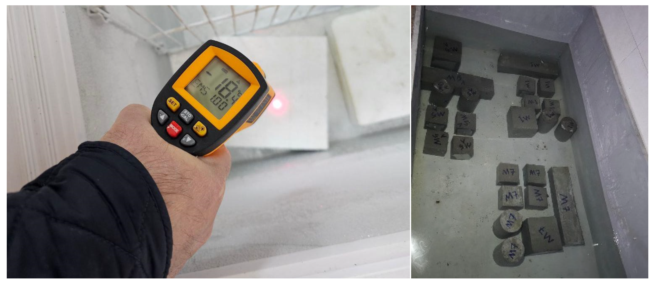
2.8. Freeze–Thaw (FT)

The samples’ durability was evaluated using a feasible and straightforward freeze–thaw method due to a lack of laboratory facilities. The concrete samples were water cured in the lab for 28 days. Their initial mass, UPV, and appearance were noted. For 12 h, the concrete samples were kept in a freezer at −18 °C. The samples were taken out of the freezer and allowed to defrost (thaw) by submerging them in water at ambient temperature, around 20 °C, for 12 h. For 15 cycles, this freeze (12 h) and thaw (12 h) cycle was performed; then a further 15 cycles of the freeze (24 h) and thaw (24 h) cycles were also performed. Therefore, a total of 30 freeze–thaw cycles were applied. Following the necessary number of cycles, the concrete samples’ conditions, such as surface scaling, cracking and deterioration, mass loss, and UPV, were evaluated before the compressive strength test was conducted (Figure 4).

3. Results and Discussion

3.1. Workability and Density

The concrete mixture’s workability and fluidity for compaction into the formwork with the least amount of external effort are usually assessed by the slump test. The slump readings of SS concrete mixtures fell between 40 and 90 mm. In general, when the amount of all three types of SS in concrete increases, the slump reduces. This is because the employed SS’s angularity and absorption capacity make the concrete mixture less flowable. However, the workability of concrete was more negatively impacted by LDSS and SSP; the dosage of SP for those concrete mixtures was raised from 0.5% to 0.75% because of their high angularity, porosity, and high absorption capacity. The results of published studies [31,32] showed that workability was adversely affected using steel slag at 50% replacement ratio and higher. The cement and SSP SEM images (Figure 3) suggest that the SSP may have more porosity because of trapped gas bubbles or voids from the steel production process’s rapid cooling. Under SEM (Figure 3), it is easier to see porous structures in SSP, which display irregular or hollow features that may not be as prevalent in cement particles. When discussing lowering dead loads to reduce portions of the structural elements for more cost-effective construction or lowering load on the formwork during casting, density is an important factor. As is typically the case, the trend of density almost directly influences the trend of compressive strength. As illustrated in Figure 5, concrete’s density rises when its HDSS concentration rises by 40% [19,20,32]. This is explained by the fact that HDSS has a higher specific gravity than natural coarse aggregate. Structures like bases, retaining walls, earthwork blocks, sound barriers, and radiation shields can benefit from HDSS’s high density. Although the density of concrete is somewhat decreased by using LDSS, it is not different from normal concrete.

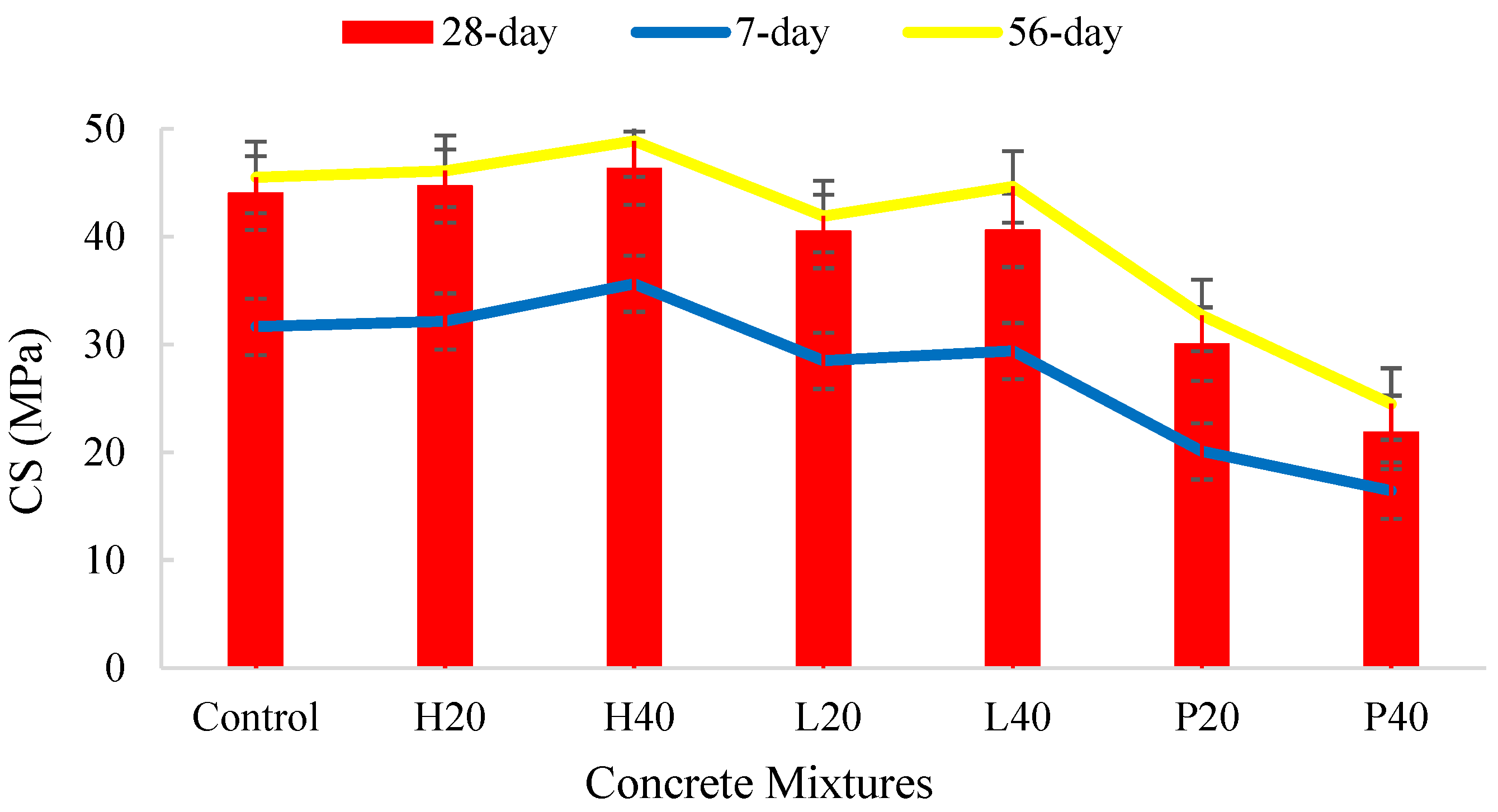
3.2. Compressive Strength (CS)

Figure 6 shows the effect of different types and replacement levels of SS on the compressive strength (CS) of concrete mixtures at different curing times. The net change in CS of mixtures containing varying dosages of SS at different ages compared with control mixture is shown in Figure 7. As the curing period increases, the CS of all mixes including SS increases as well. Concrete with 20% and 40% HDSS aggregate generated about 72% and 77% of its 28-day strength, respectively, according to the 7-day compressive strength values. Concrete with 20% and 40% LDSS aggregate developed nearly 70% and 72% of its corresponding 28-day strength. While the control mix in this study was 72%, normal concrete often reaches 70–80% of the 28-day strength in the first 7 days. The findings show which HDSS ratios at 20% and 40% increase the concrete’s CS during all curing periods [6,19,20]. After 28 days, the strength values of the two concrete mixtures mentioned above (H20 and H40) rose by 1.5% and 5.2%, respectively, compared with control concrete. The incorporation of HDSS increases the stiffness of concrete, which has a positive effect on CS. Even though the compressive strength decreased at all water curing periods when 20% and 40% of the natural coarse aggregate was replaced with LDSS, the mixtures containing LDSS still achieved a high strength of 40 MPa. The strength of the mixtures (L20 and L40) was found to have decreased after 28 days of age; the corresponding reduction values were 8.1% and 7.8%, respectively. The fact that the 20% and 40% LDSS concretes’ compressive strengths did not differ significantly was intriguing. HDSS increases the mechanical bond between the aggregate and the cement paste and creates a denser concrete mix because of its rough surface texture, high specific gravity, and density. Better bonding improves the concrete’s overall structural integrity, which raises its compressive strength. Despite having a more angular surface texture than HDSS, LDSS has a lower CS because of its higher-porosity nature and lower stiffness and hardness. The concretes with SSP (P20 and P40) showed the greatest decrease in compressive strength. For mixes containing 20% and 40% SSP, the reduction was 31.8% and 43.2%, respectively. Regarding the SSP, this type of SS produced in IF often has less reactive qualities than other types of slags because of its lower calcium content, which limits its hydraulic capabilities. As shown in Figure 7 and Figure 8, the concrete mixtures including SSP have the lowest CS when compared to the control mixture, which may limit its potential to contribute to the strength gain of the concrete. While the oxides in Type 1 Portland cement primarily form C3S, C2S, C3A, and C4AF, which give cement its primary strength and setting properties, the higher iron oxide (Fe2O3) and silica (SiO2) content of this type of SS powder gives it different hydraulic properties compared to Portland cement, and it has less calcium oxide (CaO), which is crucial for the early hydration and strength development in concrete (Table 1). SSP’s early activity is significantly lower than that of cement, and it can even lower the early hydration rate of Portland cement. Generally, IF-produced SS is less effective than other SS types and as a cement substitute because of its weaker reactivity, particularly in high-strength applications. Even if cementitious materials of C2S and C3S are offered in SS composition, SSP was unable to substitute Type 1 Portland cement in concrete mixtures, according to the strength data. This suggests that SS chemistry is not the sole criterion for evaluating hydraulic activity. Two physical factors of the formation temperature and the SS cooling rate have been reported in the literature to significantly weaken SS hydraulic activity [33].

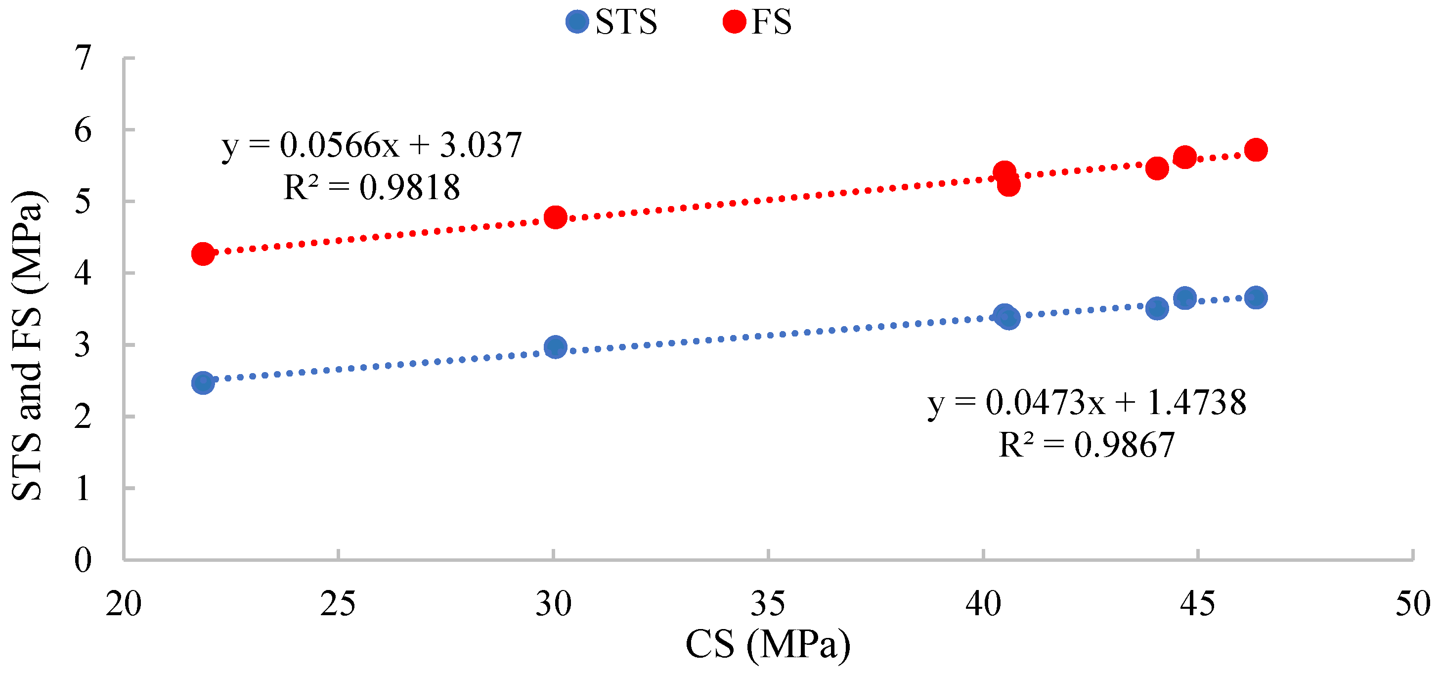
3.3. Splitting Tensile Strength (STS)

Figure 8 illustrates the impact of various SS types and dosages on STS (or modulus of rupture) as well as the net change in the STS of concrete mixtures when compared to the control mixture. This shows the typical outcomes of replacing SS in all proportions after 28 days of curing. The findings show that, as the percentage of HDSS replaced in concrete grows, so does the value of STS. Higher angularity SS aggregates in concrete produce greater strength, which activates the material combination and improves the interaction between the SS aggregate and the matrix [21]. This is because HDSS particles become active under tensile loading well before they break at peak load; as a result, the strong concrete matrix resists stretching action on the concrete. Furthermore, at 28 days, the substitution of natural coarse aggregate for LDSS shows a little drop in STS at both 20% and 40% replacement percentages when compared to the control concrete. Similar to the values for compressive strength, the mixtures that contained SSP had the lowest STS values when compared to the control mixture [20].
Figure 8. STS of concrete mixtures with their net change.
Buildings 15 01514 g008
The macrostructure analysis and failure details of a specimen’s two symmetrical pieces are displayed in Figure 9. The typical brittle failure typically associated with normal concrete was the mode of failure for the concrete specimens that contained SS aggregates and SSP. The rupture mechanism of the control and concretes that contained this type of slag differed. A portion of the natural coarse aggregate along the failure plane in the control concrete was found to be de-bonded from the matrix (as shown in Figure 9, a1 and a2: indicated by white circles). This suggests that the natural coarse aggregate’s failure strength is greater than the aggregate–matrix bond in that particular area. However, certain HDSS aggregates were observed to shear off along the failure plane (Figure 9, b1 and b2: indicated by red circles) in concrete. This suggests that the HDSS aggregate’s failure strength is lower than the bond between the aggregate and the matrix in that particular area. The concrete mixtures including LDSS aggregate (Figure 9, c1 and c2: shown by yellow circles) experienced the same failure mode. However, nearly all LDSS aggregates sheared off along the failure plane. The surface’s angularity and improved interlocking with the paste are the causes of this type of rupture. The same figure also shows the pores on the surface of LDSS aggregates. This demonstrates that conventional concrete and concrete containing slag made in IF have different under-loading rupture mechanisms. The rupture in concrete containing this type of slag not only happened in the mortar matrix/slag interfaces but also in the middle of slag aggregate, which creates the weak link of the concrete, especially in LDSS aggregates.

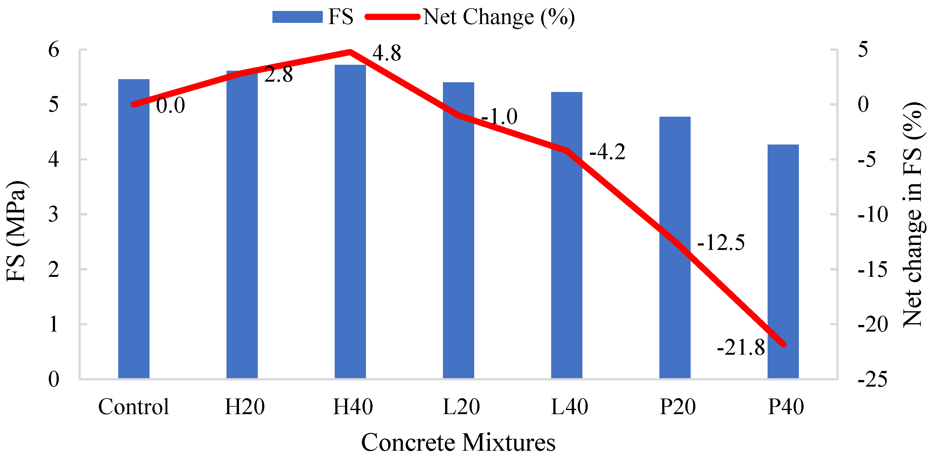
3.4. Flexural Strength (FS)

The effect of varying types and replacement percentages of SS on FS and net change in FS of concrete mixtures compared with the control is shown in Figure 10. The maximum and lowest values of FS are found for 40% HDSS and 40% SSP replacements, respectively. When HDSS is added to concrete, the FS increase. This could be because SS reinforces the concrete, improving its bond strength with the matrix [34,35,36,37]. Compared to the control concrete, the FS of mixtures containing LDSS is lower. There is a 2.7% increase by 20% HDSS, a 4.5% increase by 40% HDSS, a 1.1% drop by 20% LDSS, and a 4.2% decrease by 40% LDSS. Additionally, the drop in FS is greater than that of other concrete mixtures, at 12.4% and 21.8%, respectively, when 20% and 40% of SSP is replaced with cement. Based on the results, it can be concluded that the addition of HDSS and LDSS to the concrete led to an increase in the concrete’s toughness and a decrease in it, respectively [6,31,38]. The relationship between the compressive, flexural, and splitting tensile strengths of concrete mixtures with different types and quantities of SS aggregates is shown in Figure 11. Compressive strength rises in proportion to flexural and tensile strength. The relationship between concrete mixtures’ flexural, tensile, and compressive strengths appears to be better described by a linear function. With Y representing compressive strength (MPa) and X representing tensile and flexural strengths (MPa), it shows a very strong positive correlation.

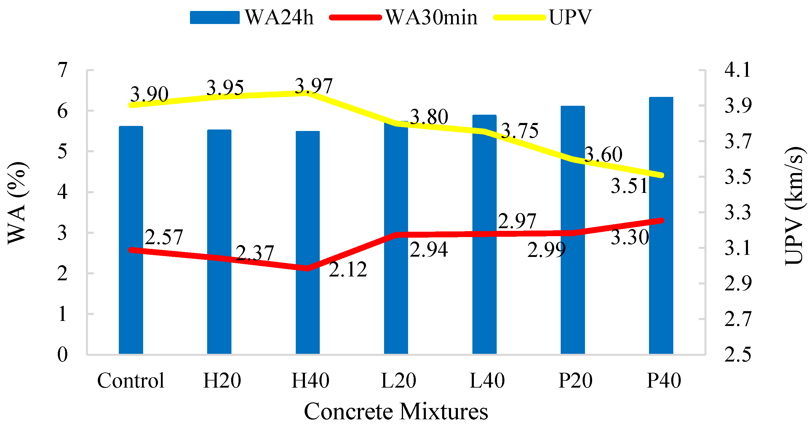
3.5. Ultrasonic Pulse Velocity (UPV)

The UPV values of concrete incorporating different types and amounts of SS aggregate at 28 days water curing is shown in Figure 12. Concrete uniformity, the existence of cracks or voids, changes in qualities over time, and dynamic physical attributes can all be determined using the UPV measurement as a non-destructive technique of testing [34]. The tendency is similar to that of compressive strength, in that UPV values rise with an increase in HDSS aggregate in concrete and fall with an increase in LDSS and SSP content. The range of the UPV readings was 3.51 to 3.97 km/s. Concrete with UPV values between 3.5 and 4.5 km/s is regarded as “good” quality, according to [39]. Based on the UPV data showing decreased porosity and better dense and appropriate compaction, practically all concrete mixtures in the current study with a UPV of greater than 3.5 km/s can be regarded as concretes in “good condition”. Concrete undergoes physical–chemical changes over time because of hydration reactions, which gradually boost the material’s density and strength and facilitate the ultrasonic wave’s propagation [40].

3.6. Water Absorption (WA)

Figure 12 illustrates how various SS types and substitutions affect each mix’s initial (30 min) WA capacity as well as its total capacity (24 h). Concrete mixtures’ WA is a crucial characteristic since it indicates their porosity and permeability, which can affect their performance, durability, and longevity. In general, high porosity is indicated by high WA. Because HDSS is hard and dense, it lessens the development of capillary holes and micro-voids in the concrete matrix. By doing this, the concrete’s overall porosity is reduced, which results in a marginally better WA and, ultimately, increased strength and durability as compared to other concrete mixtures. The control and HDSS aggregate-containing concrete did not, however, differ significantly. At 30 min, the WA of every concrete mix ranged from 2.12% to 3.0%. While the concrete with a larger volume of LDSS aggregate demonstrated higher absorption, the overall WA ranged from 5.47% to 6.20%. Concrete mixtures with initial and total WA show moderate porosity and are appropriate for moderate environmental conditions. Figure 12 also illustrates the relationship between initial and total WA, and the UPV of concrete with different amounts of SS aggregates. An increase in UPV results in a decrease in WA.

3.7. Freeze–Thaw (FT)

The effect of freeze–thaw (FT) cycles on the UPV and compressive strength (CS) of concrete mixtures containing different types and replacements of SS is shown in Figure 13. Visual inspection revealed that the specimens’ surfaces were complete and smooth both before and after testing with thick cement slurry wrapping around the outside, and there was no surface scaling, cracking, or deterioration. Therefore, there was no mass loss. However, the UPV values and compressive strength of concrete specimens decreased after FT cycles. It was found that the concrete containing SS was more seriously affected when compared with the control concrete. The decrease percentage in compressive strength for concrete containing HDSS was 8.95–12.62%, for LDSS it was 12.47–21.31%, and for SSP it was 15.64–21.74%. This resulted from the repetitive FT of water in the concrete capillaries, which caused cracks to continuously extend and expand before eventually penetrating one another. Simultaneously, the fully closed microbubbles started to crack due to frost heave as a result of the stresses of hydrostatic pressure and expansion pressure. This phenomenon occurred in LDSS concretes at a higher rate than in the HDSS and control concretes. Similar results have been reported by other studies. It is advised that a small proportion of air-entraining admixtures and/or surface treatment can keep this strength decline within tolerable bounds. [2,20,22]. The higher WA (Table 1) of SS aggregates allow more water to seep into the concrete. Internal pressure results from this trapped water expanding by nearly 10% as temperatures fall below freezing. This pressure causes breaking after several cycles. Regarding SSP, it is less reactive than cement with high CaO content and does not favourably modify the pore structure, which results in weaker matrix–aggregate interfaces and interfacial transition zone (ITZ) that are more vulnerable to microcracking during freeze–thaw cycles. The concrete’s initial resistance to freeze–thaw cycles can be decreased by the expansive behaviour of this form of SS, which still contains high Fe oxides (Table 1) and free MgO that hydrate and expand slowly [20,21,22].

4. Conclusions

Steel slag, which is still a waste rather than a by-product in many parts of the globe, including Iraq and the Kurdistan region, can be advantageous to many civil engineering applications in terms of the economy and the environment. This study of the impact of various SS types and doses on the engineering performance of concrete yielded important conclusions, including the following:
  • Using LDSS and SSP replacement reduced workability more than replacing HDSS in the concrete mixture; this could be because LDSS’s porose structure and angularity absorb more water than natural coarse aggregate, but this issue is easily resolved with superplasticizer.
  • The high density of concrete with high amounts of SS is an advantage for structures such as retaining walls, bases, earthwork blocks, sound insulation, and radiation shields.
  • The use of HDSS in concrete resulted in an increase in the mechanical properties. At 20% and 40%, the value of compressive strength was improved by 1.5% and 5.2%, respectively. The trend is similar for other mechanical properties.
  • The use of LDSS and SSP in concrete mixtures resulted a decrease in the durability and mechanical performance. At 20% and 40% LDSS, the value of compressive strength was decreased by 8.1% and 7.8%, respectively. The trend is similar for other mechanical and durability properties.
  • Due to the very low reactivity of this type of slag, SSP is not recommended to be used in concrete production as a cement replacement material.
  • Compared to the control concrete, the freeze–thaw cycles reduced the UPV and compressive strength of concrete with varying types and amounts of SS. The durability is slightly compromised and can be considered lower in all mixes containing SS.
  • Using 40% HDSS substitution in concrete led to the best results when the mechanical and durability characteristics of the current investigation were considered. Nonetheless, depending on the application, an acceptable strength for various types and replacement levels can be attained with the appropriate mix design.
Studying the microstructure of the slag–matrix bond is an important recommendation for future research on this new type of steel slag.

Author Contributions

Conceptualization, methodology, investigation, formal analysis, writing—original draft preparation, writing and editing, visualization, supervision, B.M.A.H.; resources, review, funding acquisition, and project administration, A.I.A., Y.S.S. and K.M.O. All authors have read and agreed to the published version of the manuscript.

Funding

This research received no external funding.

Data Availability Statement

The datasets used and/or analysed during the present study are available from the corresponding author on reasonable request.

Acknowledgments

The authors express their great gratitude to Darin Steel for their assistance, support, and materials supply. This research was financially supported by Darin Steel, and the corresponding author served as a supervisor for conducting this research at Darin Steel. The authors would like to thank Soran University—Civil and Environmental Engineering Department and Erbil Polytechnic University—College of Technology for their help and laboratory facilities. We appreciate the lab assistance of Amin Qader, Samir Mahdi and Danar Mirza.

Conflicts of Interest

Authors Ali Ibrahim Ali, Yousif Sadiq Smail and Karwan Maroof Omer were employed by the company Darin Steel Factory. The remaining author declares that the research was conducted in the absence of any commercial or financial relationships that could be construed as a potential conflict of interest. The authors declare that this study received funding from Darin Steel. The funder was not involved in the study design, collection, analysis, interpretation of data, the writing of this article or the decision to submit it for publication.

Nomenclature

CSCompressive Strength
FSFlexural Strength
FTFreeze–Thaw
HDSSHigh-Density Steel Slag
IFInduction Furnace
LDSSLow-Density Steel Slag
SEMScanning Electron Microscopy
SPSuperplasticiser
SSSteel Slag
SSPSteel Slag Powder
STSSplitting Tensile Strength
UPVUltrasonic Pulse Velocity
WAWater Absorption

References

  1. Li, J.; Pan, S.Y.; Kim, H.; Linn, J.H.; Chiang, P.C. Building green supply chains in eco-industrial parks towards a green economy: Barriers and strategies. J. Environ. Manag. 2015, 162, 158–170. [Google Scholar] [CrossRef] [PubMed]
  2. Gencel, O.; Karadag, O.; Oren, O.H.; Bilir, T. Steel slag and its applications in cement and concrete technology: A review. Constr. Build. Mater. 2021, 283, 122783. [Google Scholar] [CrossRef]
  3. Baban, M. Climate Change in Iraq and the Kurdistan Region: Consequences of Increased Oil, Electricity, Cement, and Iron Production on Water. Rudaw Research Centre. 2023. Available online: https://rudawrc.net/en/pdf/article/climate-change-in-iraq-and-the-kurdistan-region-consequences-of-increased-oil-electricity-cement-and-iron-production-on-water-2023-10-18 (accessed on 20 March 2025).
  4. Guo, J.; Bao, Y.; Wang, M. Steel slag in China: Treatment, recycling, and management. Waste Manag. 2018, 78, 318–330. [Google Scholar] [CrossRef]
  5. Üksel, İ. A review of steel slag usage in construction industry for sustainable development. Environ. Dev. Sustain. 2017, 19, 369–384. [Google Scholar] [CrossRef]
  6. Wang, Q.; Yan, P.; Yang, J.; Zhang, B. Influence of steel slag on mechanical properties and durability of concrete. Constr. Build. Mater. 2013, 47, 1414–1420. [Google Scholar] [CrossRef]
  7. Wang, Q.; Yang, J.W.; Yan, P.Y. Influence of initial alkalinity on the hydration of steel slag. Sci. China Technol. Sci. 2012, 55, 3378–3387. [Google Scholar] [CrossRef]
  8. Dhoble, Y.N.; Ahmed, S. Review on the innovative uses of steel slag for waste minimization. J. Mater. Cycles Waste Manag. 2018, 20, 1373–1382. [Google Scholar] [CrossRef]
  9. Reddy, A.S.; Pradhan, R.K.; Chandra, S. Utilization of basic oxygen furnace (BOF) slag in the production of a hydraulic cement binder. Int. J. Miner. Process. 2006, 79, 98–105. [Google Scholar] [CrossRef]
  10. Mayes, W.M.; Younger, P.L.; Aumônier, J. Hydrogeochemistry of alkaline steel slag leachates in the UK. Water Air Soil Pollut. 2008, 195, 35–50. [Google Scholar] [CrossRef]
  11. Shi, C.; Qian, J. High performance cementing materials from industrial slags—A review. Resour. Conserv. Recycl. 2000, 29, 195–207. [Google Scholar] [CrossRef]
  12. Zhang, T.; Yu, Q.; Wei, J.; Li, J.; Zhang, P. Preparation of high performance blended cements and reclamation of iron concentrate from basic oxygen furnace steel slag. Resour. Conserv. Recycl. 2011, 56, 48–55. [Google Scholar] [CrossRef]
  13. Jiang, Y.; Ling, T.-C.; Shi, C.; Pan, S.-Y. Characteristics of steel slags and their use in cement and concrete—A review. Resour. Conserv. Recycl. 2018, 136, 187–197. [Google Scholar] [CrossRef]
  14. Netinger, I.; Bjegović, D.; Vrhovac, G. Utilisation of steel slag as an aggregate in concrete. Mater. Struct. 2011, 44, 1565–1575. [Google Scholar] [CrossRef]
  15. Kalpavalli, A.; Naik, S.M. Use of demolished concrete wastes as coarse aggregates in high strength concrete production. Int. J. Eng. Res. Technol. 2015, 4, 1040–1045. [Google Scholar] [CrossRef]
  16. Liu, X.; Liu, X.; Zhang, Z.; Ai, X. Effect of carbonation curing on the characterization and properties of steel slag-based cementitious materials. Cem. Concr. Compos. 2024, 154, 105769. [Google Scholar] [CrossRef]
  17. Ilyushechkin, A.Y.; Roberts, D.G.; French, D.; Harris, D.J. IGCC Solids Disposal and Utilisation; Final Report for ANLEC Project 5-0710-0065; CSIRO: Canberra, Australia, 2012. [Google Scholar]
  18. Yi, H.; Xu, G.; Cheng, H.; Wang, J.; Wan, Y.; Chen, H. An overview of utilization of steel slag. Procedia Environ. Sci. 2012, 16, 791–801. [Google Scholar] [CrossRef]
  19. Mitwally, M.E.; Elnemr, A.; Shash, A.; Babiker, A. Utilization of steel slag as partial replacement for coarse aggregate in concrete. Innov. Infrastruct. Solut. 2024, 9, 175. [Google Scholar] [CrossRef]
  20. Maslehuddin, M.; Sharif, A.M.; Shameem, M.; Ibrahim, M.; Barry, M.S. Comparison of properties of steel slag and crushed limestone aggregate concretes. Constr. Build. Mater. 2003, 17, 105–112. [Google Scholar] [CrossRef]
  21. Pellegrino, C.; Gaddo, V. Mechanical and durability characteristics of concrete containing EAF slag as aggregate. Cem. Concr. Compos. 2009, 31, 663–671. [Google Scholar] [CrossRef]
  22. Qasrawi, H. The use of steel slag aggregate to enhance the mechanical properties of recycled aggregate concrete and retain the environment. Constr. Build. Mater. 2014, 54, 298–304. [Google Scholar] [CrossRef]
  23. Manso, J.M.; Polanco, J.A.; Losañez, M.; González, J.J. Durability of concrete made with EAF slag as aggregate. Cem. Concr. Compos. 2006, 28, 528–534. [Google Scholar] [CrossRef]
  24. Sharba, A.A. The Efficiency of Steel Slag and Recycled Concrete Aggregate on the Strength Properties of Concrete. KSCE J. Civ. Eng. 2019, 23, 4846–4851. [Google Scholar] [CrossRef]
  25. Sabapathy, Y.K.; Balasubramanian, V.B.; Shiva Shankari, N.; Yeshwant Kumar, A.; Ravichandar, D. Experimental investigation of surface-modified EOF steel slag as coarse aggregate in concrete. J. King Saud. Univ. Eng. Sci. 2017, 29, 388–393. [Google Scholar] [CrossRef]
  26. Herki, B.M.A. Environmental Hazards in the Kurdistan Region–Iraq. Rudaw Research Centre. 2022. Available online: https://rudawrc.net/sorani/article/metrsyie-jingeyiekan-le-heremi-kwrdstan (accessed on 20 March 2025).
  27. Herki, B.M.A. Strength and Absorption Study on Eco-Efficient Concrete Using Recycled Powders as Mineral Admixtures under Various Curing Conditions. Recycling 2024, 9, 99. [Google Scholar] [CrossRef]
  28. Herki, B.M.A.; Khatib, J.M.; Hamadamin, M.N.; Kareem, F.A. Sustainable Concrete in the Construction Industry of Kurdistan-Iraq through Self-Curing. Buildings 2022, 12, 1318. [Google Scholar] [CrossRef]
  29. Herki, B.M.A. Combined Effects of Densified Polystyrene and Unprocessed Fly Ash on Concrete Engineering Properties. Buildings 2017, 7, 77. [Google Scholar] [CrossRef]
  30. Herki, B.M.A. Absorption Characteristics of Lightweight Concrete Containing Densified Polystyrene. Civ. Eng. J. 2017, 3, 594–609. [Google Scholar] [CrossRef]
  31. Qasrawi, H.; Shalabi, F.; Asi, I. Use of low CaO unprocessed steel slag in concrete as fine aggregate. Constr. Build. Mater. 2009, 23, 1118–1125. [Google Scholar] [CrossRef]
  32. Yu, X.; Tao, Z.; Song, T.-Y.; Pan, Z. Performance of concrete made with steel slag and waste glass. Constr. Build. Mater. 2016, 114, 737–746. [Google Scholar] [CrossRef]
  33. Azeez, A.; Hassan, M.; Atiyah, A. Evaluation of the Performance of Steel Slag and Waste Glass as a Cement Replacement. Eng. Technol. J. 2023, 41, 1567–1577. [Google Scholar] [CrossRef]
  34. Ravikumar, H.; Dattatreya, J.K.; Shivananda, K.P. Experimental Investigation on Replacement of Steel Slag as Coarse Aggregate in Concrete. J. Civ. Eng. Environ. Technol. 2015, 2, 58–63. [Google Scholar]
  35. Alizadeh, R.; Chini, M.; Ghods, P.; Hoseini, M.; Montazer, S.; Shekarchi, M. Utilization of Electric Arc Furnace Slag as Aggregates in Concrete-Environmental Issue. In Proceedings of the 6th CANMET/ACI International Conference on Recent Advances in Concrete Technology, Bucharest, Romania, 8–11 June 2003; pp. 451–464. [Google Scholar]
  36. Li, Y.; Liu, F.; Yu, F.; Du, T. A review of the application of steel slag in concrete. Structures 2024, 63, 106352. [Google Scholar] [CrossRef]
  37. Neville, A.M.; Brooks, J.J. Concrete Technology; Pearson Education Limited: Harlow, UK, 2004. [Google Scholar]
  38. Lang Pang, L.; Liao, S.; Wang, D.; An, M. Influence of steel slag fineness on the hydration of cement-steel slag composite pastes. J. Build. Eng. 2022, 57, 104866. [Google Scholar] [CrossRef]
  39. Yew, M.K.; Mahmud, H.B.; Ang, B.C.; Yew, M.C. Effects of heat treatment on oil palm shell coarse aggregates for high strength lightweight concrete. Mater. Des. (1980–2015) 2014, 54, 702–707. [Google Scholar] [CrossRef]
  40. Albano, C.; Camacho, N.; Hernández, M.; Matheus, A.; Gutiérrez, A. Influence of content and particle size of waste pet bottles on concrete behaviour at different w/c ratios. Waste Manag. 2009, 29, 2707–2716. [Google Scholar] [CrossRef]
Figure 1. Induction furnace SS lumps.
Buildings 15 01514 g001
Figure 2. (a) HDSS and (b) LDSS.
Buildings 15 01514 g002
Figure 3. (a) SSP (light black-top) and cement (grey-bottom), (b) SEM of cement, and (c) SEM of SSP.
Buildings 15 01514 g003
Figure 4. Freeze–thaw test.
Buildings 15 01514 g004
Figure 5. Density of concrete mixtures.
Buildings 15 01514 g005
Figure 6. CS of concrete mixtures at varying curing times.
Buildings 15 01514 g006
Figure 7. Net change in CS of concrete mixtures at different curing times.
Buildings 15 01514 g007
Figure 9. Macrostructure of control, HDSS and LDSS concrete samples.
Buildings 15 01514 g009
Figure 10. FS of concrete mixtures with their net change.
Buildings 15 01514 g010
Figure 11. Correlation between CS and FS and STS of concrete mixtures.
Buildings 15 01514 g011
Figure 12. UPV, total and initial WA of concrete mixtures and their relationship.
Buildings 15 01514 g012
Figure 13. UPV and CS of concrete mixtures before and after freeze–thaw cycles.
Buildings 15 01514 g013
Table 1. Chemical and physical properties of cement and SS.
ConstituentComposition (%)Designation (SS)Property
CementSSShapeHDSSHighly angular
SiO219.8338.73LDSSHighly angular and porosity
Fe2O32.3225.87Surface textureRough
CaO61.6615.61ColourLight black
Al2O34.489.84Combustibility Non-combustible
MgO3.145.21
MnO0.312.10Specific GravityHDSS3.1
K2O0.680.83LDSS2.7
TiO20.320.51Water Absorption (%)HDSS3.3
Other7.261.3LDSS3.9
Table 2. Mix proportions.
MixMix CodeCement (kg/m3)FA (kg/m3)CA (kg/m3)SS (%)SS TypeWater (kg/m3)SP (%)
1Control40080012000-2000.5
2H2040080096020HDSS2000.5
3H4040080072040HDSS2000.5
4L2040080096020LDSS2000.5
5L4040080072040LDSS2000.75
6P20320800120020SSP2000.75
7P40240800120040SSP2000.75
FA: fine aggregate; CA: coarse aggregate; SS: steel slag; HDSS: high-density steel slag; LDSS: low-density steel slag; SSP: steel slag powder; SP: superplasticiser.
Disclaimer/Publisher’s Note: The statements, opinions and data contained in all publications are solely those of the individual author(s) and contributor(s) and not of MDPI and/or the editor(s). MDPI and/or the editor(s) disclaim responsibility for any injury to people or property resulting from any ideas, methods, instructions or products referred to in the content.

