Article

Dynamic Characteristics Analysis of Three-Layer Steel–Concrete Composite Beams

1
Beijing Urban Construction Group Co., Ltd., Beijing 100088, China
2
Department of Hydraulic Engineering, Tsinghua University, Beijing 100084, China
3
Research Institute of Highway, Ministry of Transport, Beijing 100088, China
4
School of Civil Engineering, Beijing Jiaotong University, Beijing 100044, China
5
CCCC Road and Bridge Construction Co., Ltd., Gen Contracting Branch, Beijing 100012, China
6
Beijing Urban Construction Design & Development Group Co., Ltd., Beijing 100045, China
*
Author to whom correspondence should be addressed.
Buildings 2025, 15(8), 1347; https://doi.org/10.3390/buildings15081347
Submission received: 25 March 2025 / Revised: 10 April 2025 / Accepted: 15 April 2025 / Published: 17 April 2025
(This article belongs to the Special Issue Advances in Steel and Composite Structures)

Abstract

The dynamic behavior of three-layer composite beams, consisting of concrete slabs and steel beams, is influenced by the structural configuration of each layer as well as the shear connectors. The interlayer shear stiffness in three-layer composite beams governs their global dynamic behavior, while interlayer slippage-induced localized vibration effects represent a key limiting factor in practical applications. Based on the dynamic test results of steel–concrete double-layer composite beams, the feasibility of a finite element solid model for composite beams, which accounts for interlayer shear connectors and beam body characteristics, has been validated. Utilizing identical modeling parameters, an analytical model for the inherent vibration characteristics of three-layer steel–concrete composite beams has been developed. This study encompasses two types of composite beams: concrete–steel–concrete (CSC) and concrete–concrete–steel (CCS). Numerical simulations and theoretical analysis systematically investigated the effects of interface shear connector arrangements and structural geometric parameters on dynamic performance. Research indicates that the natural frequency of steel–concrete three-layer composite beams exhibits a distinct two-stage increasing trend with the enhancement in interlayer shear stiffness. For CSC-type simply supported composite beams, the fundamental vertical vibration frequency increases by 37.82% when achieving full shear connection at both interfaces compared to the unconnected state, while two-equal-span continuous beams show a 38.06% improvement. However, significant differences remain between the fully shear-connected state and theoretical rigid-bonding condition, with frequency discrepancies of 24.69% for simply supported beams and 24.07% for continuous beams. Notably, CCS-type simply supported beams display a 12.07% frequency increase with full concrete-to-concrete connection, exceeding even the theoretical rigid-bonding frequency value. Longitudinal connector arrangement non-uniformity significantly impacts dynamic characteristics, while the transverse arrangement has minimal influence. Among structural parameters, steel flange plate thickness has the most significant effect, followed by concrete slab width and thickness, with steel web thickness having the least impact. Based on the observation that the first-order vertical vibration frequency of three-layer composite beams exhibits a two-stage decreasing trend with an increase in the span-to-depth ratio, it is recommended that the span-to-depth ratio of three-layer steel–concrete composite beams should not be less than 10.

1. Introduction

To fully exploit the material properties of constituent materials, multi-layer structural systems incorporate different materials in specific configurations to form composite systems that achieve enhanced performance characteristics compared to conventional single-material structures while optimizing construction efficiency [1,2,3,4]. These engineered systems find extensive applications across diverse engineering disciplines including advanced composite materials [5,6], laminated plate structures [2,7,8], high-rise building systems, and pavement engineering applications. The pioneering three-layer composite bridge, Spain’s Ciérvana Bridge constructed in 1978 [9,10], established the technical precedent for concrete–steel–concrete configurations typically formed through the addition of a concrete slab to the tension zone of conventional steel–concrete composite beams [11,12,13]. This innovative design approach can be selectively implemented in negative bending moment regions or extended throughout the entire bridge superstructure. Recent advancements in engineering technology have led to the development and implementation of various multi-layer composite beam configurations in modern bridge engineering, including corrugated steel web–concrete composite beams [14], steel truss web–concrete composite beams [15], concrete-filled steel tube–steel truss/corrugated steel web composite systems, and steel–concrete–steel sandwich beams [16,17]. In high-speed railway bridge applications, the ballastless track slab has been successfully integrated as a structural load-bearing component, creating an interdependent multi-layer system comprising the bridge deck, track slab, and rail components [18,19].
The dynamic analysis of three-layer composite beams has been performed through various theoretical and experimental approaches. Iurlaro et al. [20] conducted comprehensive free vibration experiments on aluminum–polyimide-foam-laminated beams, employing advanced signal processing techniques on excitation force and acceleration data to determine natural frequencies and corresponding mode shapes. Their comparative study of numerical models based on Timoshenko beam theory with shear correction coefficients versus refined zig-zag theory demonstrated the superior predictive accuracy of the latter approach for dynamic behavior. He et al. [21] developed an advanced dynamic analysis model incorporating Reddy’s modified higher-order shear deformation theory with partial interaction effects, which showed significant improvements in accuracy over conventional Timoshenko beam models. Hu et al. [22] formulated an innovative zig-zag theoretical model for the free vibration analysis of corrugated steel web composite beams using the variational principle of mixed energy, successfully satisfying zero-shear-stress boundary conditions at layer interfaces while eliminating the need for empirical shear correction coefficients.
As a critical performance indicator for structural systems, dynamic characteristics provide fundamental data for seismic performance evaluation and vehicle–bridge interaction analysis. However, current research exhibits a notable scarcity of both experimental investigations and theoretical developments specifically addressing the dynamic performance of three-layer composite beam systems. This knowledge gap underscores the necessity for comprehensive dynamic analyses of various composite beam configurations to identify and quantify key performance-influencing factors for engineering design optimization. Building upon established dynamic test data from steel–concrete double-layer composite beams, the present study validates an advanced finite element modeling approach that accurately incorporates interlayer shear connector behavior and composite beam characteristics. Using rigorously controlled modeling parameters, this research develops an analytical framework for investigating the inherent vibration properties in three-layer steel–concrete composite beams, with a particular focus on concrete–steel–concrete (CSC) and concrete–concrete–steel (CCS) configurations. Through systematic numerical simulations and theoretical analyses, this study quantitatively examines the influence of critical design parameters including interface shear connector arrangements and structural geometric properties on the dynamic performance characteristics of three-layer composite beam systems.

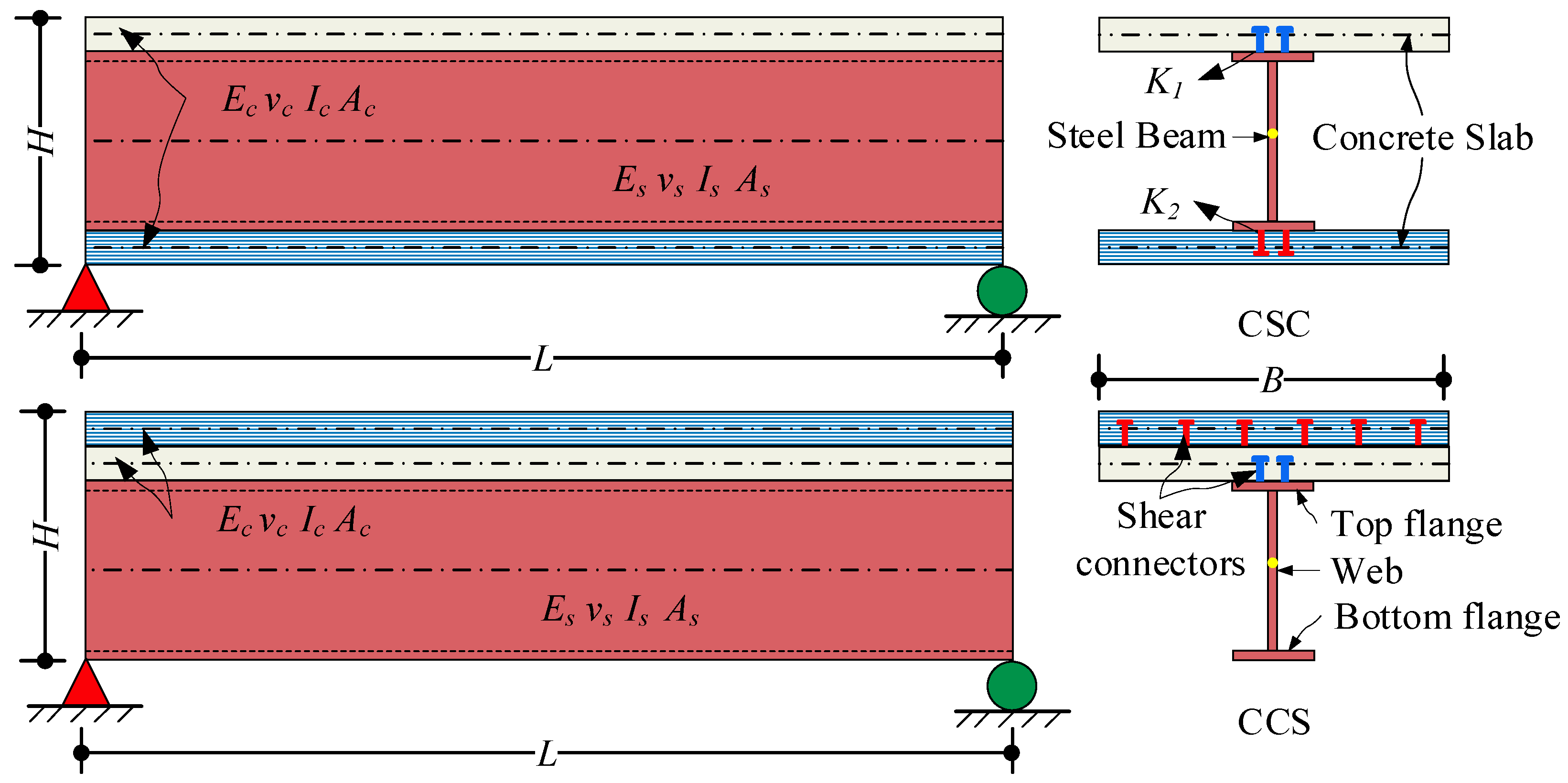
2. Structural Configuration of Three-Layer Steel–Concrete Composite Beams

The structural configuration of three-layer composite beams has evolved from traditional double-layer composite beams, comprising upper, middle, and lower layers. Each layer can be constructed using different material types and cross-sectional forms, integrated into a unified structure through shear connectors or binders at the interlayer interfaces. The shear connectors at these interfaces may exhibit identical or varying shear stiffness. Currently, the three-layer composite beam configurations with significant engineering practicality primarily include concrete–steel–concrete (CSC) and concrete–concrete–steel (CCS) composite beams. The CSC beams leverage the superior compressive strength of concrete to effectively address stress issues in the negative moment regions of continuous beams. In contrast, CCS beams are typically reinforced and modified by adding an additional concrete layer to traditional double-layer composite beams. The three-layer composite beam structure is shown in Figure 1.

3. Formulation and Validation of the Dynamic Analytical Model for Composite Beams

3.1. Dynamic Testing of Steel–Concrete Double-Layer Composite Beams
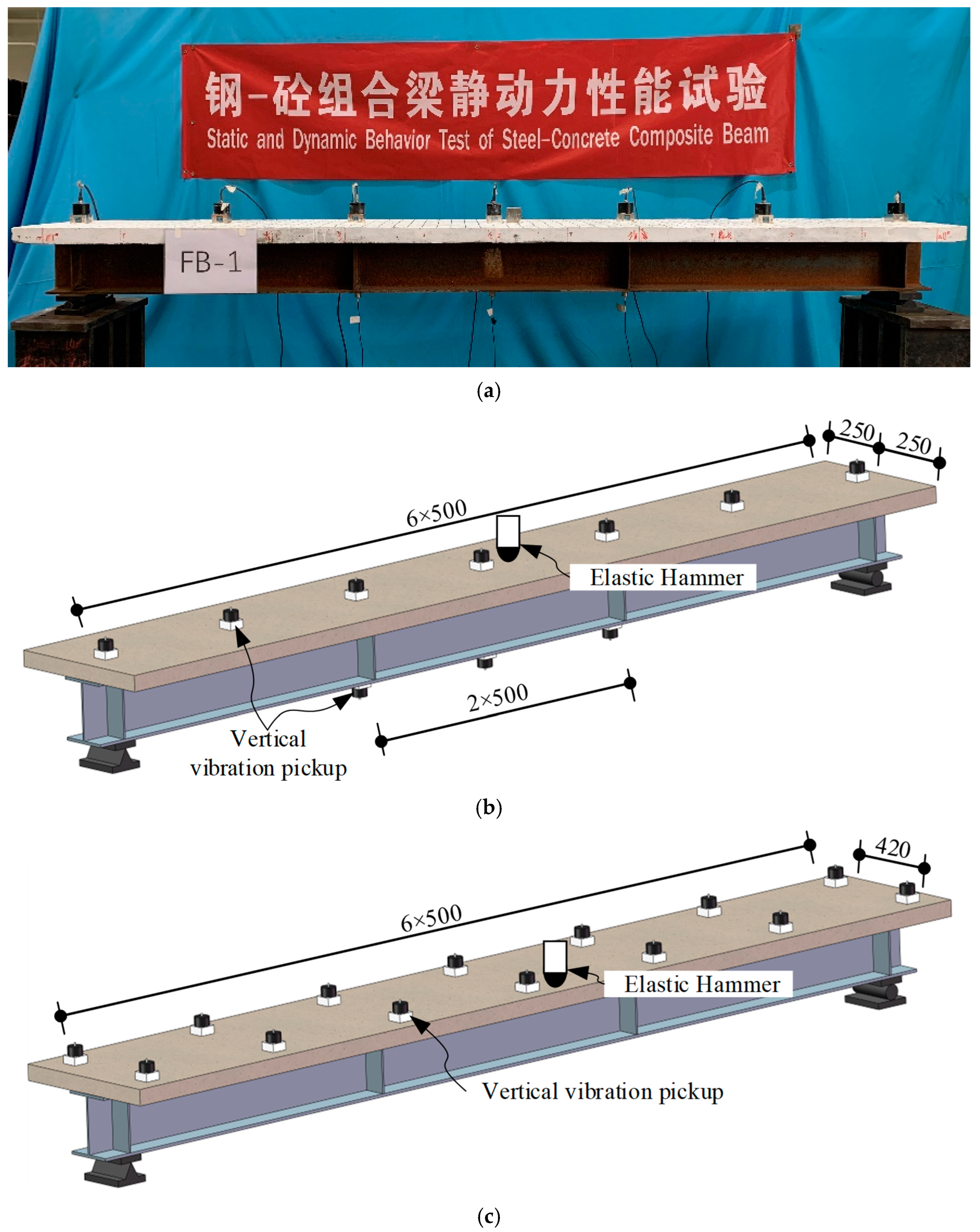
3.1.1. Test Design

The shear connector bears the function of connecting each layer of the steel–concrete composite beam, and its shear stiffness has a significant impact on the natural vibration characteristics of the composite beam. Therefore, three simply supported test beams with different connection degrees and 3.2 m in length are designed.
The nominal strength of concrete is 50 MPa. The steel beam adopts the HM 200 × 150 × 6 × 9 hot-rolled H-beam. The yield strength and the tensile strength of the steel are 323 MPa and 461 MPa, respectively, and the elongation is 22%. The elastic moduli of concrete and steel are E c = 34,500   M P a and E S = 206,000   M P a , respectively, and the Poisson’s coefficients are ν c = 0.2 and ν s = 0.3. The composite beam adopts double-row studs with a diameter of 10 mm and a height of 30 mm. The yield strength of the studs is 240 MPa, and the tensile strength is 400 MPa. The specific parameters of the test beam structure are shown in Table 1, where the shear connection degree is the ratio of the shear force of the interface under the limit equilibrium condition to the shear capacity of the shear connectors. It should be noted that during the fabrication of the test beam, the interface between the concrete slab and the steel beam is greased and separated by plastic film to ensure that the concrete slab and the steel beam are only connected by stud connectors.

3.1.2. Test Scheme

The influence of the degree of shear connection on the natural vibration characteristics of composite beams was investigated through the experimental testing of the natural vibration frequency and mode shapes of the test beams using the hammering test method. In this study, a 941B vertical vibration sensor from the China Orient Institute of Noise & Vibration (COINV) was employed as the vertical acceleration measurement device, while a 16-channel (3018C) data acquisition system from the COINV was utilized for acceleration data collection. A small DFC impact hammer was used as the excitation source. The setup of the hammering test is illustrated in Figure 2.
During the test, an elastic hammer was used to impact the test beam at one-third of its span (each position was struck twice to minimize experimental errors), thereby exciting the vibration of the beam. The vertical bending vibration and torsional vibration signals of the test beam were captured using a vibration sensor and a data acquisition system. The arrangement of the vibration sensor for the vertical bending and torsional vibration tests is illustrated in Figure 2b and Figure 2c, respectively.

3.1.3. Test Result

Experimental investigations revealed that when the longitudinal position of the excitation source is fixed at one-third of the span, the natural frequency of the beam exhibits low sensitivity to variations in the lateral impact position. Table 2 summarizes the natural vibration characteristics of three composite beams with different degrees of shear connection. As the degree of shear connection decreases, the natural frequency of the beam decreases significantly, indicating a corresponding reduction in the structural integrity of the composite beam.

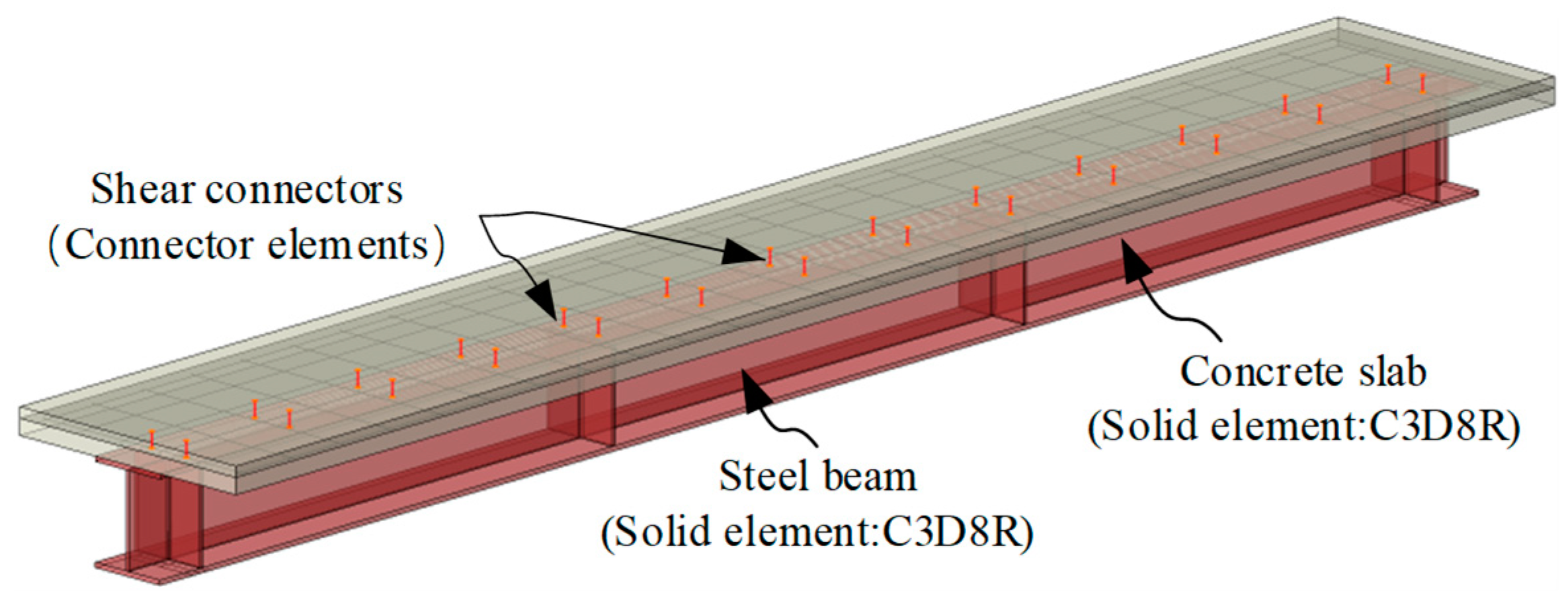
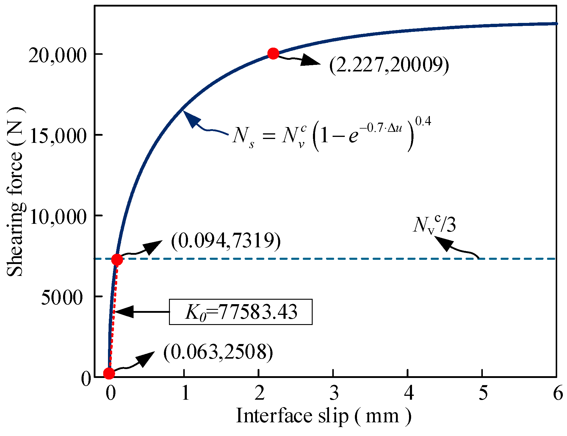
3.2. Establishment and Validation of a Dynamic Analysis Model for Steel–Concrete Composite Beams

To facilitate large-scale natural frequency calculations of composite beams, this study developed a dynamic finite element (FE) model of experimental double-layer composite beams using Abaqus/CAE 2022 FE analysis software to validate the feasibility of the modeling approach. In the modeling process, the concrete slab and steel beam were discretized using C3D8R solid elements, while the internal reinforcement was simulated with T3D2 truss elements. Shear connectors were modeled using connector elements, with the shear–slip constitutive relationship of the stud connectors characterized by the constitutive model proposed by Gattesco N [23] and Ollgaard [24], as defined in Equation (1). The design shear capacity (Nvc) of individual studs was calculated in accordance with Clause 3.1.14 of the China Code JGJ 138-2016 [25], as expressed in Equation (2).
V s = N v c 1 e β Δ u α
where, V s : shear force acting on the stud (N); N v c : design shear capacity of a single stud (N); Δ u : slip at the steel–concrete interface (mm); α, β: calculation parameters, assigned values of 0.40 and 0.70, respectively.
N v c = 0.43 A s E c f c 0.7 A s f a t
where, E c : elastic modulus of concrete (MPa); f c : axial compressive strength of concrete (MPa); A s : cross-sectional area of the stud shank (mm2); f a t : design value of ultimate tensile strength for headed studs (MPa).
Based on the stud layout of the experimental beams, connector spring elements were precisely arranged in the solid model of the composite beam. The spring element length was determined according to the actual stud dimensions, with the upper and lower ends rigidly bonded to the concrete slab and steel beam, respectively. The bonding influence radius was set as equal to the stud cross-sectional radius. The finite element (FE) model of the double-layer composite test beam is illustrated in Figure 3.
Following the aforementioned modeling parameters, solid FE models of three test beams were established. For composite beams with different shear connection degrees, the shear force of studs under self-weight loading was calculated and substituted into the stud constitutive Equation (1) to determine the stud slip and the tangent slope of the constitutive curve. This slope was adopted as the stud shear stiffness for subsequent analyses. The calculation of interfacial shear stiffness for the experimental double-layer composite beam is illustrated in Figure 4. The meshing strategy for the numerical model was optimized by implementing a 10 mm element size for concrete slab discretization and a finer 2 mm mesh for steel beam members, achieving an optimal balance between the computational cost, solution precision, and geometric representation of structural components.
The vertical and torsional vibration frequencies of the double-layer composite beams were computed using the dynamic FE model, and the results were compared with experimental data. The corresponding error analysis is presented in Table 3. The comparative study confirms the accuracy and reliability of the developed FE model for double-layer composite beams, providing a robust analytical tool for further investigations into the dynamic characteristics of triple-layer composite beams.

4. Dynamic Characteristics Analysis of Three-Layer Steel–Concrete Composite Beams

This study establishes two dynamic analysis models for steel–concrete composite structures based on typical triple-layer composite beam configurations in engineering practice, concrete–steel–concrete (CSC) and concrete–concrete–steel (CCS) composite beams, with their structural configurations illustrated in Figure 5. These models are developed by adding an additional concrete layer either atop or beneath the double-layer steel–concrete composite beam system described in Section 3. The force principle of the layered structure and the interlayer shear connector is consistent. The dynamic analysis model of the three-layer composite beam is established by using the dynamic analysis model scheme of the double-layer composite beam.
The structural parameters and constitutive relationships of the shear connectors in the triple-layer composite beam dynamic analysis model are consistent with those specified for the double-layer model in Section 3. The interlayer shear stiffness is defined as K1 (upper layer and K2 (lower layer). In order to facilitate the analysis of the influence of the shear stiffness of the interlayer interface on the overall performance of the composite beam, the interlayer shear connector is simplified as a Goodman elastic interlayer. According to the existing research, in order to analyze the development law of the overall performance of the composite beam interface from no connection to complete connection, the shear stiffness of the interface is set within the range of 10⁻2 MPa to 106 MPa [26,27,28,29].
This section focuses on investigating the influence of two critical parameters on the dynamic characteristics of CSC and CCS composite beams: the stiffness distribution characteristics of shear connectors along the interfaces and the geometric size effects of the triple-layer composite structure.
Through systematic parametric analysis, the mechanical response mechanisms of multi-layer composite structures under dynamic loading are elucidated, providing theoretical foundations for engineering applications.

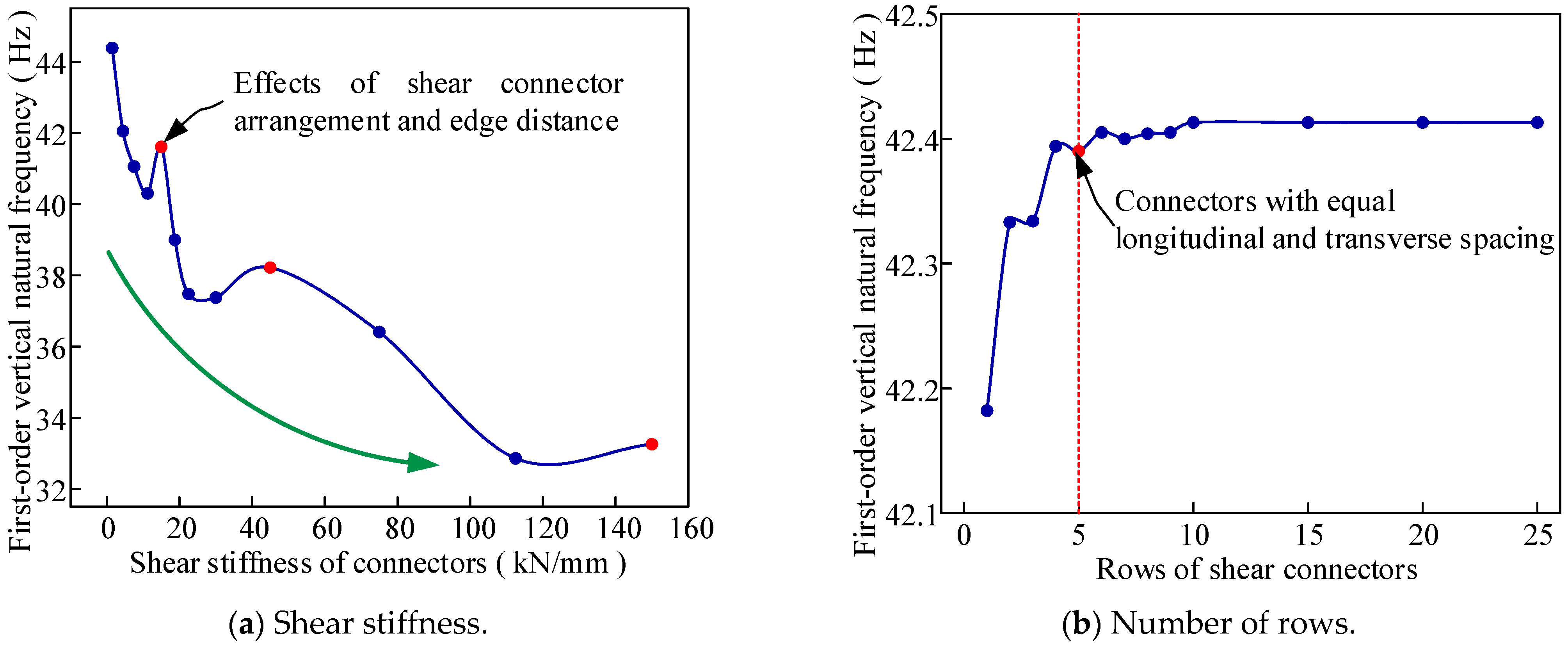
4.1. Shear Stiffness Effect

With the increase in the interlayer shear stiffness, the integrity of the composite beam is enhanced, and its vibration mode varies accordingly. This part first analyzes the influence of the synchronous change in the shear stiffness of the studs on the two interfaces.
Figure 6 reflects the first three natural vibration modes of the CSC three-layer composite beams under different interlayer connection states, in which the interlayer connection is divided into four types, namely, near-unconnected state (K1 = K2 = 0.01 MPa), partial connection (K1 = K2 = 10 MPa), complete connection (K1 = K2 = 106 MPa), and consolidation. Figure 6a–c show the natural vibration mode of the CSC beam when the interlayer is close to the unconnected state. Due to the lack of interlayer connection, the first three orders are obvious overall dislocations between the layered structures, and the first three orders are small and similar. With the increase in the shear stiffness between the layers (Figure 6d–f), the overall performance of the composite beam is enhanced, the dislocation effect between the layers is reduced, and the overall vibration mode contains the overall dislocation vibration, that is, the shear stiffness of shear connectors is insufficient to engage global vibration in multi-layer beams, the composite action remains limited. Figure 6g–i describe the vibration mode of the composite beam after the interlayer shear stiffness continues to increase. The overall performance of the composite beam with complete connection between the layers is improved, and the vibration mode is shown as the overall situation. At the same time, the natural frequency is also increased with the enhancement in the interlayer connection. Compared with the fully connected state, the mode of interlayer consolidation is consistent with the fully connected state, but the frequency is greatly improved, indicating that the integrity of the composite beam is greatly reduced under the combined state (Figure 6j–l).
Figure 7 reflects the variation in the vibration frequency of the first-order torsional, vertical, and transverse vibrations of the CSC beam with the interface shear stiffness. The relationship between the vibration frequency and the shear stiffness of the three vibration modes is consistent, showing two-stage development. Compared to the unconnected interlayer condition, the vertical, transverse, and torsional vibration frequencies under complete connection increase by 37.82%, 22.33%, and 97.33%, respectively. Among them, the large increase in the frequency of torsional vibration is caused by the torsion being affected by the sliding of each layer structure in the weak connection state.
It can be observed from Figure 7 that when the CSC beam uses shear connectors to combine each layer, although the frequencies of each order increase with the shear stiffness, there is still a big gap between the maximum frequency and the frequency when the interface is consolidated. Among them, the first-order vertical, transverse, and torsional vibration frequencies differ by 24.69%, 6.30%, and 25.52%, respectively.
In practical applications, the shear stiffness of different interfaces can be kept different. At the same time, the first-order vertical vibration is a landmark parameter regarding the characterization of the dynamic characteristics of the beam. Therefore, Figure 8 describes the variation in the first-order vertical vibration of the CSC beam with the shear stiffness of the lower interface while the shear stiffness of the upper interface is fixed (K1 = 300 MPa). Comparative analysis of Figure 7a and Figure 8 reveals that the first-order vertical natural frequency exhibits consistent two-stage growth characteristics with increasing shear stiffness, regardless of whether only the lower layer’s stiffness varies or both layers change simultaneously. Notably, the fully connected configuration achieves a 21.03% maximum frequency enhancement compared to the unconnected condition. Once the shear stiffness of the lower interface in the CSC beam is greater than 10,000 MPa, the first-order vertical frequency tends to be stable at 45.27 Hz, which is only 1.22% worse than that of the two-layer composite beam. This means that after adding the concrete structure under the concrete–steel two-layer composite beam, when the interface shear stiffness tends to be completely connected, the dynamic characteristics of the concrete–steel–concrete composite beam are similar to those of the original composite beam.
Figure 9 shows the first three natural vibration modes of the CCS beam with different upper-layer connection states, that is, the shear stiffness of the concrete–steel interface is fixed (K2 = 300 MPa), and the shear stiffness of the concrete–concrete interface ranges from 10−2 MPa to 106 MPa. When the connection between the top layers is close to the non-connection state, the natural vibration modes of the CCS and CSC beams are the same, and the difference is that the natural vibration frequency of the CCS beam is relatively large (Figure 6a–c and Figure 9a–c). When the connection between the top layers is weak, the vertical vibration becomes the first-order vibration, while the dislocation of the concrete slab occurs when the second-order vibration occurs (Figure 9d–f). Figure 9g–i describe the first three natural vibration modes of the CCS beam when the upper interface is completely connected. With the increase in the shear stiffness, the integrity of the composite beam is strengthened, and the vibration mode is shown as the overall vibration. In addition, when the upper interface is consolidated, the structure of the CCS beam is like that of a concrete–steel composite beam with doubled concrete slab thickness (Figure 9j–l).
Figure 10 describes the variation in the first-order vertical vibration frequency of the CCS beam with the shear stiffness of the upper interface. With the increase in the shear stiffness of the upper layer, the first-order vertical vibration frequency of the composite beam increases in two stages, and when the upper interface is connected, the maximum frequency of the structure is increased by 12.07% compared with that without connection. When the interface between the concrete slabs is consolidated, that is, the double-layer composite beam with twice the thickness of the concrete slab, the overall first-order vertical vibration frequency is 38.87 Hz. This frequency is less than 40.77 Hz, which is the maximum frequency of the CCS beam and approximately equal to the frequency of the CCS beam with K2 = 600 MPa. This means that for the commonly used concrete–steel double-layer composite beam, after the concrete slab is installed on the upper part to form the CCS beam, the overall dynamic performance of the CCS beam can be made consistent with that of the double-layer composite beam by reasonably designing the shear stiffness between concrete slabs.

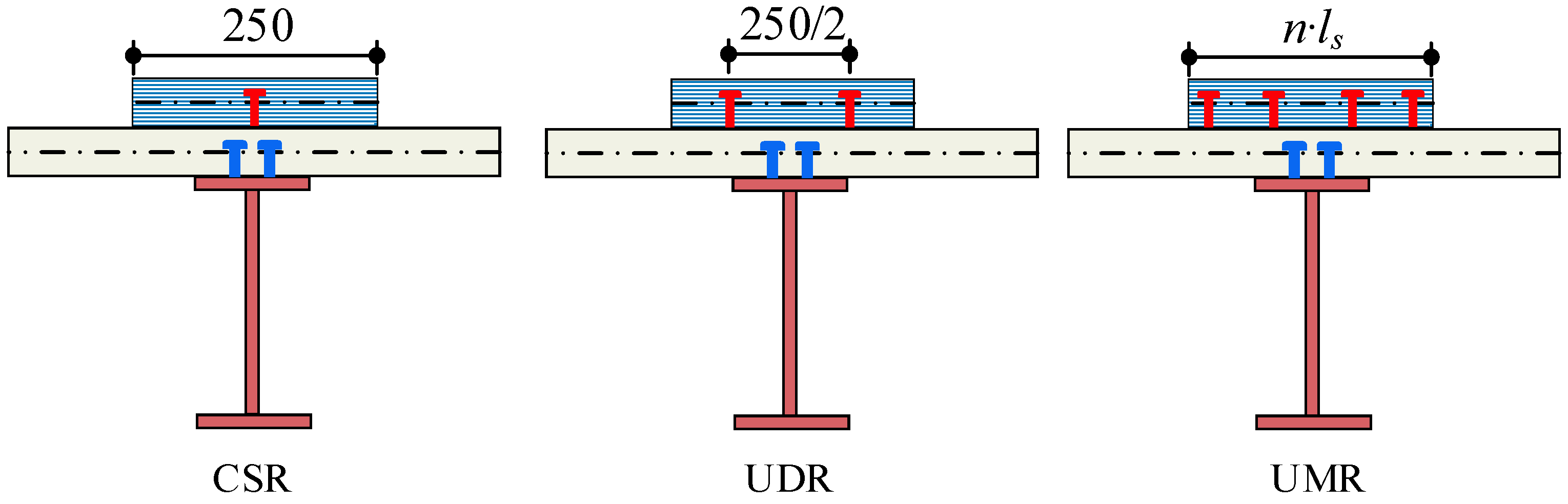
4.2. Connector Arrangement

In addition to conventional shear connectors, large-size connectors can also be used on demand. For example, to reduce the space occupied by connectors and facilitate construction, large-size studs have been applied [30]. According to the research, composite beams with a single row of studs are prone to splitting failure. This study utilizes double-row shear connectors with a fixed interfacial shear stiffness of 300 MPa. By reducing the number of studs and increasing the shear stiffness of the connectors, the relationship between the dynamic characteristics of the composite beam and the shear stiffness of the connectors is simulated.
Figure 11a reflects the variation in the first-order vertical frequency of the CSC beam with the shear stiffness of the studs. As the shear stiffness of the studs increases and the total number of studs decreases, the vertical frequency of the three-layer beam shows a downward trend as a whole. When the shear stiffness of the connectors increases from 1.5 kN/mm to 150 kN/mm, the vertical frequency decreases by 25.08%. However, due to the change in the distance between the connector and the end of the beam, the frequency is affected, and the abnormal phenomenon of local frequency increase occurs.
The arrangement of the connectors between the concrete slabs in the CCS beam can not only affect the local stress of the beam but also may affect the dynamic characteristics of the composite beam. The width of the upper concrete slab is half of the width of the lower concrete slab. The shear stiffness is fixed (K1 = 600 MPa, K2 = 300 MPa). The shear connectors between concrete slabs are arranged in a single row, a double row, or multiple rows, while the shear connectors between the concrete slab and steel beam are arranged in two rows with a lateral interval of 80 mm and a longitudinal interval of 50 mm. The arrangement methods for connectors between concrete slabs are illustrated in Figure 12.
Figure 11b describes the variation in the first-order vertical vibration frequency of the CCS beam with the number of rows of connectors. With the increase in the number of rows, the uniformity of the connector arrangement is improved. The first-order vertical vibration frequency of the composite beam is increased until the connectors reach 10 rows; at this point, the frequency reaches the maximum, but the increase is very small. When the longitudinal and transverse spacings are the same, the frequency of the composite beam is close to the maximum. To control the overall stability of the composite beam, the connectors should avoid a single-row arrangement as much as possible, and the multi-row connectors should be arranged with longitudinal and transverse spacing.

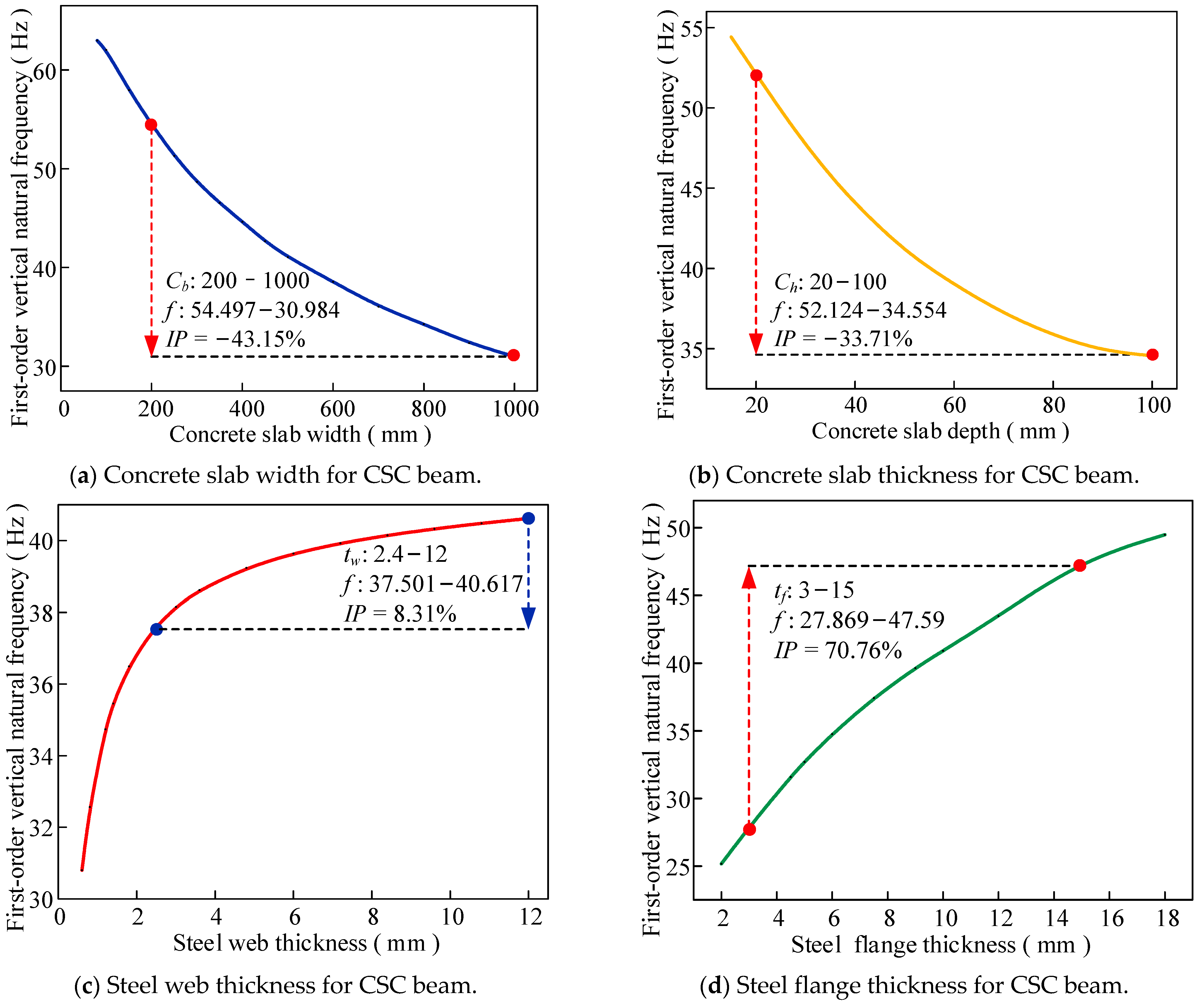
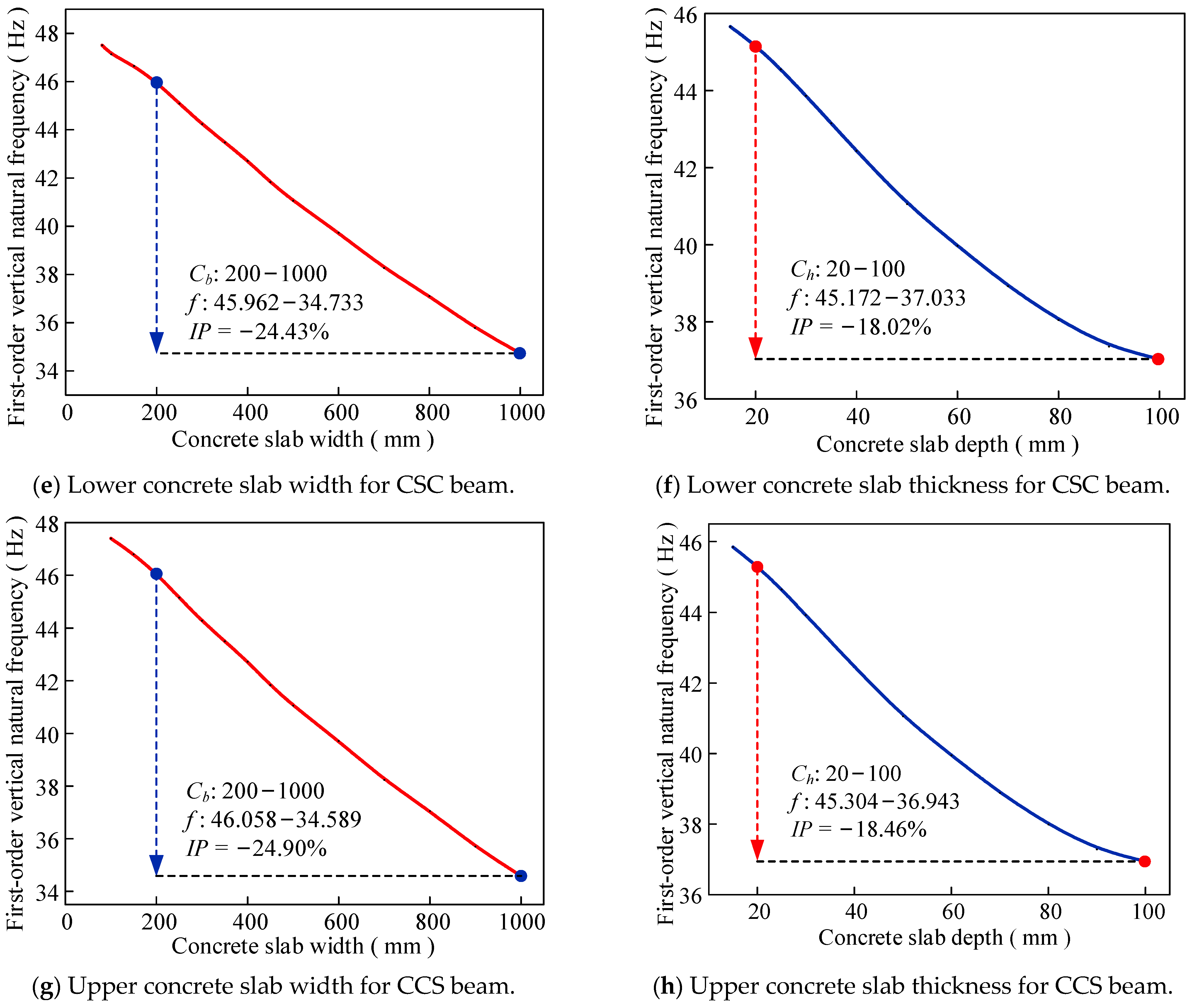
4.3. The Effect of Concrete Slab and Steel Beam Size

To study the effect of structural parameters on the dynamic characteristics of three-layer composite beams, this part analyzes the width and thickness of concrete slabs, the height and thickness of steel webs, and the span–depth ratio L/H.
Figure 13a–d reflect the relationship between the first-order vertical vibration frequency of the CSC beam and the size of the concrete slab and steel beam, where the shear stiffness of the upper and lower interfaces of the CSC beam is set to be consistent (K1 = K2 = 300 MPa). The first-order frequencies of the CSC beams decrease and increase with the increase in the concrete slab size (width and thickness) and steel beam size (steel flange and web thickness), respectively. This is because the frequency of the CSC beam is lower than that of the steel beam and higher than that of the concrete slab. With the increase in the size of the concrete slab and steel beam, the dynamic characteristics of the CSC beam are close to those of the concrete slab and steel beam. The first-order vertical natural frequency exhibits reductions of 43.15% and 33.71% respectively for fivefold increases in concrete slab width and depth, while demonstrating increases of 8.31% and 70.76% corresponding to quintupled steel web and flange thickness variations, revealing distinct mass-dominated and stiffness-governed behavioral regimes in composite beam dynamics. It can be seen that for the three-layer concrete–steel–concrete composite beam, the first-order vertical vibration frequency is most sensitive to the steel flange thickness, followed by the width and thickness of the concrete plate, and the steel web thickness has the least influence on the first-order vertical vibration frequency.
To enhance the global stability of steel–concrete composite beams or meet structural strengthening requirements, additional concrete slabs may be incorporated at either the bottom or top of the original beam. The influence of the width and height of these newly added concrete slabs on the fundamental vertical vibration frequency of the composite beam is illustrated in Figure 13e–h. As demonstrated in the results, the fundamental vertical vibration frequency of the composite beam decreases linearly with the increasing dimensions of both the upper and lower concrete slabs. Notably, the width of the concrete slab exhibits a more pronounced effect on vibration frequency reduction compared to its height.
As shown in Figure 14, the fundamental vertical vibration frequency of CSC composite beams exhibits a two-stage decreasing trend with an increasing span–depth ratio L/H. To ensure the structural stability and optimal performance of the composite system, it is recommended that the L/H of triple-layer steel–concrete composite beams be maintained at no less than 10.

5. Conclusions

In this paper, solid dynamic analysis models of concrete–steel–concrete (CSC) and concrete–concrete–steel (CCS) three-layer composite beams are established, and the accuracy of the analysis model establishment method is verified after comparison with the concrete–steel composite beam test. The dynamic characteristics of the CSC and CCS beams are analyzed, and the following conclusions are drawn:
(1)
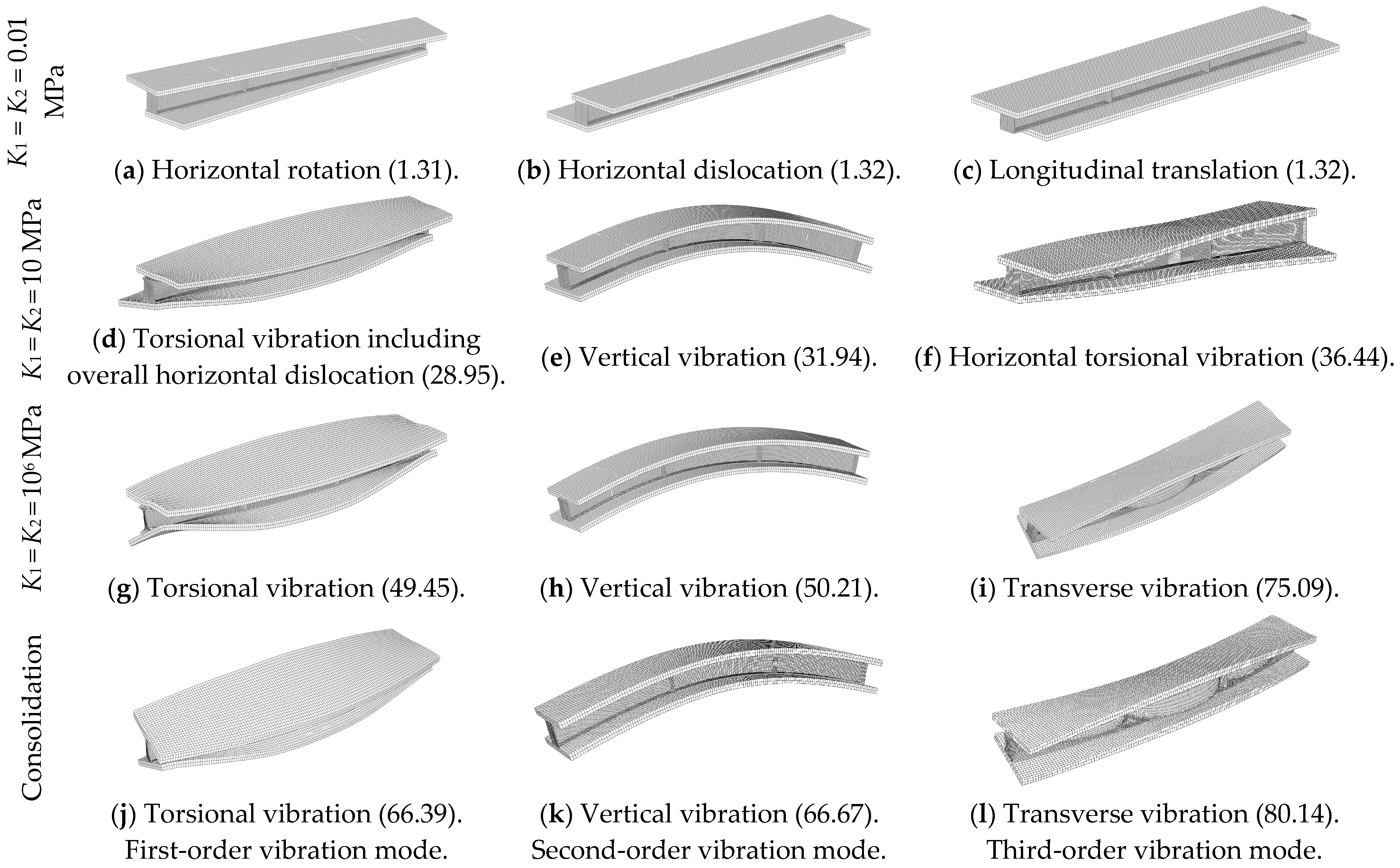
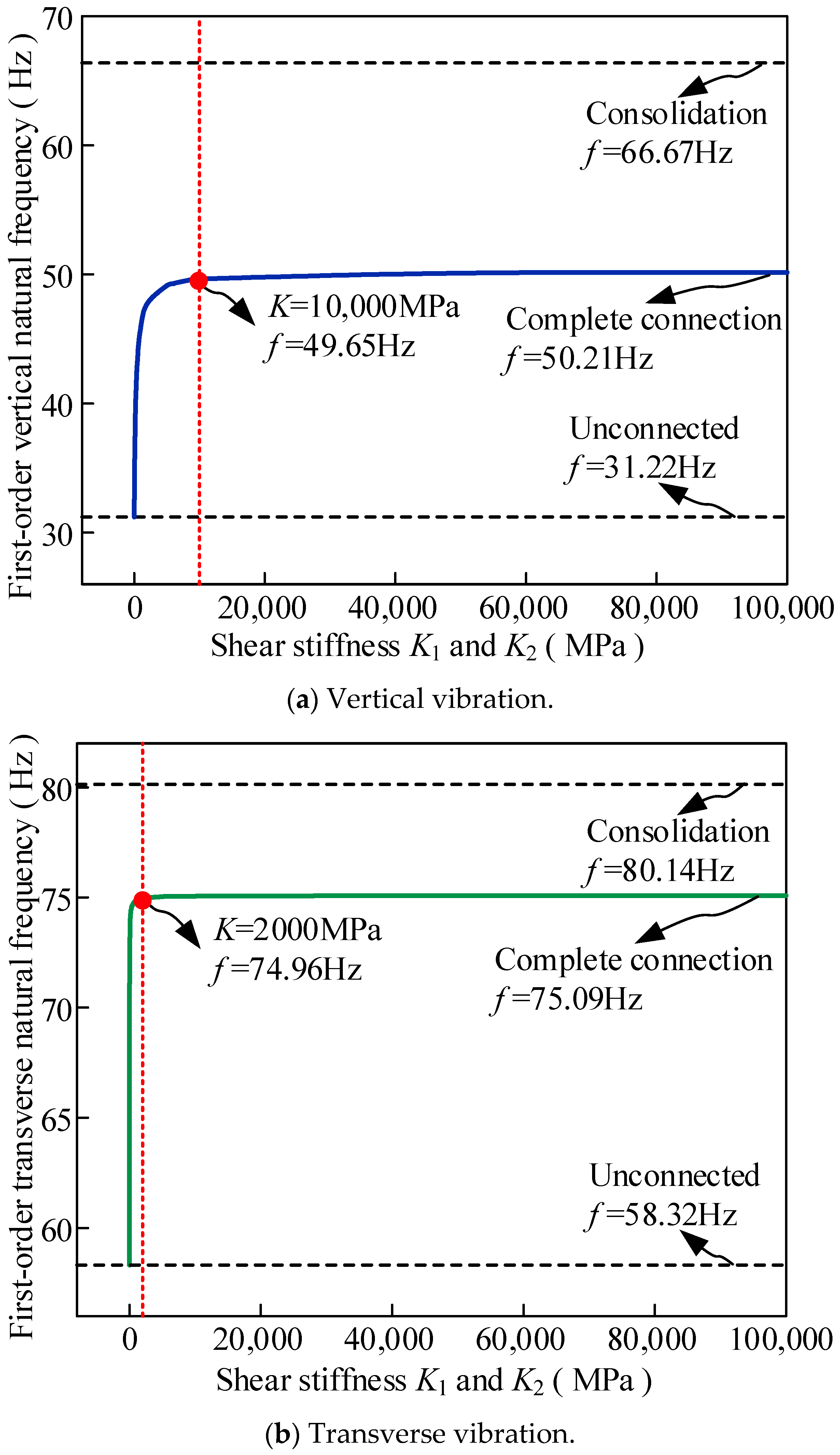
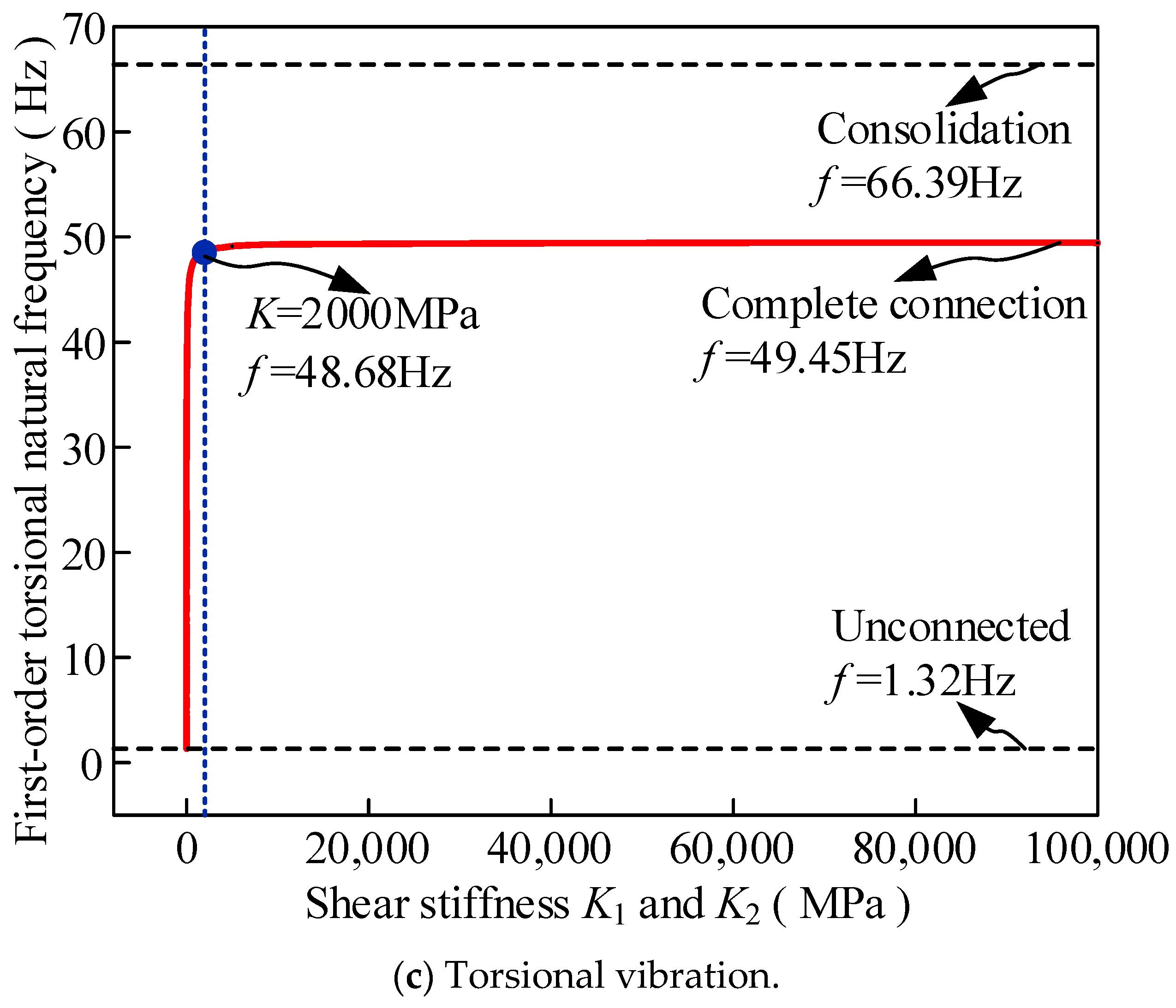
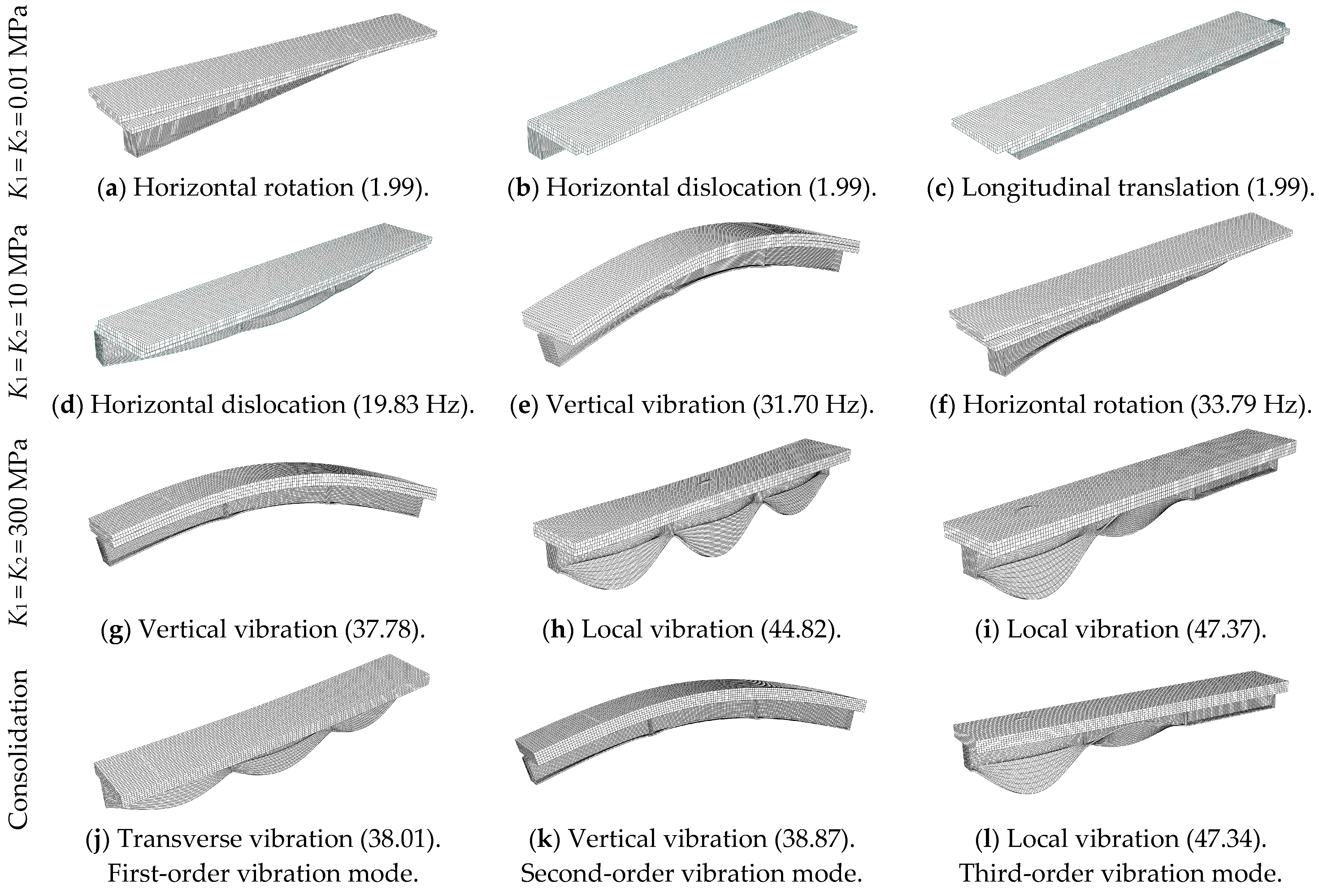
The vibration characteristics analysis demonstrates that the natural frequencies of triple-layer steel–concrete composite beams exhibit a distinct two-stage increasing pattern with the enhancement in shear stiffness in interlayer connectors. Specifically, the frequency shows rapid growth during the initial stiffness increase phase, then transitions to a gradual growth phase upon reaching a critical stiffness threshold.
(2)
For CSC-type simply supported composite beams, the fundamental vertical vibration frequency increases by 37.82% when achieving full shear connection at both interfaces compared to the unconnected state, while the two-equal-span continuous beams show a 38.06% improvement. However, significant differences remain between the fully shear-connected state and theoretical rigid-bonding condition, with frequency discrepancies of 24.69% for simply supported beams and 24.07% for continuous beams. Notably, CCS-type simply supported beams display a 12.07% frequency increase with full concrete-to-concrete connection, exceeding even the theoretical rigid-bonding frequency value.
(3)
The structural parameters influencing dynamic performance are prioritized as follows: steel flange plate thickness (most significant), followed by concrete slab width and thickness, with steel web thickness showing a relatively minor effect.
(4)
The non-uniformity of the longitudinal connector arrangement considerably affects the dynamic characteristics, while the transverse arrangement pattern demonstrates limited influence.
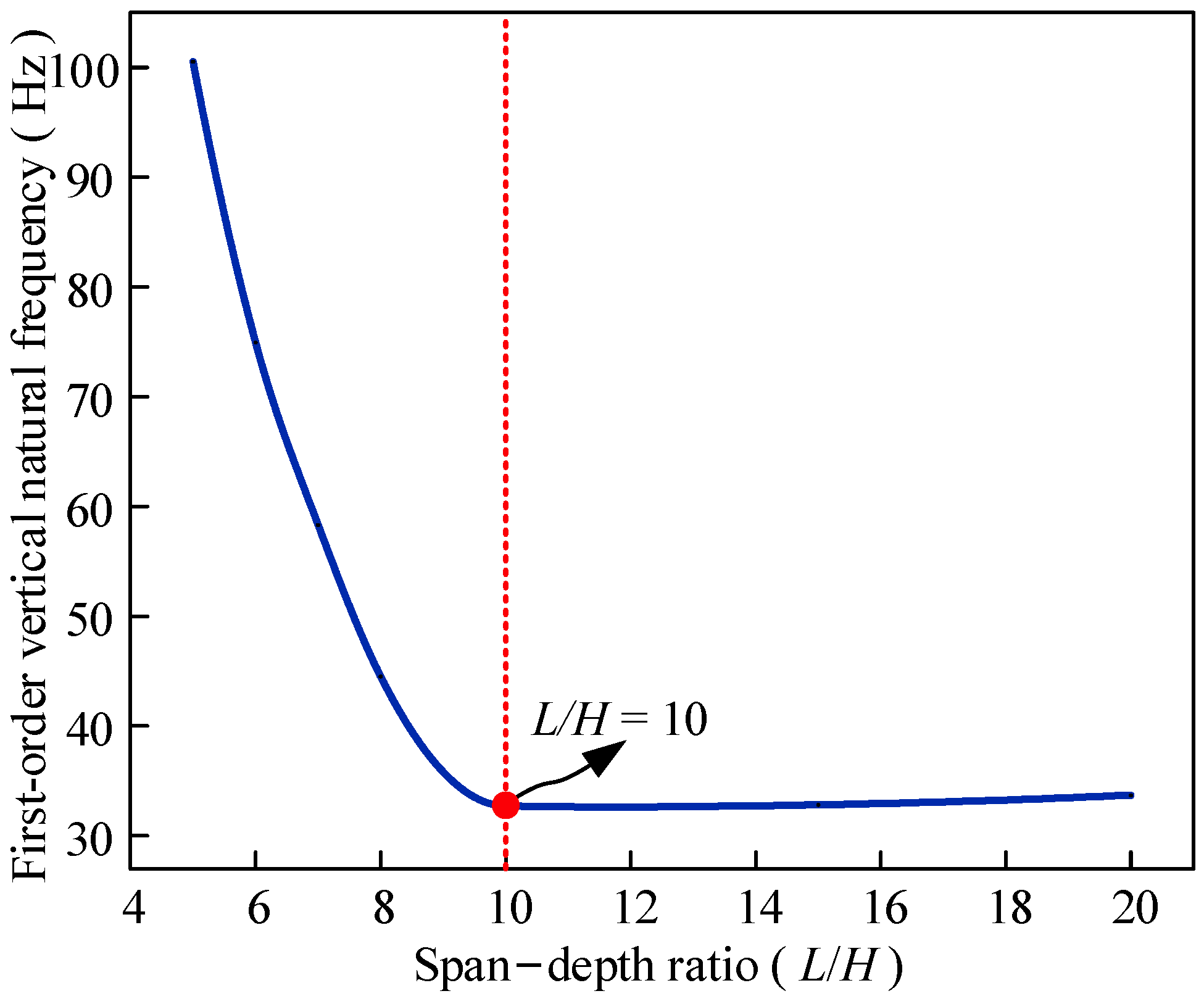
(5)
The fundamental vertical vibration frequency presents a two-stage decreasing trend with an increasing span-to-depth ratio. Considering both stability and dynamic performance requirements, a minimum span-to-depth ratio of 10 is recommended for triple-layer steel–concrete composite beams.

Author Contributions

Conceptualization, Y.H.; Methodology, L.Y.; Software, L.C.; Validation, X.H.; Formal analysis, M.C.; Investigation, B.Y.; Resources, Y.Y.; Writing—original draft, B.L. All authors have read and agreed to the published version of the manuscript.

Funding

This research was supported by the “2025 Science and Technology Innovation Program” (Project No. KY-2025-TM-006) of Beijing Urban Construction Group Co., Ltd. (BUCG) Civil Engineering General Contracting Department, the Fundamental Research Funds for the Central Universities (Grant No. 2019YJS124), and the Research on Key Technologies of Guanfo Expressway Maintenance Project (Project No. 0222KF06SC1123).

Data Availability Statement

The authors confirm that the data supporting the findings of this study are available within the article.

Conflicts of Interest

Authors Longbiao Yan and Long Cao were employed by the company Beijing Urban Construction Group Co., Ltd. Author Yachen You was employed by the company CCCC Road and Bridge Construction Co., Ltd. Author Benyuan Li was employed by the company Beijing Urban Construction Design & Development Group Co., Ltd. The remaining authors declare that the research was conducted in the absence of any commercial or financial relationships that could be construed as a potential conflict of interest.

References

  1. Kefal, A.; Tessler, A.; Oterkus, E. An enhanced inverse finite element method for displacement and stress monitoring of multilayered composite and sandwich structures. Compos. Struct. 2017, 179, 514–540. [Google Scholar] [CrossRef]
  2. Lee, D.S.; Morillo, C.; Bugeda, G.; Oller, S.; Onate, E. Multilayered composite structure design optimisation using distributed/parallel multi-objective evolutionary algorithms. Compos. Struct. 2012, 94, 1087–1096. [Google Scholar] [CrossRef]
  3. Han, T.; Wang, X.; Xiong, Y.; Li, J.; Guo, S.; Chen, G. Light-weight poly(vinyl chloride)-based soundproofing composites with foam/film alternating multilayered structure. Compos. Part A Appl. Sci. Manuf. 2015, 78, 27–34. [Google Scholar] [CrossRef]
  4. Sahloddin, Y.; Dalvand, A.; Ahmadi, M.; Hatami, H.; Khaneghahi, M.H. Performance evaluation of built-up composite beams fabricated using thin-walled hollow sections and self-compacting concrete, Construction and Building Materials. Constr. Build. Mater. 2021, 305, 124645. [Google Scholar] [CrossRef]
  5. Sun, Y.; Chen, J.; Ma, F.; Ameyama, K.; Xiao, W.; Ma, C. Tensile and flexural properties of multilayered metal/intermetallics composites. Mater. Charact. 2015, 102, 165–172. [Google Scholar] [CrossRef]
  6. Deng, X.; Chawla, N.; Chawla, K.K.; Koopman, M.; Chu, J.P. Mechanical behavior of multilayered nanoscale metal-ceramic composites. Adv. Eng. Mater. 2005, 7, 1099–1108. [Google Scholar] [CrossRef]
  7. Deng, Y.; Zhang, W.; Cao, Z. Experimental investigation on the ballistic resistance of monolithic and multi-layered plates against hemispherical-nosed projectiles impact. Mater. Des. 2012, 41, 266–281. [Google Scholar] [CrossRef]
  8. Wang, D. Compressive constitutive relation for multi-layer corrugated boards. Appl. Mech. Mater. 2011, 80, 365–369. [Google Scholar] [CrossRef]
  9. Stroh, S.L.; Sen, R.; Ansley, M. Load testing a double-composite steel box girder bridge. Transp. Res. Rec. 2010, 2200, 36–42. [Google Scholar] [CrossRef]
  10. Stroh, S.L.; Sen, R. Steel bridges with double-composite action: Innovative design. Transp. Res. Rec. 2000, 1, 299–309. [Google Scholar] [CrossRef]
  11. Kim, H.H.; Shim, C.S. Experimental investigation of double composite twin-girder railway bridges. J. Constr. Steel Res. 2009, 65, 1355–1365. [Google Scholar] [CrossRef]
  12. Mahmoud, A.M. Finite element modeling of steel concrete beam considering double composite action. Ain Shams Eng. J. 2016, 7, 73–88. [Google Scholar] [CrossRef]
  13. Sun, Q.; Liu, X.; Zhang, N. An accurate solution method for the dynamic characteristics of three-layered partial-interaction composite beams. Structures 2023, 56, 104928. [Google Scholar] [CrossRef]
  14. He, J.; Wang, S.; Liu, Y.; Wang, D.; Xin, H. Shear behavior of steel I-girder with stiffened corrugated web, Part II: Numerical study. Thin-Walled Struct. 2020, 147, 106025. [Google Scholar] [CrossRef]
  15. Choi, J.H.; Jung, K.H.; Kim, T.K.; Kim, J.H.J. Analytical and experimental studies on torsional behavior of hybrid truss bridge girders with various connection joints. J. Adv. Concr. Technol. 2014, 12, 478–495. [Google Scholar] [CrossRef]
  16. Guo, Y.T.; Nie, X.; Fan, J.S.; Tao, M.X. Shear resistance of steel-concrete-steel deep beams with bidirectional webs. Steel Compos. Struct. 2022, 42, 299–313. [Google Scholar] [CrossRef]
  17. Du, F.; Li, D.; Li, Y. Fracture mechanism and damage evaluation of FRP/Steel–concrete hybrid girder using acoustic emission technique. J. Mater. Civ. Eng. 2019, 31, 04019111. [Google Scholar] [CrossRef]
  18. Yang, S.C.; Hwang, S.H. Train-track-bridge interaction by coupling direct stiffness method and mode superposition method. J. Bridg. Eng. 2016, 21, 04016058. [Google Scholar] [CrossRef]
  19. Yang, S.C.; Jang, S.Y. Track–Bridge Interaction Analysis Using Interface Elements Adaptive to Various Loading Cases. J. Bridg. Eng. 2016, 21, 04016056. [Google Scholar] [CrossRef]
  20. Iurlaro, L.; Ascione, A.; Gherlone, M.; Mattone, M.; Di Sciuva, M. Free vibration analysis of sandwich beams using the Refined Zigzag Theory: An experimental assessment. Meccanica 2015, 50, 2525–2535. [Google Scholar] [CrossRef]
  21. He, G.; Wang, D.; Yang, X. Analytical solutions for free vibration and buckling of composite beams using a higher order beam theory. Acta Mech. Solida Sin. 2016, 29, 300–315. [Google Scholar] [CrossRef]
  22. Hu, L.Y.; Chen, W.Q.; Zhang, Z.C.; Xu, R.Q. Free vibration analysis of concrete beams with corrugated steel webs based on Zig-zag theory. J. Zhejiang Univ. 2019, 53, 503–511. [Google Scholar] [CrossRef]
  23. Gattesco, N. Analytical modeling of nonlinear behavior of composite beams with deformable connection. J. Constr. Steel Res. 1999, 52, 195–218. [Google Scholar] [CrossRef]
  24. Ollgaard, J.G.; Slutter, R.G.; Fisher, J.W. Shear strength of stud connectors in lightweight and normalweight concrete. Eng. J. Am. Inst. Steel Constr. 1971, 8, 55–64. [Google Scholar]
  25. China MOHUR. Code for Design of Composite Structures; Industrial Building Press of China: Beijing, China, 2016. [Google Scholar]
  26. Ranzi, G. Locking Problems in the Partial Interaction Analysis of Multi-Layered Composite Beams. Eng. Struct. 2008, 30, 2900–2911. [Google Scholar] [CrossRef]
  27. Sousa, J.R.; João Batista, M. Exact Finite Elements for Multilayered Composite Beam-Columns with Partial Interaction. Comput. Struct. 2013, 123, 48–57. [Google Scholar] [CrossRef]
  28. Keo, P.; Nguyen, Q.H.; Somja, H.; Hjiaj, M. Derivation of the Exact Stiffness Matrix of Shear-Deformable Multi-Layered Beam Element in Partial Interaction. Finite Elem. Anal. Des. 2016, 112, 40–49. [Google Scholar] [CrossRef]
  29. Lin, J.P.; Liu, X.; Wang, Y.; Xu, R.; Wang, G. Static and Dynamic Analysis of Three-Layered Partial-Interaction Composite Structures. Eng. Struct. 2022, 252, 113581. [Google Scholar] [CrossRef]
  30. El-Zohairy, A.; Salim, H.; Shaaban, H. Experimental investigation on fatigue behavior of composite beams with different studs arrangements. Structures 2022, 35, 146–159. [Google Scholar] [CrossRef]
Figure 1. A sketch of a three-layer composite beam.
Buildings 15 01347 g001
Figure 2. Hammering test of self-vibration characteristics of steel–concrete composite beams (mm). (a) Test process. (b) The arrangement of vertical vibration pickups for measuring vertical bending vibration. (c) The arrangement of vertical vibration pickups for measuring torsional vibration.
Buildings 15 01347 g002
Figure 3. FE analysis model of double-layer composite beam.
Buildings 15 01347 g003
Figure 4. Shear–slip constitutive curve of stud.
Buildings 15 01347 g004
Figure 5. Solid dynamic analysis model of three-layer composite beam structure. (a) The CSC beam. (b) Cross section of the CSC beam. (c) The CCS beam. (d) Cross section of the CCS beam.
Buildings 15 01347 g005
Figure 6. The first three natural vibration modes and frequencies of the CSC beam (Hz).
Buildings 15 01347 g006
Figure 7. Relationship between first-order vertical, transverse, and torsional vibration frequency of the CSC beam and interface shear stiffness.
Buildings 15 01347 g007aBuildings 15 01347 g007b
Figure 8. Relationship between the first-order vertical vibration frequency of the CSC beam and the interface shear stiffness K2.
Buildings 15 01347 g008
Figure 9. The first three natural vibration modes and frequencies of the CCS beam (Hz).
Buildings 15 01347 g009
Figure 10. Relationship between first-order vertical vibration frequency of the CCS beam and shear stiffness of the interface between concrete slabs.
Buildings 15 01347 g010
Figure 11. Relationship between vertical frequency and studs.
Buildings 15 01347 g011
Figure 12. Arrangement methods for connectors between concrete slabs.
Buildings 15 01347 g012
Figure 13. The variation in the first-order vertical vibration frequency of the CSC beam with the geometric parameters of the structure.
Buildings 15 01347 g013aBuildings 15 01347 g013b
Figure 14. Relationship between span–depth ratio and fundamental frequency.
Buildings 15 01347 g014
Table 1. Parameters of steel–concrete composite beams.
Shear Connection Degree100% Shear Connection Degree75% Shear Connection Degree50% Shear Connection Degree
NumberFB-1PB-1PB-2
Beam length (mm) 3200
Steel beam (mm)HM 200 × 194 × 6 × 9 hot-rolled H-beam
Steel beam rib plate (mm)8 ribs on both sides of the web, with a size of 194 × 75 × 6 and a spacing of 1000
Concrete slab (mm)Strength C50, size 500 × 80
Stud (mm)Φ 10, height 30
Longitudinal spacing of studs (mm)250250, 500500
Transverse spacing of studs (mm)80
Number of studs261814
Transverse reinforcement (mm)Φ 6@120, HPB235
Longitudinal reinforcement (mm)Φ 10@90, HPB235
Table 2. Dynamic test results of steel–concrete composite beams.
NumberFB-1PB-1PB-2
Shear connection degree1.040.720.56
First-order vertical vibration frequency (Hz)45.7744.2841.88
First-order torsional vibration frequency (Hz)54.7352.2447.51
Table 3. Verification of the solid dynamic analysis model of the steel–concrete composite beam.
NumberFB-1PB-1PB-2
ModelingErrorModelingErrorModelingError
Buildings 15 01347 i001
First-order vertical
vibration frequency (Hz)
45.281.07%44.941.49%41.071.93%
Buildings 15 01347 i002
First-order torsional
vibration frequency (Hz)
54.670.11%56.325.79%46.202.76%
Disclaimer/Publisher’s Note: The statements, opinions and data contained in all publications are solely those of the individual author(s) and contributor(s) and not of MDPI and/or the editor(s). MDPI and/or the editor(s) disclaim responsibility for any injury to people or property resulting from any ideas, methods, instructions or products referred to in the content.

