
Experimental and Numerical Research on the Mechanical Properties of a Novel Prefabricated Diaphragm Wall–Beam Joint

Abstract
1. Introduction
2. Experimental Program
2.1. Materials
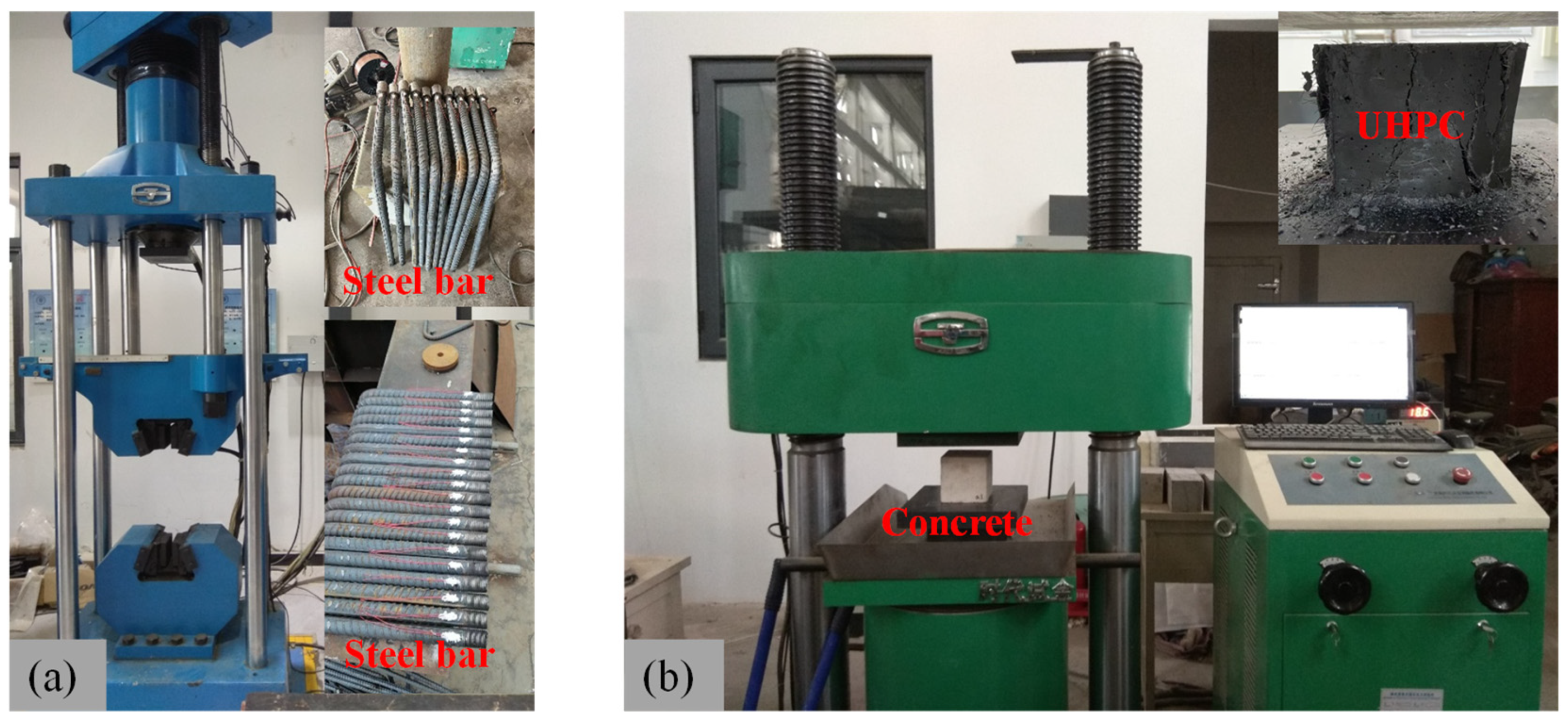
2.1.1. Steel Bars
2.1.2. Concrete
2.1.3. UHPC
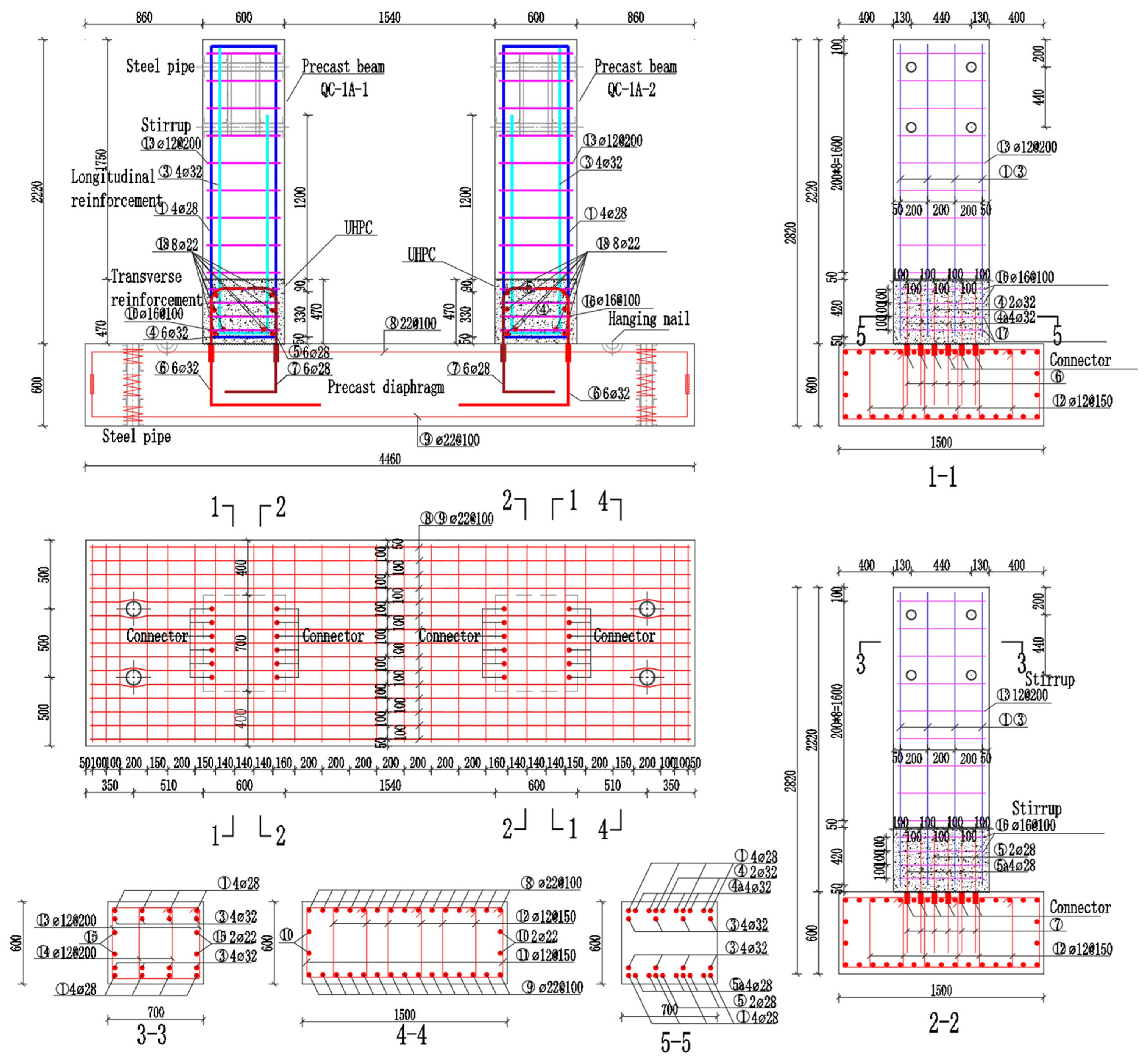
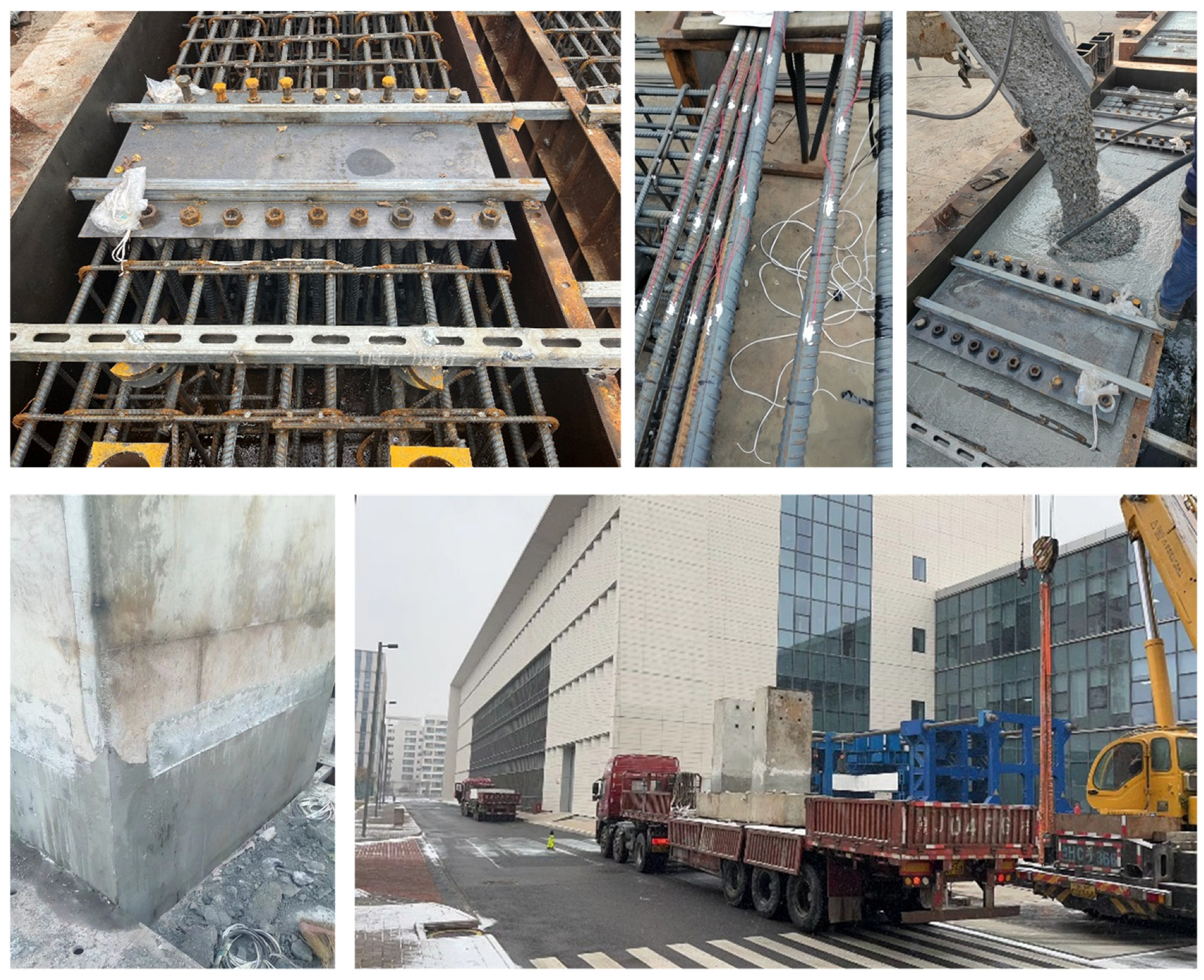
2.2. Experimental Design and Specimen Fabrication
2.3. Loading and Measurement Scheme
3. Experimental Results
3.1. Experiment Phenomenon and Failure Modes
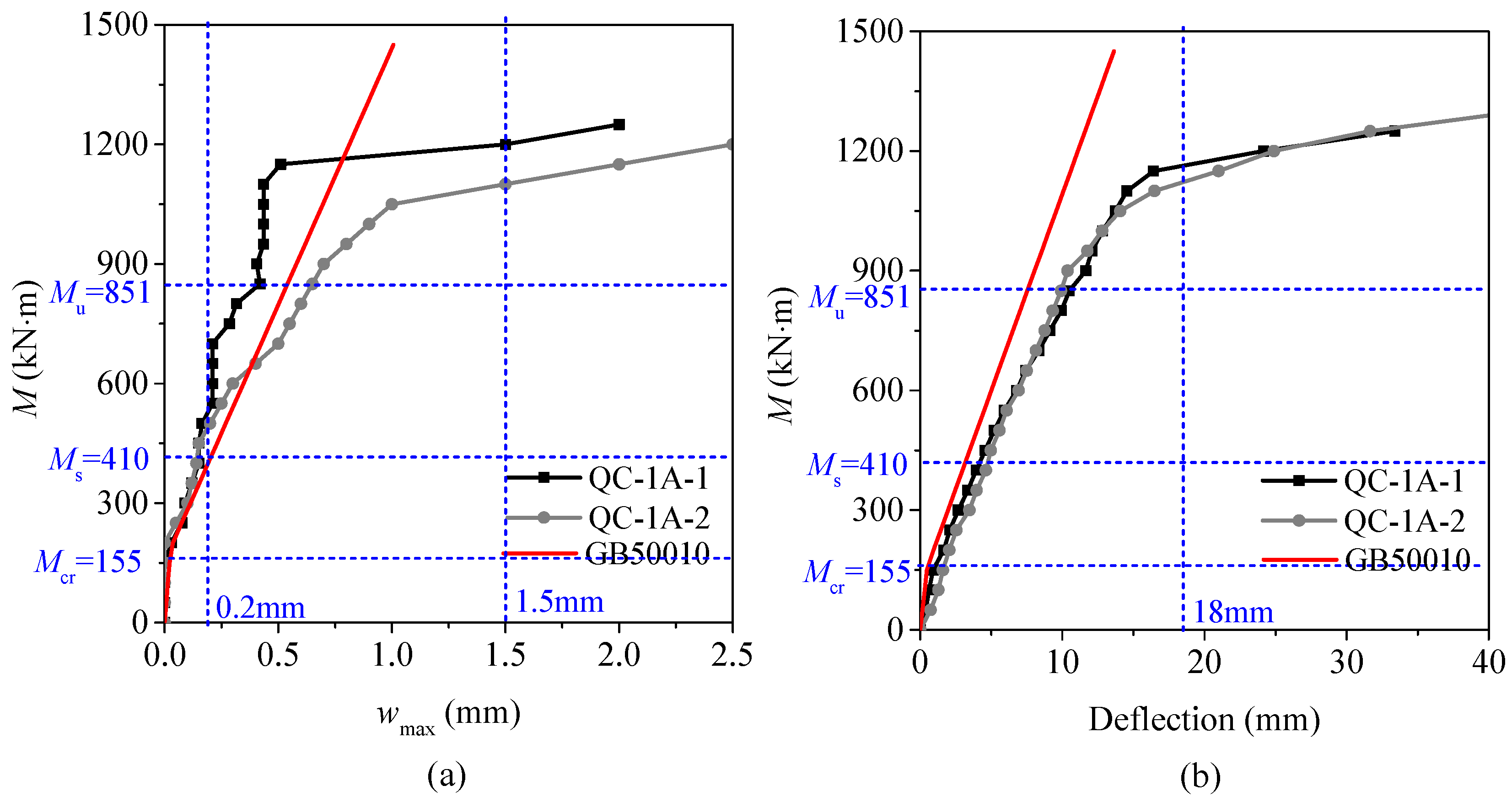
3.2. Crack Development
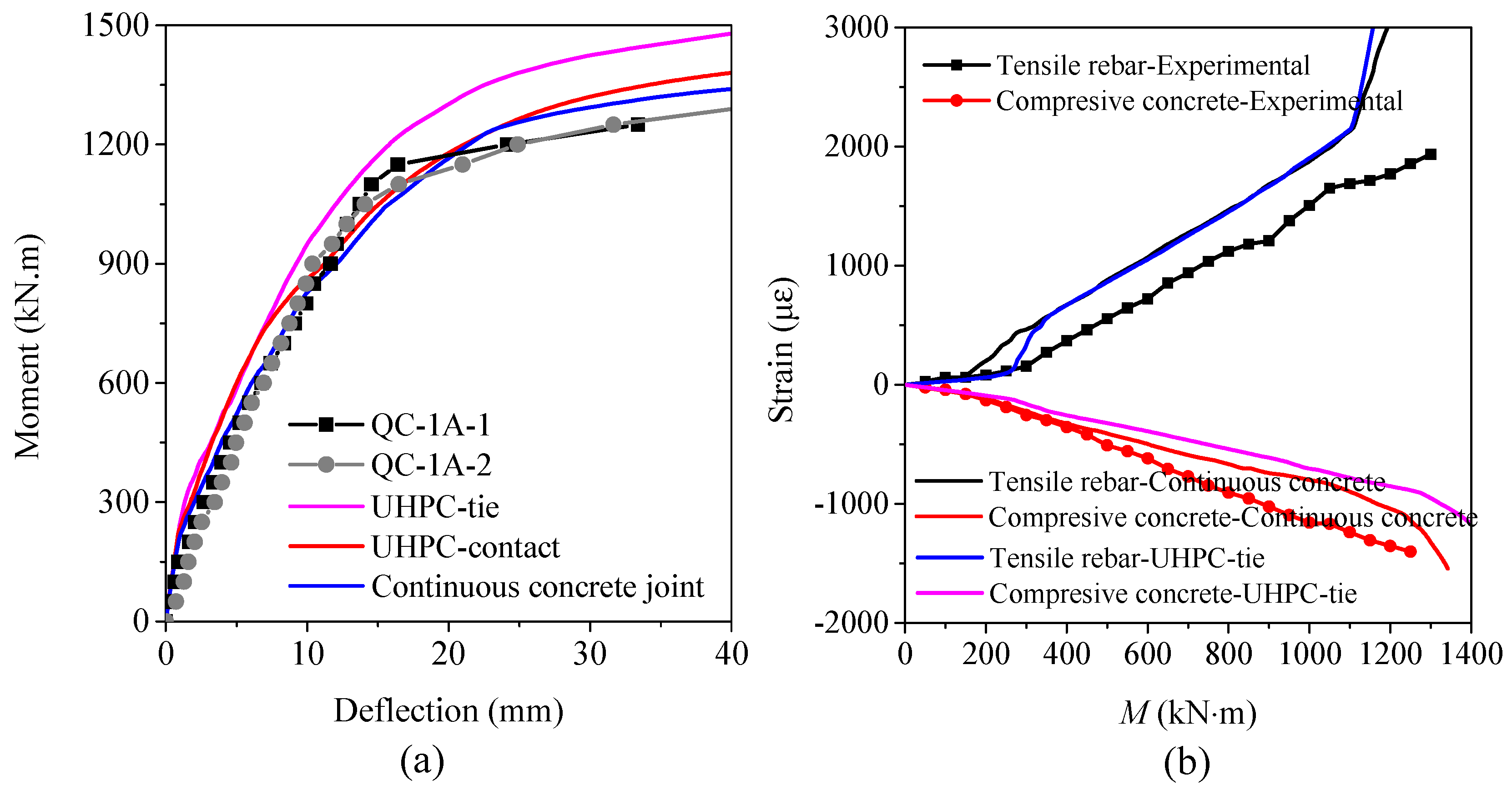
3.3. Deflection Curves
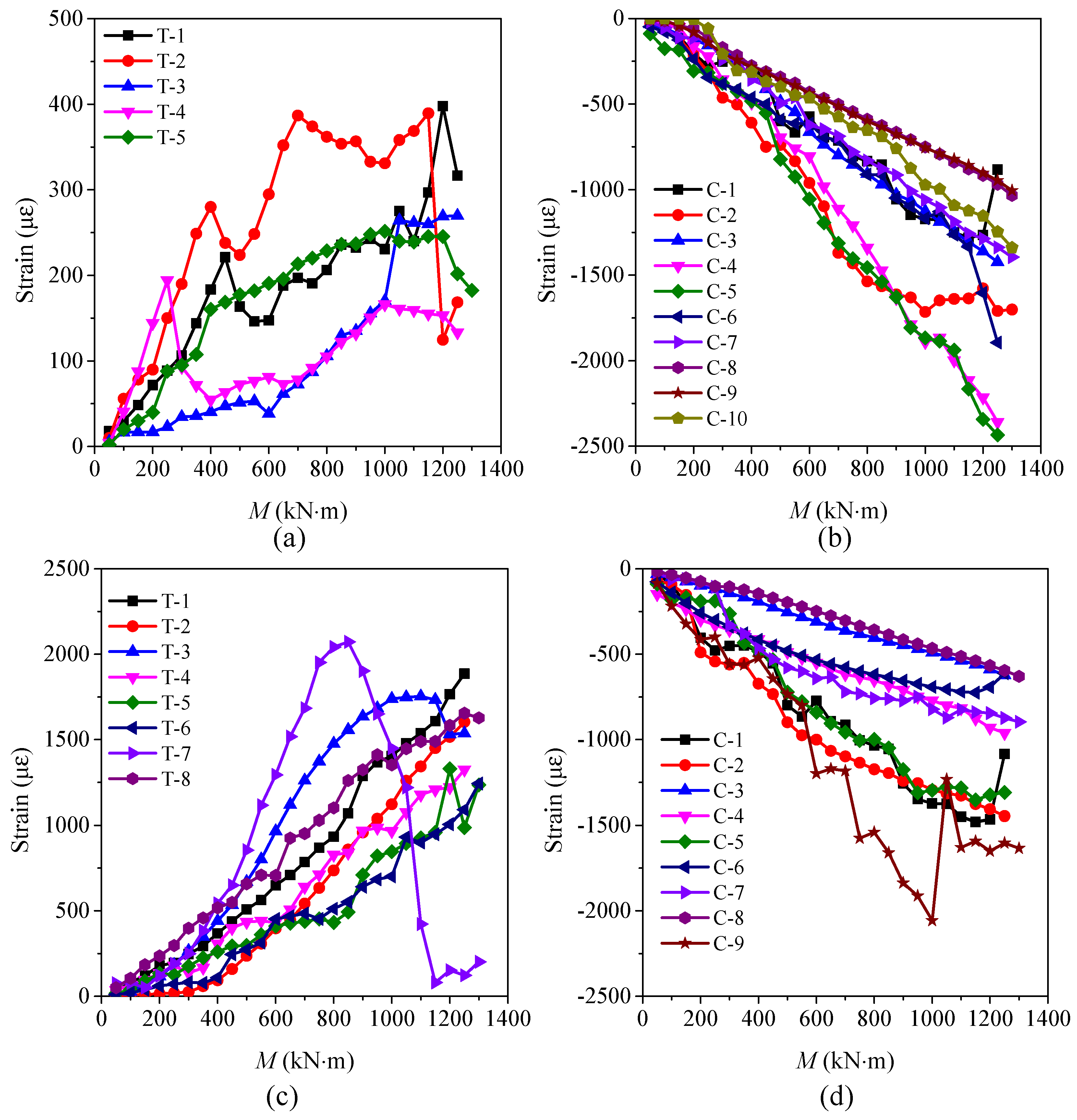
3.4. Strain Development
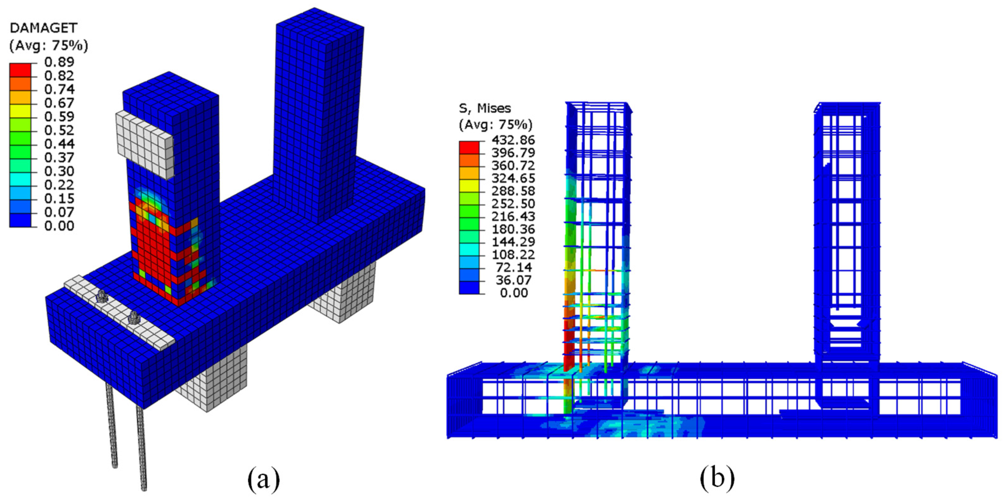
4. Finite Element Analysis
4.1. Material Model
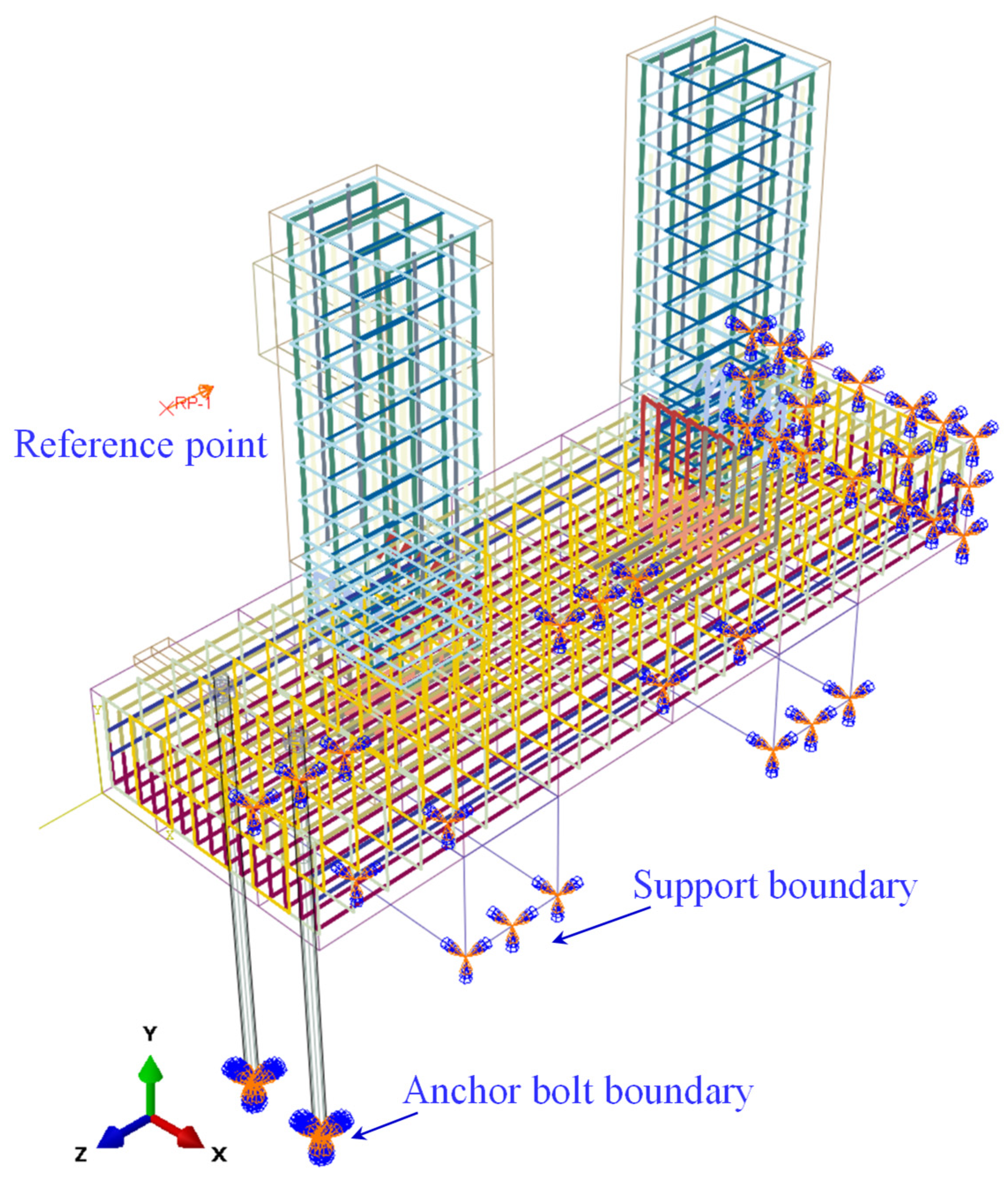
4.2. Finite Element Model
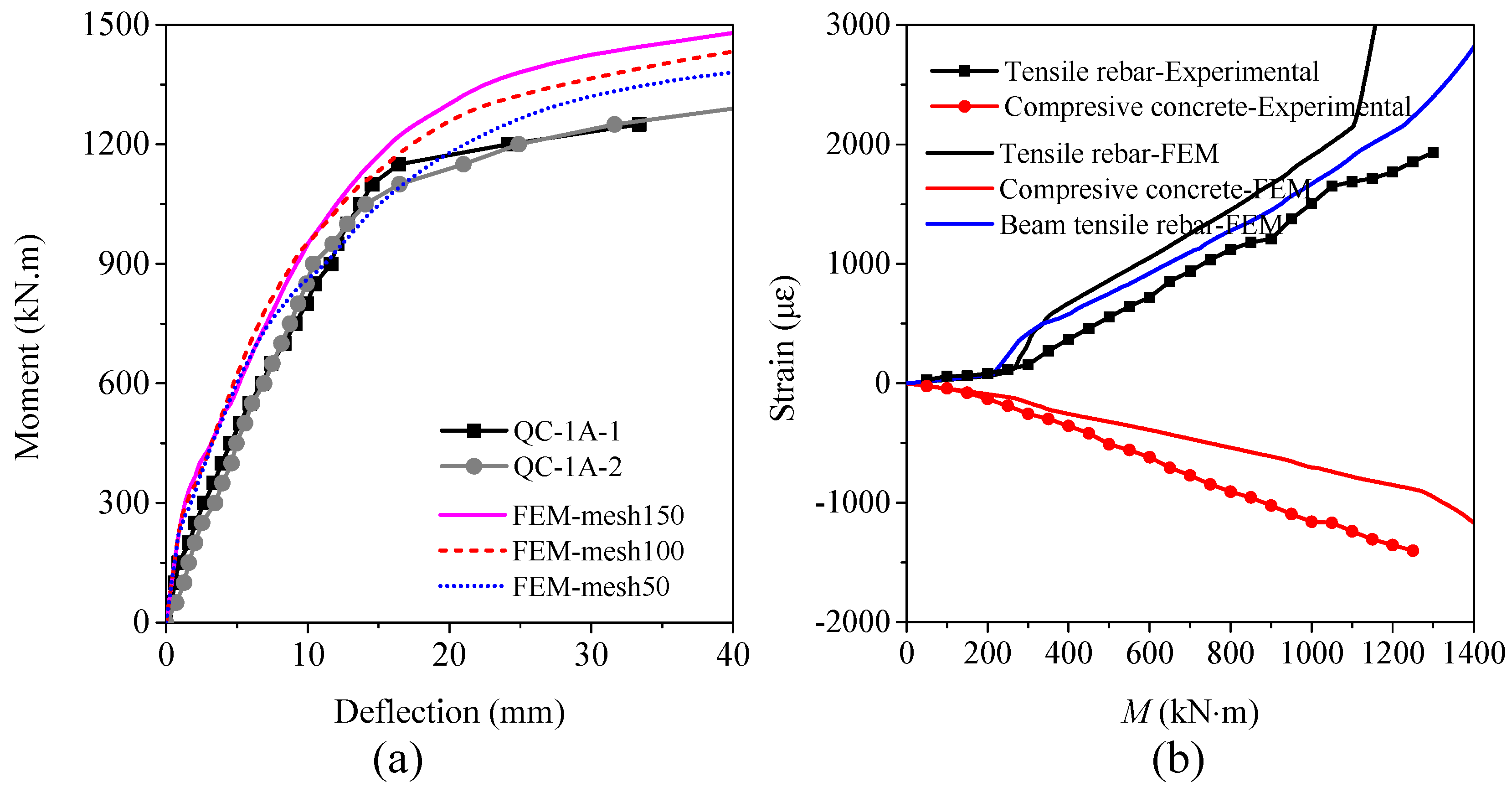
4.3. Model Validation
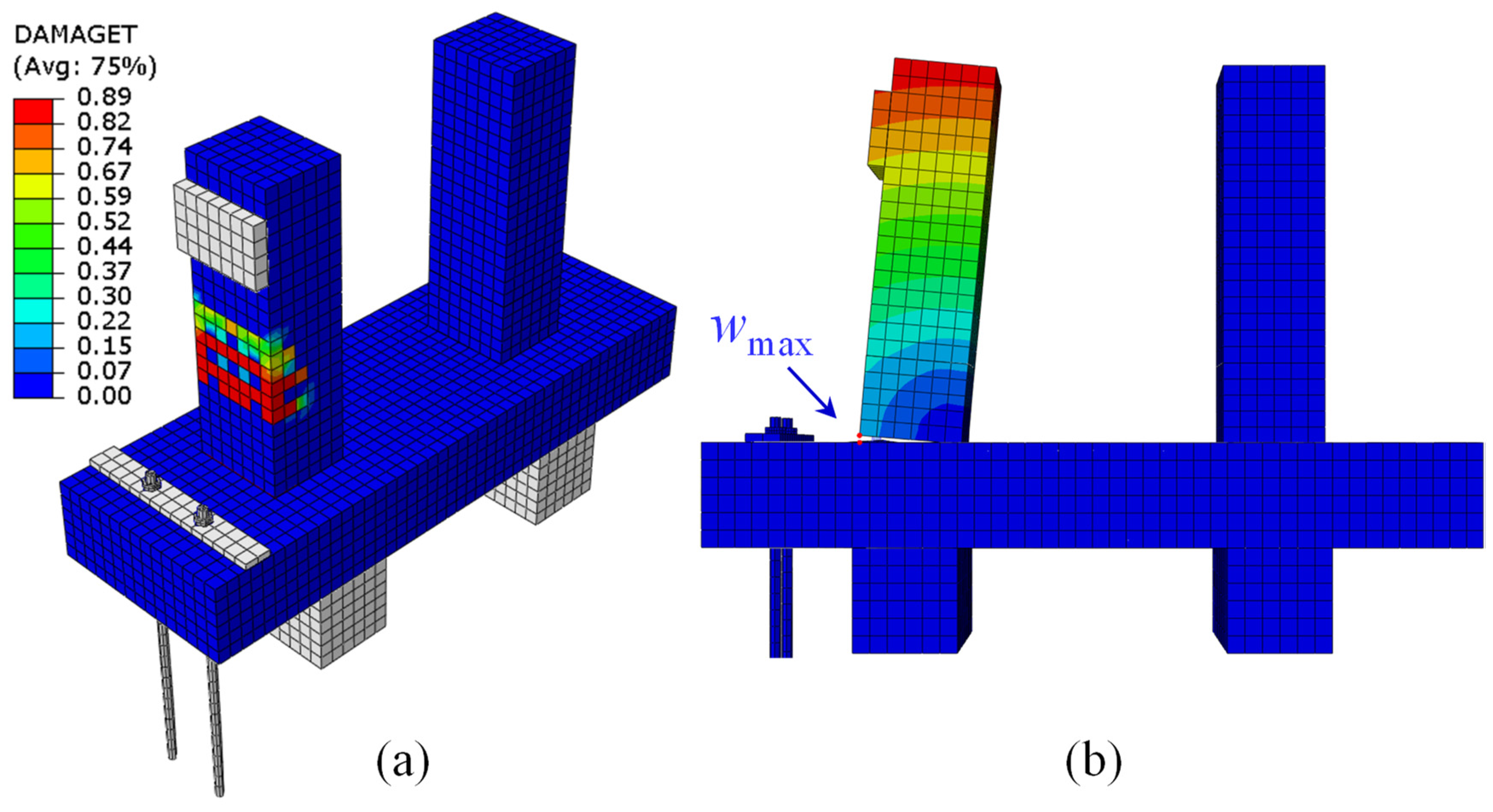
4.4. Interface Behavior Analysis
4.5. Continuous Concrete Joint
5. Future Study
6. Conclusions
Author Contributions
Funding
Data Availability Statement
Conflicts of Interest
References
- Chang, R.; Zhang, N.; Gu, Q. A Review on Mechanical and Structural Performances of Precast Concrete Buildings. Buildings 2023, 13, 1575. [Google Scholar] [CrossRef]
- Chen, K.; Chen, X.; Wang, L.; Yang, W.; Qiu, T.; Su, D.; Wu, H. Low-Carbon Effects of Constructing a Prefabricated Subway Station with Temporary Internal Supports: An Innovative Case of Shenzhen, China. J. Clean. Prod. 2023, 426, 139023. [Google Scholar] [CrossRef]
- Shao, Y.; Hu, S.; Gao, Z.; Hu, X. Applications and Investigations of Precast Concrete Structures for Underground Metro Station. J. Railw. Eng. Soc. 2023, 40, 89–93. [Google Scholar]
- Cao, K.; Wan, Y.; Zhou, X. Application and Research Progress of Prefabricated Assembly Technology in Underground Engineering. Chin. J. Undergr. Space Eng. 2023, 19, 2055–2071. [Google Scholar]
- Yang, X. Theory and Application of Prefabricated Open-Cut Metro Station Structure; Beijing Jiaotong University: Beijing, China, 2020. [Google Scholar]
- Ma, S.; Li, Z.; Fu, R. Experimental Investigation on the Mechanical Properties and Failure Mechanism of Key Joints in a New-Type Prefabricated Pile-Wall Composite Structure for the Open-Cut Tunnel. Eng. Fail. Anal. 2024, 165, 108771. [Google Scholar] [CrossRef]
- Liu, Y.; Zhang, M.; Li, P.; Wang, B.; Wang, L.; Yuan, P. Experiments on the Seismic Performance of Y-Shape Joints of Subway Stations Built by Enlarging Two Parallel Shield Tunnels. Tunn. Undergr. Space Technol. 2021, 115, 104048. [Google Scholar] [CrossRef]
- Liu, Y.; Zhang, M.; Li, P.; Zhou, A.; Wang, L.; Xu, H. Bending Performance of Y-Shaped Joints of Subway Station Built by Enlarging Two Parallel Shield Tunnels. Tunn. Undergr. Space Technol. 2023, 142, 105427. [Google Scholar] [CrossRef]
- Yang, X.; Lin, F. Research on Prefabricated Metro Station Structure and Key Assembly Technologies. Tunn. Undergr. Space Technol. 2024, 153, 106029. [Google Scholar] [CrossRef]
- Chen, J.; Xu, C.; El Naggar, H.M.; Du, X. Seismic Response Analysis of Rectangular Prefabricated Subway Station Structure. Tunn. Undergr. Space Technol. 2023, 131, 104795. [Google Scholar] [CrossRef]
- Chen, J.; Xu, C.; Du, X.; Han, R.; El Naggar, H.M. Physical and Numerical Modeling of Seismic Soil-Structure Interaction of Prefabricated Subway Station Structure. Eng. Struct. 2023, 290, 116364. [Google Scholar] [CrossRef]
- Wu, C.; Lu, D.; Ma, C.; Hesham El Naggar, M.; Du, X. Structural Design and Seismic Performance Analysis of Partially Prefabricated Subway Station Structure. Tunn. Undergr. Space Technol. 2023, 140, 105264. [Google Scholar] [CrossRef]
- Lu, L.; Wang, G.; Wang, W.; Xu, Q.; Wang, Y. Research on the Structure Design and Mechanics Analysis of the Precast Pile-Retaining Wall for Metro Station. J. Railw. Eng. Soc. 2017, 10, 93–98. [Google Scholar]
- Lu, L.; Han, S.; Chen, Z.; Wang, G.; Wang, Y.; Zhao, K. Study on Bending Performance of Prefabricated Square Pile with Socket and Spigot Joint. Jianzhu Jiegou Xuebao/J. Build. Struct. 2018, 39, 153–161. [Google Scholar] [CrossRef]
- Zhang, J.L.; Liu, X.; Zhao, J.B.; Yuan, Y.; Mang, H. Application of a Combined Precast and In-Situ-Cast Construction Method for Large-Span Underground Vaults. Tunn. Undergr. Space Technol. 2021, 111, 103795. [Google Scholar] [CrossRef]
- Feng, S. Research on the Mechanical Behavior of Components and Joints in a Novel Composite Prefabricated Subway Station Under Open-Cut Construction; Southeast University: Dhaka, Bangladesh, 2023. [Google Scholar]
- Feng, S.K.; Guo, Z.X.; Liu, Y.; Pan, Q.; Xu, J.L.; Wang, G.L.; Xing, Q. Experimental Study on the Seismic Performance of Joints between Sidewalls and Floors in Partially Prefabricated Subway Station. Gongcheng Lixue/Eng. Mech. 2023, 40, 190–201. [Google Scholar] [CrossRef]
- Feng, S.; Guan, D.; Guo, Z. Seismic Behavior of U-Shaped Bar Overlapping Connections for Sidewall Bottom Joints in Prefabricated Subway Stations. Structures 2025, 71, 108193. [Google Scholar] [CrossRef]
- Liu, Y.; Shi, C.; Yang, G.; Li, G.; Ma, Z. The In-Situ Test and Study of Deformation Characteristics of Prefabricated Diaphragm Walls. J. Railw. Eng. Soc. 2021, 8, 85–90. [Google Scholar]
- Yang, Y.; Zhou, H.; Yang, G.; Wang, H. Research on the Design and Construction Technique of Prefabricated Diaphragm Walls. J. Railw. Eng. Soc. 2020, 2, 91–97. [Google Scholar]
- Qiu, T.; Sun, X.; Chen, X.; Su, D.; Zhang, J.; Xu, Z.; Song, R.; Wang, X. Experimental Study and Resilience Modeling for Prefabricated Hollow Diaphragm Walls of Full-Assembled Underground Stations under Urban Multi-Disturbance Conditions. Tunn. Undergr. Space Technol. 2023, 135, 105044. [Google Scholar] [CrossRef]
- Qiu, T.; Chen, X.; Song, R.; Su, D.; Zhang, R.; Zhang, J.; Xu, Z.; Cui, T.; Wang, X. Experimental Investigation and Modeling for Assembled Precast Hollow Components in Full-Assembled Underground Station Application. Tunn. Undergr. Space Technol. 2024, 144, 105543. [Google Scholar] [CrossRef]
- Qiu, T.; Zhang, J.; Chen, X.; Xu, Z.; Su, D.; Song, R.; Cui, T. Design and Testing of Multischeme Horizontal Joints for Prefabricated Two-Walls-in-One Diaphragm Wall. Structures 2023, 51, 1354–1371. [Google Scholar] [CrossRef]
- Liu, T.; Lu, J.; Wang, D.; Liu, H. Experimental Investigation of the Mechanical Behaviour of Wall–Beam–Strut Joints for Prefabricated Underground Construction. Int. J. Concr. Struct. Mater. 2021, 15, 2. [Google Scholar] [CrossRef]
- Liu, T.; Lu, J.; Liu, H. Experimental and Numerical Studies on the Mechanical Performance of a Wall-Beam-Strut Joint with Mechanical Couplers for Prefabricated Underground Construction. Int. J. Concr. Struct. Mater. 2020, 14, 36. [Google Scholar] [CrossRef]
- Liu, T.; Lu, J.; Wang, D.; Liu, H.; Mo, N.; Zhai, L. 3D Nonlinear Finite Element Modelling of Mechanical Behavior of a New Wall-Beam-Strut Joint for Prefabricated Underground Construction and Validation Again Experimental Testing. Structures 2021, 33, 3202–3221. [Google Scholar] [CrossRef]
- Qiu, T.; Chen, X.; Su, D.; Zhang, J.; Song, R.; Wang, J.; Meng, D. Full-Scale Experimental Study and Mechanical Model for Beam-Wall Joints of Prefabricated Enclosure Structure. Eng. Struct. 2023, 294, 116807. [Google Scholar] [CrossRef]
- Deng, M.; Yao, X.; Zhang, Y.; Jin, M.; Cao, J. Bonding Properties of UHPC-High Strength Rebar Based on Beam Test. Fuhe Cailiao Xuebao/Acta Mater. Compos. Sin. 2024, 41, 5527–5539. [Google Scholar] [CrossRef]
- Guo, B. Experimental Research on Mechanical Properties of UHPC and Bonding Performance of UHPC and Rebars Master of Civil and Hydraulic Engineering; Tsinghua University: Beijing, China, 2023. [Google Scholar]
- Wang, D.; Zhao, J.; Ju, Y.; Zeng, C. Experimental Study on Seismic Performance of Prefabricated Reactive Powder Concrete Composite Beam-High Strength Concrete Column Joints. Jianzhu Jiegou Xuebao/J. Build. Struct. 2024, 45, 217–225. [Google Scholar] [CrossRef]
- Ma, F.; Deng, M.; Sun, H.; Ye, W. Bond Behavior of Deformed Steel Bars Lap-Splice in Ultra High Performance Concrete. Acta Mater. Compos. Sin. 2021, 38, 3912–3924. [Google Scholar]
- Guo, B.; Ding, R.; Li, Y.; Nie, X.; Xu, J. Test Study on Anchorage and Lap Splicing Performance of Rebars in UHPC. J. Build. Struct. 2024, 45, 100–112. [Google Scholar]
- Zhao, X.; Xiang, W.; Yang, Y.; Wang, Y.; Tao, J.; Huang, J.; Zhao, Q.; Xiao, F. Flexural Behavior of Prefabricated RC Bridge Deck with Different Joint Materials. Buildings 2023, 13, 1420. [Google Scholar] [CrossRef]
- Jiang, H.; Hu, Z.; Feng, J.; Wang, T.; Xu, Z. Flexural Behavior of UHPC-Filled Longitudinal Connections with Non-Contacting Lap-Spliced Reinforcements for Narrow Joint Width. Structures 2022, 39, 620–636. [Google Scholar] [CrossRef]
- JGJ 1-2014; Technical Specification for Precast Concrete Structures. China Architecture & Building Press: Beijing, China, 2014.
- GB/T 50081-2019; Standard for Test Methods of Concrete Physical and Mechanical Properties. China Architecture & Building Press: Beijing, China, 2019.
- GB/T 31387-2025; Ultra High Performance Concrete. China Architecture & Building Press: Beijing, China, 2025.
- Liu, Y.; Xie, J.; Yan, J.B. Flexural and Fracture Performance of UHPC Exposed to Low-Temperature Environment. Constr. Build. Mater. 2023, 373, 130865. [Google Scholar] [CrossRef]
- Yang, Y.N.; Nie, X.; Tian, C.Y.; Ding, R.; Li, R. Experimental Study on Seismic Performance of Prefabricated RC Columns with Non-Contact Lap Splices. Eng. Struct. 2022, 264, 114470. [Google Scholar] [CrossRef]
- Yoo, S.J.; Yoo, D.Y.; Lee, J.Y.; Lee, J.H.; Yoon, Y.S. Flexural Behavior of Ribbed CFRP Bars in Ultra-High-Performance Fiber-Reinforced Concrete (UHPFRC) Beams with Lap-Splice Connection. Cem. Concr. Compos. 2024, 153, 105700. [Google Scholar] [CrossRef]
- GB/T 50152-2012; Standard for Test Methods of Concrete Structures. China Architecture & Building Press: Beijing, China, 2012.
- GB/T 50010-2010; Code for Design of Concrete Structures. China Architecture & Building Press: Beijing, China, 2010.
- Nie, J.G.; Wang, Y.H. Comparison Study of Constitutive Model of Concrete in ABAQUS for Static Analysis of Structures. Gongcheng Lixue/Eng. Mech. 2013, 30, 59–67. [Google Scholar] [CrossRef]
- Sabir, B.B.; Wild, S.; Farrell, M.O. A Water Sorptivity Test for Mortar and Concrete. Mater. Struct. 1998, 31, 568–574. [Google Scholar] [CrossRef]
- Kabir, H.; Wu, J.; Dahal, S.; Joo, T.; Garg, N. Automated Estimation of Cementitious Sorptivity via Computer Vision. Nat. Commun. 2024, 15, 9935. [Google Scholar]


| d | Strength Grade | fy (MPa) | Cov | fu (MPa) | Cov | Es (GPa) | Cov | εy (10−6) | Cov |
|---|---|---|---|---|---|---|---|---|---|
| 28 | HRB400 | 436 | 0.05 | 602 | 0.04 | 201 | 0.06 | 2160 | 0.05 |
| 32 | HRB400 | 432 | 0.06 | 596 | 0.05 | 199 | 0.07 | 2140 | 0.05 |
| Dilation Angle | Eccentricity | fb0/fc0 (MPa) | K | Viscosity Parameter |
|---|---|---|---|---|
| 35 | 0.1 | 1.16 | 0.667 | 0.0005 |
Disclaimer/Publisher’s Note: The statements, opinions and data contained in all publications are solely those of the individual author(s) and contributor(s) and not of MDPI and/or the editor(s). MDPI and/or the editor(s) disclaim responsibility for any injury to people or property resulting from any ideas, methods, instructions or products referred to in the content. |
© 2025 by the authors. Licensee MDPI, Basel, Switzerland. This article is an open access article distributed under the terms and conditions of the Creative Commons Attribution (CC BY) license (https://creativecommons.org/licenses/by/4.0/).
Share and Cite
Liu, Y.; Yang, G.; Qi, C.; Zhang, P.; Cui, T.; Song, R. Experimental and Numerical Research on the Mechanical Properties of a Novel Prefabricated Diaphragm Wall–Beam Joint. Buildings 2025, 15, 1158. https://doi.org/10.3390/buildings15071158
Liu Y, Yang G, Qi C, Zhang P, Cui T, Song R. Experimental and Numerical Research on the Mechanical Properties of a Novel Prefabricated Diaphragm Wall–Beam Joint. Buildings. 2025; 15(7):1158. https://doi.org/10.3390/buildings15071158
Chicago/Turabian StyleLiu, Yang, Guisheng Yang, Chunyu Qi, Peng Zhang, Tao Cui, and Ran Song. 2025. "Experimental and Numerical Research on the Mechanical Properties of a Novel Prefabricated Diaphragm Wall–Beam Joint" Buildings 15, no. 7: 1158. https://doi.org/10.3390/buildings15071158
APA StyleLiu, Y., Yang, G., Qi, C., Zhang, P., Cui, T., & Song, R. (2025). Experimental and Numerical Research on the Mechanical Properties of a Novel Prefabricated Diaphragm Wall–Beam Joint. Buildings, 15(7), 1158. https://doi.org/10.3390/buildings15071158