Article

Effect of Low-Grade Calcined Clay on the Durability Performance of Blended Cement Mortar

1
Civil Engineering Department, University of Birmingham, Birmingham B15 2TT, UK
2
School of Energy, Construction & Environment, College of Engineering, Environment and Science Coventry University, Coventry CV1 5FB, UK
*
Author to whom correspondence should be addressed.
Buildings 2025, 15(7), 1159; https://doi.org/10.3390/buildings15071159
Submission received: 8 February 2025 / Revised: 25 March 2025 / Accepted: 26 March 2025 / Published: 2 April 2025
(This article belongs to the Section Building Materials, and Repair & Renovation)

Abstract

Recent studies have shown the viability of low-grade calcined clays as a partial substitute for cement in construction applications. However, there is limited information about the performance of low-grade calcined clay in withstanding chloride-rich environments. This paper investigates the durability performance of mortar prepared by partially substituting cement with low-grade calcined clay. Naturally occurring clay having a kaolinite content of 17% was calcined at 900 °C, blended and used to prepare composite cement samples containing up to 40% by weight low-grade calcined clay. Durability studies were conducted using the rapid chloride penetration test (RCPT), freeze and thaw, sorptivity, permeable porosity, ultrasonic pulse velocity (UPV), and autogenous shrinkage. The incorporation of calcined clay resulted in significant improvements in durability properties, including reductions in sorptivity, permeable porosity, and chloride ion penetration. Additionally, enhanced freeze–thaw resistance was observed, indicating the ability of calcined clays to mitigate deterioration under harsh environmental conditions. These improvements in durability translate to extended service life and reduced maintenance requirements for concrete structures.

1. Introduction

Alternative binders, in recent decades, have been the subject of research aimed at minimising the negative effects of cement production on the environment and the greenhouse gas emissions that go along with it. The use of supplementary cementitious materials (SCMs) to partially replace cement in cementitious systems has been reported as a viable option due to its technical and environmental benefits [1,2,3]. In this regard, the utilisation of calcined clay as SCM in concrete has attracted a lot of interest in recent years, driven by the need to both improve concrete technical properties and lessen its environmental impact [4]. Calcined clays are prepared by thermally activating natural clays at temperatures ranging between 600 and 800 °C [5]. This heating process transforms kaolinite and other clay minerals into reactive phases, mainly metakaolin, which demonstrates pozzolanic properties [6]. When incorporated into concrete, calcined clays react with calcium hydroxide (a byproduct of cement hydration) to form additional calcium silicate hydrates (C-S-H), thereby improving the microstructure and durability of the hardened concrete [7].
High-grade calcined clays, particularly those derived from pure kaolinite sources, have been studied extensively and are known for their ability to improve ultimate strength and durability properties such as resistance to deleterious reactions like alkali-silica reaction (ASR) and sulphate attack [8,9,10,11]. However, the reliance on high-grade clays to produce calcined clays presents economic and availability challenges. High-grade kaolinite clays, because of their high demand in the paint and ceramic industries and the fact that they are only available in specific geographical regions, make it expensive for use in the construction industry [7].
In contrast, the utilisation of low-grade calcined clays offers a more sustainable and cost-effective alternative [12]. Low-grade clays, often characterised by a higher content of quartz, feldspar, and illite, are typically considered unsuitable for high-grade applications. Despite their lower purity, these clays can still undergo calcination to produce a pozzolanic material capable of contributing to the hydration process and enhancing the properties of concrete [13]. The potential of low-grade calcined clays in concrete has been less extensively explored compared to their high-grade counterparts. One of the primary challenges in utilising low-grade calcined clays is their variable composition, which can influence their reactivity and the overall performance of the concrete [14]. The presence of non-reactive components may dilute the pozzolanic effect, necessitating careful consideration of mix design and proportioning to optimise the benefits. Nonetheless, the potential environmental and economic advantages make low-grade calcined clays an attractive option for sustainable concrete production. Recent studies have proven that, by carefully controlling their calcining conditions, low-grade clays could impact concrete properties like high-grade metakaolin [15,16,17,18].
Despite the growing interest in the use of low-grade calcined clays as SCMs, there remains a notable gap in the literature regarding their durability, particularly in relation to their influence on pore structure refinement, permeability and resistance to sulphate or chloride environments. While some studies have explored the general properties of calcined clay, limited research has systematically assessed their impact on critical durability indicators such as freeze–thaw resistance, sorptivity, rapid chloride permeability and shrinkage. This study aims to address the research gap by focusing on the durability performance of concrete incorporating low-grade calcined clays. By investigating these key parameters, the research seeks to provide a deeper understanding of the feasibility and advantages of using low-grade calcined clays as SCMs. Ultimately, the findings are expected to contribute to the development of more sustainable and durable concrete materials, supporting the broader adoption of low-grade calcined clays in the construction industry.

2. Experimental Plan
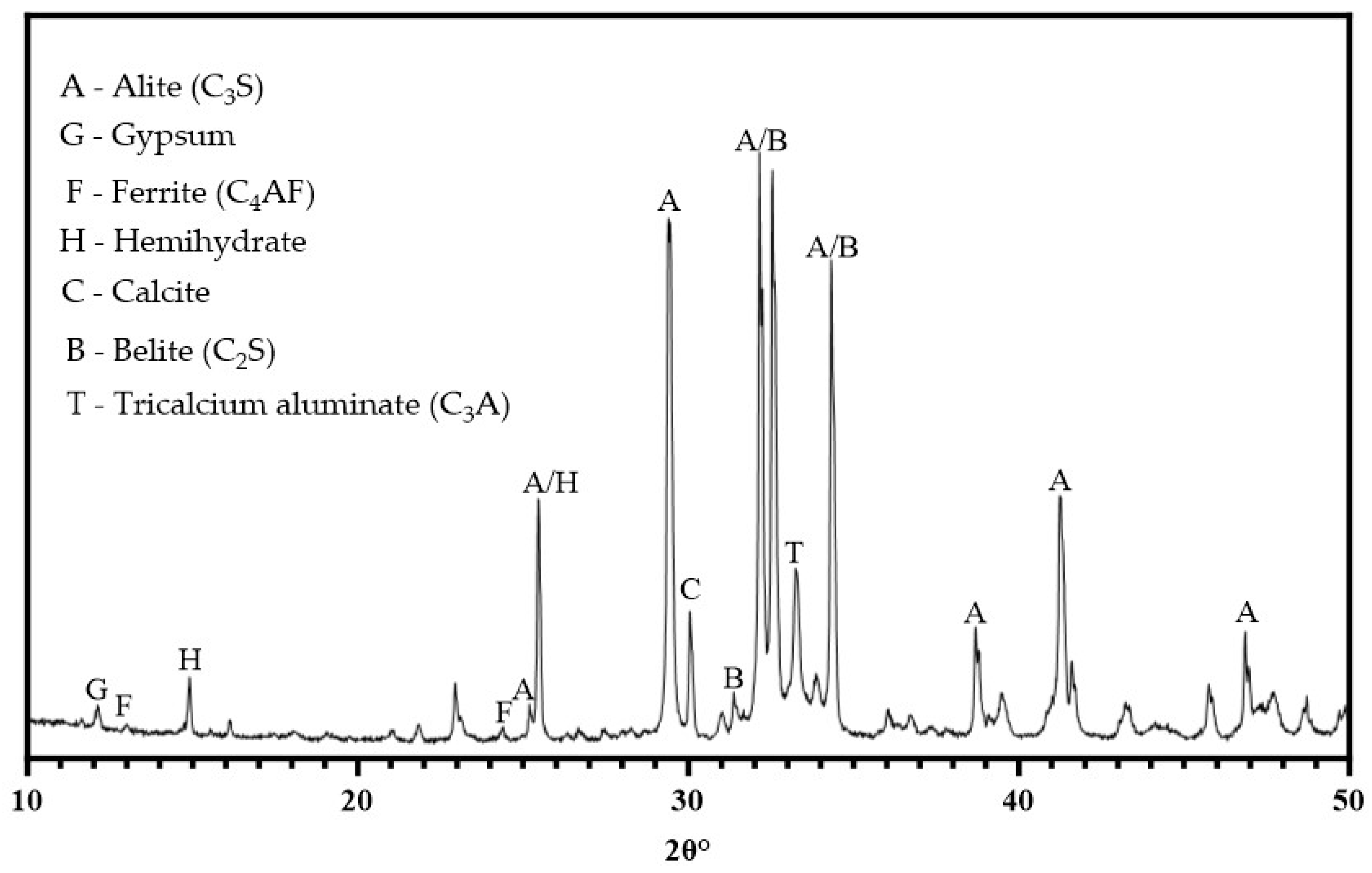
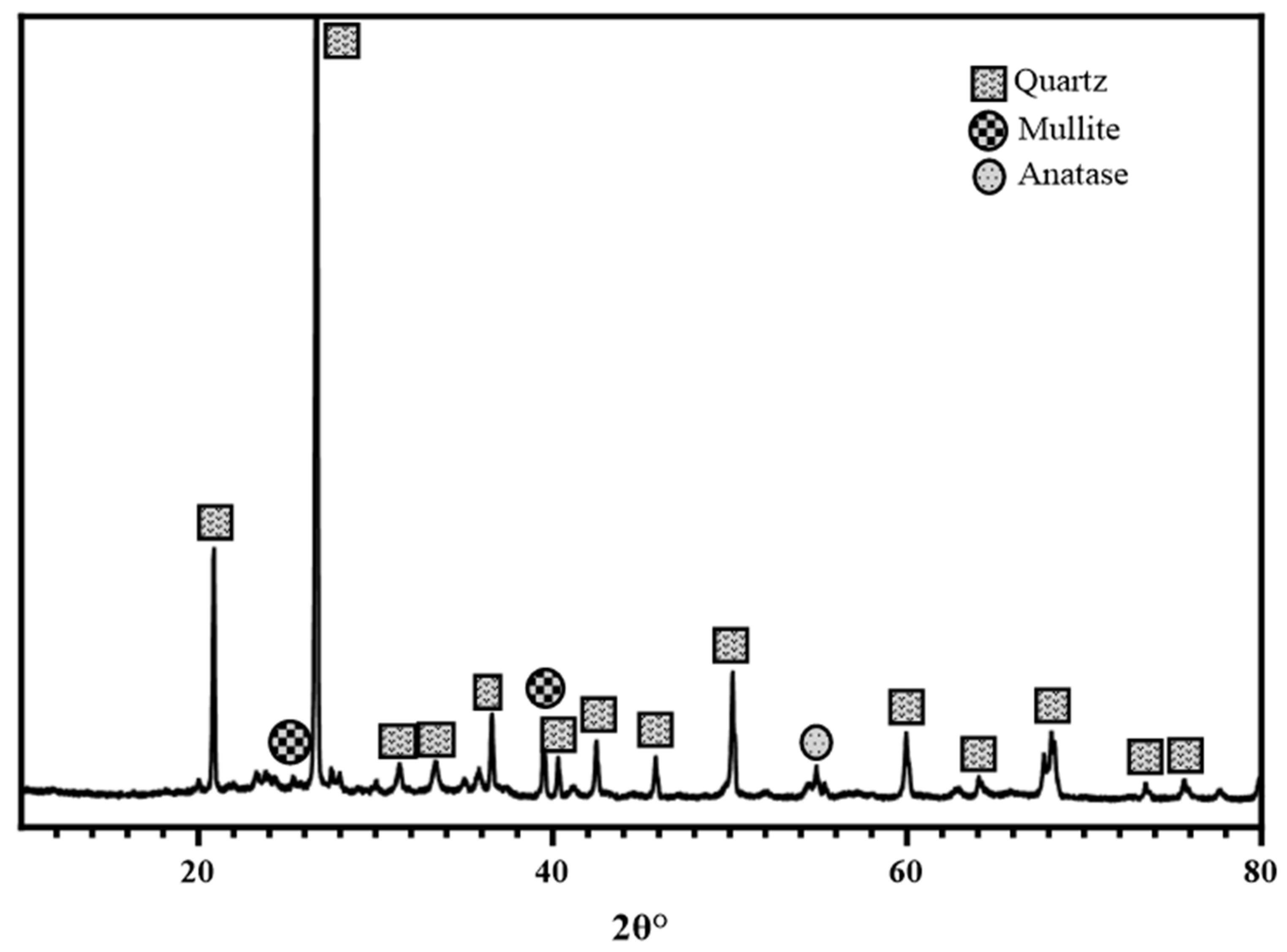
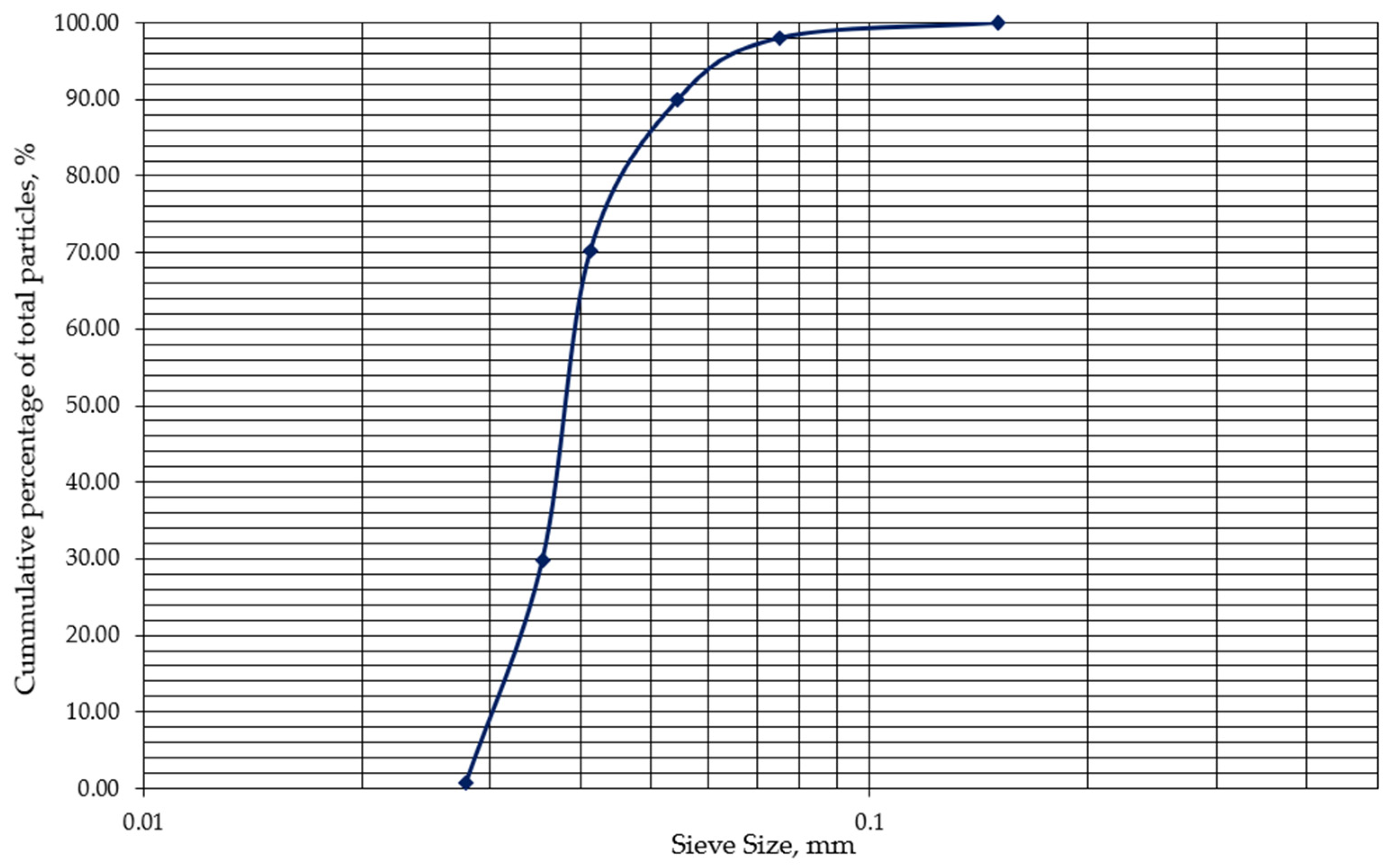
2.1. Materials

The primary binder used for all cement pastes and mortar specimens was high-strength (52.5 N) ordinary Portland cement conforming to EN 197-1 [19]. This cement had a specific gravity and Blaine fineness of 3.15 g/cm3 and 410 m2/kg, respectively, and a mineralogical composition of C3S—65.1%, C2S—14.3%, C3A—5.4%, and C4AF—7.8%. Calcined clay was produced by calcining clay with a kaolinite content of 17% at 900 °C and used to partially replace cement in varying weight percentages. The temperature of calcination was decided based on earlier studies [18,20]. The calcined clay was brick red in colour with a particle size less than 45 µm. Lower particle diameter is essential to facilitate pozzolanic reaction in the cement matrix. X-ray fluorescence (XRF) and X-ray diffraction (XRD) of the cement and calcined clay are shown in Table 1 and Figure 1, respectively. Sharp sand larger than 75 µm and finer than 4.5 mm was used as the fine aggregate for the mortar mixtures. The specific gravity of the sand was 3.64, and its moisture content was 0.26%. Additionally, it measured a 2.6% fineness modulus and a 3% silt content. Figure 2 and Figure 3 are the XRD and particle size distribution for the calcined clay, respectively.

2.2. Methods

The calcined clay blended cement samples were prepared by partially substituting CEM-I with calcined clay in proportions between 10 and 40%. A cement–sand ratio of 1:3 and water–cement ratio of 1:0.5 were used to prepare mortar cubes with dimensions 50 × 50 × 50 mm according to methods prescribed by EN 196-1 [21]. The compressive strength of the mortar specimens was determined after water-curing for 3, 7, 28 and 91 days.

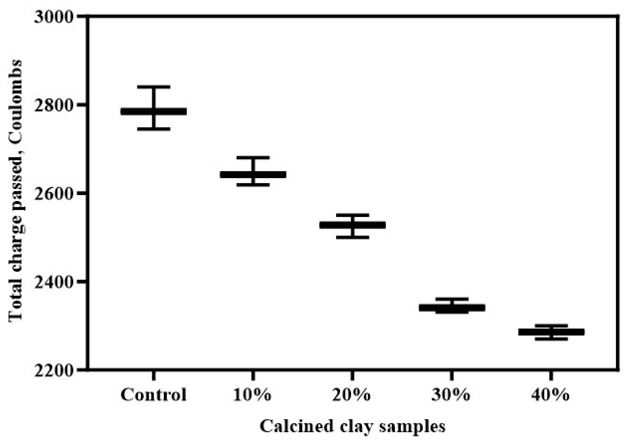
2.2.1. Rapid Chloride Penetration Test

The electrical conductivity of the mortar mixes was determined through an RCPT, following the guidelines outlined in ASTM C1202 [22], to gauge their resistance against chloride ion ingress. The specimens’ resistance to chloride ions was evaluated with respect to the total charge passed, measured in coulombs. For the RCPT, 100 mm diameter blended cement mortar cores were utilised, and electrical current measurements were recorded over a six-hour duration. One sample was placed in a solution of NaCl2, while the other was placed in a NaOH solution. The specimen ends were maintained at a potential difference of 60 V. Figure 4 is the RCPT setup.

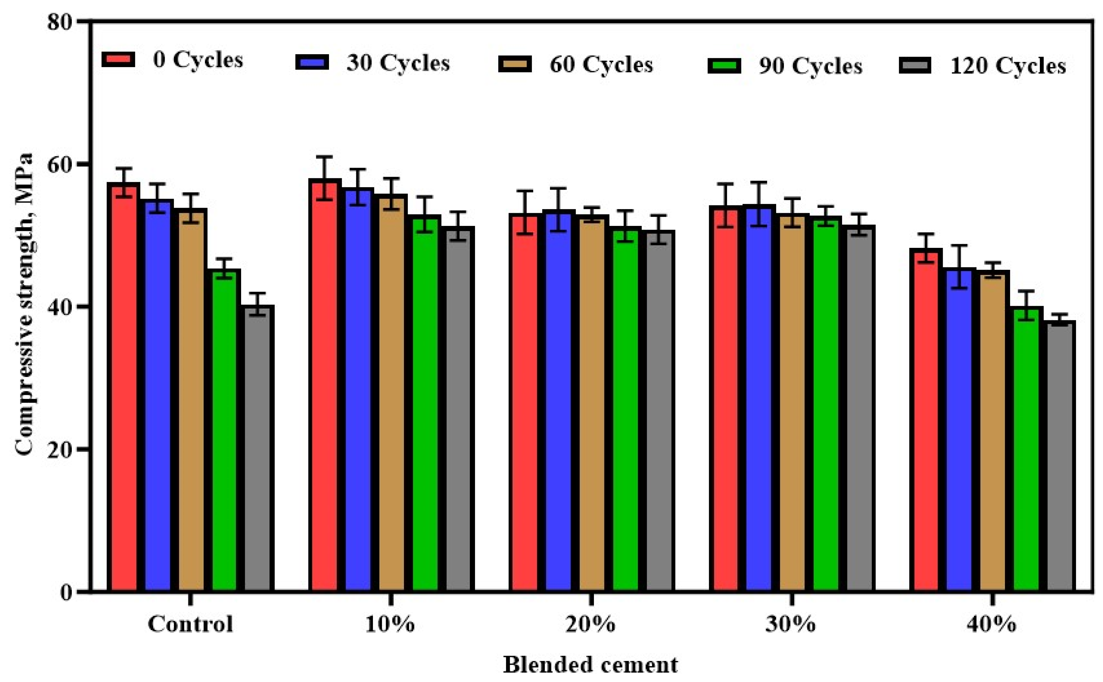
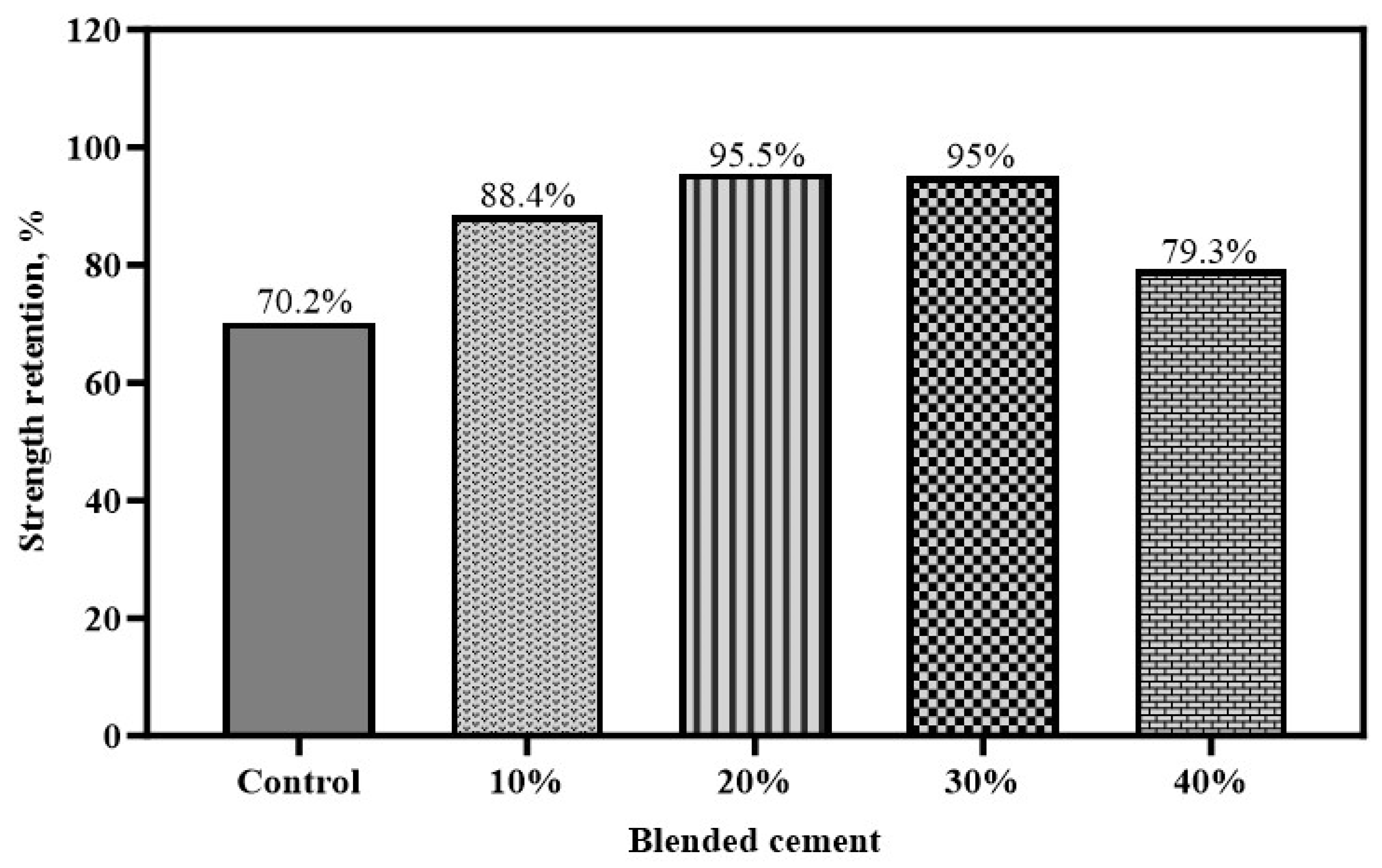
2.2.2. Freeze and Thaw Test

The freeze–thaw test was performed using a WEISS WKL 64 environmental chamber. The equipment is designed to mimic a strict, specific and accurate set of environmental conditions. Following their 28- and 91-day curing periods, the test specimens were put in the environmental chamber. The system was set to complete a total of 300 cycles, each cycle lasting for 7 h (420 min). The temperatures of the cycle ranged between 300 cycles of freezing at −19.8 °C and thawing at 4.5 °C. Humidity was maintained at 80%. Following the cycle, the effect of the entire process on the samples’ mass and strength was evaluated. Compressive strength retention was determined using Equation (1).
S t r e n g t h   r e t e n t i o n   ( % ) = C o m p r e s s i v e   s t r e n g t h   a f t e r   f r e e z e   a n d   t h a w I n i t i a l   c o m p r e s s i v e   s t r e n g t h × 100

2.2.3. Sorptivity and Permeable Porosity Test

The sorptivity coefficient was used to quantify the sorptivity of water, as recommended by ASTM C1585-13 [23]. After curing the samples for 3, 7, 27 and 91 days, they were dried in the oven until a consistent weight was achieved, as recommended by [24], and cooled to ambient temperature. The sides of the cube were smeared with epoxy to prevent water from entering through those surfaces. The samples were immersed in a pond of water such that one of the uncovered surfaces was in contact with the bottom of the pond to serve as the inflow. The weight of the samples was periodically taken during the test to calculate the quantity of water absorbed per unit inflow surface area (I). Water sorptivity was calculated employing Equation (1), where t represents the time elapsed since commencing the test, and k is the sorptivity coefficient. Permeable porosity was determined using methods outlined by ASTM C642-13 [25].
I = k t

2.2.4. Ultrasonic Pulse Velocity

A high UPV value is characteristic of a denser concrete with minimal porosity, whereas a low UPV value suggests a sample with numerous pores. Utilising UPV equipment, manufactured by Shimadzu, London, UK, the ultrasonic pulse velocity test was conducted by noting how long a pulse traverses across the opposing surfaces of the concrete. The ultrasonic transducers were set to frequencies of 1 kHz. The velocity is computed using Equation (3). Figure 5 illustrates the UPV setup.
Velocity (km/s) = Distance covered by the pulse

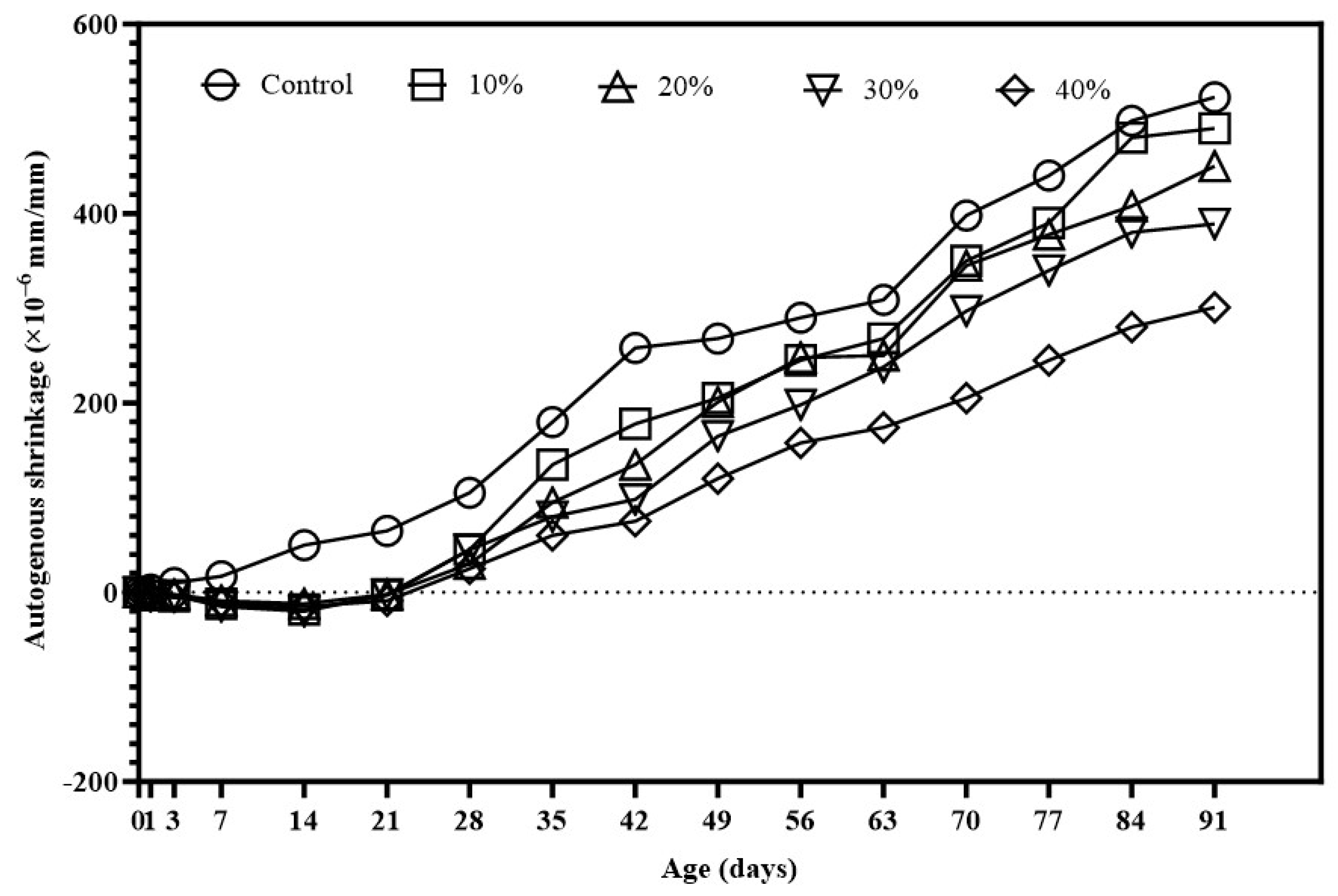
2.2.5. Autogenous Shrinkage

The autogenous shrinkage of mortar was determined using ASTM C490 [26]. Specimens were cast in 75 × 75 × 285 mm moulds. Following casting, the samples were covered with plastic film to stop moisture from evaporating, and they were kept at 20 ± 2 °C in a temperature-controlled curing chamber until testing. Subsequently, the specimens were cautiously extracted from the moulds and left to acclimate to ambient temperature. The length of each specimen was measured with a digital calliper. Autogenous shrinkage was determined as the alteration in specimen length over time, typically gauged at regular intervals, with the sample’s original length serving as reference. The findings were presented as the average autogenous shrinkage observed during the designated testing duration.

3. Results and Discussion

3.1. Sorptivity and Permeable Porosity

One limitation of concrete, despite its robust characteristics, is that it is not impervious to the ingress of moisture. The interaction between concrete and water is a critical consideration in the assessment of its long-term performance and durability. Two essential characteristics that significantly impact the transport of water through concrete are porosity and sorptivity [27]. Permeable porosity influences the overall transport properties of concrete, impacting its resistance to water penetration and the potential for deleterious effects [28].
The effect of calcined clay composition (0%, 10%, 20%, 30%, and 40%) on the sorptivity and permeable porosity of concrete, offering valuable insights into the calcined clay’s response to capillary absorption and fluid transport properties, is shown in Figure 6. Specimens marked control, 10%, 20%, 30% and 40% recorded sorptivity coefficients of 0.062 mm/s0.5, 0.058 mm/s0.5, 0.021 mm/s0.5, 0.016 mm/s0.5, and 0.012 mm/s0.5 respectively, exhibiting a notable trend as the percentage of calcined clay in the concrete increased. From 0% to 40%, the sorptivity values consistently decreased, improving the concrete’s resistance to absorption. The reduction in sorptivity is because of the pozzolanic reaction which enhances the microstructure of the concrete by decreasing the connectivity of capillary pores [29]. As calcined clay content increases, the internal structure becomes more refined, resulting in a denser matrix that effectively hinders water ingress [30]. The most significant reduction in sorptivity is observed between 20% and 40% calcined clay content. This suggests that beyond a certain threshold, the positive effects of calcined clay on capillary absorption become more pronounced, showcasing its potential to mitigate water permeation in a nonlinear manner.
Similarly to the sorptivity findings, the permeable porosity decreases as the calcined clay content increases. This reduction in permeable porosity indicates fewer interconnected voids within the concrete matrix, aligning with the microstructural refinement provided by calcined clay [31]. The pozzolanic reaction generates additional binding phases, further decreasing permeable porosity [32]. The most significant reduction occurs between 10% and 20% calcined clay content, suggesting this range is particularly effective in enhancing the concrete’s resistance to fluid penetration. Beyond 20%, the rate of reduction slows, indicating diminishing returns in further improving permeability.
The results obtained by the sorptivity and porosity investigation were due to the fine calcined clay particles which improved packing density, lowered the number of voids and refined the pores of the binder mix. This led to a substantial reduction in porosity and sorptivity [33].

3.2. Resistance to Freeze and Thaw

Freeze–thaw durability is a critical parameter in the assessment of concrete performance, especially in environments characterised by cyclic freezing and thawing conditions. Figure 7 demonstrates the impact of varying percentages of calcined clay (0%, 10%, 20%, 30%, and 40%) on the freeze–thaw resistance of concrete subjected to different cycles (0, 30, 60, 90, and 120 cycles). The compressive strength after each cycle is used as a key indicator to evaluate the concrete’s ability to resist the deleterious effects of freeze–thaw cycles.
It is observed that, as calcined clay content increased, there was a discernible trend of decreasing compressive strength after freeze–thaw cycles. This pattern is consistent across all cycle intervals. The control sample exhibited the highest compressive strength but experienced the most significant reduction with increasing freeze–thaw cycles. The control concrete recorded a compressive strength reduction of 4.1%, 12.9%, 27.0% and 29.7% after 30, 60, 90 and 120 freeze and thaw cycles, respectively. The addition of 10% calcined clay led to marginal reductions in compressive strength after freeze–thaw cycles. This range exhibits promising resistance, with reductions below 11% even after 120 cycles. A notable improvement in freeze–thaw resistance is observed with 20% calcined clay, where compressive strength reductions remain below 5% even after 120 cycles. When calcined clay percentage was raised to 30%, a balanced performance was recorded, showcasing relatively low compressive strength reductions, with enhancements in freeze–thaw resistance, especially up to 90 cycles. While still providing improvements, concrete with 40% calcined clay exhibited higher compressive strength reductions, indicating a potential saturation point beyond which the benefits diminish.
An increase in the number of freeze–thaw cycles is associated with a predicted fall in compressive strength for all calcined clay replacements. This decline reflected the cumulative damage inflicted on the concrete due to repeated freeze–thaw actions. Concrete mixtures with higher calcined clay content exhibited a gradual decrease in strength in contrast to the reference. This suggests that the presence of calcined clay contributes to mitigating the adverse effects of freeze and thaw on compressive strength. This is due to the improvement of pore structure and reduction in porosity. This denser microstructure limits water ingress, reducing the risk of freezing and internal cracking during freeze–thaw cycles [31]. Additionally, calcined clay reacts with calcium hydroxide to form C-A-S-H phases, enhancing the binding and stability of the paste. These improvements strengthen the concrete and reduce the formation of microcracks, further increasing its resistance to freeze and thaw damage [34].
It is also observed that concrete specimens containing 10% and 20% calcined clay exhibited more resilient strength profiles at different cycle intervals. Compressive strength decreased more sharply over 20% calcined clay, suggesting a possible saturation or declining returns. This emphasises how crucial it is to use the right amount of calcined clay to maximise freeze–thaw resistance.
Figure 8 displays the capacity of each sample to maintain or preserve its compressive strength after undergoing 120 cycles of freeze and thaw. The strength retention values vary with the percentage of calcined clay in the concrete mixtures after 120 freeze–thaw cycles. Concrete with 10% and 20% calcined clay exhibits high strength retention values of 88.4% and 95.5%, respectively, suggesting these mixtures retain a significant proportion of their compressive strength. The samples with 0%, 30%, and 40% calcined clay display strength retention values of 70.2%, 95%, and 79.3%, respectively. The concrete mixture with 20% calcined clay demonstrates the highest strength retention at 95.5%. This indicates that, among the tested compositions, the 20% calcined clay content provides the most effective enhancement of strength retention after exposure to 120 freeze–thaw cycles.
The diminishing strength retention in the 40% calcined clay sample suggests potential saturation effects. Beyond a certain threshold, the benefits derived from calcined clay may reach a plateau, and further increases in percentage may not proportionally enhance strength retention. The 20% calcined clay sample demonstrates an optimal dosage, balancing the positive effects of pozzolanic reactivity with potential limitations at higher concentrations. It therefore emerges as an optimal choice for achieving the desired balance between strength and durability.
The higher strength retention in concrete containing calcined clay is attributed to its pozzolanic activity, which promotes the formation of additional hydration products. This improved microstructure reduces porosity and limits water ingress, thereby minimising freeze–thaw-induced damage and enhancing strength retention. In contrast, the control mixes exhibit a greater decline in strength due to freeze–thaw-induced microcracking in the concrete matrix. The pozzolanic reactivity of calcined clay leads to microstructural refinement by generating additional binding phases, which improve resistance to freeze–thaw deterioration [34]. The superior freeze–thaw resistance of blended cement mixes is primarily due to their refined pore structure and lower overall porosity compared to the reference mixtures [35]. This results in reduced internal expansion forces and greater resilience against freeze–thaw cycles [36]. Similar findings have been reported in previous studies [37,38,39].

3.3. Chloride Permeability

The rapid chloride penetration test (RCPT) is used to assess concrete’s resistance to chloride ion penetration. Typically, a lower amount of charge passed indicates better resistance to chloride penetration. In RCPT, charges typically falling within the range of 1500 to 3000 coulombs are commonly categorised as indicative of relatively low chloride ion penetration, while charges below the threshold of 1500 coulombs are regarded as reflecting a moderate level of chloride ion penetration [40].
Despite facing several criticisms, RCPT remains a commonly used method to assess concrete’s resistance to chloride. Figure 9 illustrates the resistance of both reference and blended cement concrete to chloride ingress. In concrete mixtures, the total charge passed reduced as the quantity of calcined clay increased. Concrete samples containing 0%, 10%, 20%, 30%, and 40% calcined clay exhibited total charges passed of 2787.3, 2643.9, 2531.3, 2339.7, and 2283.4 coulombs, respectively. The pozzolanic activity of calcined clay is responsible for the decrease in total charge passed with increased calcined clay content. Calcined clay creates more hydration products when combined with calcium hydroxide in the presence of water, giving the mixture a more refined microstructure, characterised by enhanced homogeneity, finer grain size, and increased densification [41]. The enhanced microstructure incorporates by-products of the pozzolanic reaction that occupy voids and pores, decreasing the permeability of the concrete. This restricts the movement of chloride ions, leading to a reduced total charge passed [42].
The observed trend of diminishing returns in the reduction in total charge passed with increasing percentages of calcined clay suggests a potential dilution effect as higher dosages are employed. This phenomenon implies that beyond a certain threshold, the pozzolanic reaction between calcined clay and the cementitious matrix achieves saturation, thereby constraining further improvements in the material’s microstructure. Optimal reduction in chloride permeability is achieved within the 20–30% range of calcined clay dosage, where the decline in total charge passed is most pronounced. This dosage range strikes an effective balance between leveraging the beneficial properties of calcined clay and mitigating potential limitations associated with higher replacement levels.

3.4. Autogenous Shrinkage

One of the difficulties faced in the application of concrete is autogenous shrinkage, a phenomenon characterised by the inherent volume change in concrete due to self-desiccation and self-drying processes [43]. Autogenous shrinkage can lead to cracking, affecting the structural integrity and long-term performance of concrete structures [44]. Figure 10 presents the influence of the calcined clay on autogenous shrinkage. Measurements were taken over a period of 91 days.
A clear trend is generally noticed across all the mixtures. The inclusion of calcined clay influenced the autogenous shrinkage behaviour of both the control and blended cement concrete throughout the study period. The control mixture experienced a steady increase in shrinkage, while the mixtures with calcined clay exhibited different patterns of shrinkage, often deviating from the control. During the initial days (up to 7 days), all mixtures showed a negligible or minimal level of shrinkage. The 10% calcined clay mixture initially exhibited some negative shrinkage, which could be attributed to early microstructural changes or measurement uncertainties. As the curing period progressed towards 28 days, the control mixture experienced a gradual increase in shrinkage, while mixtures with calcined clay generally show a mitigating effect on shrinkage. The 10% calcined clay mixture continued to display some negative shrinkage, suggesting a potential influence of calcined clay on early-age shrinkage. Beyond 28 days, a more distinct pattern emerged. The mixtures with calcined clay showed reduced shrinkage compared to the control. The 20%, 30%, and 40% calcined clay mixtures consistently demonstrated a suppressive effect on shrinkage, with the 40% mixture demonstrating the most pronounced reduction.
The reduction in shrinkage observed in mixtures with calcined clay is attributed to the pozzolanic reactivity of calcined clay. The pozzolanic reaction consumes excess water and produces additional hydration products, leading to a refined microstructure with reduced porosity [45]. This, in turn, limits the potential for autogenous shrinkage. The 40% calcined clay mixture exhibits significant shrinkage reduction but also shows signs of diminishing returns.

3.5. Ultrasonic Pulse Velocity

Ultrasonic Pulse Velocity (UPV) is a non-destructive testing method widely used to assess the quality and integrity of concrete structures. UPV is a crucial indicator of concrete quality, providing insights into various properties such as density, elasticity, and overall integrity [46]. This non-destructive method is especially important for evaluating the internal conditions of concrete units, including detecting voids, cracks, or other anomalies that may compromise structural performance. UPV measurements are instrumental in quality control during construction, as well as in assessing the durability of existing structures [47].
Acceptable UPV values change based on the properties of the concrete and the structure’s intended application. In general, higher UPV values indicate denser and more homogeneous concrete, suggesting better quality and durability. Acceptance criteria often depend on factors such as concrete strength, age, and environmental conditions. For normal structural concrete, typical UPV values range from 3500 to 5000 m/s. However, it is essential to establish specific acceptance criteria based on the project requirements and local standards.
Figure 11 illustrates the UPV measurements conducted on concrete specimens incorporating varying percentages of calcined clay (ranging from 10% to 40%) and subjected to a 28-day curing period. 28 days was selected because it is the standard benchmark for evaluating the performance of concrete in terms of hydration and compressive strength, offering a practical and reliable timeframe for testing and quality assurance purposes.
The pozzolanic reactivity of calcined clay may be responsible for the observed trend of rising UPV with increasing calcined clay concentration. With an increase in the calcined clay content, more hydration products are generated through the pozzolanic reaction with calcium hydroxide. This process contributes to microstructural refinement and reduces porosity, resulting in a more homogenous and denser concrete matrix [48]. The increase in UPV with higher calcined clay content also suggests a densification effect. The refined microstructure, with fewer voids and better interlocking calcined clay particles, facilitates the transmission of ultrasonic pulses at a higher velocity [49]. This phenomenon aligns with the general understanding that increased concrete density leads to higher UPV values. Again, the increased UPV values are indicative of enhanced elasticity in concrete containing higher percentages of calcined clay. The pozzolanic reaction contributes to a more robust and flexible matrix, allowing ultrasonic waves to propagate more efficiently [50].

4. Conclusions

This investigation has studied the durability of mortar mixes containing low-grade calcined clay in varying proportions, and the following conclusions were drawn:
The introduction of low-grade calcined clay into the concrete mixtures resulted in a substantial decrease in both sorptivity and permeable porosity. This reduction signifies a positive influence on the concrete’s ability to resist water ingress and related deteriorative mechanisms. The filling of voids and reduction in the connectivity of capillary pores enhanced the concrete’s resistance to water ingress. Optimal reduction was observed between 20% and 40% calcined clay, indicating a nonlinear relationship.
The impact of calcined clay content on concrete’s resistance to freeze–thaw cycles was evident in the compressive strength variations observed after exposure to different freeze–thaw cycles. This durability parameter is crucial for structures exposed to cyclic freezing and thawing conditions. Compressive strength reductions after cycles were mitigated with calcined clay, showcasing enhanced freeze–thaw durability. This indicates improved resistance to the deleterious effects of freezing and thawing on concrete, highlighting the potential of calcined clay in enhancing freeze–thaw durability. Strength retention after 120 cycles highlighted the superior performance of 20% calcined clay. The optimised inclusion of calcined clay, particularly within the 10–20% range, provides an effective strategy for mitigating the detrimental effects of cyclic freeze and thaw actions on compressive strength. This provides valuable insights for designing durable and sustainable concrete structures in environments prone to cyclic freezing and thawing.
RCPT results demonstrated a decrease in total charge passed with increased calcined clay content, signifying improved resistance to chloride ion penetration as the composition of calcined clay increased. The most effective reduction in total charge passed, indicating improved chloride resistance, was observed within the range of 20–30% calcined clay. This suggests a balance between the positive effects of calcined clay and potential limitations at higher replacement levels.
The findings of the autogenous shrinkage test suggest that incorporating calcined clay in concrete mixtures has the potential to mitigate excessive volume change. The observed trends align with the expected benefits of pozzolanic materials in enhancing the microstructure and reducing shrinkage.
UPV measurements demonstrated an increase with higher calcined clay content, suggesting improved density and homogeneity of the concrete matrix. Densification effect and improved elasticity were noted in calcined clay blended cement concrete samples, aligning with refined microstructure and reduced porosity. As a result, the concrete becomes more robust and flexible, capable of withstanding deformation and stress without permanent damage, thus contributing to its improved mechanical properties and durability. The optimum increase in UPV was observed at 20% calcined clay, indicating a balance between the positive effects of pozzolanic reactivity and potential limitations at higher percentages. This suggests that 20% calcined clay provides an effective enhancement of UPV without encountering diminishing returns.
The incorporation of up to 20% low-grade calcined clay resulted in significant improvements in durability properties, including reductions in sorptivity, permeable porosity, chloride ion penetration, and freeze and thaw. These improvements in durability translate to extended service life and reduced maintenance requirements for concrete structures. The findings of this study highlight the significant potential of low-grade calcined clays as a viable alternative to high-grade calcined clays and metakaolin in concrete production. Given their comparable and superior performance in durability and strength retention, low-grade calcined clays can be effectively utilised in infrastructure projects requiring enhanced durability, such as bridge decks, pavements and marine structures exposed to aggressive environments. Further microstructural studies are, however, required to understand the interplay between the calcined clay particles and cement in the mortar matrix.

Author Contributions

Conceptualization, M.K.; Methodology, M.K.; Investigation, M.K.; Writing—original draft, K.B.; Writing—review & editing, K.B. All authors have read and agreed to the published version of the manuscript.

Funding

This research received no external funding.

Data Availability Statement

The original contributions presented in the study are included in the article, further inquiries can be directed to the corresponding author.

Conflicts of Interest

The authors declare no conflict of interest.

References

  1. Juenger, M.C.G.; Snellings, R.; Bernal, S.A. Supplementary cementitious materials: New sources, characterization, and performance insights. Cem. Concr. Res. 2019, 122, 257–273. [Google Scholar] [CrossRef]
  2. Aghamohammadi, O.; Mostofinejad, D.; Mostafaei, H.; Abtahi, S.M. Mechanical properties and impact resistance of concrete pavement containing crumb rubber. Int. J. Geomech. 2024, 24, 04023242. [Google Scholar] [CrossRef]
  3. Aprianti, S.E. A huge number of artificial waste material can be supplementary cementitious material (SCM) for concrete production—A review part II. J. Clean. Prod. 2017, 142, 4178–4194. [Google Scholar] [CrossRef]
  4. Sarfo-Ansah, J.; Atiemo, E.; Bediako, M.; Tagbor, T.A.; Boakye, K.A.; Adjei, D. The influence of calcined clay pozzolan, low-CaO steel slag and granite dust on the alkali-silica reaction in concrete. J. Eng. Res. Appl. 2015, 5, 19–27. [Google Scholar]
  5. Emmanuel, A.C.; Bishnoi, S. Effect of curing temperature and clinker content on hydration and strength development of calcined clay blends. Adv. Cem. Res. 2023, 35, 12–25. [Google Scholar] [CrossRef]
  6. Fernandez, R.; Martirena, F.; Scrivener, K.L. The origin of the pozzolanic activity of calcined clay minerals: A comparison between kaolinite, illite and montmorillonite. Cem. Concr. Res. 2011, 41, 113–122. [Google Scholar] [CrossRef]
  7. Scrivener, K.; Martirena, F.; Bishnoi, S.; Maity, S. Calcined clay limestone cements (LC3). Cem. Concr. Res. 2018, 114, 49–56. [Google Scholar] [CrossRef]
  8. Kijjanon, A.; Sumranwanich, T.; Tangtermsirikul, S. Influences of metakaolin and calcined clay blended cement on chloride resistance and electrical resistivity of concrete. Adv. Cem. Res. 2024, 37, 24–37. [Google Scholar] [CrossRef]
  9. Shah, V.; Parashar, A.; Mishra, G.; Medepalli, S.; Krishnan, S.; Bishnoi, S. Influence of cement replacement by limestone calcined clay pozzolan on the engineering properties of mortar and concrete. Adv. Cem. Res. 2020, 32, 101–111. [Google Scholar] [CrossRef]
  10. Hollanders, S.; Adriaens, R.; Skibsted, J.; Cizer, Ö.; Elsen, J. Pozzolanic reactivity of pure calcined clays. Appl. Clay. Sci. 2016, 132–133, 552–560. [Google Scholar] [CrossRef]
  11. Tagbor, T.A.; Boakye, K.A.; Sarfo-Ansah, J.; Atiemo, E. A study of the pozzolanic properties of Anfoega Kaolin. Int. J. Eng. Res. Appl. 2015, 5, 28–33. [Google Scholar]
  12. Avet, F.; Scrivener, K. Investigation of the calcined kaolinite content on the hydration of Limestone Calcined Clay Cement (LC3). Cem. Concr. Res. 2018, 107, 124–135. [Google Scholar]
  13. Boakye, K.; Khorami, M. Hydration, Reactivity and Durability Performance of Low-Grade Calcined Clay-Silica Fume Hybrid Mortar. Appl. Sci. 2023, 13, 11906. [Google Scholar] [CrossRef]
  14. Beuntner, N.; Thienel, K. Pozzolanic efficiency of calcined clays in blended cements with a focus on early hydration. Adv. Cem. Res. 2022, 34, 341–355. [Google Scholar]
  15. Zhou, D.; Wang, R.; Tyrer, M.; Wong, H.; Cheeseman, C. Sustainable infrastructure development through use of calcined excavated waste clay as a supplementary cementitious material. J. Clean. Prod. 2017, 168, 1180–1192. [Google Scholar]
  16. Zheng, D.; Liang, X.; Cui, H.; Tang, W.; Liu, W.; Zhou, D. Study of performances and microstructures of mortar with calcined low-grade clay. Constr. Build. Mater. 2022, 327, 126963. [Google Scholar]
  17. Dixit, A.; Du, H.; Pang, S.D. Marine clay in ultra-high performance concrete for filler substitution. Constr. Build. Mater. 2020, 263, 120250. [Google Scholar]
  18. Boakye, K.; Khorami, M.; Saidani, M.; Ganjian, E.; Dunster, A.; Tyrer, M.; Ehsani, A. Influence of Calcining Temperature on the Mineralogical and Mechanical Performance of Calcined Impure Kaolinitic Clays in Portland Cement Mortars. J. Mater. Civ. Eng. 2024, 36, 04024040. [Google Scholar]
  19. BS EN 197-1; Cement, Composition, Specifications and Conformity Criteria for Common Cements. British Standard Institution: London, UK, 2011.
  20. Boakye, K.; Khorami, M.; Saidani, M.; Ganjian, E.; Dunster, A.; Ehsani, A.; Tyrer, M. Mechanochemical characterisation of calcined impure kaolinitic clay as a composite binder in cementitious mortars. J. Compos. Sci. 2022, 6, 134. [Google Scholar] [CrossRef]
  21. BS EN 196-1; Methods of Testing Cement. Determination of Strength. British Standard Institution: London, UK, 2016.
  22. ASTM C1202; Standard Test Method for Electrical Indication of Concrete’s Ability to Resist Chloride Ion Penetration. ASTM International: West Conshohocken, PA, USA, 2018.
  23. ASTM C1585-13; Standard Test Method for Measurement of Rate of Absorption of Water by Hydraulic-Cement Concretes. ASTM International: West Conshohocken, PA, USA, 2020.
  24. Ramachandran, V.S.; Beaudoin, J.J. Handbook of Analytical Techniques in Concrete Science and Technology, Principles, Techniques and Applications; Elsevier: Amsterdam, The Netherlands, 2000. [Google Scholar]
  25. ASTM C642-13; Standard Test Method for Density, Absorption, and Voids in Hardened Concrete. ASTM International: West Conshohocken, PA, USA, 2022.
  26. ASTM C490; Standard Practice for Use of Apparatus for the Determination of Length Change of Hardened Cement Paste, Mortar, and Concrete. ASTM International: West Conshohocken, PA, USA, 2010.
  27. Bamigboye, G.O.; Ademola, D.; Kareem, M.; Orogbade, B.; Odetoyan, A.; Adeniyi, A. 20-Durability assessment of recycled aggregate in concrete production. In The Structural Integrity of Recycled Aggregate Concrete Produced with Fillers and Pozzolans; Awoyera, P.O., Thomas, C., Kirgiz, M.S., Eds.; Woodhead Publishing: Cambridge, UK, 2022; pp. 445–467. [Google Scholar]
  28. Safiuddin, M.; Hearn, N. Comparison of ASTM saturation techniques for measuring the permeable porosity of concrete. Cem. Concr. Res. 2005, 35, 1008–1013. [Google Scholar]
  29. Güneyisi, E.; Mermerdaş, K. Comparative study on strength, sorptivity, and chloride ingress characteristics of air-cured and water-cured concretes modified with metakaolin. Mater. Struct. 2007, 40, 1161–1171. [Google Scholar] [CrossRef]
  30. Tironi, A.; Sposito, R.; Cordoba, G.P.; Zito, S.V.; Rahhal, V.F.; Thienel, K.C.; Irassar, E. Influence of different calcined clays on the water transport performance of concretes. Mag. Concr. Res. 2022, 74, 702–714. [Google Scholar] [CrossRef]
  31. Dhandapani, Y.; Santhanam, M. Investigation on the microstructure-related characteristics to elucidate performance of composite cement with limestone-calcined clay combination. Cem. Concr. Res. 2020, 129, 105959. [Google Scholar] [CrossRef]
  32. Shekarchi, M.; Bonakdar, A.; Bakhshi, M.; Mirdamadi, A.; Mobasher, B. Transport properties in metakaolin blended concrete. Constr. Build. Mater. 2010, 24, 2217–2223. [Google Scholar] [CrossRef]
  33. Chen, J.J.; Ng, P.L.; Chu, S.H.; Guan, G.X.; Kwan, A.K.H. Ternary blending with metakaolin and silica fume to improve packing density and performance of binder paste. Constr. Build. Mater. 2020, 252, 119031. [Google Scholar] [CrossRef]
  34. Sarıdemir, M.; Çiflikli, M.; Soysat, F. Mechanical and microstructural properties of HFRHSCs containing metakaolin subjected to elevated temperatures and freezing-thawing cycles. Constr. Build. Mater. 2018, 158, 11–23. [Google Scholar] [CrossRef]
  35. Yan, D.; Xie, L.; Qian, X.; Ruan, S.; Zeng, Q. Compositional dependence of pore structure, strengthand freezing-thawing resistance of metakaolin-based geopolymers. Materials 2020, 13, 2973. [Google Scholar] [CrossRef]
  36. Nas, M.; Kurbetci, S. Durability properties of concrete containing metakaolin. Adv. Concr. Constr. 2018, 6, 159. [Google Scholar]
  37. Qin, Z.; Ma, C.; Zheng, Z.; Long, G.; Chen, B. Effects of metakaolin on properties and microstructure of magnesium phosphate cement. Constr. Build. Mater. 2020, 234, 117353. [Google Scholar] [CrossRef]
  38. Kalkan, E. Effects of silica fume on the geotechnical properties of fine-grained soils exposed to freeze and thaw. Cold Reg. Sci. Technol. 2009, 58, 130–135. [Google Scholar] [CrossRef]
  39. Sabir, B.B. Mechanical properties and frost resistance of silica fume concrete. Cem. Concr. Compos. 1997, 19, 285–294. [Google Scholar]
  40. Dhandapani, Y.; Sakthivel, T.; Santhanam, M.; Gettu, R.; Pillai, R.G. Mechanical properties and durability performance of concretes with Limestone Calcined Clay Cement (LC3). Cem. Concr. Res. 2018, 107, 136–151. [Google Scholar]
  41. Ramezanianpour, A.A.; Bahrami Jovein, H. Influence of metakaolin as supplementary cementing material on strength and durability of concretes. Constr. Build. Mater. 2012, 30, 470–479. [Google Scholar] [CrossRef]
  42. Gill, A.S.; Siddique, R. Durability properties of self-compacting concrete incorporating metakaolin and rice husk ash. Constr. Build. Mater. 2018, 176, 323–332. [Google Scholar]
  43. Mermerdaş, K.; Arbili, M.M. Explicit formulation of drying and autogenous shrinkage of concretes with binary and ternary blends of silica fume and fly ash. Constr. Build. Mater. 2015, 94, 371–379. [Google Scholar]
  44. Gao, X.; Kawashima, S.; Liu, X.; Shah, S.P. Influence of clays on the shrinkage and cracking tendency of SCC. Cem. Concr. Compos. 2012, 34, 478–485. [Google Scholar]
  45. Alujas, A.; Fernández, R.; Quintana, R.; Scrivener, K.L.; Martirena, F. Pozzolanic reactivity of low grade kaolinitic clays, Influence of calcination temperature and impact of calcination products on OPC hydration. Appl. Clay Sci. 2015, 108, 94–101. [Google Scholar] [CrossRef]
  46. Sui, S.; Wilson, W.; Georget, F.; Maraghechi, H.; Kazemi-Kamyab, H.; Sun, W.; Scrivener, K. Quantification methods for chloride binding in Portland cement and limestone systems. Cem. Concr. Res. 2019, 125, 105864. [Google Scholar]
  47. Chandak, M.A.; Pawade, P. Compressive Strength and Ultrasonic Pulse Velocity of Concrete with Metakaolin. Civ. Eng. Archit. 2020, 8, 1277–1282. [Google Scholar]
  48. Kannan, V. Relationship between ultrasonic pulse velocity and compressive strength of self compacting concrete incorporate rice husk ash and metakaolin. Asian J. Civ. Eng. 2015, 16, 1077–1088. [Google Scholar]
  49. Malagavelli, V.; Angadi, S.; Prasad, J.; Joshi, S. Influence of metakaolin in concrete as partial replacement of cement. Int. J. Civil. Eng. Technol. 2018, 9, 105–111. [Google Scholar]
  50. Saand, A.; Keerio, M.A.; Khan BANGWAR, D. Effect of metakaolin developed from local natural material soorh on workability, compressive strength, ultrasonic pulse velocity and drying shrinkage of concrete. Archit. Civ. Eng. Environ. 2017, 10, 115–122. [Google Scholar]
Figure 1. XRD of cement.
Buildings 15 01159 g001
Figure 2. XRD of calcined clay.
Buildings 15 01159 g002
Figure 3. Particle size distribution of calcined clay.
Buildings 15 01159 g003
Figure 4. Setup for rapid chloride permeability test.
Buildings 15 01159 g004
Figure 5. Ultrasonic pulse velocity test.
Buildings 15 01159 g005
Figure 6. Sorptivity and permeable porosity of blended cement concrete samples.
Buildings 15 01159 g006
Figure 7. Effect of freeze and thaw on compressive strength.
Buildings 15 01159 g007
Figure 8. Strength retention of blended cement samples after 120 freeze and thaw cycles.
Buildings 15 01159 g008
Figure 9. RCPT—total charge passed in the blended cement concrete samples.
Buildings 15 01159 g009
Figure 10. Autogenous shrinkage in blended cement concrete.
Buildings 15 01159 g010
Figure 11. Ultrasonic pulse velocity of blended cement concrete.
Buildings 15 01159 g011
Table 1. Elemental composition of cement and calcined clay.
Composition, %SiO2Al2O3Fe2O3MgOCaONa2OK2OMnOTiO2P2O5ClSO3
Calcined clay64.2318.6510.541.740.350.041.50.480.410.010.16
OPC18.753.682.581.8562.183.142.10.110.180.210.012.75
Disclaimer/Publisher’s Note: The statements, opinions and data contained in all publications are solely those of the individual author(s) and contributor(s) and not of MDPI and/or the editor(s). MDPI and/or the editor(s) disclaim responsibility for any injury to people or property resulting from any ideas, methods, instructions or products referred to in the content.

