Article

Numerical Response of Advance Support Structures in TBM Tunneling Through Altered Zones: A Case Study

1
State Key Laboratory of Intelligent Geotechnics and Tunnelling, Southwest Jiaotong University, Chengdu 610031, China
2
China Railway Eryuan Engineering Group Co., Ltd., Chengdu 610031, China
3
Yungui Railway Yunnan Co., Ltd., Kunming 650011, China
*
Authors to whom correspondence should be addressed.
Buildings 2025, 15(4), 509; https://doi.org/10.3390/buildings15040509
Submission received: 19 December 2024 / Revised: 4 February 2025 / Accepted: 5 February 2025 / Published: 7 February 2025
(This article belongs to the Section Building Structures)

Abstract

Tunnel Boring Machines (TBMs) play a vital role in modern tunnel construction due to their efficiency and adaptability across various geological conditions. However, when tunneling through geologically altered zones, such as fault zones and soft ground, significant challenges arise, including increased wear, reduced advance rates, and heightened safety risks. This study explores advanced support measures for TBM excavation in altered zones, focusing on deformation characteristics and the bearing capacity of different support strategies in both normal and altered rock masses. Through numerical simulations on the FLAC3D platform, we compare the stress distribution and disturbance evolution in the surrounding rock with and without pre-reinforcement, as well as with single-layer and double-layer pipe-shed supports. The findings reveal that a lack of advance support leads to severe surrounding rock instability and an increased risk of TBM jamming. While single-layer pipe roofing offers partial mitigation, its limited stiffness constrains its effectiveness. In contrast, double-layer large pipe roofing provides superior bending stiffness, effectively minimizing settlement and deformation while significantly reducing the likelihood of TBM jamming. These findings offer practical guidance for the design and implementation of robust TBM support systems, enhancing tunneling safety and efficiency in complex geological conditions.

1. Introduction

Tunnel Boring Machines (TBMs) have become integral to modern tunnel construction due to their efficiency and adaptability across various ground conditions. In recent years, TBM technology has rapidly gained traction in sectors such as railway, highway, mining, water conservancy, hydropower, and municipal engineering, largely due to its speed, quality, mechanization, and safety benefits [1,2,3,4,5,6,7,8,9,10]. However, as TBM applications expand into geologically complex terrains, such as fault zones and altered rock masses, new technical challenges emerge that complicate both construction efficiency and safety. Major challenges arise from the geological variability in altered zones. Excavating through these zones often leads to increased machine wear, slower advance rates, and heightened safety risks [11,12,13,14,15]. For instance, in the Qinling water diversion tunnel of the Hanjiang-to-Weihe River Project, which passes through extremely hard granite, frequent cutter replacements were required, with inspection of the cutter head and cutter replacement accounting for 19.2% of the total construction time [16]. The collapse of the Zagros water transmission tunnel in Iran, caused by water-bearing fault zones and compressed formations, resulted in an eight-month TBM stoppage [17]. The Turkish diversion tunnel also experienced 18 TBM disruptions due to compressed formations, requiring 192 days to resolve [18]. The TBM excavation of the headrace tunnel for the Dul Hasti Hydropower Station took nearly 12 years to complete after experiencing several incidents of water and mud inrush [19,20].
The primary factor contributing to these challenges lies in the mechanical and mineralogical changes caused by rock alteration. Altered rock masses, such as those observed in weathered granite and tuff formations, exhibit reduced strength and stiffness due to changes in mineral composition and pore structures [21], a phenomenon that not only increases the likelihood of deformation and instability but also elevates the risk of geological disasters such as water inrush and mudflows [22,23]. For example, swelling clays within altered granite can lead to non-uniform deformations, imposing additional loads on support structures and compromising their performance under high-stress conditions [24].
Although TBM technology has advanced significantly, traditional support measures often fail to address the complexities of altered geological conditions. Common challenges include limited adaptability, uncertain effectiveness, and high costs, which extend construction timelines and compromise safety [25]. Existing studies have explored various advanced support techniques—including pipe roofing, grouting, and composite steel segments—but the reported performances of these methods often vary significantly with geological conditions. For instance, while references [26,27] demonstrated that the pipe-roof system effectively controls settlement in relatively homogeneous rock masses, reference [21] indicated that this system may underperform in highly fractured zones. This is likely due to the complex stress variations in transition areas with significant lithological differences, where localized squeezing and abrupt changes may lead to instability in the reinforced regions. Similarly, grouting reinforcement has proven successful in water-rich formations [28,29] but it appears insufficient for managing large fault zones. This limitation may stem from the restricted influence range of grouting measures in fractured rock masses, making it challenging to reinforce large fault structures with simple treatment methods. These discrepancies suggest that variations in experimental design, modeling assumptions, and local geological conditions contribute to the conflicting results. Recognizing these inconsistencies is crucial, as it underscores the necessity of a systematic evaluation that not only compares different support techniques under controlled conditions but also investigates the underlying causes of their variable performance, particularly focusing on the evolution of altered geological zones.
To address these challenges, research on advanced numerical simulation methods has gained traction in recent years. Simulation tools such as the finite element method (FEM), finite difference method (FDM), and discrete element method (DEM) are increasingly being used to analyze TBM tunneling processes and evaluate support performance under complex geological conditions [30,31,32,33,34,35]. Forsat et al. established a 3D finite element model of EPB-TBM construction on the PLAXIS platform to analyze the settlement effects during TBM advancement [36]. Fang et al. developed a coupled FDM-DEM analysis model based on the PFC and FLAC platforms to simulate the performance of gripper TBMs in layered soft rock, with results consistent with findings from the DLS tunnel field investigations [37]. Jiang et al. utilized the FLAC3D platform to analyze the unloading patterns and stress distribution evolution during TBM construction, uncovering the rockburst mechanisms in deeply buried tunnels [38]. The FLAC3D platform, in particular, has demonstrated its capability for modeling TBM-related issues such as deformation and stress redistribution in weak rock masses [39]. However, few studies have systematically compared the performance of different support systems in altered zones, particularly under extreme geological conditions such as deep fault zones or highly weathered formations.
This study systematically investigates the deformation characteristics and bearing capacity of various advance support measures in both normal and altered rock masses during TBM excavation, especially the stress evolution in the interface region. It comprehensively evaluates the stress distribution, deformation response, and disturbance evolution of the surrounding rock under three distinct scenarios: without pre-reinforcement, with single-layer pipe-roof support, and with double-layer large-pipe-roof support. Furthermore, the study conducts an in-depth analysis of the mechanical performance of steel arches as initial supports, focusing on their effectiveness in enhancing tunnel stability during excavation. By integrating numerical simulation results with field monitoring insights, this research provides a solid foundation for understanding the deformation behaviors and mechanical responses of surrounding rock under different support conditions. The findings contribute to optimizing TBM construction strategies, improving safety, and addressing the unique challenges posed by altered geological conditions.

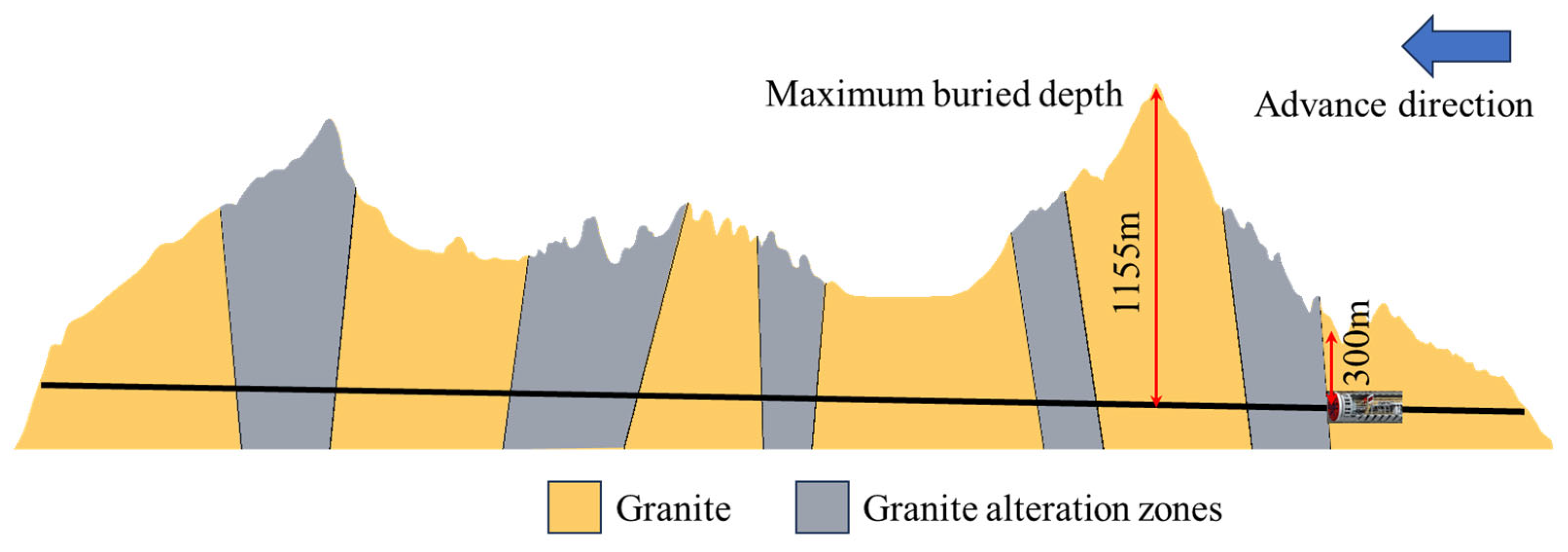
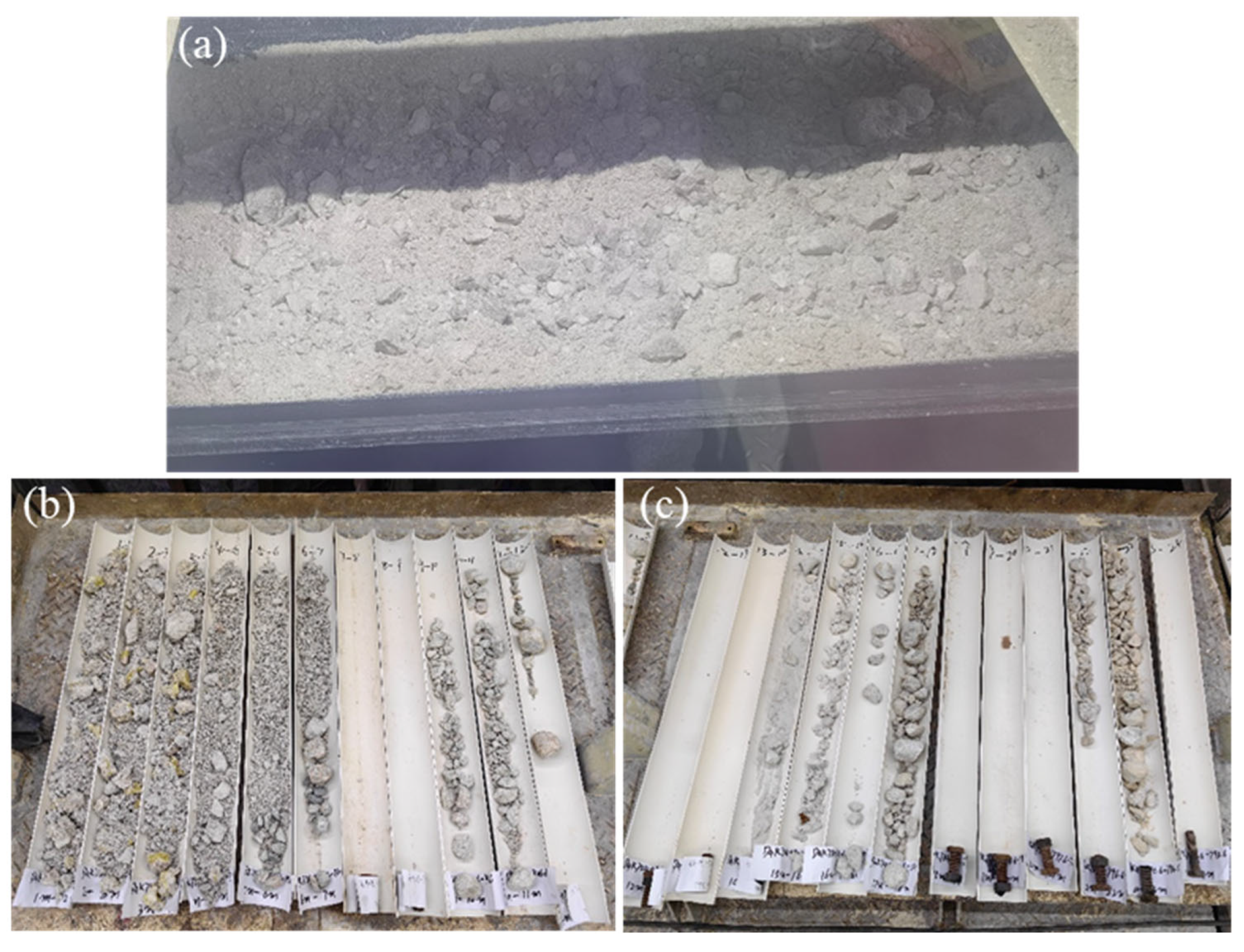
2. Engineering Background

The geological profile of a railway tunnel in southwest China is illustrated in Figure 1. This tunnel spans a total length of 34.538 km and reaches a maximum depth of 1155 m. A gripper TBM was used for excavation, featuring a cutter head diameter of 9.03 m, a shield length of approximately 5 m, an overall machine length of about 230 m, and a total weight of approximately 1900 tons. The rocks surrounding the portal section primarily consist of Yanshan magmatic rocks, with the surface sporadically covered by Quaternary slope residual clay. The tunnel itself passes through a Yanshan magmatic rock formation, which includes five granite alteration zones.
Currently, the excavation has reached the alteration zone near the tunnel entrance, where the depth is approximately 300 m. According to the slag samples and the drilling results of the horizontal drilling core, the surrounding rock of the excavation section is mainly full-to-strong weathering, and some areas are weak weathering. The rock core sample is incomplete rock, showing a large amount of powdery sand and a small amount of block. The rock mass exhibits weak cementation and moderate overall stability, as illustrated in Figure 2. To ensure accurate numerical modeling, compaction tests and triaxial tests (Figure 3) were conducted on the powdery core samples to determine the physical and mechanical properties of the rock in the altered zone.

3. Numerical Simulation

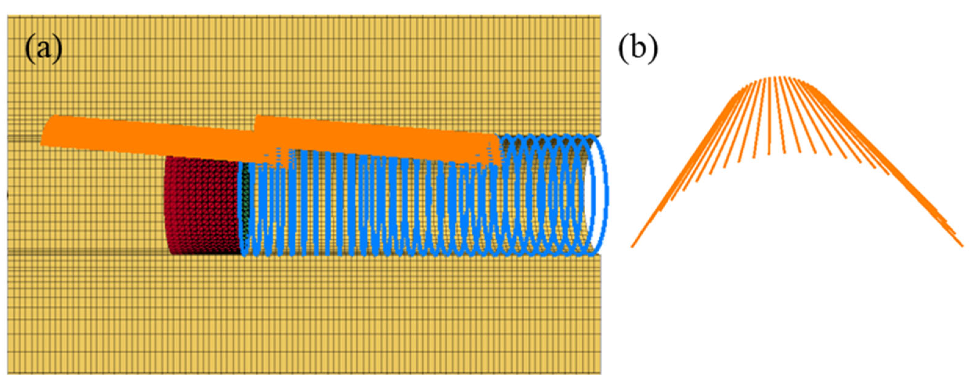
3.1. Numerical Modeling

Numerical simulations were conducted using FLAC3D (version 6.0, Itasca Consulting Group, https://www.itascacg.com/software/flac3d (accessed on 6 February 2025)). This platform was chosen due to its demonstrated efficacy in simulating tunnel excavation processes under complex geological conditions. The mechanical parameters of the granite alteration zone and normal surrounding rock were determined based on site-specific construction data and laboratory tests, as summarized in Table 1. Parameters for normal granite mass were derived from design specifications, while those for the alteration zone were obtained through detailed physical and mechanical testing, ensuring accuracy and reliability.
To replicate real-world excavation conditions, the model dimensions were set to 100 × 100 × 100 m, with a tunnel diameter of 9.03 m. Boundary conditions were defined with fixed constraints on the bottom, left, right, front, and rear faces of the model, and a uniform compressive stress of 6 MPa was applied to the top surface, representing the overburden pressure in the field. The Mohr–Coulomb model was selected to simulate the surrounding rock due to its ability to represent shear failure behavior in weak and weathered rock masses, a common characteristic of alteration zones. The TBM was modeled as a shell, while the steel arch support was represented by a beam.
To account for the over-excavation behavior observed in actual construction, a 5 cm over-excavation gap was introduced, based on the methodology proposed by Huang et al. [31]. This gap was modeled using elastic elements with extremely low-strength parameters and a low deformation modulus, simulating foam-like mechanical behavior to transfer forces between the surrounding rock and the TBM shield. The specific model setup and parameters are illustrated in Figure 4. These careful considerations and site-specific calibrations ensure the reliability of the numerical model in evaluating TBM excavation processes under altered geological conditions.

3.2. Simulation Process

3.2.1. Single-Layer Pipe-Roof Support Simulation Method

Based on the site construction layout, the length of the single-layer pipe-roof support is 25 m, with a longitudinal overlap of 3 m, primarily arranged within 120° of the vault. As shown in Figure 5, considering that the main support effect of the single-layer pipe-roof support relies on the flexural stiffness of the supporting structure, the pile element is used to simulate it. The cross-sectional area and flexural stiffness of the support are modeled according to the Φ76 mm steel pipes.

3.2.2. Double-Layer Large-Pipe-Roof Support Simulation Method

The altered rock is poor in lithology, weak and broken, and has rheological properties under the condition of water, so the advanced support is an effective measure to prevent the TBM becoming jammed. Although the advanced support of the single-layer pipe roof can form a continuous shell in front of the palm face, improve the strength of the stratum, and form a bearing structure in front of the palm face in a certain range, the over-cost protection strength of it cannot meet the requirements of the vault settlement of the TBM in altered rock, so it is necessary to strengthen the advanced support strength. According to the site construction layout, the length of the double-layer large-pipe-roof support is 30 m, and it is connected 3 m vertically. The ring is mainly arranged within 120° of the vault. As shown in Figure 6, considering that the main supporting effect of the double-layer large-pipe-roof support depends on the flexural stiffness of the supporting structure, the pile element is adopted in the simulation to simulate leading it. The cross-sectional area and flexure stiffness of the support are selected according to the Φ108 mm steel pipes.
The two pre-support systems investigated—the single-layer pipe-roof support and double-layer large-pipe-roof support systems—are defined by their geometric, material, and installation parameters, as shown in Table 2.

4. Numerical Experiment Results

4.1. No Advance Support Effect

The deformation characteristics of the surrounding rock as the TBM transitions from normal rock to the alteration zone are detailed in Figure 7. The results indicate that during excavation in normal rock, the unloading process causes significant convergence and deformation of the arch roof, arch bottom, and tunnel face. However, this deformation is primarily elastic, with an overall deformation of less than 1 cm. As the TBM approaches the altered rock mass (at y = 14 m), the excavation induces squeeze deformation at the face. Upon entering the altered rock, the face exhibits significant instability (at y = 15 m), with an elliptical instability area and deformation amplitude reaching 5.5 cm. This instability generates active pressure on the cutter head, increasing thrust during TBM operation. As excavation continues, for example, when the TBM is fully within the altered rock, notable settlement occurs above the shield, creating an active load that can cause the shield to become stuck. In summary, the transition from normal rock to altered rock involves three deformation stages: deformation of the surrounding rock in front of the cutter head, gradual expansion of the deformation zone to the tunnel’s top, and settlement and deformation of the surrounding rock above the shield.
The formation deformation when the TBM reaches y = 21 m and y = 31 m is presented in Figure 8. These two conditions correspond to the TBM shield entering the altered rock and being fully within the altered rock, respectively. In the first condition (y = 21 m), the surrounding rock at the shield tail exhibits noticeable relaxation deformation. However, due to the constraints of the tunnel face and normal surrounding rock, the overall displacement of the surrounding rock around the shield is relatively small. The maximum displacement, occurring 1 m from the shield tail, reaches 15.3 cm, approaching the allowable deformation limit for the TBM. When the shield is fully within the altered rock (y = 31 m), the weakening constraints from the tunnel face and normal rock lead to significant deformation of the surrounding rock. This results in instability deformation in front of and above the shield, with the maximum displacement in these areas exceeding 22 cm.
The settlement and deformation of the soil above the shield at different TBM positions without advance support are shown in Figure 9. At y = 10 m, where the TBM is in normal surrounding rock and far from the alteration zone, the vault settlement is measured to be less than 1 cm. The maximum settlement occurs in the middle of the shield shell. At y = 15 m, as the TBM approaches the alteration zone, the maximum settlement of the arch surrounding rock shifts to the rear of the shield, reaching about 5 cm. This settlement corresponds with the TBM’s over-excavation of 5 cm, indicating that in the normal surrounding rock section, TBM overdigging meets the deformation requirements, avoiding jamming. At y = 21 m and y = 31 m, when the TBM enters the alteration zone, the loose and broken nature of the surrounding rocks, combined with their rheological properties, causes settlement in the arch roof to exceed the 5 cm over-excavation amount. The settlement increases with distance from the cutter head, mainly due to the greater spatial constraint effect near the cutter head. Conversely, the strata behind the shield experience less constraint from the palm face, leading to a linear increase in settlement with distance from the cutter head. Notably, the settlement at the tail of the shield reaches approximately 16.1 cm and 20.8 cm, respectively. This significant settlement causes the surrounding rock to firmly grip the shield shell, making it impossible to avoid jamming even if the shield shrinks by 7.5 cm.
Formation deformation during TBM tunneling also leads to shield extrusion deformation. Figure 10 illustrates shield deformation at different stages. As the shield enters the altered rock, the compressive deformation behind the shield increases significantly. For instance, when the TBM is fully within the altered rock, the maximum shield deformation exceeds 3.5 cm. This trend aligns with the previously observed formation deformation trends.
The deformation of the steel arch support during TBM driving is shown in Figure 11. At y = 21 m, when the steel arch is primarily in normal surrounding rock, its deformation is minimal, with the maximum value recorded as 2.5 mm. However, by y = 31 m, as the TBM reaches the altered rock stratum, the steel arch experiences significant deformation. Due to more complete stress release in the surrounding rock further from the face, the displacement of the steel arch away from the cutter head becomes more pronounced. The maximum deformation of the steel arch reaches 6.7 cm. It is important to note that although the deformation of the steel arch is small, the maximum displacement difference of surrounding rock between adjacent arches is large, indicating that the surrounding rock has obvious instability and collapse.

4.2. Support Effect of Single-Layer Pipe-Roof Support

The formation deformation with the single-layer pipe-roof support at TBM positions y = 21 m and y = 31 m is shown in Figure 12. These positions correspond to the TBM shield entering the altered rock and being fully within the altered rock, respectively. In general, the deformation of the surrounding rock with the single-layer pipe-roof support is similar to that observed without the pre-support. When the shield first enters the altered rock, the primary settlement deformation occurs at the rear of the shield. The constraint from the palm face and normal surrounding rock limits the overall displacement, with a maximum value of 15 cm. As the TBM advances to y = 31 m, the constraint effects from the palm face and normal rock weaken, leading to significant settlement deformation at the top of the shield. The maximum displacement at the shield tail position exceeds 19 cm.
The settlement and deformation of the soil above the shield with the single-layer pipe-roof support at different TBM positions are shown in Figure 13. At y = 10 m, when the TBM is in the intact surrounding rock and far from the alteration zone, the vault settlement is less than 1 cm, with the maximum settlement occurring at the center of the shield shell. At y = 15 m, as the TBM enters the alteration zone, the maximum settlement of the arch surrounding rock shifts to the rear of the shield shell, reaching approximately 3.6 cm. The TBM overdigging is 5 cm, indicating that in the normal surrounding rock section, TBM overdigging meets the deformation requirements, preventing jamming. At y = 21 m and y = 31 m, after entering the alteration zone, the settlement of the arch roof surrounding rock exceeds 5 cm. Due to reduced constraints from the palm face, the formation settlement increases with distance from the cutter head, showing a nearly linear relationship. Notably, the settlement at the tail of the shield shell reaches 10 cm and 19 cm, respectively, suggesting that jamming will still occur despite the pre-support.
As shown in Figure 14, the deformation and stress of the steel pipes are presented. The results indicate that the steel pipes experience flexural deformation due to the formation’s movement during excavation. The maximum deformation reaches 21.8 cm, with a maximum bending moment of 5.62 kN·m and a maximum shear force of 101 kN. The maximum deformation occurs in the middle of steel pipes, while the peak bending moment and shear force are found near the ends. These findings demonstrate that the single-layer pipe-roof support functions similarly to a simply supported beam in altered rock conditions, providing significant support to the weak altered rock above it.
As shown in Figure 15, when the steel arch is supported by the single-layer pipe-roof support, the deformation patterns are similar to those observed without advance support. In normal surrounding rock, the maximum deformation of the steel arch reaches 2.5 mm. However, when the steel arch is in the altered rock zone, significant deformation occurs, with the maximum displacement of 6.3 cm observed at the spinners on both sides. This suggests that the stability of the surrounding rock remains compromised despite the use of the pre-support.

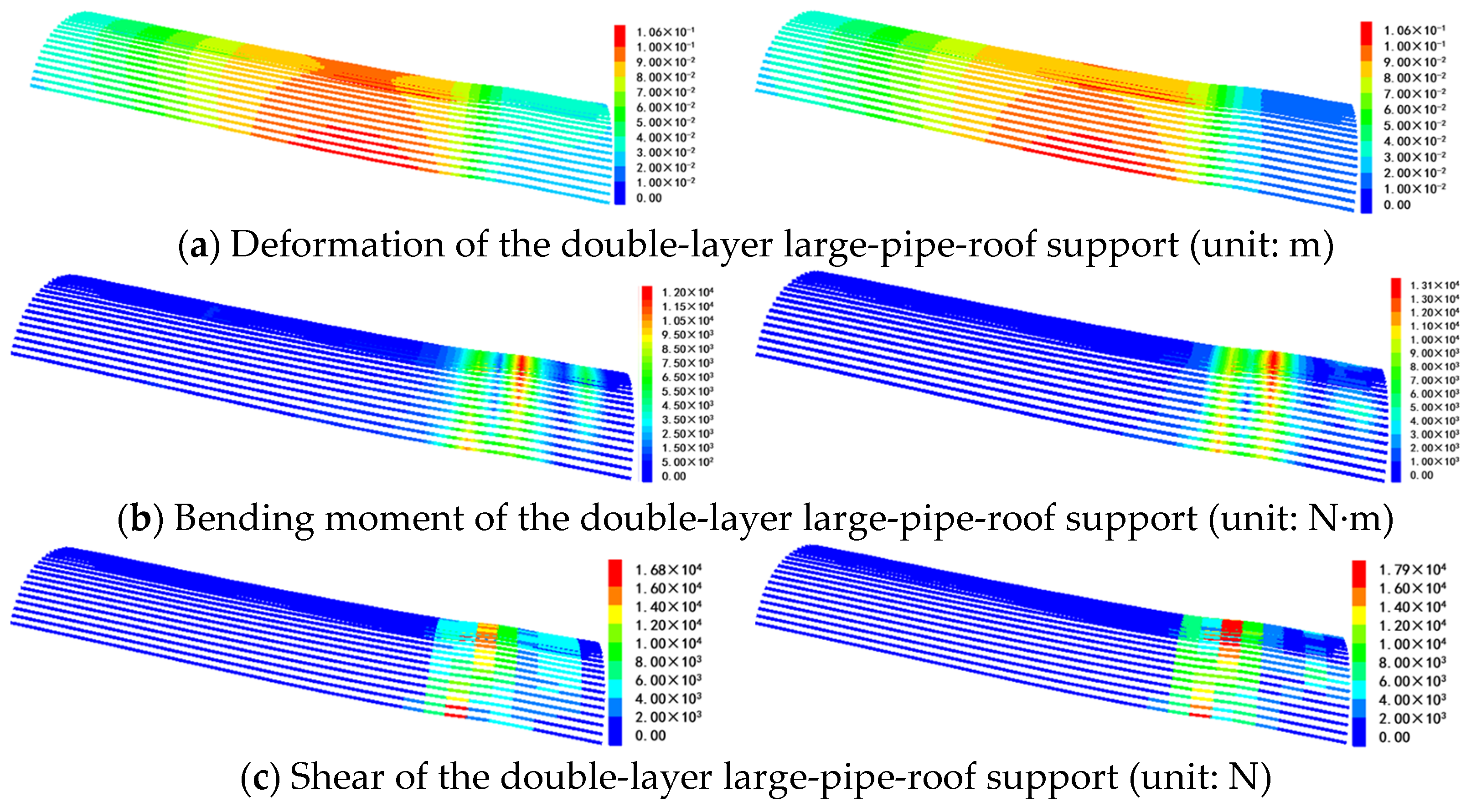
4.3. Supporting Effect of Double-Layer Large-Pipe-Roof Support

As illustrated in Figure 16, the deformation of the surrounding rock under the double-layer large-pipe-roof support is presented. The results indicate that the pre-support significantly influences the development and progression of formation deformation. In the presence of unaltered rock masses, the deformation pattern closely resembles that of unsupported rock, characterized primarily by elastic deformation around the tunnel and the face of the excavation. As excavation progresses, the maximum displacement is concentrated in front of the excavation face, without migrating to the shield’s top. This suggests that the double-layer large-pipe-roof support effectively suppresses vertical displacement development.
Compared to both the unsupported and middle-pipe-shed conditions, the double-layer steel pipes provide significantly better control over surrounding rock deformation (as shown in Figure 17). The results indicate that the maximum deformation occurs in front of the cutter head when using this large pre-support, while the deformation of the surrounding rock above the shield is substantially reduced. This demonstrates that the double-layer steel pipes effectively block and shield soil deformation above the shield, minimizing the impact of TBM tunneling on the tunnel’s surrounding rock, particularly at the top.
Figure 18 shows the settlement of the formation above the shield roof as the cutter head advances under the double-layer large-pipe-roof support. The overall pattern of deformation remains consistent with the previous two conditions: formation settlement increases with distance from the cutter head, and surrounding rock deformation is largely linear in relation to this distance. In normal surrounding rock, the formation deformation mirrors that of the earlier conditions. However, within the altered rock, the displacement is significantly reduced with the double-layer large-pipe-roof support. For example, at Y = 21 m, the maximum displacement is 6.8 cm, and at Y = 31 m, it is 9.7 cm, representing reductions of 45.6% and 53.4%, respectively, compared to the unsupported condition.
It is evident from Figure 19 that the two layers of steel pipes in the double-layer large-pipe-roof support exhibit the same deformation trend. The inner and outer steel pipes exhibit similar deformation patterns, though with differing magnitudes. The maximum displacement values for both the inner and outer steel pipes are concentrated near the midpoints, reaching up to 6.06 cm. The maximum bending moments occur at the near end of the steel pipes, with values of 15 kN·m and 10 kN·m, respectively. Similarly, the maximum shear forces are also located at the near end, measuring 25.4 kN and 12.8 kN. These results suggest that the high flexural stiffness of the pre-support provides substantial support to the weak, altered rock mass above it, effectively mitigating the impact of excavation on the stratum and preventing excessive settlement deformation.
The deformation of the steel arch under the support of the steel pipes mirrors the trends observed in the previous simulations. For the steel arch situated in normal surrounding rock, the maximum deformation is 2.7 mm. However, significant deformation occurs in the steel arch located within the altered rock. Notably, the maximum displacement in the altered rock section appears at the arch waists on both sides, reaching 7.7 cm. This pronounced deformation may be attributed to the load transfer effects of the pre-support.

5. Discussion

To further assess the effectiveness of different support systems on surrounding rock during TBM excavation, we analyzed the development of formation settlement and deformation across three scenarios: unsupported, single-layer pipe-roof support, and double-layer large-pipe-roof support. As can be seen from Figure 20, the settlement deformation during TBM excavation can be divided into three stages. Stage I involves the displacement as the cutter head approaches the monitoring section, where displacement begins when the cutter head is 11 m from the section, with settlement becoming more pronounced as it nears. Stage II refers to the displacement as the shield passes through the monitoring section, while Stage III involves displacement after the shield has passed. The deformation at different stages under the three working conditions is summarized in Table 3. During construction, displacement in Stage II is critical, as it can lead to contact between the formation and the shield, potentially causing the shield to become stuck if the displacement exceeds the allowable expansion. The results show that the overall displacement and stage-specific displacement proportions did not change significantly with the use of the middle-pipe-shed support. However, after the adoption of the double-layer large pipe shed, the maximum displacement of the monitored section was reduced by nearly 50%, and Stage II displacement was also significantly decreased. This demonstrates that the double-layer large pipe shed effectively controls surrounding rock deformation, preventing TBM jamming in such formations.
The enhanced performance of the double-layer support system underscores its potential benefits in ensuring TBM operability, particularly in weak or complex geological conditions. The dual-layer configuration distributes loads more efficiently and mitigates local stress concentrations, thereby reducing the likelihood of excessive deformation and subsequent TBM entrapment. However, while double-layer supports exhibit significant deformation control advantages, their practical implementation presents certain challenges. The installation process is notably time consuming, particularly in TBM-driven tunnels where the confined working space—exacerbated by the presence of excavation equipment—can severely limit drilling efficiency. This stands in contrast to conventional drill-and-blast methods, where there is more flexibility and accessibility for pre-support installation. During advanced support with the existing TBM equipment, the onboard drilling machine is not capable of handling the drilling work, necessitating the use of additional equipment for drilling and grouting. For the medium pipe shed, each steel pipe is 25 m long, and a single borehole takes approximately 4–5 h. In contrast, for the large pipe shed, each steel pipe is 30 m long, and a single borehole requires over 10 h. With a spacing of 0.5 m between the steel pipes and based on the installation of a 120° range at the tunnel arch of a 9 m diameter tunnel in this project, the drilling time required for the medium pipe shed is about 3 h per meter of tunnel length, whereas for the double-layer large pipe shed, it is approximately 16 h per meter.
In addition to the time-intensive nature of double-layer support installation, the increased logistical complexity and associated costs must be carefully weighed against the operational benefits. For instance, in highly complex geological settings—such as water-rich formations or extensively fractured zones—these supports may need to be integrated with other reinforcement strategies, including drainage systems and grouting reinforcement. Future studies could benefit from a multi-criteria analysis that includes cost–benefit metrics, construction timelines, and risk assessments under varying geological conditions.
It is also important to acknowledge the limitations of this study. The investigation was conducted under conditions characterized by relatively shallow overburden depths, and as such, the conclusions drawn may not be directly applicable to deeper tunnel scenarios where higher in situ stresses prevail. In deeper tunnels, the interaction between the support systems and the surrounding rock mass may differ significantly due to elevated stress conditions, potentially leading to different deformation characteristics.
Furthermore, the study focuses on only two pre-support measures. In real-world tunnel construction, it is common to employ a combination of support techniques—such as drainage, grouting reinforcement, and other stabilization measures—to achieve the desired safety and operational efficiency. While steel pipe supports have proven effective, their use is accompanied by challenges, including prolonged construction time, higher costs, and the risk of TBM jamming.
Looking forward, future research should aim to explore the applicability and optimization of these support systems under a broader range of geological and operational conditions. A promising avenue for further investigation is the development of quantified and graded mitigation strategies that integrate multiple support methods. Such strategies should be tailored based on detailed geological investigations and risk assessments, ensuring that the chosen support configuration is both effective in controlling deformation and operationally efficient.

6. Conclusions

This section mainly analyzes the deformation of surrounding rock under different advance supporting conditions, and the main conclusions are as follows:
(1)
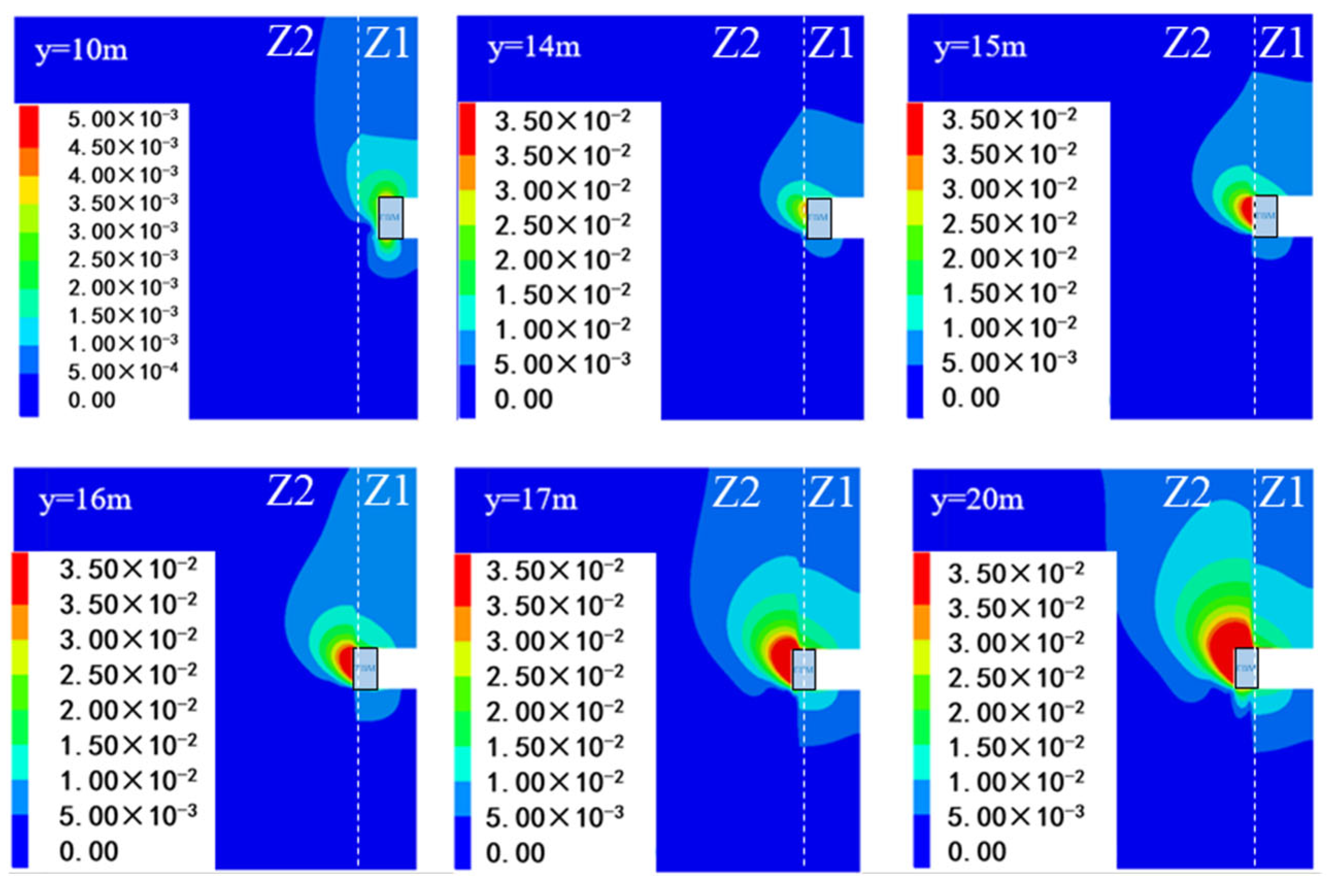
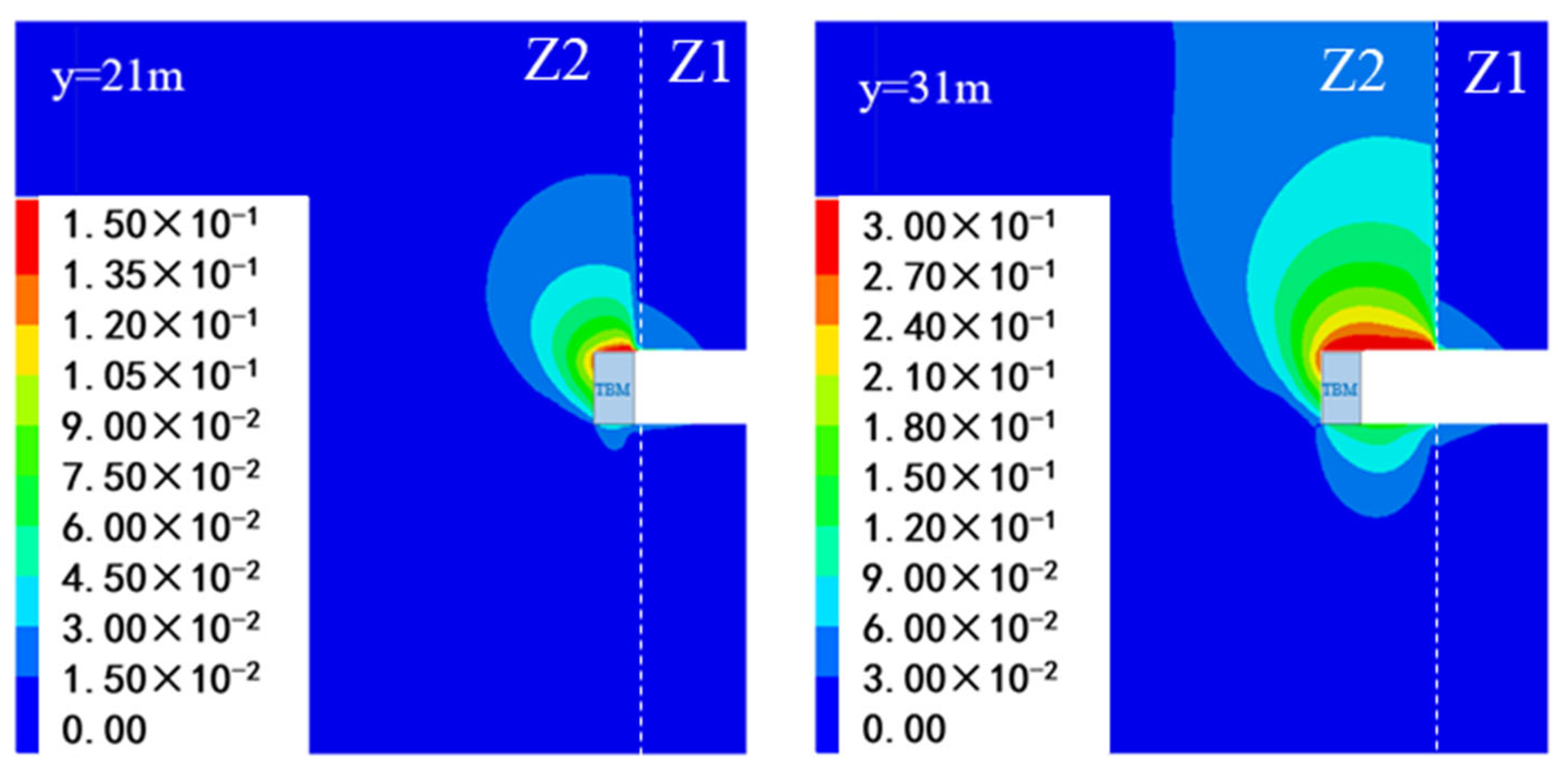
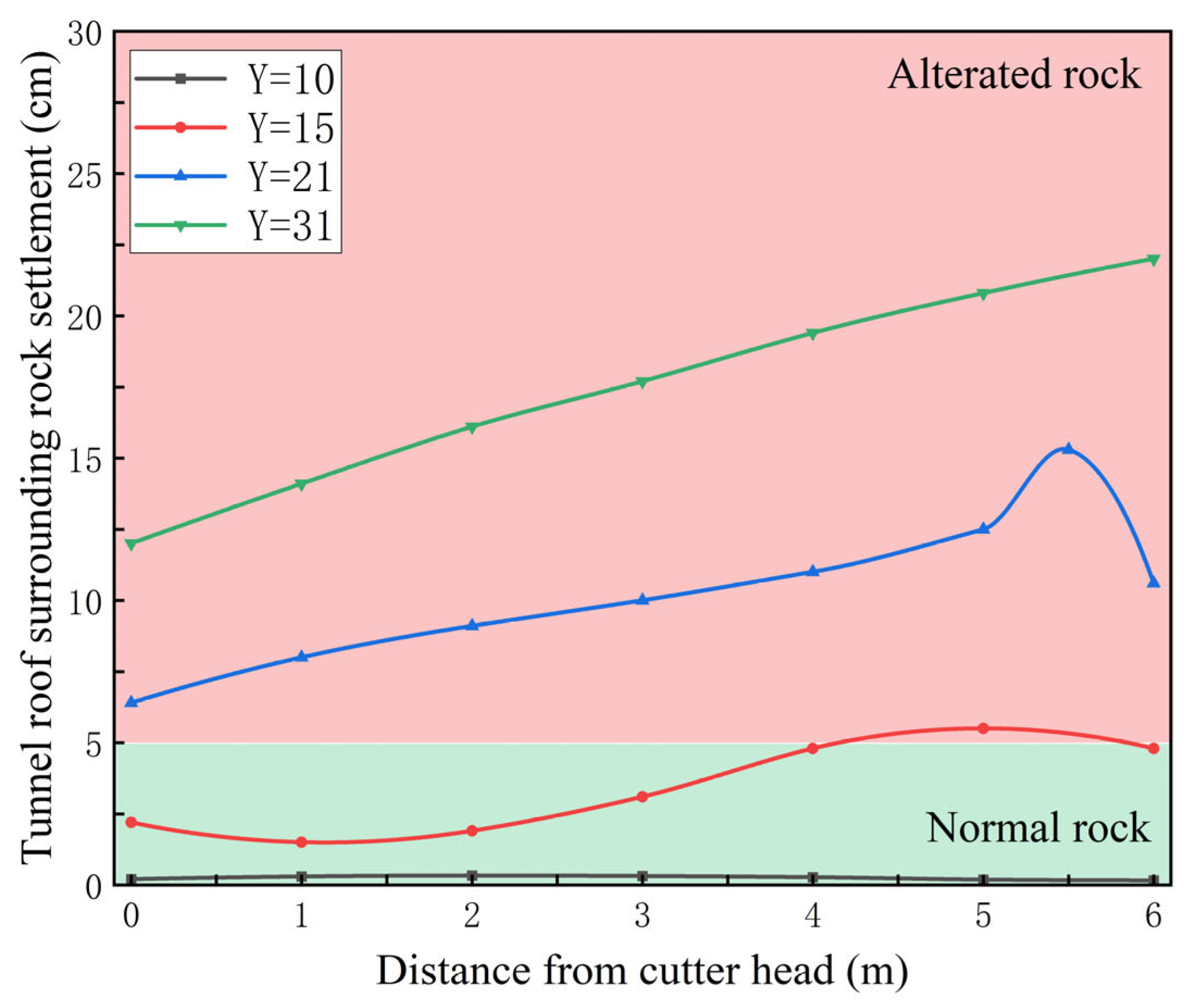
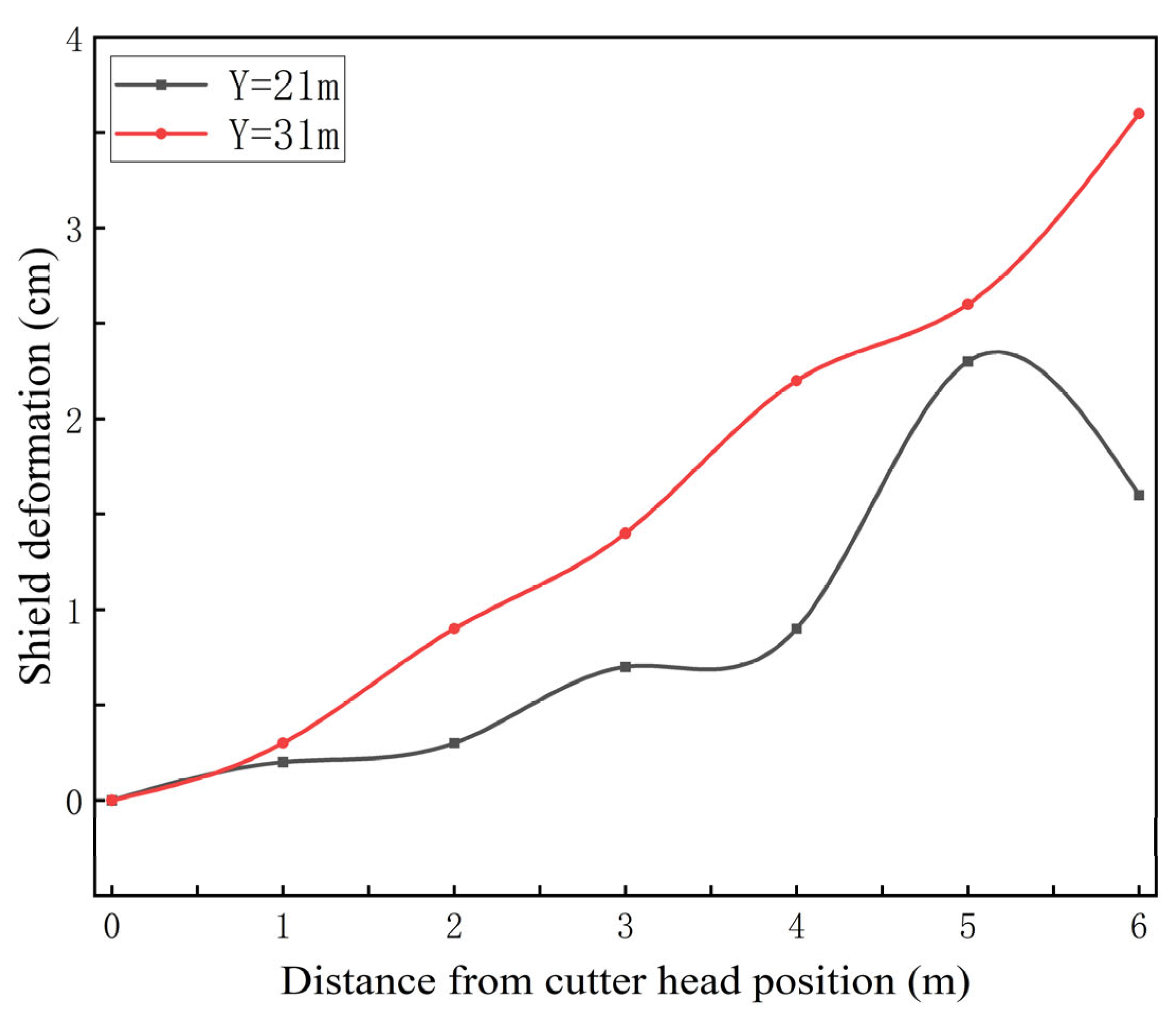
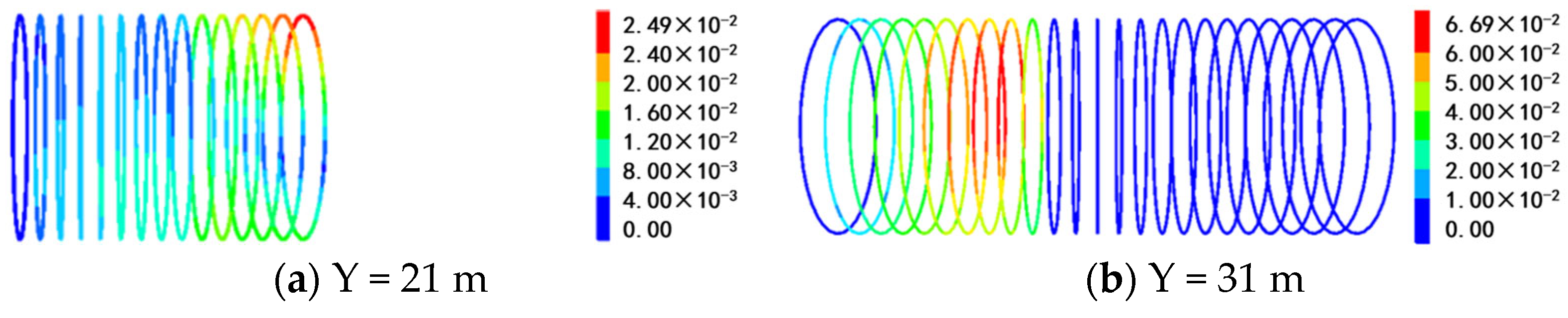
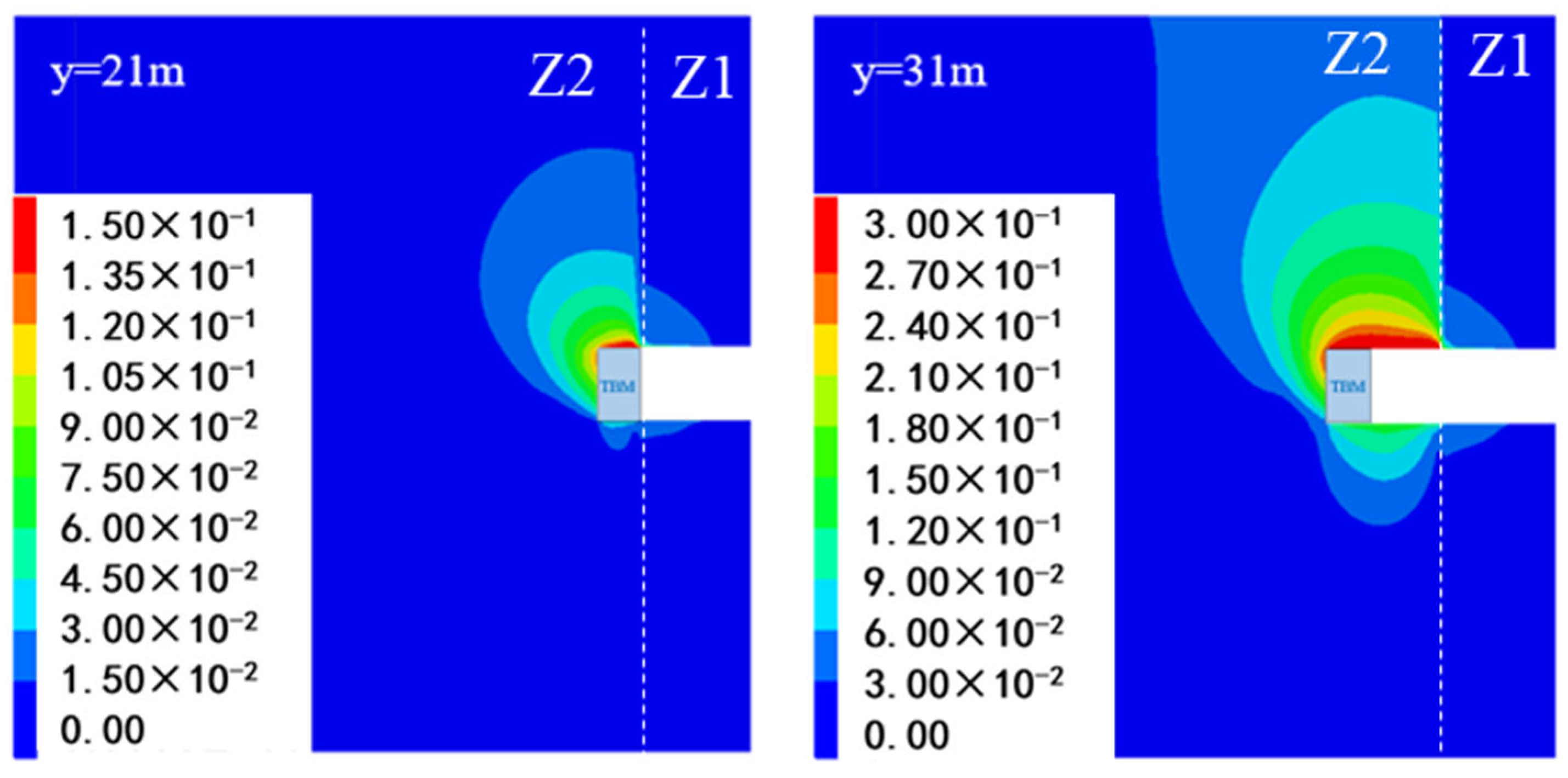
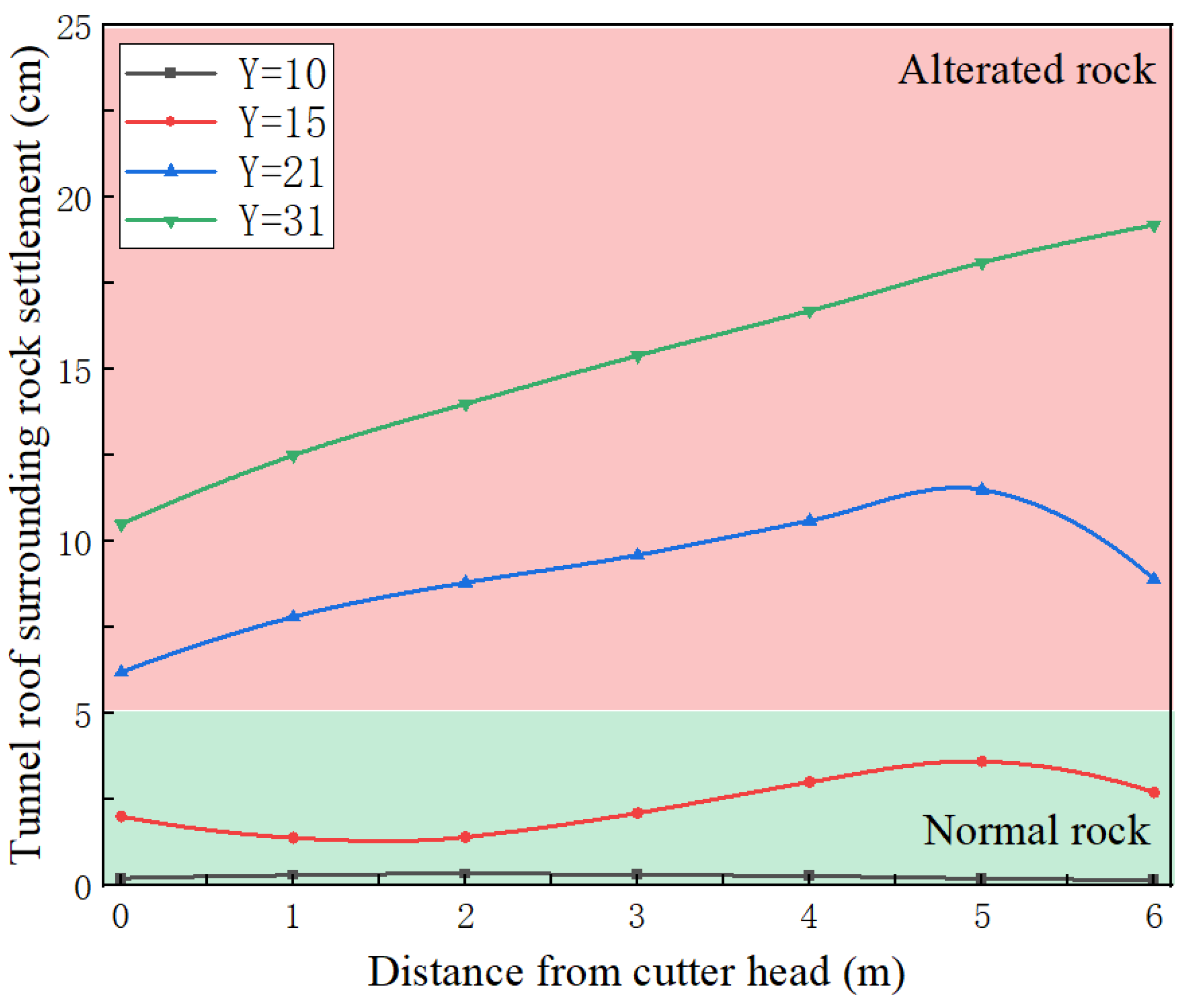
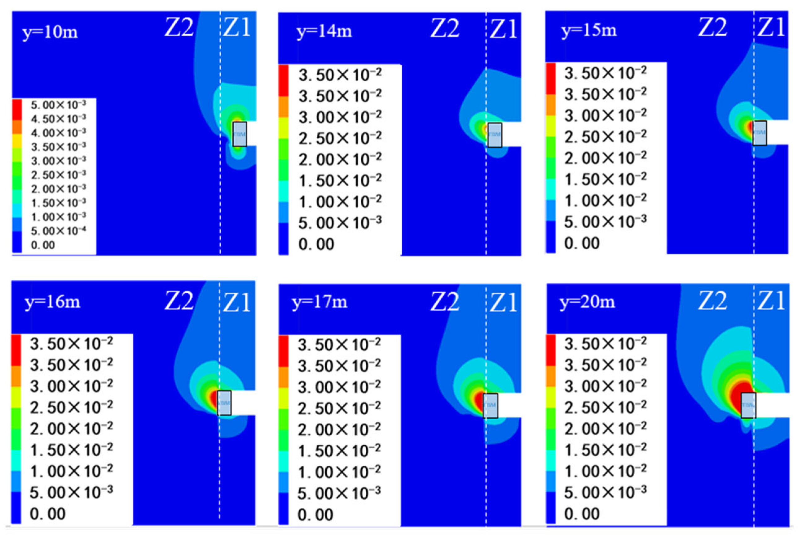
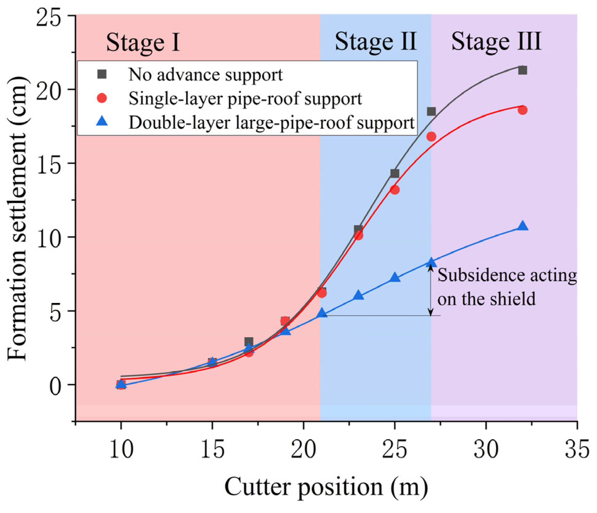
When the TBM transitions from normal surrounding rock to altered rock, the excavation’s stability decreases due to the poorer physical and mechanical properties of the altered rock. The deformation of the surrounding rock around the tunnel occurs in three stages: deformation in front of the cutter head, gradual expansion of the deformation zone to the tunnel crown, and settlement and deformation above the TBM shield.
(2)
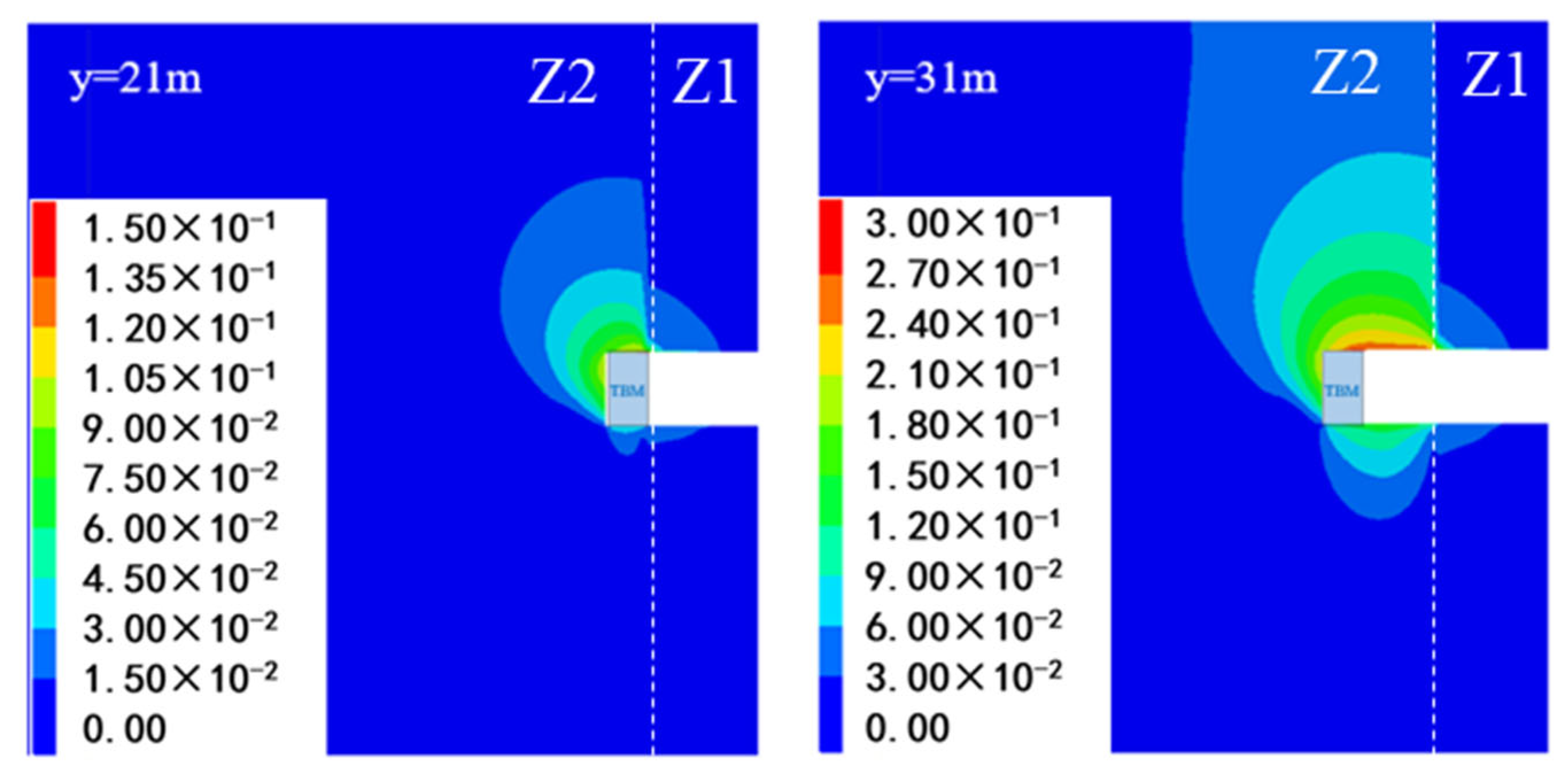
Without advance support, TBM driving in altered rock can cause a maximum displacement of 20.8 cm, with shield deformation exceeding 3.5 cm. This indicates that in such conditions, the surrounding rock may completely lock the TBM shield, leading to jamming.
(3)
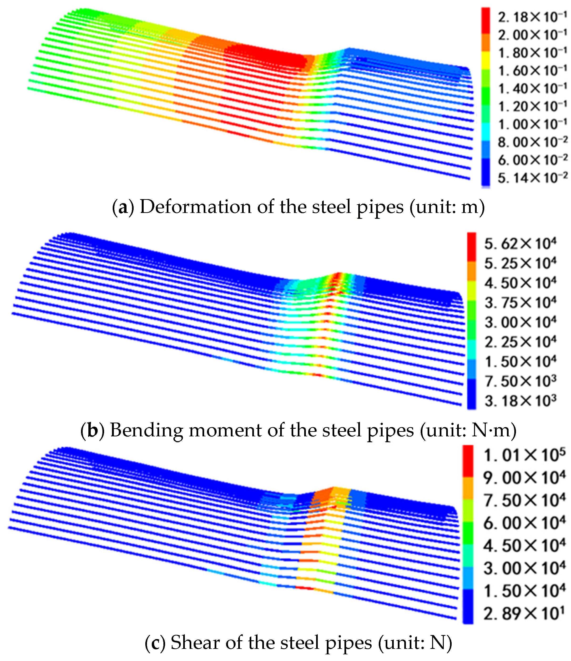
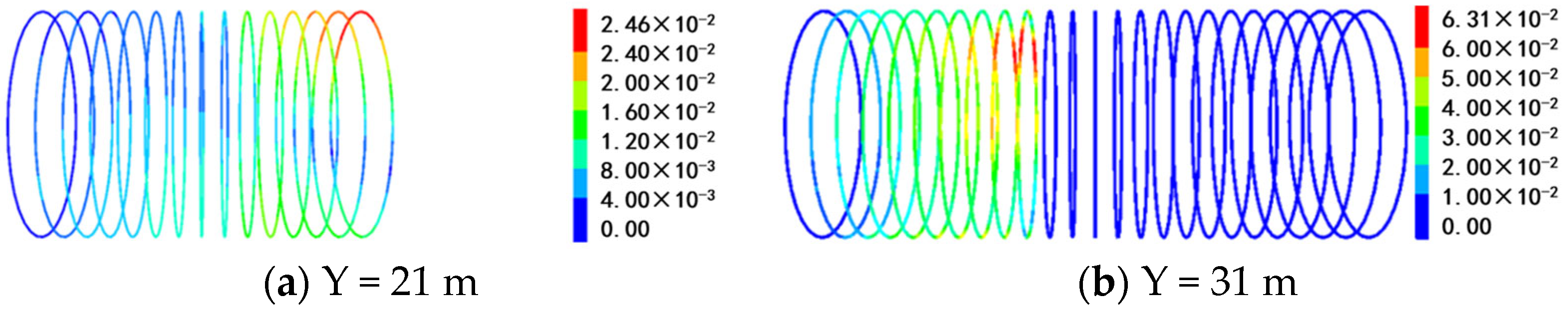
Although a single-layer steel pipe offers some support, its limited flexural rigidity means that TBM tunneling in altered rock still results in significant displacement, up to 19.2 cm, with steel arch deformation reaching 6.3 cm. This suggests a high risk of large deformation and potential jamming in such conditions.
(4)
In contrast, a double-layer large-pipe-roof support, with its superior bending stiffness, effectively controls settlement and deformation, reducing maximum roof displacement to 9.7 cm—a 53.4% reduction compared to tunneling without advance support.
(5)
Overall, the single-layer pipe-roof support has little impact on the displacement evolution or maximum settlement, while double-layer large pipe sheds significantly reduce settlement and shield displacement. Therefore, the double-layer large-pipe-roof support provides better support in these formations and mitigates the risk of TBM jamming.

Author Contributions

J.W.: writing (review and editing), data curation. Z.Y. (Zhigang Yao): software, data curation. J.H.: writing (review and editing), visualization. L.F.: methodology. Y.F.: conceptualization, supervision. K.F.: data curation, supervision. Z.Y. (Zhiyong Yang): data curation, supervision. J.Y.: supervision, resources. All authors have read and agreed to the published version of the manuscript.

Funding

This work was financially supported by the National Science Fund for Distinguished Young Scholars (Grant No. 52425807), the National Natural Science Foundation of China (Grant No. 52408441), the Sichuan Youth Science and Technology Innovation research team project (Grant No. 2024NSFTD0013), the Sichuan ‘Top Youth’ Special Program for Outstanding Young Science and Technology Talent (Grant No. DQ202403), and the Yunnan Province science and technology plan project (Grant No. 202303AA08005).

Data Availability Statement

The datasets used and/or analyzed during the current study are available from the corresponding author upon reasonable request.

Conflicts of Interest

Author Lei Fan was employed by the company China Railway Eryuan Engineering Group Co., Ltd. Authors Kejun Fang, Zhiyong Yang and Jiabin Yan were employed by the company Yungui Railway Yunnan Co., Ltd. The remaining authors declare that the research was conducted in the absence of any commercial or financial relationships that could be construed as a potential conflict of interest.

References

  1. Zheng, Y.L.; Zhang, Q.B.; Zhao, J. Challenges and Opportunities of Using Tunnel Boring Machines in Mining. Tunn. Undergr. Space Technol. 2016, 57, 287–299. [Google Scholar] [CrossRef]
  2. Fan, S.; Song, Z.; Zhang, Y.; Liu, N. Case Study of the Effect of Rainfall Infiltration on a Tunnel Underlying the Roadbed Slope with Weak Inter-Layer. KSCE J. Civ. Eng. 2020, 24, 1607–1619. [Google Scholar] [CrossRef]
  3. Fan, S.; Song, Z.; Xu, T.; Wang, K.; Zhang, Y. Tunnel Deformation and Stress Response under the Bilateral Foundation Pit Construction: A Case Study. Arch. Civ. Mech. Eng. 2021, 21, 109. [Google Scholar] [CrossRef]
  4. Karahan, S.; Yilmaz, O.; Karsli, Y.; Gokceoglu, C. A TBM Application in Shallow and Weak Ground Conditions (Ankara-Izmir High-Speed Railway Construction Project, Türkiye). In Proceedings of the 57th U.S. Rock Mechanics/Geomechanics Symposium, Atlanta, GA, USA, 25–28 June 2023. [Google Scholar] [CrossRef]
  5. Strappler, G.; Vigl, A.; Scheutz, R. Two-layer Lining for ÖBB Railway Tunnel Projects with TBM/Ein-und Zweischalige Auskleidung Bei Tunnelbauprojekten Der ÖBB Mit Kontinuierlichem Vortrieb. Geomech. Tunn. 2012, 5, 72–88. [Google Scholar] [CrossRef]
  6. Lu, Z.; Wang, X.; Zhou, G.; Feng, L.; Jiang, Y. Investigation on Vibration Influence Law of Double-Shield TBM Tunnel Construction. Appl. Sci. 2022, 12, 7727. [Google Scholar] [CrossRef]
  7. Scolari, F. Open-Face Borers in Italian Alps. In World Tunnelling and Subsurface Excavation; The Mining Journal Ltd.: London, UK, 1995; Volume 8, pp. 361, 363–366. [Google Scholar]
  8. Tang, B.; Chen, X.; Sun, C.; Cheng, S.; Tang, Y.; Wang, C. A Case Study on Control Technology of Surrounding Rocks of TBM Assembly Chamber in Underground Coal Mines. Arab. J. Geosci. 2022, 15, 450. [Google Scholar] [CrossRef]
  9. Marchionni, M.; Selleri, A.; Stahl, F.; Messina, L. Intensive Application of the TBM Data Management System for the Work Supervisor of the Largest Worldwide TBM-EPB Project. In Proceedings of the World Tunnel Congress WTC 2013, Geneva, Switzerland, 31 May–5 June 2013; pp. 1312–1319. [Google Scholar]
  10. Fang, Y.; Cui, J.; Wanatowski, D.; Nikitas, N.; Yuan, R.; He, Y. Subsurface Settlements of Shield Tunneling Predicted by 2D and 3D Constitutive Models Considering Non-Coaxiality and Soil Anisotropy: A Case Study. Can. Geotech. J. 2022, 59, 424–440. [Google Scholar] [CrossRef]
  11. Dong, L.; Song, D.; Liu, G. Seismic Wave Propagation Characteristics and Their Effects on the Dynamic Response of Layered Rock Sites. Appl. Sci. 2022, 12, 758. [Google Scholar] [CrossRef]
  12. Tian, X.; Song, Z.; Zhang, Y. Monitoring and Reinforcement of Landslide Induced by Tunnel Excavation: A Case Study from Xiamaixi Tunnel. Tunn. Undergr. Space Technol. 2021, 110, 103796. [Google Scholar] [CrossRef]
  13. Tian, X.; Song, Z.; Wang, H.; Zhang, Y.; Wang, J. Evolution Characteristics of the Surrounding Rock Pressure and Construction Techniques: A Case Study from Taoshuping Tunnel. Tunn. Undergr. Space Technol. 2022, 125, 104522. [Google Scholar] [CrossRef]
  14. Zhang, Y.; Wang, J.; Liu, F.; Xia, H. Mechanism and Sensitivity Analysis of Collapse in Large Section Mountain Neighborhood Tunnels. Front. Earth Sci. 2022, 10, 904655. [Google Scholar] [CrossRef]
  15. Zhao, M.; Cheng, Y.; Song, Z.; Wang, T.; Zhang, Y.; Gong, Y.; Song, Y. Stability Analysis of TBM Tunnel Undercrossing Existing High-Speed Railway Tunnel: A Case Study from Yangtaishan Tunnel of Shenzhen Metro Line 6. Adv. Civ. Eng. 2021, 2021, 6674862. [Google Scholar] [CrossRef]
  16. Xiaoli, L.I.U.; Huan, S.U.N.; Qinxi, D.; Xiong, Y.; Kumar, N.; Yan, S.U.; Jianjun, Z. Extremely Hard Rock Mass Excavation Using Rock Breakdown Methods to Assist TBM in a Deep, Long Diversion Tunnel in the Qinling Mountains. J. Tsinghua Univ. (Sci. Technol.) 2022, 62, 1292–1301. [Google Scholar]
  17. Bayati, M.; Hamidi, J.K. A Case Study on TBM Tunnelling in Fault Zones and Lessons Learned from Ground Improvement. Tunn. Undergr. Space Technol. 2017, 63, 162–170. [Google Scholar] [CrossRef]
  18. Acun, S.; Bilgin, N.; Erboylu, U. Contribution on the Understanding of EPB-TBM Drives in Complex Geologic Structures. Tunn. Undergr. Space Technol. 2021, 107, 103646. [Google Scholar] [CrossRef]
  19. Vibert, C.; Gupta, S.C.; Felix, Y.; Binquet, J.; Robert, F. Dul Hasti Hydroelectric Project (India): Experience Gained from Back Analysis of the Excavation of the Head Race Tunnel. In Proceedings of the Geoline 2005 International Symposium, Lyon, France, 23–25 May 2005; p. 154. [Google Scholar]
  20. Shang, Y.J.; Yang, Z.F.; Zeng, Q.L.; Sun, Y.C.; Shi, Y.Y.; Yuan, G.X. Retrospective Analysis of TBM Accidents from Its Poor Flexibility to Complicated Geological Conditions. Chin. J. Rock Mech. Eng. 2007, 26, 2404–2411. [Google Scholar]
  21. Hao, J.; Yin, Q.; Yong, L.I.; Liu, J.-F. Measures and Adaptability of Constructing Tunnel Crossing Compacted Granite under High Geostress. J. Chang. River Sci. Res. Inst. 2022, 39, 141. [Google Scholar] [CrossRef]
  22. Zhang, Y.; Li, J.; Ren, S.; Wu, R.; Bi, J. Development Characteristics of Clayey Altered Rocks in the Sichuan-Tibet Traffic Corridor and Their Promotion to Large-Scale Landslides. Earth Sci. 2022, 47, 1945–1956. [Google Scholar]
  23. Li, J.; Zhang, Y.; Ren, S.; Bi, J. Catastrophic Mechanical Behavior of Clay-Altered Rock in the Baige Landslide Upstream of the Jinsha River. Adv. Eng. Sci. 2024, 56, 72–82. [Google Scholar] [CrossRef]
  24. Zhang, J.; Wu, T.; Yan, X.; Dong, J.; Shi, S. Study on the Influence of Granite Alteration Degree on Tunnel Stability. J. North China Univ. Water Resour. Electr. Power (Nat. Sci. Ed.). Available online: https://link.cnki.net/urlid/41.1432.TV.20240325.1752.004 (accessed on 2 February 2025).
  25. Hoek, E. Big Tunnels in Bad Rock. J. Geotech. Geoenviron. Eng. 2001, 127, 726–740. [Google Scholar] [CrossRef]
  26. Ma, B.; Wu, S.; Chen, Q.; Liang, E.; Li, X. The Influence of Existing Piles on Station Settlement during the Construction of a Tunnel Undercrossing under Existing Stations. Sci. Rep. 2024, 14, 14024. [Google Scholar] [CrossRef] [PubMed]
  27. Rong, Y.; Du, W.; Sun, Y.; Xiong, F.; Liu, L.; Yu, S.; Jie, G. Study on Stress Deformation of Pipe Shed in Shallow Buried Tunnel Considering Micro-Arch Effect. Adv. Civ. Eng. 2024, 2024, 6651993. [Google Scholar] [CrossRef]
  28. Ou, X.; Ouyang, L.; Zhang, X.; Zhang, Y.; Tian, J. Floor Heave Mechanism and Prevention Countermeasures for High-Pressure Water-Rich Karst Tunnels-All Databases. Available online: https://webofscience.clarivate.cn/wos/alldb/full-record/CSCD:7621011 (accessed on 15 January 2025).
  29. Ding, W.; Huang, X.; Dai, Z.; Wang, C.; Wang, Z.; Yu, W. Analysis of the Collapse Mechanism and Stabilization Optimization of the Composite Stratum at the Boundary between Prereinforced and Unreinforced Areas near a Shield Launching Area. Int. J. Geomech. 2023, 23, 5023002. [Google Scholar] [CrossRef]
  30. Fang, Y.; Yao, Z.; Xu, W.; Tian, Q.; He, C.; Liu, S. The Performance of TBM Disc Cutter in Soft Strata: A Numerical Simulation Using the Three-Dimensional RBD-DEM Coupled Method. Eng. Fail. Anal. 2021, 119, 104996. [Google Scholar] [CrossRef]
  31. Huang, F.; Zhu, H.; Jiang, S.; Liang, B. Excavation-Damaged Zone around Tunnel Surface under Different Release Ratios of Displacement. Int. J. Geomech. 2017, 17, 04016094. [Google Scholar] [CrossRef]
  32. Tian, M.; Gao, X.; Zhang, A.; Han, L.; Xiao, H. Study on the Deformation Failure Mechanism and Coupling Support Technology of Soft Rock Roadways in Strong Wind Oxidation Zones. Eng. Fail. Anal. 2024, 156, 107840. [Google Scholar] [CrossRef]
  33. Xu, X.; Wu, Z.; Liu, Q. An Improved Numerical Manifold Method for Investigating the Mechanism of Tunnel Supports to Prevent Large Squeezing Deformation Hazards in Deep Tunnels. Comput. Geotech. 2022, 151, 104941. [Google Scholar] [CrossRef]
  34. He, B.-G.; Lin, B.; Li, H.-P.; Zhu, S.-Q. Suggested Method of Utilizing Soil Arching for Optimizing the Design of Strutted Excavations. Tunn. Undergr. Space Technol. 2024, 143, 105450. [Google Scholar] [CrossRef]
  35. Qin, Y.; Shang, C.; Li, X.; Lai, J.; Shi, X.; Liu, T. Failure Mechanism and Countermeasures of Rainfall-Induced Collapsed Shallow Loess Tunnels under Bad Terrain: A Case Study. Eng. Fail. Anal. 2023, 152, 107477. [Google Scholar] [CrossRef]
  36. Forsat, M.; Taghipoor, M.; Palassi, M. 3D FEM Model on the Parameters’ Influence of EPB-TBM on Settlements of Single and Twin Metro Tunnels during Construction. Int. J. Pavement Res. Technol. 2022, 15, 525–538. [Google Scholar] [CrossRef]
  37. Fang, X.; Yang, J.; Zhang, X.; Zhang, C.; Wang, S.; Xie, Y. Numerical Modeling of Open TBM Tunneling in Stratified Rock Masses Using a Coupled FDM-DEM Method. Comput. Geotech. 2023, 156, 105251. [Google Scholar] [CrossRef]
  38. Jiang, B.; Wang, L.; Gu, S.; Zhang, X.; Li, W. Study on Rockburst Mechanism of TBM Excavation for Deep Tunnel Based on Energy Principle. J. Min. Saf. Eng. 2017, 34, 1103. [Google Scholar]
  39. Mikaeil, R.; Bakhshinezhad, H.; Haghshenas, S.S.; Ataei, M. Stability Analysis of Tunnel Support Systems Using Numerical and Intelligent Simulations (Case Study: Kouhin Tunnel of Qazvin-Rasht Railway). Rud.-Geološko-Naft. Zb. 2019, 34, 11. [Google Scholar] [CrossRef]
Figure 1. Schematic diagram of the tunnel’s geological profile.
Buildings 15 00509 g001
Figure 2. Tunnel construction site advanced core drawing: (a) belt slag condition, (b) advance core sampling 0–12 m, (c) advance core sampling 12–24 m.
Buildings 15 00509 g002
Figure 3. Physical and mechanical test process of powder core: (a) compaction test, (b) triaxial test.
Buildings 15 00509 g003
Figure 4. Flac3D numerical calculation model.
Buildings 15 00509 g004
Figure 5. Simulation of single-layer pipe-roof support: (a) side view, (b) front view.
Buildings 15 00509 g005
Figure 6. Double-layer large-pipe-roof support simulation: (a) side view, (b) front view.
Buildings 15 00509 g006
Figure 7. Characteristics of TBM construction disturbance in the absence of advance support (unit: m). The y-axis represents the excavation distance (x m). Z1 indicates the normal granite region, while Z2 represents the granite alteration zones.
Buildings 15 00509 g007
Figure 8. Formation deformation at different stages without advance support (unit: m). The y-axis represents the excavation distance (x m). Z1 indicates the normal granite region, while Z2 represents the granite alteration zones.
Buildings 15 00509 g008
Figure 9. Surrounding rock settlement at different positions of the shield roof without advance support.
Buildings 15 00509 g009
Figure 10. Deformation of shield at different stages without advance support.
Buildings 15 00509 g010
Figure 11. Deformation of steel arch at different stages without advance support (unit: m).
Buildings 15 00509 g011
Figure 12. Formation deformation at different stages under the single-layer pipe-roof support (unit: m). The y-axis represents the excavation distance (x m). Z1 indicates the normal granite region, while Z2 represents the granite alteration zones.
Buildings 15 00509 g012
Figure 13. Surrounding rock settlement at different positions of shield roof under single-layer pipe-roof support.
Buildings 15 00509 g013
Figure 14. Deformation and bending moment of the steel pipes.
Buildings 15 00509 g014
Figure 15. Deformation of steel arch in different stages under single-layer pipe-roof support (unit: m).
Buildings 15 00509 g015
Figure 16. Disturbance characteristics of TBM construction under the double-layer large-pipe-roof support (unit: m). The y-axis represents the excavation distance (x m). Z1 indicates the normal granite region, while Z2 represents the granite alteration zones.
Buildings 15 00509 g016
Figure 17. Characteristics of TBM construction disturbance under the double-layer large-pipe-roof support (unit: m). The y-axis represents the excavation distance (x m). Z1 indicates the normal granite region, while Z2 represents the granite alteration zones.
Buildings 15 00509 g017
Figure 18. Surrounding rock settlement at different positions of shield roof under double-layer large-pipe-roof support.
Buildings 15 00509 g018
Figure 19. Deformation and stress of the double-layer large-pipe-roof support (left side is the inner steel pipes, right side is the outer steel pipes).
Buildings 15 00509 g019
Figure 20. Formation deformation and evolution during tunneling (y = 21 m).
Buildings 15 00509 g020
Table 1. Calculation of physical parameters.
CategoryVolume-Weight (kN/m3)Elasticity Modulus (MPa)Poisson’s RatioCohesion (kPa)Internal Friction Angle (°)
Granite alteration zone18.03816.490.3939.722.4
Intact granite27.015,0000.28100045
Table 2. Simulation parameters of advance support measures.
Pre-Support SystemLength/mVertical Spacing of Steel Pipe/mSimulation Unitρ/(kg/m3)E/GPaνI/m4Cross-Sectional Area/ m2
Single-layer pipe-roof support25-Pile78502000.3111.95 × 10−84.53 × 10⁻³
Double-layer large-pipe-roof support300.4250.9 × 10−89.16 × 10⁻³
Note: ρ, E, ν, and I represent density, elastic modulus, Poisson’s ratio, and moment of inertia, respectively.
Table 3. The percentage of deformation in the total deformation of each of the three working conditions.
CaseDeformation as a Percentage of Total Deformation
Stage IStage IIStage III
No advance support29.6%57.3%13.1%
Single-layer pipe-roof support33.3%57%9.7%
Double-layer large-pipe-roof support44.9%31.8%23.3%
Disclaimer/Publisher’s Note: The statements, opinions and data contained in all publications are solely those of the individual author(s) and contributor(s) and not of MDPI and/or the editor(s). MDPI and/or the editor(s) disclaim responsibility for any injury to people or property resulting from any ideas, methods, instructions or products referred to in the content.

