Abstract
The aim of this study was to determine the load-bearing capacity of Klein’s floors under fire conditions using analytical and numerical analyses. Analytical and numerical simulations were performed considering different structural variants of Klein’s floors. A numerical FEM model was developed in Abaqus to create temperature profiles of the beam-to-beam slabs and steel beams, and the fire load-bearing capacity of Klein’s celling after being exposed to fire for 30, 60, and 120 min was calculated analytically. The analytical method of assessing the fire load-bearing capacity of Klein’s floors uses temperature profiles, which allow for calculations to verify fire resistance in the time domain of different structural variants of Klein’s floors. (1) Introduction: The structural solutions of Klein’s floors are widely known, but no studies in the literature have addressed the mechanics of these elements under fire conditions. Both the beam-to-beam slab and steel beams are sensitive to high temperatures. Providing the required level of fire safety in buildings with Klein’s ceilings is a complex issue that requires detailed analysis. This often involves the assessment of technical and material solutions that are not currently used, and a verification of their fire resistance may be necessary to adapt existing buildings to the presently applicable technical and construction regulations. (2) Methodology: This study was prepared based on domestic and foreign sources, including standards presenting available methods for verifying the fire resistance of Klein’s ceilings in terms of their load-bearing capacity. A calculation scheme was indicated that takes into account the inter-beam slab, treated as a reinforced masonry element subjected to bending, and steel ceiling beams. In addition, this article presents an original method for determining the temperature profiles of individual elements of Klein’s ceilings, based on numerical methods, to determine their reduced values of material properties. The temperature profiles included in this study take into account both different construction variants of Klein’s ceilings and different ways of finishing the lower surface of these ceilings. The presented analytical method of fire load-bearing capacity assessment is supported by a calculation example. (3) Conclusions: The calculation methodology presented in this paper, which is part of the analysis of the fire load-bearing capacity of Klein’s ceilings, allows for a safe estimation of their durability in fire conditions. The presented temperature profiles of individual Klein’s ceiling elements allow for the verification of their fire resistance in terms of load-bearing capacity, in accordance with the literature on the subject. The temperature values of individual Klein’s ceiling elements, presented in the form of a table, depending on the fire duration, indicate that the applied structural solutions of the ceilings have a significant influence on the rate of temperature increase in the partition. Based on the conducted analyses, it was found that steel beams in an unplastered Klein’s ceiling lose their fire load-bearing capacity before the 30 min fire duration, defined by the standard temperature–time curve. The use of gypsum plaster with a thickness of at least 1.5 cm can provide fire resistance of the above elements for up to 120 min of fire duration. It was found that the quality of the plaster is important, influencing its adhesion to the lower surface of the ceiling. The fire resistance of the inter-beam slabs is significantly influenced by the temperature of their reinforcement, which largely depends on the distance of the reinforcement from the lower edge of the slab.
1. Introduction
Each building and all its elements should be designed and constructed in accordance with the currently applicable technical and construction regulations, based on the principles of technical knowledge implemented in ref. [1]. It is necessary to meet the conditions that ensure that the limit states of the structure’s load capacity and serviceability are not exceeded [2]. For this purpose, a sophisticated analysis should be performed in terms of the building’s ability to transfer all external impacts and influences that may occur during its construction and use. The ultimate limit state refers to design actions, which are divided into three categories: permanent, temporary, and accidental [3].
The impact that most significantly determines the level of safety of the structure is the impact of the high temperatures caused by fire. During the design phase, this influence should be taken into account in the case of an exceptional design situation. The result of the analysis of the fire’s impact on the structure allows the determination of the fire resistance of load-bearing elements, i.e., their ability to fulfill the required load-bearing and/or separating function for a fire that lasts for a certain duration [4]. Determining the fire-resistance parameters of structural elements is a complicated issue, especially when it concerns an existing structure, e.g., a structure that is being reconstructed. This often involves the assessment of technical and material solutions not currently used in engineering practice. The verification of their fire resistance may be necessary when adapting existing buildings to current fire safety regulations.
This type of analysis involves assessing the current fire resistance of building elements. One of the construction solutions, which has been widely used in the last century, and requires assessment in terms of durability in a fire, is a ceiling built on steel beams. The filling between such beams can be reinforced ceramic slabs (Klein’s slabs), prefabricated reinforced concrete slabs (e.g., WPSs), or so-called segmental vaults [5].
We can verify that the requirements of the standard for fire resistance are met by the structure by analyzing its separated elements. Calculations to determine the fire resistance should be performed both for steel beams, which are the main load-bearing element of the ceiling (described in more detail in refs. [6,7,8]), and for the slab between the beams. The fire resistance of the ceilings should be determined according to the load capacity of the steel beam and slab. The most important issue when designing steel structures is the reliable assessment of bearing capacity under fire conditions. For example, in ref. [9], M. Maślak et al. performed a numerical validation of steel frames exposed to fire based on laboratory tests. The authors estimated the critical temperature using three different numerical models developed in the SAFIR, Autodesk Simulation Mechanical (ASM), and Abaqus programs. In ref. [10], M. S. Seif et al. analyzed the cross-sectional stability mechanism of wide-flange I-shaped steel sections at elevated temperatures concerning the degradation of the E/fy ratio, which determines the critical buckling stress associated with the local stability of wide-flange (I-section) columns. The effects of the constitutive model at elevated temperatures on the distortional failure load of cold-formed steel columns were discussed by C. M. S. Fernanda et al. in ref. [11]. The authors analyzed different relations in the temperature-dependent steel constitutive model based on EC3 part 1.2. Moreover, they predicted the column failure load using DSM distortional strength curves, referring to distortional critical buckling mode and small initial geometrical imperfections. A numerical study of the bearing capacity of thin-walled cold-rolled steel purlins restrained by sheeting at normal and elevated temperatures, based on European Standards and an FEM model developed in the Abaqus CAE 2017 program, was presented by K. Rzeszut and Ł. Polus in ref. [12]. It was found that in a fire situation, the most crucial consideration is the connection between the sheeting and a purlin. In ref. [13], K Rzeszut and A. Voronoi carried out a numerical analysis of the load-bearing capacity of steel facade cassettes with special perforations in various geometrical configurations under high temperatures. The coupled thermal–structural analysis, performed according to the nominal temperature–time external curves, was provided, and an advanced numerical 3D model of thin-walled steel cassettes was developed. The authors observed that the cassette, due to the very thin wall, heats up in almost the same way as gas, and due to thermal expansion and material degradation, cassettes demonstrate significant deformation in and out of the plane.
Another very important issue is the deterioration of mechanical properties, such as yield strength and modulus of elasticity, and the evolution of thermal properties, such as thermal conductivity, thermal elongation and specific heat, with temperature. This is a key issue in the assessment of the performance of steel structural elements in fire [14]. It should be emphasized that the proper design of structural steelwork elements due to fire safety is important to reduce the risk of fire, which may result in the prevention of loss of life or property. Correct modeling of the thermal–mechanical response of the structure in a fire requires the use of various types of calculation procedures describing different physical phenomena [15]. Therefore, this problem is still valid and demands further scientific research on the fire safety of building structures.
In this study, an analytical and numerical analysis was performed to assess the fire load capacity of Klein’s ceilings, taking into account different structural variants. The numerical FEM model was developed to create temperature profiles of inter-beam slabs and steel ceiling beams, and the analytical method was used to calculate the fire load capacity of Klein’s ceilings, which were subjected to fire exposure lasting 30, 60, and 120 min. In the opinion of the authors, the above issue has not yet been exhaustively described and requires a broader analysis. The presented content can be used by designers and appraisers, e.g., in work related to the performance of technical expertise in the field of fire safety.
2. Fire Load Capacity of Klein’s Ceilings
In this study, the authors attempted to determine the load capacity of the Klein’s ceiling under fire conditions. Numerical analyses were carried out, the results of which are temperature profiles of individual cross-sections of Klein’s ceilings. They allow us to determine the degree of reduction in material properties necessary to carry out calculations using analytical methods.
It should be emphasized that structural solutions based on Klein’s ceilings are widely recognized and used in engineering practice, but there are few studies in the literature that address the mechanics of this type of ceiling under fire conditions. This is because such ceilings are made of many construction materials. Both the inter-beam slab, which is a reinforced ceramic masonry element, and the steel ceiling beams are sensitive to thermal effects.
In the scope of the conducted analyses, numerical models were created in the Abaqus program using two-dimensional shell-type finite elements. The fire’s impact was modeled by loading the elements with temperature according to the standard temperature–time curve [4], wherein the heat flow from the fire environment was based on the principles of convection and radiation. In the models, it was assumed that the ceilings transfer heat to the environment through the upper edge under the principles of convection and radiation.
3. Characteristics of Klein’s Ceilings
Klein’s ceilings are most often constructed using steel I-beams. Depending on the spacing of these beams and the loads, three types of Klein’s slabs are used, as follows: light, semi-heavy, and heavy. Lightweight slabs are used in ceilings under unused attics, while the remaining slabs are used as part of inter-story ceilings. The filling between the beams is made of ceramic solid or perforated bricks, reinforced with steel strips with a cross-section of 20 × 1 mm to 30 × 2 mm or bars with a diameter of 4.5 mm to 8 mm, laid on-board, and joined with cement mortar. The thickness of the reinforced joints should be 20 mm, that of longitudinal unreinforced joints should be 15 mm, and transverse joints should be 10 mm thick. We distinguish between plastered and non-plastered ceilings. In plastered ceilings, the bottom of the reinforcement should be 10 mm above the bottom surface of the slab, and in non-plastered ceilings it should be 30 mm. The technology used to make Klein’s ceilings, described in more detail, can be found in the literature [5,15,16].
4. Analytical Method of Assessing the Fire Load Capacity of Klein’s Ceilings
To determine the fire resistance of any element in the structure, for a given period of fire exposure, the verification of load capacity can be carried out as
where is the design effect of actions under fire conditions, determined according to ref. [4], taking into account the effects of thermal expansion and deformation at time t, is the adequate design resistance in a fire situation at time t.
The mechanical analysis shall be performed for the same duration as used in the temperature analysis. The verification of fire resistance should be carried out in the time domain, in the strength domain, or in the temperature domain.
Where indirect fire actions need not be explicitly considered, the effects of actions may be determined by analyzing the structure for combined actions for t = 0 only. These effects of actions E(fi,d) may be applied constantly throughout fire exposure. This applies, for example, to the effects of actions at boundaries and supports, where analyses of parts of the structure are performed following the fire design Parts of refs. [4,17,18].
It is possible to employ a simplification involving determining the design effects of actions under fire conditions using the design value of this effect under normal conditions, with the additional use of a reduction factor :
where is the design effect of actions under normal conditions, determined in accordance with ref. [3], and is the reduction factor for design loads in the case of a fire.
The above simplification makes it possible to shorten the time required for strength calculations due to fire conditions. This is due to the fact that it is not necessary to perform another combination of actions (an exceptional design situation). The exact method used to determine the reduction factor is included in ref. [19]. The same standard states that the recommended value of = 0.65 can be assumed. According to ref. [3], this does not apply to load category E (storage and industrial areas), for which the recommended value of is 0.7.
In addition to determining the values of the effects of actions under fire conditions, it is necessary to determine the design material properties of individual components of the Klein’s ceiling.
The design values of the mechanical material properties (strength and deformability of the material) are defined as follows:
where is the characteristic value of the strength or deformation properties of the material under normal temperature conditions, e.g., according to ref. [17] or ref. [20], is the reduction factor for strength or deformation properties depending on the temperature of the material (Table 1 and Table 2), and is the partial coefficient for a given material property under fire conditions.

Table 1.
Masonry compressive strength reduction factors.

Table 2.
Reduction factor of the yield strength of steel.
The values of the factor for ceramic masonry elements (group 1 according to ref. [17]) and steel (according to ref. [18]) are given in Table 1 and Table 2.
For the mechanical properties of masonry materials, the recommended value of the partial coefficient under fire conditions is 1.0 [19], the same as for the mechanical properties of steel [18].
The Klein’s slab is a reinforced element subjected to bending (Figure 1); therefore, according to ref. [17], its designed resistance to bending, taking into account the reduction in material properties as a result of fire, can be determined as follows.
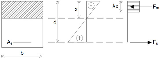
Figure 1.
Stress distribution in masonry elements.
Here (for a rectangular cross-section),
where is the cross-section width, is the effective cross-section height, is the design resistance of the ceramic masonry elements to compression in the direction of the acting load under fire conditions (MPa), and is the design yield strength of steel under fire conditions (MPa).
The fire resistance of a steel ceiling beam depends on its critical temperature. This is the temperature beyond which the beam loses its ability to carry loads. The verification of the fire resistance of such a beam can be performed in the temperature domain in the form of:
where is the beam temperature for a given fire duration, and is the critical temperature of the beam.
Taking into account the fact that steel beams in Klein’s ceilings are not sensitive to instability phenomena, due to the stabilization provided by inter-beam slabs, their critical temperature can be determined as:
where is the capacity utilization rate at the beginning of the fire.
For beams where lateral torsional buckling is not a potential form of failure, the coefficient can be carefully determined by the formula:
where is the reduction factor for design loads in a fire situation (described above), is the partial coefficient for steel under fire conditions (described above), and is the partial coefficient for steel under normal conditions equal to 1.0.
The above formulae are provided with appropriate “θ” indices, which emphasize the members that are reduced by temperature. The calculations required to determine the temperatures of the individual load-bearing elements of the Klein’s ceiling depend on the duration of the fire. This can be determined via temperature profile analyses, which are performed in the numerical part of this study.
5. Numerical Analyses—Klein’s Ceiling Temperature Profiles
To determine the load capacity of Klein’s ceilings under fire conditions, it is necessary to determine the temperature profiles of inter-beam slabs and steel ceiling beams. In the available literature, there are procedures for determining them in a rough way, but there are no detailed methods for determining the exact temperature distribution at the height of the ceiling cross-section. Therefore, this paper presents an original method for determining the temperature profiles of inter-beam slabs and steel ceiling beams based on numerical analyses. In the Abaqus program, nonlinear heat transfer was used because the material properties were temperature-dependent, and the radiation effects always make heat transfer problems nonlinear. Nonlinearities in radiation grow as temperatures increase. Heat transfer analysis is a more specific subset of thermal analysis that focuses on the mathematical modeling and simulation of heat transfer phenomena. It applies the principles of heat transfer to analyze the temperature distribution, heat fluxes, and thermal stresses within a structural system. In this study, the nonlinear heat transfer analysis was carried out for two variants of Klein’s heavy slab, i.e., unplastered and with additional plaster (Figure 2). In addition, the presence of 12 cm thick pudding, 4 cm thick joists and 3 cm thick wooden ceiling boards was taken into account. The numerical models did not include joints between bricks in order to unify them with the cross-section adopted for analytical calculations, in accordance with ref. [17]. The thermal properties of individual elements were set in accordance with refs. [19,20,21]. Numerical models were limited to repeatable systems across the width of the slab. The calculations take into account the impact of a fire described by a standard temperature–time curve. Methods of conducting numerical thermal analyses are included in, e.g., refs. [22,23]. The heat transfer analysis was applied to determine the temperature distribution in the structural members under thermal loading. The transfer of heat from the hot gases into the surface of the Klein’s ceiling, representing the thermal actions, was assumed to comprise a combination of convective and radiative flux. The automatic increment with the maximum number of increments of 7200 was applied. The material behavior was modeled using the conductivity, density, and specific heat temperature-dependent data. The eight-note quadratic heat transfer finite element DC2D8 with mesh control was used. To solve the heat transfer equation, the full Newton technique was applied. The geometry of the numerical model corresponds exactly to that adopted for the analytical example and includes a repeatable Klein’s ceiling cut-out.
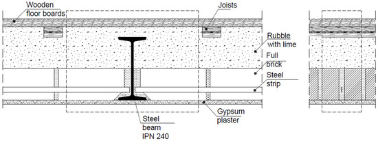
Figure 2.
Analyzed cross-sections; heavy slab.
Figure 3, Figure 4, Figure 5, Figure 6, Figure 7 and Figure 8 presents the temperature profile for the heavy slab of a Klein’s ceiling with and without plaster for a fire duration of 30, 60, and 120 min.
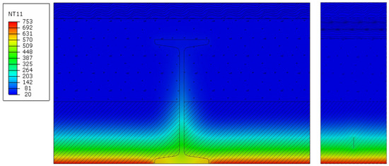
Figure 3.
Temperature profile, heavy slab, without plaster, for a fire duration of 30 min.
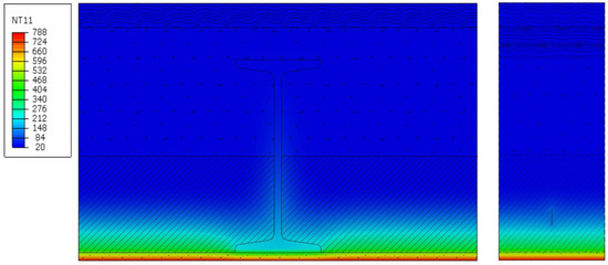
Figure 4.
Temperature profile, heavy slab, with plaster, for a fire duration of 30 min.
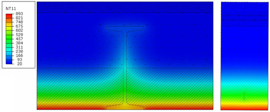
Figure 5.
Temperature profile, heavy slab, without plaster, for a fire duration of 60 min.
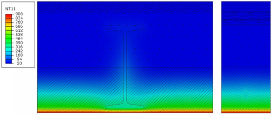
Figure 6.
Temperature profile, heavy slab, with plaster, for a fire duration of 60 min.
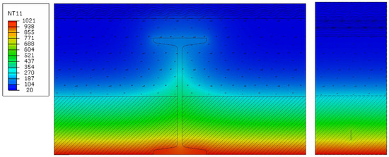
Figure 7.
Temperature profile, heavy slab, without plaster, for a fire duration of 120 min.
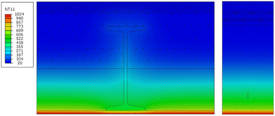
Figure 8.
Temperature profile, heavy slab, with plaster, for a fire duration of 120 min.
On the basis of the results obtained for the heavy slab, the approximate values of temperatures in the load-bearing elements of Klein’s light and heavy/semi-heavy slabs were determined. The analyzed flat Klein’s ceiling consists of I-beams made of steel S235 and inter-beam slabs made of solid bricks, with a compressive strength of 10 MPa, reinforced with steel flat bars made of 1 × 20 mm steel S235. The slab is created by bonding bricks with cement mortar, while the reinforcement is placed in the lower part of the joints approx. 10 mm from the lower edge of the slab and is completely covered with mortar. The slabs are supported on the lower beam flanges. Klein’s floors are built on full formwork. Depending on the arrangement of bricks in the slab, Klein’s floors with slabs of the following types are distinguished: light—bricks laid “flat” (plate thickness 1/4 brick, i.e., 6.5 cm) and heavy—bricks on the entire slab laid “in a seam” (plate thickness 1/2 brick, i.e., 12 cm).
The temperature values that can be used in the calculations for a Klein’s ceiling are shown in the table below. The temperature of the masonry element is taken as the value occurring at the mid-height of the masonry element (in reality, taking into account the permissible limit of compressive strains and tensile strains in the reinforcement outlined in ref. [17], the compression zone of the masonry element will occur above the assumed level). The temperature of the reinforcement and the beam was taken as that occurring at their lower edges. The temperature of the beam was taken as the value occurring at the edge of the bottom flange. Temperature values were rounded up to the nearest 5 °C. A distinction was made between ceilings with plaster and with additional plaster. The variant with plaster refers to an element that was originally made with plaster. The variant with additional render refers to an element that was originally made unplastered and was covered with a layer of render during use. The temperatures of Klein’s ceiling structural elements are presented in Table 3.

Table 3.
Temperatures of Klein’s ceiling structural elements.
The differences in temperature between the variants also appear in the case of the slab reinforcement. Figure 9 shows the temperature measured in the ceiling reinforcement placed at the lower edge of the ceiling for different ceiling constructional solution variants.
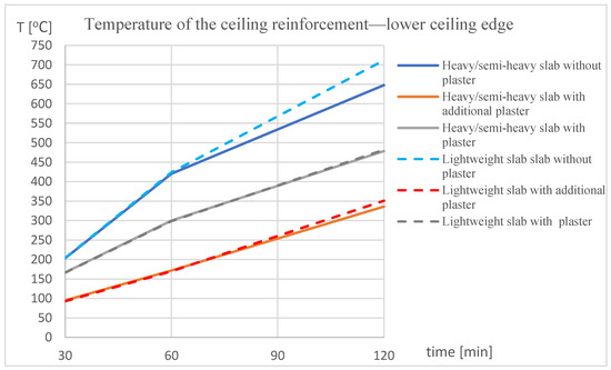
Figure 9.
The temperature–time relation of the ceiling reinforcement placed at the lower edge of the ceiling.
It can be seen that the temperature in the ceiling reinforcement varies depending on the structural variant. The highest temperatures are obtained in the case of ceilings without plaster. Adding additional plaster causes a significant temperature reduction, i.e., in the case of a 120 min fire, a temperature reduction of 600–425 °C to approximately 400 °C is observed. On the other hand, the use of a structural solution with plaster causes the temperature in the 120th minute of the fire to reduce to approximately 340 °C. It can also be seen that the temperature of the reinforcement depends on whether we are dealing with a heavy or light ceiling. In the case of lightweight panels, a higher maximum temperature is obtained in each of the variants of the structural solution. The greatest difference is observed in the case of a ceiling without plaster.
6. Calculation Example for a Selected Klein’s Ceiling Construction Solution
On the basis of the numerical analyses carried out, which yielded temperature profiles that allowed the degree of reduction in the material properties of the ceiling elements to be determined, analytical calculations were carried out for a Klein’s ceiling with a heavy slab and with additional gypsum plaster to a thickness of 1.5 cm (Figure 10), made of solid bricks with a compressive strength of 10 MPa, bonded with M5 cement–lime mortar, reinforced with an S235 steel strip with a 20 × 1 mm cross-section at every second joint (every 16.5 cm), and laid at a distance of 3.0 cm from the bottom edge of the slab (not initially plastered). The floor slab was assumed to be supported by steel beams laid at a spacing of l = 1.2 m. The summary of permanent loads is presented in Table 4 and of variable loads in Table 5. The calculations were performed assuming a slab section width of 1.0 m. The calculations were made assuming a full fire duration, described by a standard 60 min temperature–time curve.
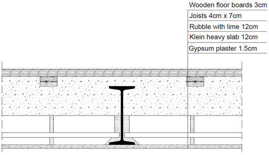
Figure 10.
Analyzed cross-section of a Klein’s heavy slab.

Table 4.
Summary of permanent loads.

Table 5.
Summary of variable loads.
Combination of actions in an exceptional design situation (fire conditions).
Here, is the coefficient for the frequency value of the variable’s impact (Table A 1.1 in ref. [3]).
Calculation effect of actions (bending moment) under fire conditions.
Floor element temperatures.
Reinforcement element temperature—270 °C.
Masonry element temperature—170 °C.
Internal force arm in the slab cross-section.
Here, , , , , .
Design bending resistance under fire conditions.
Load-bearing condition:
Determination of the fire resistance of the beam in the temperature domain.
Beam temperature:
Critical temperature:
Load-bearing condition:
7. Discussion and Comparison
To determine the beneficial impact of plaster, a comparison analysis was performed. The verification of the fire resistance of a typical plastered Klein’s ceiling with a heavy slab, as carried out in this study, has shown that the indicated building element retains its load-bearing capacity for 60 min during a nominal fire. In percentage terms, the load-bearing capacity values of the beam and the ceiling slab are listed in the table below. Such high fire resistance was achieved thanks to the use of plaster. The results of the numerical analysis in the study (Table 6) indicate that, in plastered Klein’s ceilings, the temperature increase in individual elements of the ceiling occurs much slower than in non-plastered ceilings.

Table 6.
The percentage change in load-bearing capacity between heavy slabs with and without plaster, for a fire duration of 60 min.
8. Conclusions
In this study, the load-bearing capacity of a Klein’s ceiling under fire conditions was analytically and numerically analyzed. The analytical and numerical simulations were performed for different structural variants of Klein’s ceilings. A numerical FEM model Abaqus program was developed to create temperature profiles of Klein’s ceilings. The analytical method was used to calculate the fire load capacity of Klein’s ceilings, which were subjected to fire durations of 30, 60, and 120 min. The analytical method for assessing the fire load capacity of Klein’s ceilings uses temperature profiles to produce an analytical method for determining the fire resistance of a Klein’s ceiling, using the authors’ procedure of creating temperature profiles of inter-beam slabs and steel ceiling beams obtained after numerical analyses. The temperature values of the individual structural elements of Klein’s ceilings, depending on the fire duration, are tabulated. The presented procedure then allows calculations to be carried out for different Klein’s ceiling designs.
Based on the determined temperature values of the steel beams, which are the main load-bearing elements of the ceiling, and the critical temperature values θ_(a,cr) contained in ref. [18] depending on the load-bearing capacity utilization factor µ_0, in cases where factor µ_0 > 0.45, the steel beams in unplastered Klein’s ceilings lose their fire load-bearing capacity before the end of the 30 min fire duration, which is defined by the standard temperature–time curve. The use of at least 1.5 cm thick gypsum plaster can ensure the resistance of the above elements for up to 120 min of fire exposure. The quality of the plaster was found to be important, affecting its adhesion to the under-surface of the ceiling.
The fire resistance of inter-beam slabs is significantly influenced by the temperature of their reinforcement, which largely depends on the distance of the reinforcement from the bottom edge of the slab. This is in line with the finding that steel beams in an unplastered Klein’s ceiling lose their fire load-bearing capacity before a 30 min fire duration defined by the standard temperature–time curve. As such, it can be stated that the fire resistance of the steel beam and reinforcement has a significant influence on the entire ceiling’s bearing capacity. The authors believe that a reliable analysis of the fire resistance of Klein’s slabs must be preceded by a thorough inventory and assessment of the technical condition of the ceiling elements, resulting in a detailed characterization of the examined element, including the technical and material solutions used.
Author Contributions
Conceptualization, K.R.; Methodology, K.R.; Formal analysis, B.G.; Writing—original draft, K.R. and B.G.; Writing—review & editing, K.R.; Visualization, B.G. All authors have read and agreed to the published version of the manuscript.
Funding
This research was funded by Poznan University of Technology: 0412/SBAD/0080.
Data Availability Statement
The original contributions presented in this study are included in the article. Further inquiries can be directed to the corresponding author.
Conflicts of Interest
The authors declare no conflict of interest.
References
- Polish Government. Act of 7 July 1994 Polish Construction Law. J. Laws 1994, 89, 414. [Google Scholar]
- Polish Government. Regulation of the Polish Minister of Infrastructure of 12 April 2002 on the technical conditions to be met by buildings and their location. J. Laws 2002, 75, 690. [Google Scholar]
- PN-EN 1990:2004; Eurocode—Basis of Structural Design. Polish Committee for Standardization: Warsaw, Poland, 2004.
- PN-EN 1991-1-2:2006; Eurocode 1: Actions on Structures. Part 1-2: General Actions. Actions on Structures Under Fire Conditions. Polish Committee for Standardization: Warsaw, Poland, 2006.
- Lichołai, L. (Ed.) General Construction. Volume 3: Building Elements. Design Bases: Collective Work. Pod Red. Lichołai L.; Arkady Publishing House: Warszawa, Poland, 2008. [Google Scholar]
- Szumigała, M.; Polus, Ł. Fire resistance of the ceiling in the old tenement house. Procedia Eng. 2017, 195, 178–182. [Google Scholar] [CrossRef]
- Kucz, M.; Rzeszut, K.; Polus, Ł.; Malendowski, M. Influence of Boundary Conditions on the Thermal Response of Selected Steel Members. Procedia Eng. 2013, 57, 977–985. [Google Scholar] [CrossRef][Green Version]
- Król, P. Evaluation of fire resistance of floors on steel beams. BiTP 2014, 35, 73–96. [Google Scholar]
- Maślak, M.; Pazdanowski, M.; Woźniczka, P. Numerical validation of selected computer programs in nonlinear analysis of steel frame exposed to fire. AIP Conf. Proc. 2018, 1922, 150007. [Google Scholar] [CrossRef]
- Seif, M.S.; Weigand, J.M.; Schafer, B.W. Cross-Sectional Stability of I-Shaped Steel Sections at Elevated Temperatures. In Proceedings of the ICTWS 2018, Lisbon, Portugal, 24–27 July 2018; ISBN 978-989-20-8665-1. [Google Scholar]
- Costa, F.C.M.S.; Landesmann, A.; Camotim, D. DSM-Based Prediction of Distortional Failure Load of Cold-Formed Steel Columns at Elevated Temperatures: Influence of the Constitutive Model. In Proceedings of the ICTWS 2018, Lisbon, Portugal, 24–27 July 2018; ISBN 978-989-20-8665-1. [Google Scholar]
- Rzeszut, K.; Polus, Ł. Numerical model of thin-walled purlins restrained by sheeting in elevated temperatures conditions. Arch. Civ. Eng. 2015, 4, 35–46. [Google Scholar] [CrossRef][Green Version]
- Rzeszut, K.; Voronoi, A. Modern design of light steel facades in normal and fire conditions. E3S Web Conf. 2018, 49, 00094. [Google Scholar] [CrossRef]
- Helder, D.C.; Joao, P.C.R.; Aldina, S.; Luis, L. Review of the high temperature mechanical and thermal properties of the steel used in cold-formed steel structures—The case of the S280 Gd+Z steel. Thin-Walled Struct. 2016, 98, 154–168. [Google Scholar]
- Pyrak, S. Nowy Poradnik Majstra Budowlanego; Panas, J., Ed.; Arkady Publishing House: Warsaw, Poland, 2012. [Google Scholar]
- Hoła, J.; Pietraszek, P.; Schabowicz, K. Obliczanie Konstrukcji Budynków Wznoszonych Tradycyjnie; Dolnośląskie Wydawnictwo Edukacyjne: Wrocław, Poland, 2013. [Google Scholar]
- PN-EN 1996-1-1:2010; Eurocode 6. Design of Masonry Structures. Part 1-1: General Rules for Reinforced and Unreinforced Masonry Structures. Polish Committee for Standardization: Warsaw, Poland, 2010.
- PN-EN 1993-1-2:2007; Eurocode 3: Design of Steel Structures. Part 1-2: General Rules—Calculation of Structures for Fire Conditions. Polish Committee for Standardization: Warsaw, Poland, 2007.
- PN-EN 1996-1-2:2010; Eurocode 6: Design of Masonry Structures. Part 1-2: General Rules—Design for Fire Conditions. Polish Committee for Standardization: Warsaw, Poland, 2010.
- PN-EN 1993-1-1:2006; Eurocode 3: Design of Steel Structures. Part 1-1: General Rules and Rules for Buildings. Polish Committee for Standardization: Warsaw, Poland, 2006.
- PN-EN ISO 10456:2009; Building Materials and Products. Thermal and Moisture Properties. Tabulated Design Values and Procedures for Determining Declared and Calculated Thermal Values. Polish Committee for Standardization: Warsaw, Poland, 2009.
- Franssen, J.M.; Vila Real, P. Fire Design of Steel Structures, 2nd ed.; ECCS and Ernst&Sohn: Hoboken, NJ, USA, 2015. [Google Scholar]
- Purkiss, J.A.; Li, L. Fire Safety Engineering Design of Structures, 3rd ed.; CRC Press: Boca Raton, FL, USA, 2013. [Google Scholar]
Disclaimer/Publisher’s Note: The statements, opinions and data contained in all publications are solely those of the individual author(s) and contributor(s) and not of MDPI and/or the editor(s). MDPI and/or the editor(s) disclaim responsibility for any injury to people or property resulting from any ideas, methods, instructions or products referred to in the content. |
© 2025 by the authors. Licensee MDPI, Basel, Switzerland. This article is an open access article distributed under the terms and conditions of the Creative Commons Attribution (CC BY) license (https://creativecommons.org/licenses/by/4.0/).