1. Introduction
High-strength concrete is generally made with a rather high total cementitious content [
1,
2,
3,
4], especially in Hong Kong [
5,
6]. In the Code of Practice for Structural Use of Concrete [
7], i.e., the local concrete code, Clause 4.2.6.1 stipulates that a total cementitious content of up to 550 kg/m
3 is allowed for a concrete grade up to C60 and the total cementitious content may exceed 550 kg/m
3 for a higher concrete grade. As the chemical reactions of the cementitious materials would generate substantial heat during curing, such a high total cementitious content could lead to a very high temperature rise. This could cause the potential problems of delayed ettringite formation and early thermal cracking [
8,
9,
10].
The adiabatic temperature rise of concrete due to the hydration of cement is usually around 13 °C to 15 °C per 100 kg/m
3 of cement, depending on the type of cement and the degree of hydration [
8]. Hence, with a cement content of, say, 450 kg/m
3, the adiabatic temperature rise could be higher than 60 °C. Relatively, the adiabatic temperature rises due to the pozzolanic reactions of PFA (pulverized fuel ash), GGBS (ground granulated blast-furnace slag), and CSF (condensed silica fume) are much lower, and thus, the addition of PFA, GGBS, and/or CSF to replace part of the cement would significantly reduce the adiabatic temperature rise. Clause 4.2.5.5 of the local concrete code actually allows the use of 25% to 35% PFA or 35% to 75% GGBS. However, some engineers in Hong Kong limit the PFA content at a maximum of 20% and the GGBS content at a maximum of 35%. Added with the high total cementitious content to cope with the heavy penalty of non-compliance with strength requirements, the Hong Kong concretes are really hot.
The adiabatic temperature rise of concrete may be estimated from the concrete mix proportions using empirical formulas derived by regression analysis of test results. However, these empirical formulas give only rough estimates because the adiabatic temperature rise is dependent on the characteristics of the materials used for making concrete. For instance, concrete producers in Hong Kong like to use cementitious materials that would yield higher early strength to enable faster construction. Such cementitious materials would generate heat at faster rates, leading to rapid accumulation of heat within massive concrete members and, thus, higher than usual peak temperatures. Hence, the empirical formulas developed elsewhere may not be applicable in Hong Kong. A better way is to measure the actual adiabatic temperature rise by testing. In fact, Clause 10.3.6.1 of the local concrete code stipulates that, for all concrete mixes of a grade higher than C60, adiabatic curing tests should be carried out.
However, it is not easy to conduct an adiabatic curing test, which demands perfect heat insulation at concrete surfaces to inhibit heat dissipation and adaptive control of the surface temperature to minimize the temperature gradient in the concrete [
11,
12,
13]. Due to the difficulties involved, normally, only a semi-adiabatic curing test with a small degree of unavoidable heat dissipation is carried out. Such a semi-adiabatic curing test is called TRET (temperature rise evaluation test). However, the test results of TRET are dependent on the size of the concrete specimen and the thickness of the heat insulation because of the heat loss through the concrete surfaces. Generally, a larger concrete specimen covered with thicker heat insulation would lead to less heat loss per volume and, thus, a smaller testing error. At the moment, there is no standard for TRET, and different engineers adopt different test methods yielding different test results. Nevertheless, the heat loss can be estimated from the rate of temperature drop after the temperature has reached the peak and put back into the concrete to compensate for the heat loss to improve the accuracy of the TRET [
11]. Alternatively, trial casting of a full-scale mock-up could be carried out, and the adiabatic temperature rise could be back-calculated by thermal analysis of the temperature monitoring results.
After estimating the adiabatic temperature rise, thermal analysis is carried out to evaluate the temperature development of the curing concrete, considering the concrete placing temperature, adiabatic temperature rise, ambient temperature, weather condition, heat insulation provided, and internal/external cooling applied. Depending on how complex the shape of the concrete member is, the thermal analysis may be carried out for a simple-shaped member with a uniform section by one-dimensional analysis using the analytical methods given in ACI 207.1R-96 [
14], for an irregular-shaped member with a uniform section by two-dimensional finite element analysis, and for a complex-shaped member with a nonuniform section by three-dimensional finite element analysis. Computer programs are available for such analysis, but before use, validation is needed. The proposed temperature control process and the anticipated weather condition is then simulated, as is demonstrated herein.
To avoid delayed ettringite formation and early thermal cracking, it is necessary to impose certain limits on the peak temperature and the temperature differential within the freshly cast concrete pour [
8,
9]. However, in the local concrete code [
7], there is no mentioning of the temperature control limits to be imposed. As a result, different engineers impose different temperature control limits, and it is uncertain which are more suitable for Hong Kong. Moreover, some engineers are still not aware that the risk of delayed ettringite formation is dependent not only on the peak temperature but also on the types and amounts of supplementary cementitious materials added and that the addition of supplementary cementitious materials can help to lower the risk of delayed ettringite formation and, thus, raise the peak temperature limit for easier temperature control.
The next step is to design the temperature control regime such that the imposed temperature control limits would not be exceeded. It should, however, be noted that the temperature control regimes developed for concrete dams [
14,
15,
16,
17] are mostly not applicable to building structures [
18] and it is necessary to develop specific temperature control regimes for building members because of the following differences: (1) in concrete dams, the concrete mixes are designed to have very low cementitious content and very high PFA content so as to minimize the heat generation, but in building structures, the cementitious content is much higher and the PFA content is at most 35%, and thus, the heat generation can be very large; (2) dams are huge in size, and thus, the boundary surface area to volume ratio and the heat dissipation through boundary surfaces are very small, but in building structures, the heat dissipation through boundary surfaces is quite significant; (3) in building structures, the temperature development is dependent on the minimum dimension of the concrete member, and for relatively small or thin members, the temperature control may be dispensed with if the heat dissipation would reduce the temperature rise to less than about 40 °C.
For the design of the temperature control regimes, the various parameters to be considered include the concrete placing temperature, ambient temperature, surface heat insulation, and internal/external cooling to be applied. Currently, there are still no general guidelines for the design of the temperature control regimes for different weather conditions. What we can do at the moment is to try different parameters and carry out thermal analysis to find out whether any of the temperature control limits would be exceeded. This is rather cumbersome and inefficient. After working on a number of projects on the temperature control of massive high-strength concrete members, it is felt that the presentation of case studies would help to build up experience for guiding the design of temperature control regimes. By the way, a case study on large-diameter bored piles in Hong Kong, revealing that there is a high risk of early thermal cracking in large-diameter bored piles, has recently been published [
19].
Extensive studies [
20,
21,
22] have been carried out to develop systematic techniques for optimizing the structural performance of concrete buildings, but there have been only a few studies for optimizing the thermal performance of temperature control regimes to be applied to curing concrete members. In this paper, a case study in Hong Kong on the thermal analysis and temperature control of C80 concrete with a total cementitious content of 580 kg/m
3 cast into massive columns is presented. The temperature control limits adopted are based on CIRIA C660 [
8] and ACI 201.2R-16 [
9]. Due to the high cementitious content of the concrete and the large size of the columns, internal water-cooling pipes were installed. Full-scale trial casting of a 3.0 m-diameter C80 concrete column was carried out to test the effectiveness of the cooling pipes and to verify the thermal analysis. Then, different cooling-pipe arrangements were tried in the thermal analysis, and the cooling-pipe design was optimized by minimizing the peak temperature and temperature differential within the concrete pour. By the time of writing this paper, all concrete casting of the massive C80 columns has been completed, with no exceedance of temperature control limits and no observable thermal cracks.
3. The C80 Concrete and Massive Concrete Members Cast
The C80 high-strength concrete had a total cementitious content of 580 kg/m
3. It contained 25% PFA and 5.9% CSF. The cement used was an Ordinary Portland Cement of grade 52.5. Both the fine and coarse aggregates used were crushed granitic rock. To attain the required grade strength of 80 MPa, it was designed to have a rather low W/C ratio of 0.25. The QC test results revealed that the actual mean 28-day cube strength was as high as 100 MPa. To achieve the design slump of 200 mm, a fairly high dosage of superplasticizer of more than 9 kg/m
3 (adjustable) was added. Using the design charts given in Section 4.2 of CIRIA C660 [
8], it was estimated that the adiabatic temperature rise of the C80 concrete is about 64.5 °C, and the heat generation per total cementitious content is about 267 kJ/kg. These are, however, only approximate values.
The C80 high-strength concrete columns to be cast include circular columns up to 3.0 m in diameter and noncircular columns up to 2.0 m thick. It was decided right at the beginning that internal water cooling of the curing concrete would have to be provided, but to optimize the design for better constructability, the water-cooling system of each column was separately designed to have the minimum number of cooling pipes because the installation of cooling pipes could cause congestion within the formwork and difficulties in rebar fixing and concrete casting. Then, the cooling pipe arrangement in each column was designed by a trial-and-error process of trying different arrangements and conducting thermal analysis to find out if any of the temperature control limits would be exceeded.
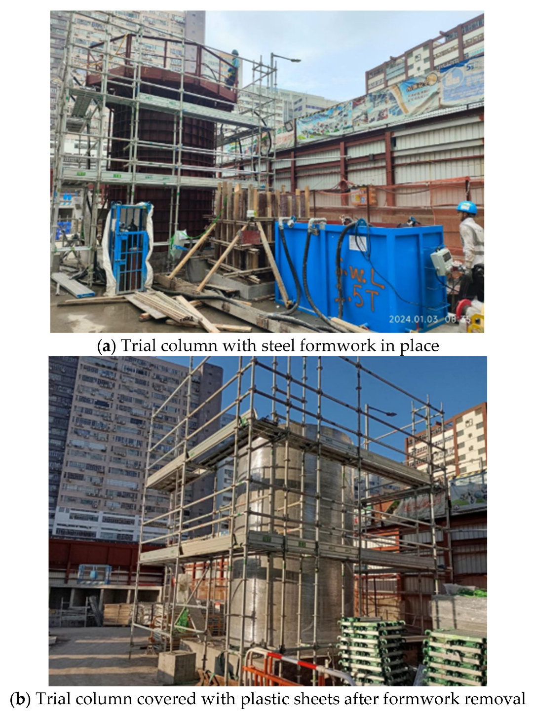
A full-scale trial concrete casting of the biggest 3.0 m-diameter circular column was carried out, as shown in
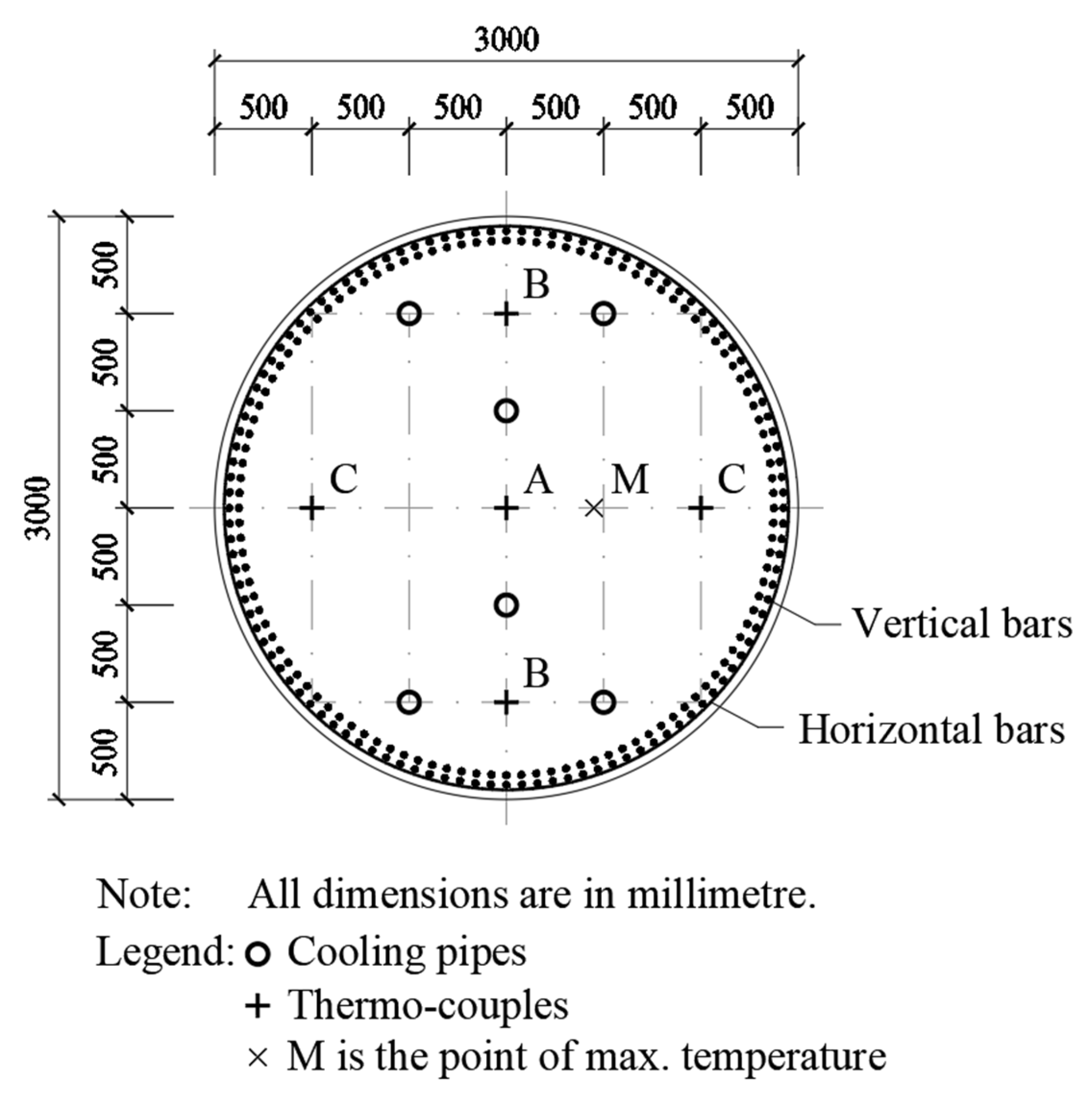
Figure 1, to check the constructability after adding the cooling pipes and to test the effectiveness of the cooling pipes. The trial column was cast to a height of 5.0 m. It was provided with six cooling pipes to draw out the heat and a total of 25 thermo-couples (at five evenly spaced cross-sections and with five in each cross-section) to monitor the temperature distribution and variation with time. Thermal analysis of this trial column by the finite element method was carried out to verify the applicability of the computer program used and to back-calculate the adiabatic temperature rise of the C80 concrete.
Regarding temperature control for avoiding DEF, since the C80 concrete has a PFA content of 25% and a CSF content of 5.9%, the peak temperature limit for avoiding DEF was set as 85 °C. Regarding temperature control for avoiding reduction in strength, since the C80 concrete contains SCM and no heating would be applied, no specific temperature control limit was imposed during the early age (the first 10 h). Nevertheless, six 75 mm-diameter cores were drilled from the trial column cast and tested in accordance with the Hong Kong Construction Standard CS1: 2010 [
27] to find out if there might have been any reduction in strength. The core test results revealed that the in situ equivalent cube strength of the six cores was at least 99.5 MPa, thus confirming that there was no reduction in strength due to high temperatures at the early age. Lastly, regarding temperature control for avoiding early thermal cracking, the temperature differential limit was set as 25 °C, which is more conservative than the recommended value of 28 °C for granite aggregate concrete depicted in Table 7.1 of CIRIA C660 [
8].
4. Thermal Analysis by the Finite Element Method
For thermal analysis of freshly cast concrete, the finite element method is the most versatile [
28,
29]. Since the concrete members to be cast are elongated and have uniform sections, only two-dimensional finite element analysis was carried out. The computer program used was HACON, developed by Lund University [
30]. HACON is a finite element analysis program for simulation of temperature and stress development in hardening concrete. Using HACON, we can estimate the risk of early thermal cracking and find out the most effective measures to avoid crack development. The most updated version of the computer program, HACON 3.1, was used for the thermal analysis. Although this program can also be used to perform post-crack analysis, no post-crack analysis was carried out because it was expected that, with proper temperature control, there should be no early thermal cracking. In fact, our target was to completely eliminate rather than just to minimize early thermal cracking.
Before use, the computer program HACON was first validated by comparing the HACON analysis results of some examples in CIRIA C660 [
8] with the respective values in the design charts presented in CIRIA C660. The examples analyzed were those given in Figure 4.3 and Figure 4.5 of CIRIA C660. All parameters used in the analysis were exactly the same as those in the examples.
Table 1 depicts the comparison between the analysis results obtained by HACON with the respective values in the design charts presented in CIRIA C660. From this table, it can be seen that, on average, the difference in peak temperature is about 1.83 °C, and the difference in temperature differential is about 0.55 °C. Bearing in mind that the values given in the examples and the design charts in CIRIA C660 are not really exact values, such differences were considered small enough to be regarded as admissible. Hence, the HACON passed the validation.
HACON was then used to analyze the trial column cast, with temperature monitoring results available for checking to further verify the applicability and accuracy of the computer program, and the suitability of the parameters used in the thermal analysis. As mentioned before, the trial column was provided with six cooling pipes. Each cooling pipe has an outer diameter of 75 mm. The inlet temperature of the cooling water was controlled at 20 °C by adding ice to the cooling water tank, and the flow rate was adjusted by a valve at the inlet such that the outlet temperature was always kept at around 22 °C. Although the water temperature in each cooling pipe varied between 20 °C and 22 °C, it was assumed to be 21 °C in the thermal analysis. Meanwhile, a total of 25 thermo-couples, five in each cross-section, were installed to monitor the temperature distribution and variation with time. The layouts of the cooling pipes and thermo-couples are shown in
Figure 2.
The material properties of the C80 concrete used in the thermal analysis are summarized in
Table 2. These material properties are either the actual measured values or the estimated values based on CIRIA C660.
On the other hand, the boundary parameters used, which are dependent on the ambient temperature, weather condition, type of formwork before striking of formwork at 48 h, and plastic sheet wrapping provided after removal of formwork at 48 h, are summarized in
Table 3. These parameters are the boundary temperature adopted in the temperature control and the typical thermal conductivity values of the steel formwork and polythene sheets used.
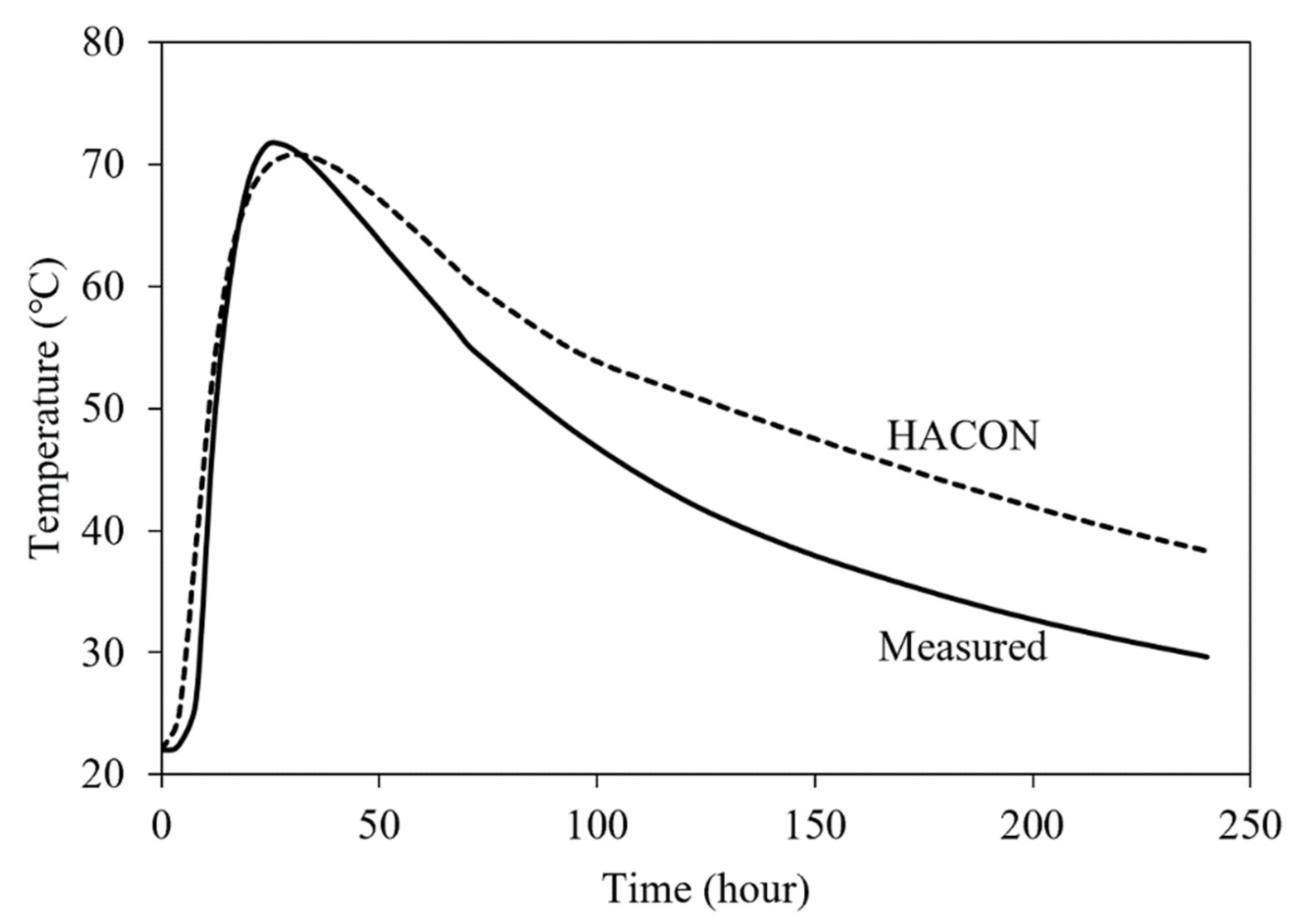
The measured temperature at Point A (center of column section) and the analyzed temperature at Point A by HACON are compared in
Figure 3. It is noted that the measured temperature at Point A increased to 72.2 °C at 25.3 h after casting, whereas the analyzed temperature at Point A by HACON increased to 71.0 °C at 30.6 h after casting. Hence, the measured peak temperature and the analyzed peak temperature agreed quite well with each other. However, the analysis results revealed that the maximum temperature across the column section actually did not occur at Point A but rather at Point M, as marked in
Figure 2, which was at somewhere further away from the cooling pipes than Point A. At Point M, the analyzed peak temperature was 73.6 °C, which was 2.6 °C higher than the analyzed peak temperature at Point A of 71.0 °C. This indicates that temperature monitoring by installing thermo-couples may not give the maximum temperature because the maximum temperature may not occur at any of the thermo-couples installed. Thermal analysis by the finite element method is more useful for determining the maximum temperature across the column section and the maximum peak temperature. On the other hand, the measured maximum temperature differential was 24.0 °C, whereas the analyzed maximum temperature differential was 24.7 °C. Such maximum temperature differentials have not exceeded the allowable limit of 25 °C but seem a bit marginal. It was thus considered better to redesign the cooling pipe arrangement to reduce the temperature differential.
Overall, the analyzed temperature results by HACON agreed quite well with the measured temperature results by the thermo-couples, with an average error of around 1 °C (the order of magnitude of the experimental errors) up to the time the peak temperature was reached. Hence, it is again verified that HACON and the parameters used in the analysis are sufficiently accurate for its intended application of thermal analysis of massive concrete members installed with an internal water-cooling system. Somehow, the error at the post-peak cooling stage was relatively large due partly to the significant variation in ambient temperature during the curing period and partly to the larger than expected heat dissipation after removal of formwork. Nevertheless, the error at the post-peak stage is not critical because the time at which the peak temperature would occur and the time at which the maximum temperature differential would occur have already passed.
Lastly, since the analyzed temperature results and the measured temperature results are already quite close to each other and it appears that the actual adiabatic temperature rise should be just about 1 °C higher than the originally assumed value, it was decided not to carry out the cumbersome back-calculation of the adiabatic temperature rise, which requires iterative adjustment of its value until the best agreement between the analyzed and measured temperature results is achieved. For this particular C80 concrete, the originally assumed adiabatic temperature rise of 64.5 °C and heat generation of 267 kJ/kg estimated using the design charts in CIRIA C660 [
8] are already good estimates.
5. Optimum Design of Temperature Control Regime
The trial column casting and the thermal analysis revealed that the cooling pipes installed are effective in reducing the peak temperature and temperature differential, but the actual effectiveness is dependent on the arrangement and spacing of the cooling pipes. As revealed by the thermal analysis, the point of maximum temperature, i.e., the hottest spot within the column section, generally occurs at somewhere furthest away from the cooling pipes and the boundary surfaces. Hence, it is better to arrange the cooling pipes such that there are no such particularly hot spots. In principle, the cooling pipes should be evenly located such that there is no region in the column section that is too far away from both the cooling pipes and the boundary surfaces. Based on this principle, it was considered that the original six-pipe cooling system was not good and needed to be redesigned.
Another issue is the large difficulty and high cost of lowering the concrete placing temperature to 22 °C. In Hong Kong, the ambient temperature could be higher than 30 °C, and lowering the concrete placing temperature to 22 °C would require the addition of a large amount of ice to the concrete mix and, thus, render the concrete mixing a lot more difficult and the cost of concrete production a lot higher. Hence, consideration should be given to the feasibility of raising the concrete placing temperature to 25 °C or even 30 °C by enhancing the cooling effect of the water-cooling system. Yet another issue is the high cost of providing cooling water at 20 °C for the cooling pipes 24 h a day. This would require the addition of a large amount of ice into the water tanks from which the cooling water is pumped into the cooling pipes. Hence, consideration should also be given to the feasibility of raising the temperature of the cooling water to 25 °C or even 30 °C again by enhancing the cooling effect of the water-cooling system.
After raising the concrete placing temperature and the cooling water temperature to reduce cost, it may be necessary to put in more cooling pipes to increase the effectiveness of the water-cooling system. However, as the installation of more cooling pipes would cause difficulties in rebar fixing and concrete casting, the number of cooling pipes should be kept to the minimum necessary. For instance, for the 3.0 m-diameter column, the number of cooling pipes needs to be increased from six to either seven or eight. To find out the optimal solution, both the seven-pipe cooling system and the eight-pipe cooling system are tried, and their effectiveness in suppressing the peak temperature and temperature differential to avoid non-compliance with the temperature control limits is analyzed by HACON. Then, the complying system with the minimum number of cooling pipes is adopted. For the other massive columns, the same strategy can be applied to design the water-cooling system of each member.
Regarding the number of cooling pipes, one may query how the number of cooling pipes could be an odd number. In the conventional design of cooling pipes, the cooling pipes are arranged in pairs, with each pair comprising an inlet pipe and an outlet pipe. The cooling water flows from the inlet pipe to the outlet pipe through a U-bend connecting the inlet pipe and the outlet pipe together at their far ends. In effect, each pair of cooling pipes is a U-tube, and therefore, the number of cooling pipes is always an even number. This conventional design has the problem that, in some cases, such as the case of the 3.0 m-diameter column, despite the sufficiency of providing seven cooling pipes, we have to provide eight cooling pipes because we cannot put in an odd number of cooling pipes. More importantly, the installation of the U-bends and U-tubes is often obstructed by the rebars, and to avoid conflict, the installation of the U-bends and U-tubes has to be carried out together with the fixing of the rebars. Due to such difficulty in installation of cooling pipes, many engineers do not like internal water cooling and prefer to pay for the higher cost of alternative measures.
In order to overcome the above problems, the construction team has developed an innovative double-pipe design of cooling pipes. In this double-pipe design, each cooling pipe is a double-pipe with a smaller pipe inside the cooling pipe, and the cooling water would flow into the smaller pipe and then out through the annular space between the smaller pipe and the cooling pipe. In effect, both the inflow and outflow of cooling water are through the same cooling pipe, and there are no more U-bends. This would allow the rebars to be fixed first and then the cooling pipes to be inserted into the rebar cage for installation at a later time. Hence, there is the major advantage of a much easier and faster installation. Moreover, the number of cooling pipes can now be an odd number for better optimization. This double-pipe design is, at the moment, patent pending, and no further details can be given here.
Regarding the optimum design of temperature control regime, it was just by means of a trial-and-error process of trying different concrete placing temperatures, different cooling water temperatures, and a different number and arrangement of cooling pipes, and conducting thermal analysis to find out if satisfactory results could be obtained. To cater for concrete casting over several months under moderate or hot weather conditions, the thermal analysis was carried out twice, with the ambient temperature set first as 20 °C in moderate weather and then as 30 °C in hot weather. After several rounds of thermal analysis, it was decided to raise the concrete placing temperature to 30 °C and the cooling water temperature to 25 °C in order to reduce cost. Afterwards, the number of cooling pipes was varied to find out the minimum number needed to comply with the temperature control limits.
Frankly speaking, the above iterative optimization process is quite cumbersome and time consuming. In the longer term, further research should be carried out to establish design guidelines for quicker choices of concrete placing temperature, cooling water temperature, number of cooling pipes, spatial arrangement of the cooling pipes, etc. Consideration should also be given to the possibility of developing a fully computerized and automated method for the design of temperature control regimes. The use of artificial intelligence for this purpose could be an interesting and impactful research project.
Some of the optimum designs so arrived at are depicted in
Figure 4 and
Figure 5 for circular section columns,
Figure 6 and
Figure 7 for rectangular section columns, and
Figure 8 and
Figure 9 for irregular section columns. In these designs, the locations and spacings of the cooling pipes have been adjusted iteratively by small steps until the peak temperature and temperature differential values are minimized for best overall thermal performance. The minimized values so attained of the peak temperature and temperature differential within each column section under the moderate and hot weather conditions are presented in each of these figures to elucidate the ample margins provided in each column section for ensuring compliance with the temperature control limits.
From
Figure 4, it can be seen that, for a 3.0 m-diameter circular section column, the provision of seven symmetrically arranged cooling pipes, with six located at the vertices of a hexagon and one located at the center of the section, is already sufficient for complying with the temperature control limits. Compared to an earlier scheme of providing eight cooling pipes, the number of cooling pipes has been reduced by one. In
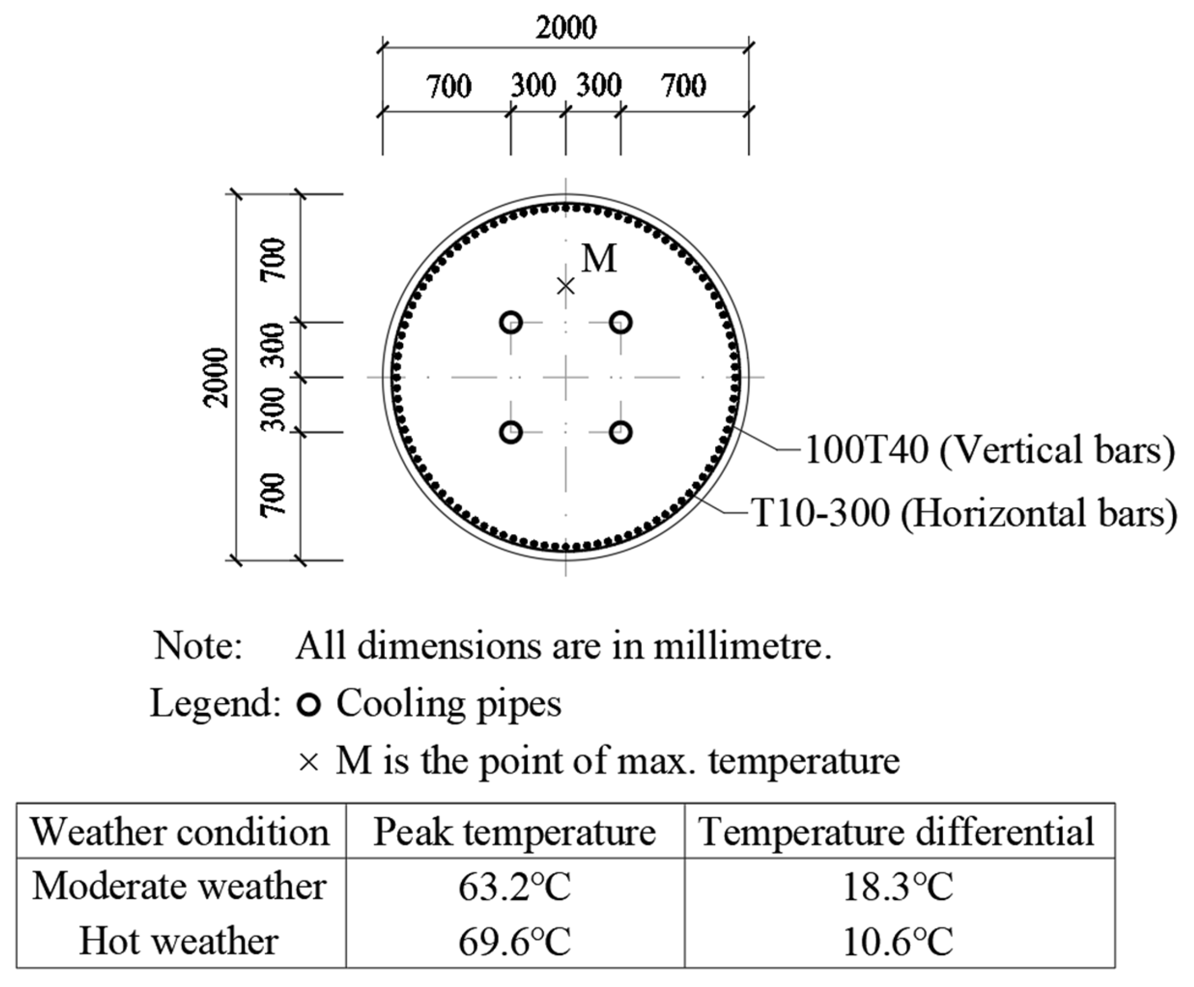
Figure 5, it can be seen that, for a 2.0 m-diameter circular section column, the provision of four symmetrically arranged cooling pipes located at the vertices of a square is already sufficient.
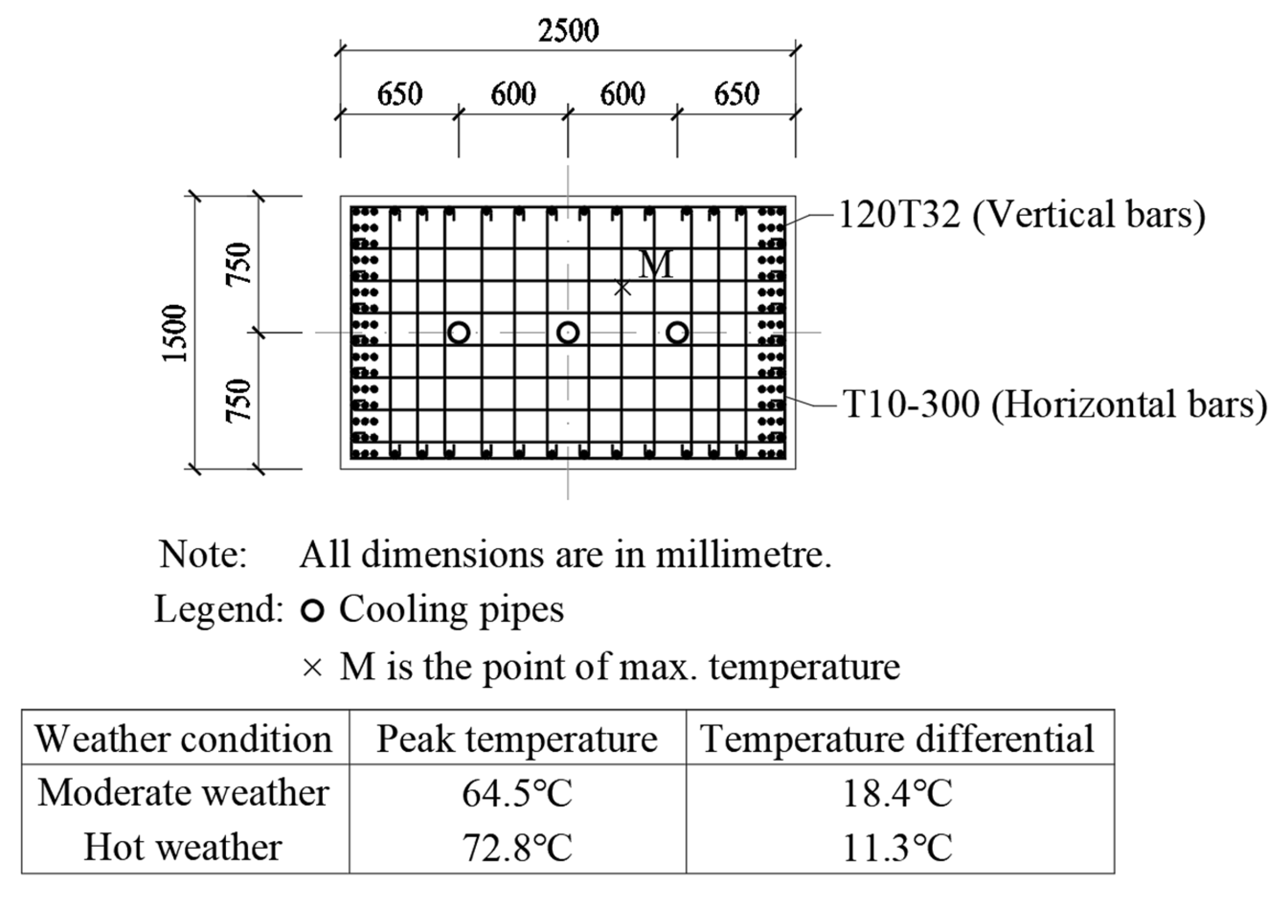
In
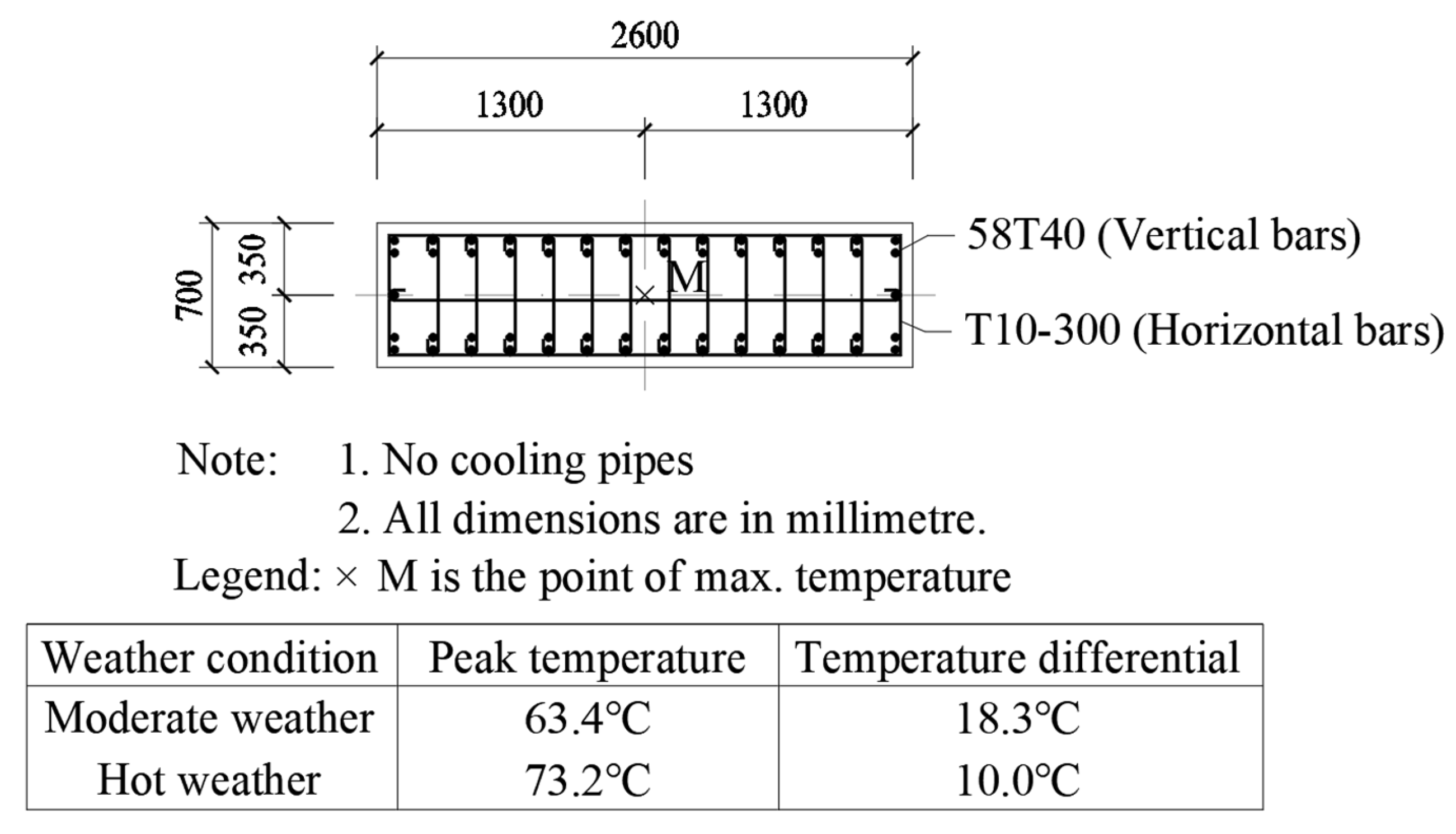
Figure 6, it can be seen that, for a 1.5 m-thick rectangular section (2.5 m × 1.5 m) column, three evenly spaced cooling pipes along the longer axis need to be provided for complying with the temperature control limits. In
Figure 7, however, it can be seen that, for a 0.7 m-thick rectangular section (2.6 m × 0.7 m) column, no cooling pipe needs to be provided. Hence, for rectangular section columns, the thickness is the governing factor in the design of the water-cooling system. In fact, it has been found that all the rectangular section columns with a thickness ≤ 0.7 m do not need any cooling pipe.
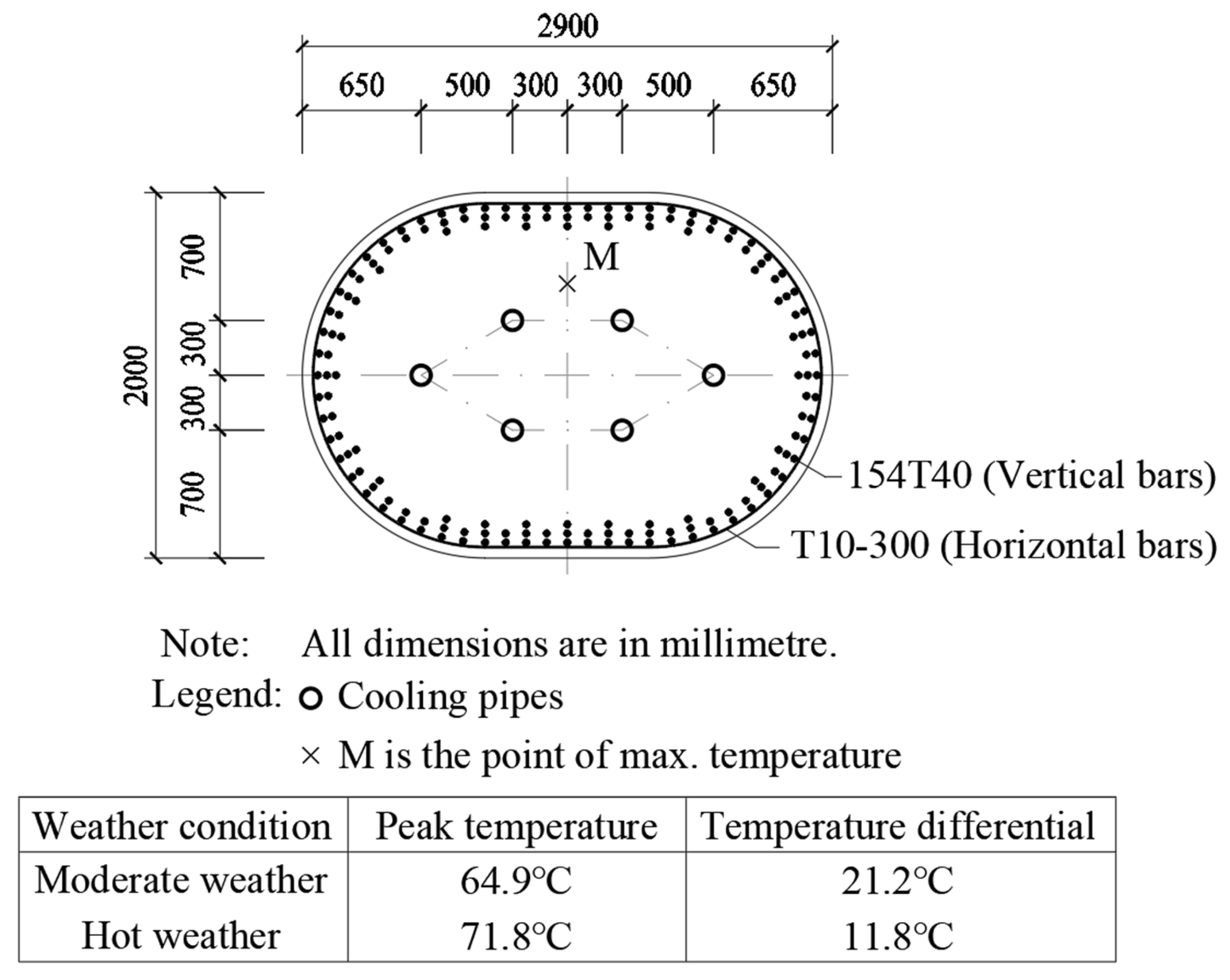
In
Figure 8, it can be seen that, for a 2.0 m-thick irregular section (2.9 m × 2.0 m) column whose section comprises a rectangle and two semi-circles, six cooling pipes need to be provided for complying with the temperature control limits. In
Figure 9, it can be seen that, for a 1.6 m-thick irregular section (2.4 m × 1.6 m) column whose section comprises a rectangle and two semi-circles, four cooling pipes need to be provided. The experience gained is that, without thermal analysis by the finite element method, it is almost impossible to work out these optimum designs for irregular section columns.
One important point to note is that the above specifically designed temperature control regimes are only for concrete casting under moderate or hot weather conditions because these are the weather conditions that would be encountered during concrete casting. For concrete casting under cold weather conditions, the temperature control regimes need to be redesigned. Basically, for cold weather concreting at an ambient temperature of around 10 °C, the concrete placing temperature and the cooling water temperature should be set lower. Actually, at an ambient temperature of around 10 °C, there is no need to add ice anymore, and thus, lowering the concrete placing temperature and the cooling water temperature would not incur additional cost. The design of temperature control regimes for cold weather concreting may follow the same steps as for moderate and hot weather concreting as demonstrated herein.
Another important point to note is that bad weather, such as heavy rain and strong wind, could cause rapid surface cooling of the columns and thus increase the temperature differential between the maximum temperature within the column section and the surface temperature at the column section. Hence, at times of bad weather, the freshly cast columns should be protected by covering with polythene sheets sealed at their edges.
6. Lessons Learned and Discussions
The above internal water-cooling systems, optimally designed with the help of thermal analysis by the finite element method, have been implemented for temperature control of the massive C80 concrete columns, and the casting and curing of the concrete columns were all completed. After scrutiny of the temperature monitoring records and close inspection of the finished concrete columns, it was confirmed that there was no exceedance of temperature control limits and no observable early thermal cracks. So, the internal water-cooling systems performed satisfactorily. This was achieved after raising the concrete placing temperature to 30 °C and the cooling water temperature to 25 °C to reduce cost. Such cost savings were made possible by rearranging the cooling pipes to be more evenly located to avoid having hot spots in the concrete sections so as to enhance their effectiveness. The optimization methodology developed herein may be considered as a basis for the design of temperature control regimes and internal water-cooling systems for the casting and curing of massive high-strength concrete elements of grade C80 and up to a cross-section size of 3.0 diameter.
Another achievement is the development of a double-pipe design of cooling pipes. With this design, each cooling pipe has a smaller pipe inside so that the cooling water would flow into the smaller pipe and then out through the annular space between the smaller pipe and the cooling pipe. As both the inflow and outflow of cooling water are through the same cooling pipe, U-bends are not needed anymore, and each cooling pipe is a straight pipe, which can be inserted into the rebar cage after rebar fixing. This allows easier and faster installation and the number of cooling pipes to be an odd number for better optimization.
While celebrating the success of the above temperature control regimes, it is felt that there is still room for improvement. Actually, the key factor is the heat generation of the concrete. If the C80 concrete could be redesigned to have lower total cementitious content and higher PFA content, its heat generation could be reduced to ease the temperature control. There are many ways to do so. Firstly, volumetric proportioning should be adopted for more accurate proportioning in order to achieve better optimization, as Domone and Soutsos suggested [
1]. Secondly, the packing density of the aggregate should be optimized by aggregate proportioning to reduce the volume of voids to be filled with paste so as to reduce the paste volume and total cementitious content [
31]. Thirdly, more PFA or GGBS should be added to reduce the cement content and the heat generation. It has been found that the use of 45% PFA to produce high-strength concrete could substantially reduce the heat generation [
32]. Such a PFA content of 45% may seem a bit too high, but increasing the PFA content to the allowable limit in the local concrete code of 35% would already significantly reduce the heat generation. Lastly, there is also an effective method of adding a powder filler to reduce the cementitious paste volume, total cementitious content, and heat generation [
33,
34].
Regarding whether the proposed temperature control regimes may also be applied to massive concrete elements cast of C100 concrete, the basic principles for designing the temperature control regimes are the same, and the methodologies developed herein, such as the finite element analysis method and the internal water-cooling method, should also be applicable to C100 concrete. It is only that C100 concrete usually has a higher total cementitious content and, thus, would generate more heat. Hence, the temperature control of C100 concrete is more difficult and critical. Chances are that more ice would be needed to lower the concrete placing temperature to say 25 °C, more cooling pipes would be needed, and cooler water would have to be used for the internal water cooling. But first of all, effort should be made to reduce the total cementitious content of the C100 concrete so that less heat would be generated.
