Article

Theoretical and Experimental Evaluations on Cooperative Bending Behavior of Laminated Channel Beams in Modular Steel Buildings

1
Shandong Electric Power Engineering Consulting Institute Corp., Ltd., Jinan 250013, China
2
JiangSu Key Laboratory of Environmental Impact and Structural Safety in Engineering, China University of Mining and Technology, Xuzhou 221116, China
3
School of Architecture and Construction, Jiangsu Vocational Institute of Architectural Technology, Xuzhou 221116, China
4
School of Civil Engineering, Zhengzhou University, Zhengzhou 450001, China
5
School of Urban Construction, Changzhou University, Changzhou 213164, China
*
Author to whom correspondence should be addressed.
Buildings 2025, 15(23), 4221; https://doi.org/10.3390/buildings15234221 (registering DOI)
Submission received: 4 September 2025 / Revised: 24 October 2025 / Accepted: 11 November 2025 / Published: 22 November 2025
(This article belongs to the Special Issue Advances in Structural Techniques for Prefabricated Modular Buildings)

Abstract

Modular steel buildings that employed off-site prefabricated volumetric units offered advantages in construction speed and sustainability. The highly integrated buildings assembled by only column-to-column connections were prone to a global collapse, and beam-to-beam connections could greatly promote the overall mechanical performance. However, cooperative bending performance has not been fully understood from a theoretical perspective, and therefore, a performance-based structural design cannot be conducted in practical engineering. In the present study, the laminated double beams in modular steel buildings were theoretically and experimentally investigated. Theoretical models for interfacial slip strain and slippage were established based on differential equations, accounting for both frictional and bolted connection types. In addition, mathematical expressions for bending curvature incorporating interfacial slip were derived, leading to a theoretical procedure for calculating the equivalent initial bending stiffness. In this way, the mechanical performance of laminated beams was analyzed, and the superimposed bending effect was further evaluated. The results demonstrated that bolted connections improved bending capacity by approximately 8% and increased initial bending stiffness by 17–28% compared to friction-only connections. The proposed stiffness prediction models showed significant agreement with experimental data, providing a theoretical basis for the structural design of laminated beams in modular steel buildings.

1. Introduction

Modular steel buildings use standardized room modules for design, industrial production, and integrated decoration. The modules are transported to the site for assembly, forming the complete buildings [1,2,3,4,5,6]. This method has been shown to improve prefabrication rates, shorten construction times, and reduce environmental pollution, while meeting the demands of building industrialization [7,8,9,10,11,12,13]. Due to their construction advantages, modular steel buildings have been widely used in temporary buildings, hospitals, office buildings, and dormitories in recent years.
In highly integrated modular steel building systems, the coupled connections between modular units exhibit a significant influence on the overall mechanical performance. Traditional modular connection techniques typically involve assembling modules by welding or bolting at the corner column-to-column joints, with these column-to-column connections responsible for bearing and transferring external loads. Several authors have conducted investigations on the mechanical performance of modular steel building systems and substructures with only corner constraints. Mostafaei et al. comprehensively investigated seismic resilience and sustainability [14]. The results indicated that, under seismic loading, the column-to-column connections between modules were prone to stress concentration and the development of plastic hinges, which may ultimately lead to the loss of overall robustness in the modular structural system. Enhancing the degree of modular joint connection could improve the mechanical coupling between modules; however, the structural ductility still failed to meet the desired design objectives.
To improve the overall stability of modular steel buildings, researchers have proposed establishing mechanical connections between adjacent double beams of upper and lower modules. This approach increases the load transfer paths within the modular steel buildings and enhances the mechanical restraint between modular units. Li et al. [15,16] designed an interfacial connector for adjacent double beams and conducted two-point concentrated load tests. The experimental results showed that the laminated double beams in modular steel buildings generally conformed to the plane section assumption. Moreover, the overall integrity of the connector’s cross-section exhibited superior mechanical performance compared to discontinuous cross-sections, and this advantage became increasingly evident as the applied load increased. Chang et al. [17] proposed a web-bolted connection for laminated double beams and investigated their flexural mechanical performance. The results indicated that, in laminated steel beams, the floor beam is subjected to compressive bending while the ceiling beam experiences tensile bending. The shear connection between the double beams effectively enhances the overall flexural stiffness and load-bearing capacity of the laminated steel beam. Compared to independent double beams, laminated steel beams can save approximately 15% of steel. By considering the composite effect of adjacent double beams, the cross-sectional dimensions of floor beams and ceiling beams in modular steel buildings can be reasonably reduced. Zhang et al. [18,19] enhanced the synergy between horizontally adjacent channel beams in modular steel buildings by installing bolt connections through the webs of back-to-back double channel beams, thereby forming laminated channel beams. They further investigated the overall flexural performance of these laminated channel beams. Zha et al. [20,21] investigated the reliability of force transmission in corner joints composed of gusset plates and high-strength bolts in modular prefabricated buildings and proposed internal force calculation formulas for double-beam and double-column steel frame systems. Zhu et al. [22] conducted the bending tests on bolted laminated double beams. The experimental results showed that the laminated interface also serves as a longitudinal stiffener, which improved the local stability of the member. In addition, using thinner and higher-strength steel in the tension zone can enhance economic efficiency. Xu et al. [23,24,25,26,27] proposed a modular bolted laminated double channel beam structure and conducted studies on its flexural mechanical performance. The results showed that, under mutual mechanical constraints, the laminated double beams exhibit significantly improved bending capacity and stiffness compared to independent double beams. The existing studies preliminarily investigated the flexural performance of bolted laminated double beams in modular steel buildings and established mechanical models for strength and stiffness. However, they did not conduct theoretical deflection analysis from a mechanical perspective for such non-continuous point-connected composite beams, making it difficult to provide a reliable theoretical basis for their structural design. In addition, it was noted that the existing evaluations mainly focus on the initial bending stiffness of the mid-span section of the modular laminated steel beams, which provides the design criterion for the bearing capacity of local positions but makes it hard to provide theoretical calculations for global structural behaviors.
For this purpose, it is necessary to explore the deformation development of modular laminated beams along the whole span direction and promote the fine design of this innovative component based on the performance of the whole process. In this study, theoretical and experimental investigations were conducted on the mechanical behavior of bolted point-connected laminated beams in modular steel buildings. The cooperative flexural behavior of the composite beams was analyzed. Based on previous work on the fundamental differential equation of double-beam curvature and the interfacial slipping model, a theoretical deflection analysis was carried out. An analytical model for the deflection curve of simply supported composite double beams under typical loading conditions was derived, providing a theoretical basis for the design of such novel laminated beam structures.

2. Design of Laminated Beam Structures in Modular Steel Buildings

According to the Load Code for the Design of Building Structures [28], the design loads for the floor beams and ceiling beams in modular steel buildings were determined. Then, the structural design of floor and ceiling beam components was carried out for a standard modular unit with dimensions of 6 × 3 × 3.1 (m × m × m), referencing the Standard for Design of Steel Structures and the Handbook for the Design of Modular Structures. As a result, the floor beam (FB) and ceiling beam (CB) were selected as cold-formed channel steel members with cross-sectional dimensions of 300 × 150 × 6 mm and 200 × 150 × 6 mm, respectively, as shown in Table 1 and Figure 1. To investigate the flexural performance of laminated steel beams with different interfacial connections, two friction-laminated beam specimens with only friction restraints and two bolt-laminated beam specimens were designed. In the friction-laminated beam specimens (named LFCB), the floor beam (FB) and ceiling beam (CB) were simply superimposed, with only tangential friction acting at the interface under vertical loading. Moreover, another friction-laminated double beam specimen with floor beams (FBs) of equal height was designed and designated as LFFB, aiming to evaluate the height of single beams. Under the same dimensional and structural conditions, four high-strength bolts were installed at the interface at intervals of 1050 mm to form bolted laminated steel beam specimens, designated as LFCB-4B and LFFB-4B, respectively. The specimen configurations are shown in Figure 1.

3. Theoretical Analysis of the Synergistic Flexural Deflection Curve of Laminated Channel Beams in Modular Steel Buildings

3.1. Theoretical Analysis Strategy for the Laminated Beams in Modular Steel Buildings

A theoretical analysis of the deflection curve for modular laminated steel beams was conducted to provide the foundation for practical engineering design. It was noted that during the cooperative bending behaviors of the double-beam structures, the relative slipping occurred between the floor beam and the ceiling beam, which significantly affected the overall mechanical performance of laminated beams in modular steel buildings. Hence, based on the fundamental differential equations of double-beam curvature, the theoretical model for interfacial slip was derived and then the analytical model for the deflection curve of laminated double beams could be further developed. By combining the fundamental differential equation for the flexural behavior of laminated steel beams with the basic physical equation for slip strain at the interfacial surface of double beams, the differential control equation for relative slip in laminated steel beams was derived, thereby establishing theoretical models for relative slip under various loading conditions, boundary conditions, and degrees of interfacial connection. The following fundamental assumptions were made for the composite flexural behavior of double-beam structures: (1) both the floor beam and the ceiling beam are assumed to be elastic for serviceability limit state design, and the deflection and end rotation remain within the small deformation range; (2) the floor beam and ceiling beam exhibit the same curvature in the laminated beam, with the vertical connection physically enforced by the high-strength bolts, with no relative vertical displacement between the upper and lower layers; (3) shear deformation of both beams is neglected, and both the upper and lower beams satisfy the plane section assumption; (4) the shear connection at the interface between the floor beam and ceiling beam is uniformly distributed along the beam span considering the perfectly ductile and uniformly spaced bolt connections, and the tangential distributed load at the interface is proportional to the relative slip between the beams.
Firstly, the interfacial slip strain s’(x) was analytically calculated and the theoretical expressions for the interfacial slip were developed. A mathematical expression for the curvature of modular laminated double beams, considering the relative slip, was derived. Taking into account the simply supported boundary conditions of the laminated double beams, accurate analytical solutions for the deflection w(x) and rotation w’(x) of the laminated steel beams considering interfacial slip can be obtained. Consequently, theoretical load-deflection models for laminated steel beams under various loading conditions and boundary conditions were established.
For pure friction laminated double beams, the interlayer effect resulting from friction is not considered in this study. According to assumption (2), the principle of equal curvature, the theoretical stiffness value for pure friction laminated double beams can be expressed as follows:
E I 0 = E I f + E I c
According to the flexural formula for beams, the curvature distribution of a laminated double beam under bending, neglecting shear deformation, can be expressed as:
w ( x ) = M ( x ) E I 0
For the laminated beams that are point-connected, the combination effect resulting from friction was also not considered. The shear stiffness at the interface between the beams was significantly increased, which resulted in the development of axial forces in both the floor beam and the ceiling beam. Consequently, the upper and lower beams were subjected to a combination of axial force and bending moment. Let Nf(x) denote the axial force in the floor beam and Nc(x) denote the axial force in the ceiling beam. The static equilibrium equations for the upper and lower beams can thus be expressed as:
N f ( x ) + N c ( x ) = 0
The tangential distributed load at the interface was proportional to the relative slip between the beams. According to the sectional internal force equilibrium condition, the following relationship can be obtained:
N f ( x ) = t ( x ) = K S ( x )
V f ( x ) = q ( x ) + r ( x )
M f ( x ) = V f ( x ) + t ( x ) h f / 2
N c ( x ) = t ( x ) = K S ( x )
V c ( x ) = r ( x )
M c ( x ) = V c ( x ) + t ( x ) h c / 2
V ( x ) = q ( x )
M ( x ) = V ( x )
Based on the internal force equilibrium condition of the cross-section, the internal force equilibrium equation for the laminated steel beam can be established as follows:
V f ( x ) + V c ( x ) = V ( x )
M ( x ) = M f ( x ) + M c ( x ) N f ( x ) h 0
where Mf(x) and Mf(x) denote the bending moments of the floor beam and the ceiling beam, respectively, and h0 represents the distance between the neutral axes of the floor beam and the ceiling beam.
According to assumption (2), the floor beam and ceiling beam in the laminated steel beam exhibit the same curvature. In combination with the relationship between the bending moment and curvature, the following expression can be obtained:
w ( x ) = M f ( x ) / E I f
w ( x ) = M c ( x ) / E I c
w ( x ) = [ M ( x ) + N f ( x ) h 0 ] / E I 0
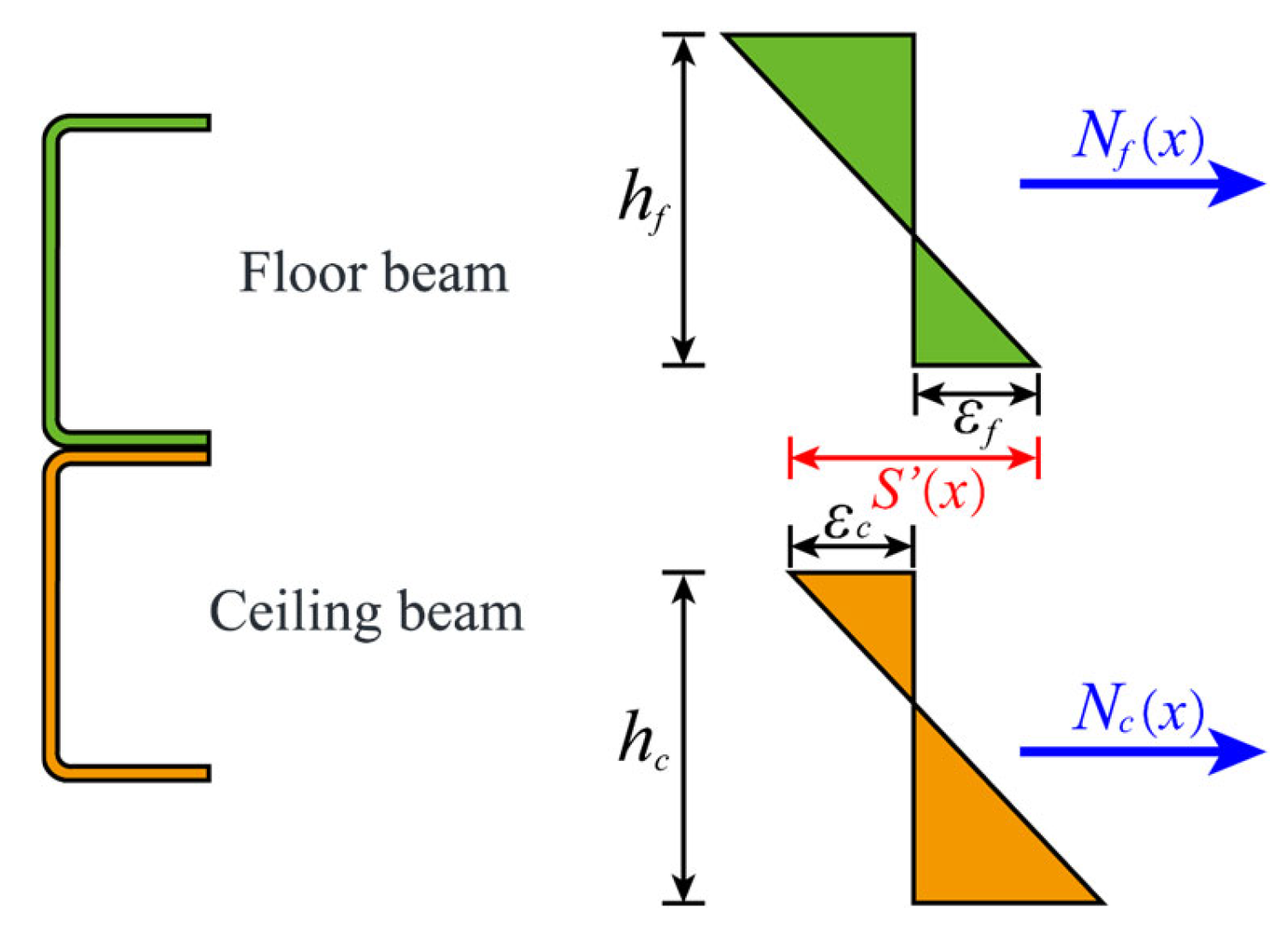
The relative slip behavior at the interface was a key factor influencing the composite flexural effect between the floor beam and the ceiling beam. Compared with an integral beam structure, the laminated double-beam structure develops a certain amount of slip strain at the interface, as shown in Figure 2.
According to the internal force–strain relationship of the laminated steel beam cross-section, the following can be obtained:
N f ( x ) = E A f [ w ( x ) h f / 2 + ε f ]
N c ( x ) = E A c [ w ( x ) h c / 2 + ε c ]
S ( x ) = ε f ε c
Furthermore, the analytical equation for the slip strain at the interface can be obtained as follows:
S ( x ) = N f ( x ) EA f N c ( x ) EA c w ( x ) h f / 2   w ( x ) h c / 2 = N f ( x ) EA f N c ( x ) EA c + M ( x )   +   N f ( x ) h 0 E I 0 h 0
By incorporating the following formula and differentiating the above equation, we have:
S ( x ) α 2 S ( x ) = V ( x ) h 0 / E I 0
α = K h 0 2 E I 0 ( 1 E I 0 / E I )
Based on the above, the curvature formula for laminated steel beams considering the relative slip between the floor beam and the ceiling beam can be derived as follows:
w ( x ) = M ( x ) E I ( 1 E I 0 E I ) S ( x ) h 0

3.2. Theoretical Model of the Deflection Curve for Laminated Beams with Only Friction Restraints in Modular Steel Buildings

For the laminated beams with only friction restraints in modular steel buildings, the two single layers were simply coupled and undertook the external loads solely, without significant additional axial forces developing in the cross-sections of the upper and lower beams. Therefore, the mathematical expression for the curvature of the double-beam structure was given by Equation (24).
w ( x ) = M ( x ) EI 0
w ( x ) = P E I 0 ( x 2 + L 4 ) x [ L / 2 ,   a ) w ( x ) = P E I 0 ( L 4 a 2 ) x [ a ,   a ] w ( x ) = P EI 0 ( x 2 L 4 ) x ( a ,   L / 2 ]
Based on the boundary conditions of the simply supported laminated steel beam, the analytical model for the deflection curve of a simply supported pure friction laminated steel beam under symmetrically applied two-point concentrated loads can be obtained as follows:
w ( x ) = P E I 0 ( x 3 12 + L 8 x 2 + a 4 x + a 2 L 8 L 3 48 ) x [ L / 2 ,   a ) w ( x ) = P E I 0 ( L 8 x 2 a 4 x 2 a 3 12 L 3 48 + a 2 L 8 ) x [ a ,   a ] w ( x ) = P E I 0 ( x 3 12 L 8 x 2 + a 4 x a 2 L 8 + L 3 48 ) x ( a ,   L / 2 ]

3.3. Theoretical Model of the Deflection Curve for Laminated Double Beams That Are Point-Connected in Modular Steel Buildings

The high-strength bolts effectively enhanced the mutual constraint between the beams, resulting in additional axial forces in the cross-sections of the floor and ceiling beams. Therefore, the mathematical expression for the curvature of laminated beams that are point-connected in modular steel buildings was given by Equation (27). Previous studies have systematically analyzed the relative slip of laminated beams in modular steel buildings and established a theoretical slip model for simply supported laminated steel beams that are point-connected under symmetrically applied two-point concentrated loads. By substituting the theoretical expression for slip strain into Equation (27), the higher-order differential control equation for the deflection curve of the double-beam structure can be obtained, as shown in Equation (28).
w ( x ) = M ( x ) E I ( 1 E I 0 E I ) S ( x ) h 0
w ( x ) = P EI ( x 2 + L 4 ) P φ   cosh ( α a ) ( e α L + α x e α x ) 2 α EI ( e α L + 1 ) x [ L / 2 ,   a ) w ( x ) = P EI ( L 4 a 2 ) P φ ( e α L α a e α a ) ( e α x + e α x ) 4 α EI ( e α L + 1 ) x [ a ,   a ] w ( x ) = P EI ( x 2 L 4 ) P φ cosh ( α a ) ( e α L α x e α x ) 2 α EI ( e α L + 1 ) x ( a ,   L / 2 ]
Based on the boundary conditions of the simply supported laminated beam, the analytical model for the load–deflection curve of a simply supported laminated beam in modular steel buildings under symmetrically applied two-point concentrated loads can be obtained as follows:
w ( x ) = P EI ( x 3 12 + L 8 x 2 + a 4 x + a 2 L 8 L 3 48 ) P φ cosh ( α a ) ( e α L + α x e α x ) 2 α 3 EI ( e α L + 1 ) + P φ ( 2 x + L ) 4 α 2 EI x [ L ,   a ) w ( x ) = P EI ( L 8 a 4 ) x 2 a 3 12 L 3 48 + a 2 L 8 P φ ( e α L α a e α a ) cosh ( α x ) 2 α 3 EI P φ ( 2 a L ) 4 α 2 EI x [ a ,   a ] w ( x ) = P EI ( x 3 12 L 8 x 2 + a 4 x a 2 L 8 + L 3 48 ) P φ cosh ( α a ) ( e α L α x e α x ) EI 2 α 3 ( e α L + 1 ) P φ ( 2 x L ) 4 α 2 EI x ( a ,   L ]

3.4. Theoretical Model of the Deflection Curve for Pure Friction Laminated Beams with Fixed Supports in Modular Steel Buildings

Under symmetrically applied two-point concentrated loads, the higher-order differential control equation for the relative slip deflection curve of a fixed-end pure friction laminated steel beam is given by Equation (30):
w ( x ) = P EI 0 ( x 2 + L 8 + a 2 2 L ) x [ L / 2 ,   a ) w ( x ) = P EI 0 ( L 8 + a 2 2 L a 2 ) x [ a ,   a ] w ( x ) = P EI 0 ( x 2 L 8 a 2 2 L ) x ( a ,   L / 2 ]
Furthermore, based on the boundary conditions, the analytical model for the load–deflection curve of a fixed-end pure friction laminated steel beam can be derived as follows:
w ( x ) = P EI 0 x 3 12 + ( L 16 + a 2 4 L ) x 2 + a 2 4 x + a 2 L 16 L 3 192 x [ L / 2 ,   a ) w ( x ) = P EI 0 ( L 16 + a 2 4 L a 4 ) x 2 a 3 12 + a 2 L 16 L 3 192 x [ a ,   a ] w ( x ) = P EI 0 x 3 12 ( L 16 + a 2 4 L ) x 2 + a 2 4 x a 2 L 16 + L 3 192 x ( a ,   L / 2 ]

3.5. Theoretical Model of the Deflection Curve for Point-Connected Laminated Beams with Fixed Supports in Modular Steel Buildings

Under symmetrically applied two-point concentrated loads, the higher-order differential control equation for the deflection curve of a fixed-end point-connected laminated steel beam considering an interlayer slip is as follows:
w ( x ) = P EI ( x 2 + L 8 + a 2 2 L ) P φ [ ( e α L / 2     e α L cosh ( α a ) ) e α x   +   ( e α L / 2     cosh ( α a ) ) e α x ] 2 α EI ( e α L 1 ) x [ L / 2 ,   a ) w ( x ) = P EI ( L 8 + a 2 2 L a 2 ) P φ ( e α L α a     2 e α L / 2   +   e α a ) cosh ( α x ) 2 α EI ( e α L 1 ) x [ a ,   a ] w ( x ) = P EI ( x 2 L 8 a 2 2 L ) + P φ [ ( e α L / 2     e α L cosh ( α a ) ) e α x   +   ( e α L / 2     cosh ( α a ) ) e α x ] 2 α EI ( e α L 1 ) x ( a ,   L / 2 ]
Based on the boundary conditions of the fixed-end laminated steel beam, the analytical model for the load–deflection curve of a fixed-end point-connected laminated steel beam under symmetrically applied two-point concentrated loads can be obtained as follows:
w ( x ) = P EI x 3 12 + ( L 16 + a 2 4 L ) x 2 + a 2 4 x + a 2 L 16 L 3 192 + P φ [ e α L / 2 e α L cosh ( α a ) ] e α x 2 α 3 EI ( e α L 1 ) + P φ [ ( e α L / 2 cosh ( α a ) ) e α x + ( 2 e α L / 2 cosh ( α a ) e α L 1 ) ] 2 α 3 EI ( e α L 1 ) + P φ ( 2 x L ) 4 α 2 EI x [ L / 2 ,   a ) w ( x ) = P EI ( L 16 + a 2 4 L a 4 ) x 2 a 3 12 + a 2 L 16 L 3 192 P φ ( e α L α a 2 e α L / 2 + e α a ) e α x 4 α 3 EI ( e α L 1 ) P φ [ ( e α L α a 2 e α L / 2 + e α a ) e α x + e α L + 1 e α L / 2 + α a e α L / 2 α a ] 4 α 3 EI ( e α L 1 ) P φ ( 2 a L ) 4 α 2 EI x [ a ,   a ] w ( x ) = P EI x 3 12 ( L 16 + a 2 4 L ) x 2 + a 2 4 x a 2 L 16 + L 3 192 + P φ [ e α L / 2 e α L cosh ( α a ) ] e α x 2 α 3 E I + P φ [ ( e α L / 2 cosh ( α a ) ) e α x + ( 2 e α L / 2 cosh ( α a ) e α L 1 ) ] 2 α 3 EI ( e α L 1 ) P φ ( 2 x + L ) 4 α 2 EI x ( a ,   L ]

4. Equivalent Initial Bending Stiffness Laminated Beams in Modular Steel Buildings

To analyze the composite effect between the floor beam and the ceiling beam, a study on the equivalent initial bending stiffness was carried out based on the theoretical deflection curve of laminated double beams. A theoretical formula for the equivalent initial bending stiffness of laminated steel beams was established, thereby enabling the quantitative evaluation of the cooperative effect in double-beam structures. It was noted that the theoretical models for the deflection curves of pure friction and point-connected laminated beams under various working conditions and symmetrically applied two-point concentrated loads had been established. Consequently, the theoretical formulas relating the mid-span deflection and applied load for laminated double beams can be derived. The relationship between the mid-span deflection and the equivalent initial stiffness under symmetrically applied two-point concentrated loads is given by Equation (34). By substituting Equations (3), (6), (8), and (10) into Equation (34), the theoretical formula for the initial flexural stiffness of laminated beams can be obtained.
E I eff = 23 P L 3 1296 w mid
Under simply supported conditions and symmetrically applied two-point concentrated loads, the theoretical formula for the initial flexural stiffness of pure friction laminated beams was given by:
E I eff = 23 L 3 E I 0 1296 ( a 3 12 L 3 48 + a 2 L 8 )
Under simply supported conditions and symmetrically applied two-point concentrated loads, the theoretical formula for the initial flexural stiffness of point-connected laminated beams was given by:
E I eff = 23 L 3 E I 1296 a 3 12 L 3 48 + a 2 L 8 + φ ( e α L α a     e α a ) 2 α 3 + φ ( 2 a     L ) 4 α 2
Under fixed support conditions and symmetrically applied two-point concentrated loads, the theoretical formula for the initial flexural stiffness of pure friction laminated beams was given by:
E I eff = 23 L 3 E I 0 1296 ( a 3 12 + a 2 L 16 L 3 192 )
E I eff = 23 L 2 B I 1296 a 3 12 a 2 L 16 + L 3 192 + φ e α L α a     2 e α L / 2 + e α a 4 α 3 e aL     1 + φ [ ( e α L α a     2 e α L / 2 + e α a ) e α x + e α L + 1     e α L / 2 + α a     e α L / 2     α a ] 4 α 3 ( e α L     1 ) + φ ( 2 a     L ) 4 α 2
This study systematically investigated the cooperative bending behaviors of modular laminated double beams for the practical design. The laminated steel beams with friction and bolt connections were simplified to be the dependent double beam and laminated beam with point connections, respectively. On this basis, the deflection curve model and equivalent bending stiffness model were developed, which provided the foundation for the structural design of laminated beams in modular steel buildings. Comparatively, the existing theoretical models in recent literature simplified the complicated collaborative bending behavior of double beam structures and only calculated the mid-span bending stiffness. The deflection curve and equivalent bending stiffness models in this study accurately describe the global flexural performance of these innovative laminated steel beams, thereby facilitating a more rational design for modular steel buildings. Furthermore, the theoretical models quantified the cooperative bending effect of the double beam structure with different connections. In this way, the lightweight design of structural components in modules could be performed comprehensively, considering the mechanical properties and engineering economy, which significantly promotes the engineering application of modular steel buildings. It should be mentioned that the perfectly elastic assumption, while foundational to the classical bending theory adopted in this study for its analytical clarity, presented specific limitations in capturing the ultimate behavior of the modular laminated beams. Crucially, this model did not account for the potential plastification of steel components and shear connectors beyond the serviceability state, thereby omitting the ductility and the associated moment redistribution capacity between the two beam layers. Consequently, the elastic theory provided a conservative lower-bound estimate of the ultimate flexural capacity and failed to predict the complex interaction and force redistribution at the component interfaces under ultimate loads.

5. Experimental Investigation of the Bending Performance of Laminated Beams in Modular Steel Buildings

5.1. Set-Up of Bending Tests for the Laminated Beam Specimens

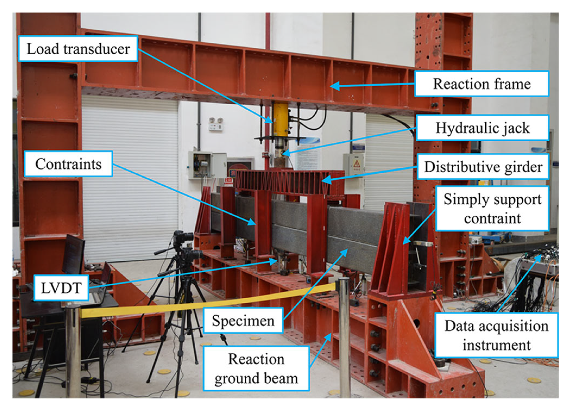
The four-point bending tests were conducted on the full-scale laminated channel beams with only friction interaction and added bolt connections, respectively. The setup for the flexural tests of laminated double beams in modular steel buildings is illustrated in Figure 3. A reaction frame and reaction ground beam were installed to provide a reaction force and fixed constraints during testing. Two simply supported bearing devices were positioned at both ends of the reaction ground beam to supply simple supports and out-of-plane constraints for the beam specimens. On each side of the beam specimens, three out-of-plane constraint devices were installed to restrict out-of-plane deformation of the laminated double beam specimens, thereby simulating the out-of-plane and torsional restraints provided by secondary beams, floor slabs, and ceiling slabs in modular steel buildings. A 100-ton hydraulic jack was mounted at the lower flange at mid-span of the reaction frame beam to apply vertical loading in increments of 10 kN. To perform four-point bending tests on the beam specimens, a load distribution beam was installed on the upper part of the specimen, with its support simply resting on the upper flange of the beam specimen at the quarter-span points. A pressure sensor was arranged between the loading point on the upper flange of the distribution beam and the end of the hydraulic jack to measure the vertical load during the test. Additionally, a rod-type displacement transducer with a range of 100 mm was installed at the lower flange at mid-span of the beam specimen to monitor deflection during the flexural loading process.

5.2. Flexural Performance of Modular Laminated Beam Specimens

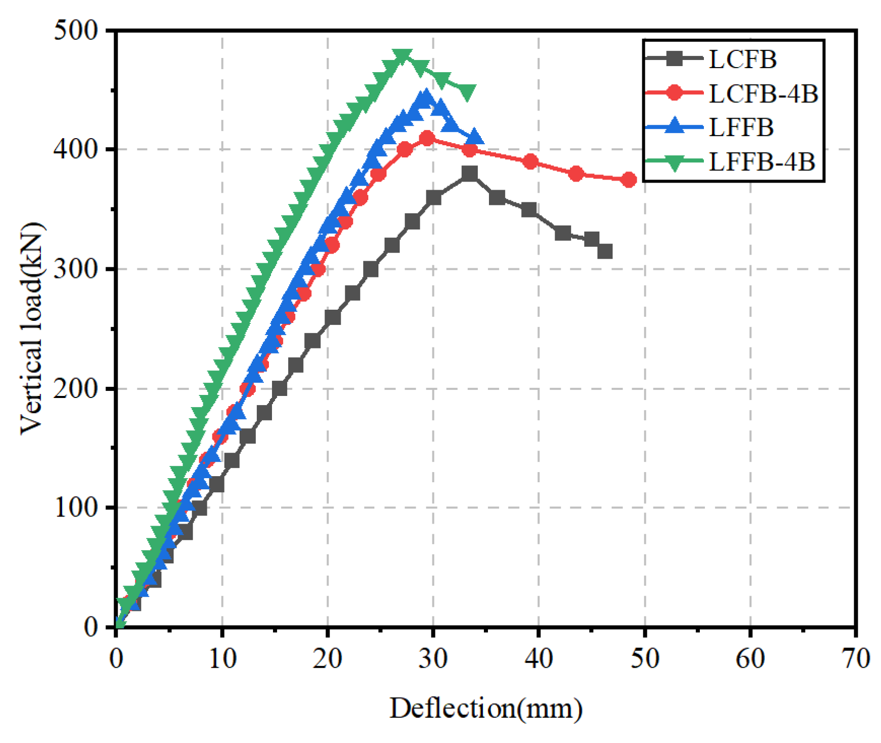
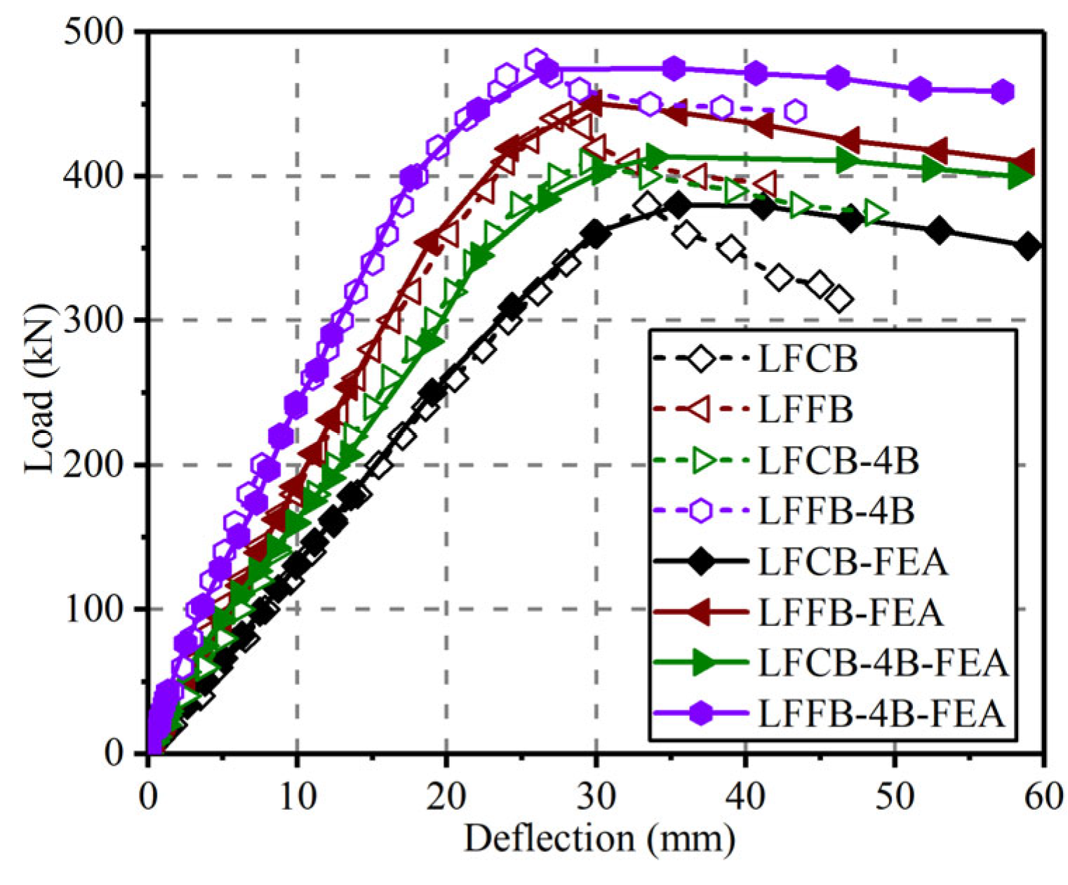
Under the vertical loading, the symmetric flexural deformations about the mid-span section were produced for the laminated beam specimens. By comparatively analyzing the vertical load–deflection curves of the beam specimens, the synergistic effect of the floor beam and the ceiling beam was investigated. As shown in Figure 4, the load–deflection curves of the modular laminated steel beams indicated that the vertical forces were directly transferred to upper and lower beams through normal contact interaction at the interfaces. In specimens LFCB and LFFB, the tangential connection stiffness between the single layers was provided only by the interfacial friction, enabling the coordinated flexural deformations. In specimens LFCB-4B and LFFB-4B, the high-strength bolted connections effectively enhanced the interfacial shear-slipping stiffness, which further improved the overall flexural integrity of the double-beam structures and resulted in significant increases in both ultimate load-bearing capacities and initial bending stiffness.
Aiming to quantify the cooperative behaviors of the double beam structures with bolted connections, a detailed comparison was conducted on the ultimate load-bearing capacity, initial bending stiffness, and secant stiffness at the ultimate load state for the modular laminated beam specimens. As shown in Table 2, the ultimate load-bearing capacity, initial flexural stiffness, and secant stiffness at the ultimate load state for laminated beam specimens with pure friction (LFCB, LFFB) and bolted connections (LFCB-4B, LFFB-4B) were listed, respectively. It was revealed that the ultimate vertical load of the bolted laminated steel beam specimen LFCB-4B increased by 7.89% compared to the pure friction laminated steel beam LFCB, the initial flexural stiffness increased by 27.4%, and the secant stiffness at the ultimate load state increased by 21.9%. For the bolted laminated steel beam specimen LFFB-4B, in which both the upper and lower beams are FB, the ultimate load increased by 8.35%, the initial bending stiffness increased by 27.4%, and the secant stiffness at the ultimate capacity state increased by 16.3% compared to the laminated steel beam specimen LFFB. Compared with the laminated steel beams with only interfacial friction, the interfacial bolted connections further enhanced the shear stiffness at the interface, thereby strengthening the overall flexural integrity of the laminated steel beam specimens LFCB-4B and LFFB-4B. Considering the superimposition effect of laminated beams with increased ceiling beam height, the flexural capacity of LFFB was significantly higher than that of LFCB. The load-bearing capacity, initial flexural stiffness, and secant stiffness of LFFB are 16%, 56%, and 39% higher than those of LFCB, respectively. Similarly, for bolted connections, the load-bearing capacity, initial flexural stiffness, and secant stiffness of LFFB-4B are 17%, 56%, and 33% higher than those of LFCB-4B, respectively. It was found that the bending capacity of bolt-laminated steel beams improved by more than 8% compared to that of specimens with only friction restraints. In addition, the enhancement of bending stiffness exceeded more than 17%. While the percentage gains seemed modest, their implications for engineering design were substantial. An 8% increase in load capacity could translate into a significant reduction in material usage or an extension of the service life of a component. Similarly, a 28% increase in stiffness could critically improve the dimensional stability and precision of a structure. In addition, the improvement of bending stiffness was more pronounced than in capacity. This was due to the fact that the control section kept elastic at the yielding state of components. The structural nonlinear deformations occurred and led to the failure of modular laminated beam specimens. As a result, the material mechanical properties were not fully developed and the structural design mainly depended on the deflection limit but not ultimate capacity. Hence, the promotion of bending stiffness was more obvious than strength for the laminated beam in modular steel buildings.
A comparative analysis of the flexural performance between pure friction laminated steel beams and bolted laminated steel beams indicated that the mutual connection between the layered beams has a significant enhancement on the overall flexural mechanical performance of laminated steel beams. Compared with pure friction laminated beams, the bolted connections effectively increase the shear stiffness at the interface, resulting in a further improvement in the vertical load-bearing capacity of bolted laminated steel beams. The bending stiffness was a critical parameter for in-plane flexural performance analysis and structural design of laminated steel beams. It was indicated that the stiffness enhancement was even more pronounced than the improvement in vertical load-bearing capacity. Compared to frictional contact at the interface, the high-strength bolted connections greatly enhanced the interfacial shear stiffness, making the composite effect between the floor beam and the ceiling beam more prominent. As a result, both the initial flexural stiffness and secant stiffness at the ultimate load state for bolted laminated steel beams were further increased relative to pure friction laminated beams. With the increase in tangential connection stiffness—through either interlayer friction or high-strength bolts—the initial flexural stiffness of laminated steel beam specimens increased accordingly. However, once the interfacial shear connection stiffness reached a certain level, further enhancement in the secant stiffness at the ultimate load state did not continue to increase. Overall, laminated steel beams subjected to vertical loads developed the normal contact and tangential shear connections at the interface, which resulted in the coordinated flexural deformation of the upper and lower beams. The structural integrity of the double beams was effectively improved; thus, the laminated steel beams exhibited superior flexural performance compared to independent double beams.

6. Finite Element Modeling and Parametric Analysis of Laminated Beams in Modular Steel Buildings

6.1. Finite Element Modeling of Laminated Beam Specimens

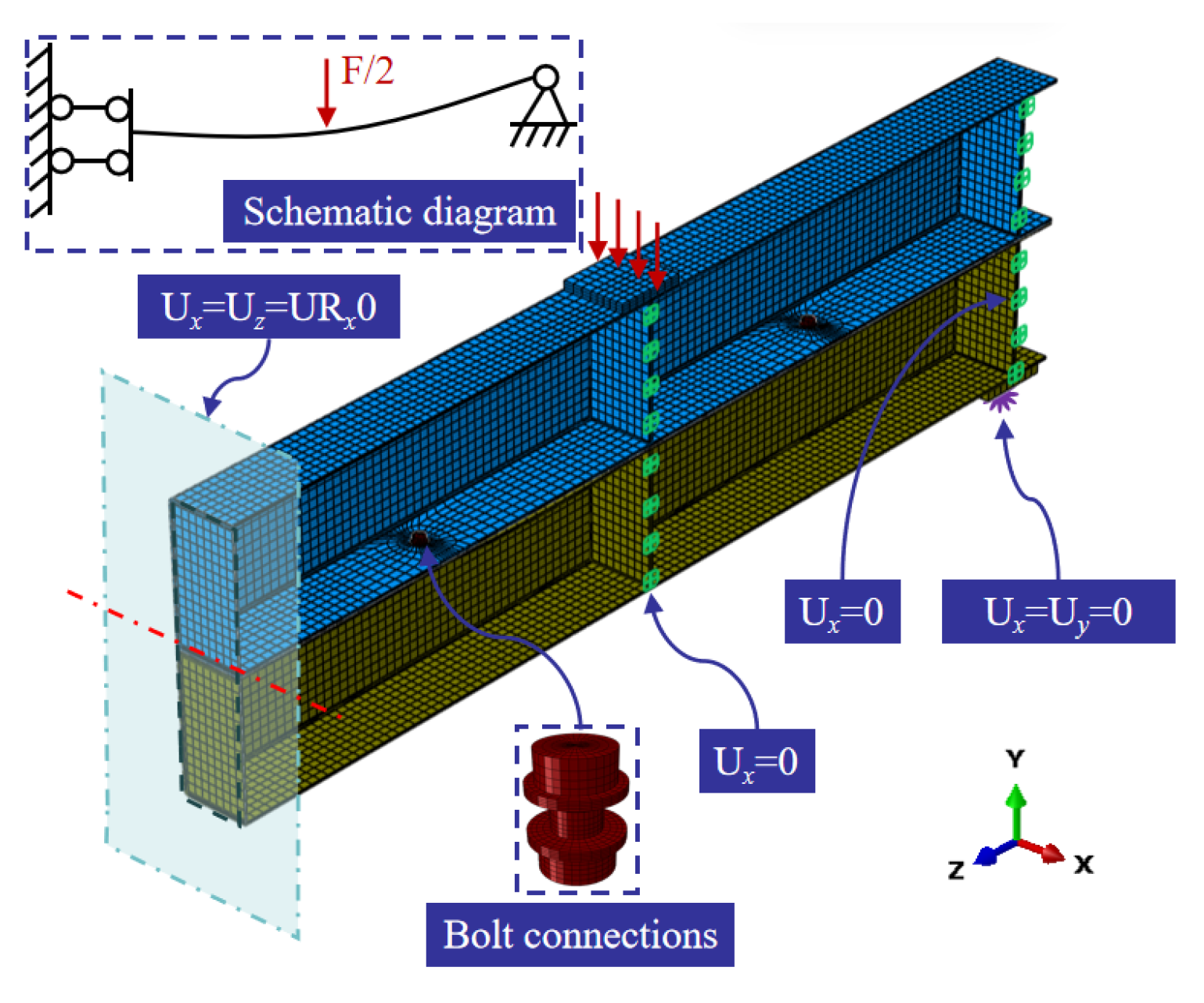
Finite element analysis was conducted to numerically investigate the structural performance and evaluate the influence of key design parameters. A high-fidelity model was developed where the geometric dimensions and loading positions were completely consistent with the experimental specifications. The modeling procedure followed a systematic approach to accurately capture the structural behavior while maintaining computational efficiency. Half of the full model was adopted to exploit structural symmetry, as shown in Figure 5, thereby reducing computational cost. Moreover, the corresponding symmetric boundary conditions were applied along the symmetry plane. The structural material was assumed to be linear elastic and isotropic, with key parameters determined by coupon tests [23]. The boundary conditions were carefully prescribed to represent the physical restraints present in the actual structural system. Specific kinematic constraints were applied at the supports and interconnection regions, with translations (Ux, Uy, Uz) and rotations (UR) restrained in accordance with the schematic illustration, thereby replicating the intended structural connectivity and restraint conditions. The C3D8R solid elements were employed for discretization, and a mesh sensitivity analysis was conducted to determine an optimal element size ensuring both accuracy and efficiency, with local mesh refinement implemented in critical regions such as bolt connections. The loading protocol employed the displacement-controlled actuation, wherein a prescribed displacement was applied, which enhanced the numerical simulation stability through potential stiffness degradation and post-peak behavior, thereby facilitating the tracing of the complete load–displacement path. In this way, this modeling approach could ensure the numerical representation reliably reflects the actual structural stiffness, strength, and load-response characteristics, forming a robust basis for subsequent parametric studies.

6.2. Validation of Finite Element Models

A comparison was performed between the finite element analysis (FEA) and experimental load–deflection curves, which demonstrated a high degree of consistency, thereby validating the reliability of the developed numerical model. As illustrated in Figure 6, the FEA predictions closely aligned with the experimental data for all specimens in terms of initial stiffness and peak load capacity. Although minor deviations were observed in certain deformation stages, which may be attributed to simplifications in material constitutive modeling or idealized boundary conditions, the remarkable agreement in both elastic and post-yield behavior confirmed that the finite element model accurately captured the essential mechanical characteristics and failure mechanisms of the structural members. Consequently, the validated model was deemed suitable for subsequent numerical investigations and parametric analyses of laminated beams in modular steel buildings.

6.3. Parametric Study of Laminated Beam

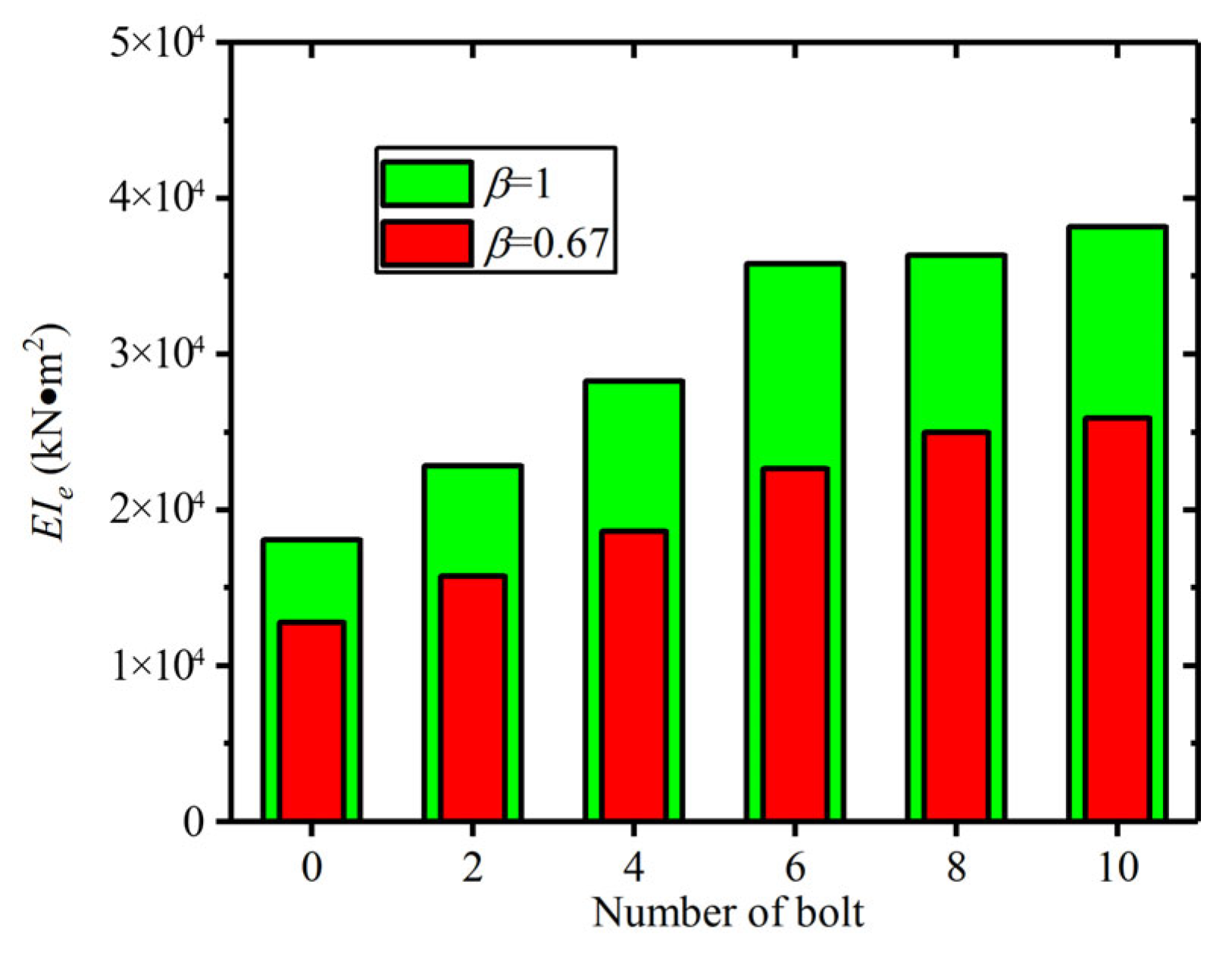
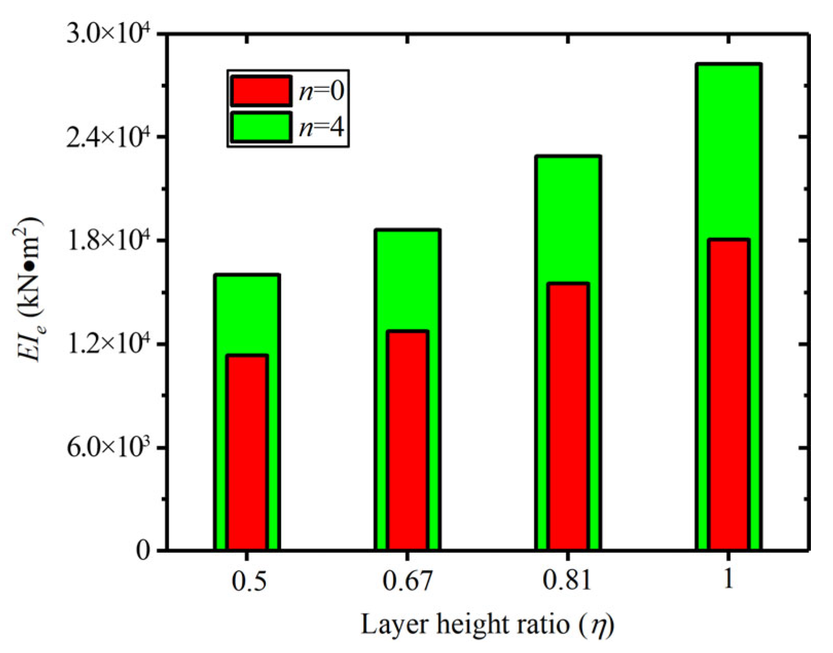
The parametric study was systematically conducted based on the validated finite element models to investigate the influence of bolt connection number and layer height ratio on the structural performance of the laminated beams. In the parametric setup, the number of bolts was varied from 2 to 10, while the layer height ratio (β) was assigned values of 0.67 and 1. These parameters were selected to represent common design scenarios and to evaluate their effects on key mechanical responses, especially for the initial bending stiffness.

6.3.1. Influence of Bolt Number (n)

The analysis revealed a significant and non-linear relationship between the number of bolts and the initial bending stiffness, as shown in Figure 7. It was observed that a rapid increase in bending stiffness as the number of bolts rose from 2 to approximately 6. However, beyond this point, the marginal gain in capacity diminished considerably, indicating a saturation effect. This trend was consistently observed for both layer height ratios (β = 1 and β = 0.67), although the absolute capacity was systematically lower for the smaller ratio. The initial sharp increase was attributed to the enhanced redundancy and more uniform distribution of the load among a greater number of fasteners, which effectively reduced stress concentrations at individual bolt holes. The subsequent saturation was primarily due to the evolution of the force transfer mechanism. As the number of bolts increased, the connection behavior shifted from being bolt-dominated to being governed by the bearing capacity and deformation compatibility of the connected plates themselves. Consequently, simply adding more bolts beyond a certain threshold yielded limited structural benefit. From a design perspective, it was recommended to optimize the number of bolts within the range of 4 to 6, where the most efficient trade-off between performance and cost was achieved for this specific configuration.

6.3.2. Influence of Layer Height Ratio (η)

The influence of the layer height ratio (β) was found to be profound and non-monotonic. The results demonstrated that the structural capacity did not vary linearly with β; instead, an optimum performance was identified at an intermediate ratio of β = 0.67, where the peak capacity was attained. Both a lower ratio (β = 0.5) and a higher ratio (β = 0.81) resulted in a notable reduction in bending stiffness. This optimal phenomenon was explained by the interplay between bending and shear deformations in the connected layers. At the optimal β = 0.67, the stiffness distribution between the layers was balanced, facilitating a more uniform transfer of shear forces and minimizing unfavorable prying actions or localized bending moments. When β deviated from this optimum, an imbalance in stiffness occurred. A lower β (a thinner top layer relative to the bottom) likely led to excessive deformation and stress concentration in the thinner component, while a higher β (more similar layer heights) potentially induced a coupled bending-shear failure mode that compromised the joint efficiency. Therefore, in design practice, it is crucial to carefully calibrate the layer height ratio rather than assuming equal thicknesses. Selecting a ratio in the vicinity of 0.6 to 0.7 was recommended to leverage this synergistic effect and maximize the connection’s structural capacity (Figure 8).

7. Validation of Theoretical Results by Experimental and Numerical Data

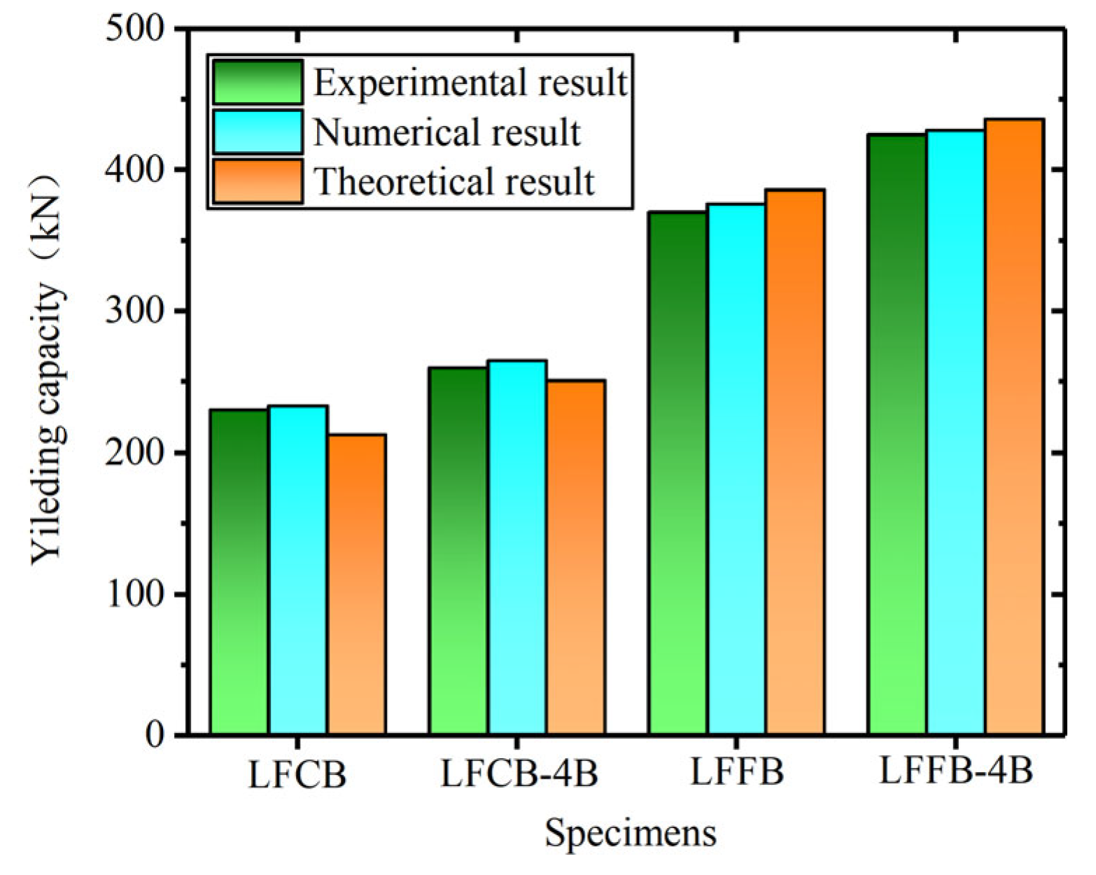
To verify the reliability of the theoretical deflection curve models for the modular laminated steel beams, the analytical results were compared with the experimental and numerical data, as shown in Figure 9. The comparison indicated that, for laminated beams with different interfacial connections, the theoretical values of the yielding loads are in good agreement with the experimental and numerical predictions. The errors for the laminated steel beams generally remained within 8%. Overall, the analytical deflection curve model for laminated steel beams demonstrated the satisfied reliability. The analytical models quantitatively described the cooperative effect of the floor beam and ceiling beams and reasonably calculated the overall mechanical performance of modular laminated beams, providing a reliable theoretical foundation for the design of laminated steel beams in modular steel buildings.

8. Conclusions

In this study, the mechanical properties of modular laminated steel beams were thoroughly theoretically evaluated. The deflection curves were analytically predicted for the laminated steel beams with different configurations, demonstrating the excellent agreement with the experimental data. This validation underscores the feasibility and structural integrity of using laminated steel beams in modular construction, offering practical insights for future engineering applications. The conclusions were summarized as follows:
  • Compared with pure friction laminated double beams, bolted laminated double beams in modular steel buildings exhibit significantly improved flexural performance, with load-bearing capacity increased by approximately 8% and initial flexural stiffness increased by 17% to 28%.
  • Based on the fundamental differential equation of the typical double-beam segment, the analytical expressions for interfacial slipping strain were established. Then, the theoretical models of interfacial slippage were developed for the modular laminated steel beams with different connections.
  • By applying the boundary conditions of simply supported beams, the mathematical expressions were derived for the curvature of modular laminated beams, considering the relative slipping behaviors. In this way, the accurate analytical solutions for deflection and rotation were ultimately obtained.
  • More importantly, the initial bending stiffness of laminated beams was theoretically calculated and validated by experimental results, which effectively quantitatively characterized the collaborative bending effect of double beam structures and significantly provided the dependable theoretical basis for the practical design of modular steel buildings.

Author Contributions

R.L.: conceptualization, data curation, writing—original draft. Y.L.: methodology, data curation, writing—original draft. L.L.: formal analysis, investigation, writing—review and editing. Y.Z.: software, investigation, formal analysis. H.C.: investigation, methodology. Q.Y.: validation, resources. Z.D.: writing—review and editing, validation. B.X.: funding acquisition, supervision. All authors have read and agreed to the published version of the manuscript.

Funding

This research was funded by National Natural Science Foundation of China [Grant no. 52208145], the Project funded by China Postdoctoral Science Foundation [Grant no. 2023M741510], the Project funded by Changzhou Applied Basic Research Program [Grant no. CJ20230032], and Xuzhou Science and Technology Innovation Key R&D Program (Social Development) [Grant no. KC23325].

Data Availability Statement

The original contributions presented in this study are included in the article. Further inquiries can be directed to the corresponding authors.

Conflicts of Interest

Authors Rui Liu, Yong Liu, Li Lin and Yuchao Zheng were employed by the company Shandong Electric Power Engineering Consulting Institute Corp., Ltd. The remaining authors declare that the research was conducted in the absence of any commercial or financial relationships that could be construed as a potential conflict of interest.

References

  1. Pasquire, C.L.; Gibb, A.G.F. Considerations for assessing the benefits of standardisation and pre-assembly in construction. J. Financ. Manag. Prop. Constr. 2002, 7, 1–22. [Google Scholar]
  2. Chen, Z.; Liu, J.; Yu, Y. Experimental study on interior connections in modular steel buildings. Eng. Struct. 2017, 147, 625–638. [Google Scholar] [CrossRef]
  3. Chen, Z.; Wang, J.; Liu, J.; Khan, K. Seismic behavior and moment transfer capacity of an innovative self-locking inter-module connection for modular steel building. Eng. Struct. 2021, 245, 112978. [Google Scholar] [CrossRef]
  4. Corfar, D.-A.; Tsavdaridis, K.D. Tsavdaridis, A comprehensive review and classification of inter-module connections for hot-rolled steel modular building systems. J. Build. Eng. 2022, 50, 104006. [Google Scholar] [CrossRef]
  5. Deng, E.-F.; Du, Y.-P.; Gao, J.-D.; Zhang, Z.; Wang, Y.-B. Seismic performance of an innovative self-centering and repairable connection with SMA bolts in modular steel construction. Thin-Wall Struct. 2024, 205, 112377. [Google Scholar] [CrossRef]
  6. Khan, K.; Chen, Z.; Liu, J.; Tsavdaridis, K.D. Compressive behaviors of corner-supported modular steel sway frames with rotary inter-modular connections. Thin-Wall Struct. 2023, 193, 111245. [Google Scholar] [CrossRef]
  7. Lacey, A.W.; Chen, W.; Hao, H.; Bi, K. Structural response of modular buildings—An overview. J. Build. Eng. 2018, 16, 45–56. [Google Scholar] [CrossRef]
  8. Lacey, A.W.; Chen, W.; Hao, H.; Bi, K. Review of bolted inter-module connections in modular steel buildings. J. Build. Eng. 2019, 23, 207–219. [Google Scholar] [CrossRef]
  9. Lawson, R.M.; Ogden, R.G.; Bergin, R. Application of modular construction in high-rise buildings. J. Archit. Eng. 2001, 118, 148–154. [Google Scholar] [CrossRef]
  10. Khan, K.; Chen, Z.; Liu, J.; Tsavdaridis, K.D. Tsavdaridis, Experimental and analytical investigations on compression behaviors of rotary-connected sway column-supported steel modular interior frames. J. Build. Eng. 2023, 78, 107692. [Google Scholar] [CrossRef]
  11. Lacey, A.W.; Chen, W.; Hao, H.; Bi, K. New interlocking inter-module connection for modular steel buildings: Experimental and numerical studies. Eng. Struct. 2019, 198, 109465. [Google Scholar] [CrossRef]
  12. Lacey, A.W.; Chen, W.; Hao, H.; Bi, K. Lateral behaviour of modular steel building with simplified models of new inter-module connections. Eng. Struct. 2021, 236, 112103. [Google Scholar] [CrossRef]
  13. Lacey, A.W.; Chen, W.; Hao, H.; Bi, K. New interlocking inter-module connection for modular steel buildings: Simplified structural behaviours. Eng. Struct. 2021, 227, 111409. [Google Scholar] [CrossRef]
  14. Mostafaei, H.; Barmchi, M.A.; Bahmani, H. Bahmani, Seismic Resilience and Sustainability: A Comparative Analysis of Steel and Reinforced Structures. Buildings 2025, 15, 1613. [Google Scholar] [CrossRef]
  15. Li, J.; Deng, L.; Sang, D.; Wang, D. Experimental research on flexural behaviour of laminated steel beams. Ind. Constr. 2015, 45, 115–118+45. [Google Scholar]
  16. Li, J.; Sang, D.; Wang, D.; Li, L. Experimental Research on Laminated Steel Beamswith Non-continuous Connectors. Struct. Eng. 2013, 29, 125–131. [Google Scholar]
  17. Chang, H.; Hu, L.; Song, X.; Qin, F.; An, A.; Zhang, S. Experimental test and parametric analysis on flexural performance of laminated square tubular beams in steel box module. J. China Univ. Min. Technol. 2022, 52, 540–549. [Google Scholar]
  18. Zhang, A.; Liu, J.; Chen, Z.; Chen, T. Bending behavior of detachable tapered-head bolt inter-module connection of steel modular structure. J. Constr. Steel Res. 2024, 220, 108829. [Google Scholar] [CrossRef]
  19. Zhang, A.L.; Guo, Z.P.; Liu, X.C.; Li, C. Global stability coefficient of prefabricated beams with dual-channel combined section. Eng. Mech. 2018, 35, 67–75. [Google Scholar]
  20. Zha, X.; Zhai, X.; Wang, Q. Mechanical properties of assembled frame connected bydouble-beam and double-column angle jointswithout on site welding. J. Build. Struct. 2018, 39, 8–15. [Google Scholar]
  21. Zhai, X.M.; Xiong, C.X.; Gan, Y.L. Experimental study and numerical simulation on assembled frame with double-beam multi-column joints. J. Harbin Inst. Technol. 2020, 52, 81–87. [Google Scholar]
  22. Zhu, Y.; Zhao, J. Experimental and numerical study on member classification of I-section plate girders. J. Constr. Steel Res. 2017, 137, 192–200. [Google Scholar] [CrossRef]
  23. Xu, B.; Xia, J.; Chang, H.; Ma, R.; Zhang, L. A comprehensive experimental-numerical investigation on the bending response of laminated double channel beams in modular buildings. Eng. Struct. 2019, 200, 109737. [Google Scholar] [CrossRef]
  24. Xu, B.; Xia, J.; Chang, H.; Ma, R.; Zhang, L. Flexural behaviour of pairs of laminated unequal channel beams with different interfacial connections in corner-supported modular steel buildings. Thin-Wall Struct. 2020, 154, 106792. [Google Scholar] [CrossRef]
  25. Xu, B.; Xia, J.; Chang, H.; Ma, R.; Zhang, L. Evaluation of superimposed bending behaviour of laminated channel beams in modular steel buildings subjected to lateral load. Thin-Wall Struct. 2022, 175, 109234. [Google Scholar] [CrossRef]
  26. Xu, B.; Xia, J.; Chang, H.; Ma, R.; Zhang, L. Experimental and numerical investigation on the lateral force resistance of modular steel sub-frames with laminated double beam. J. Build. Eng. 2022, 46, 103666. [Google Scholar] [CrossRef] [PubMed]
  27. Xu, B.; Xia, J.; Ma, R.; Chang, H.; Yang, C.; Zhang, L. Investigation on interfacial slipping response of laminated channel beams with bolt connections in modular steel buildings. J. Build. Eng. 2023, 63, 105441. [Google Scholar] [CrossRef]
  28. Handbook for the Design of Modular Structures; CRC Press: Boca Raton, FL, USA, 2017.
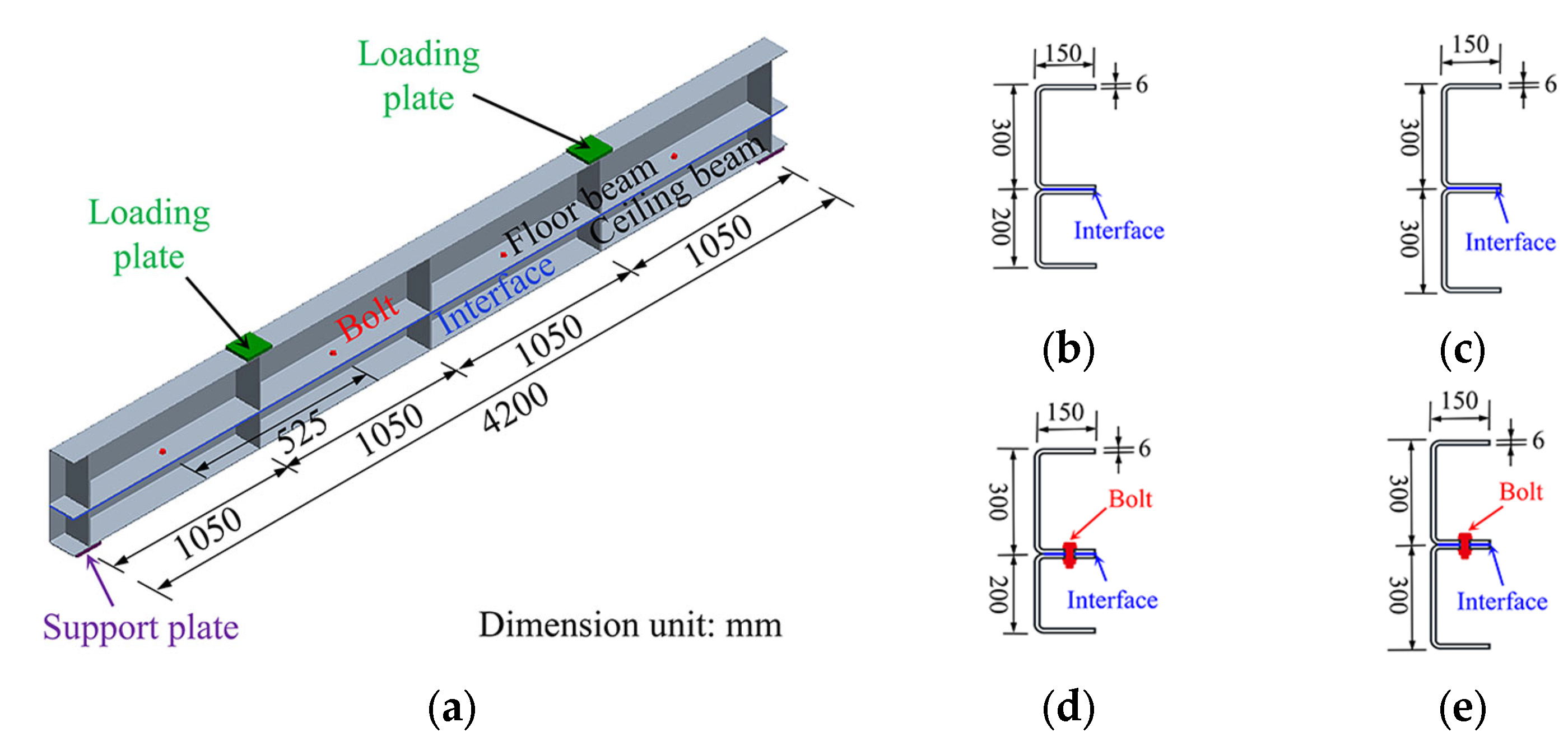
Figure 1. Geometries and dimensions of laminated beam specimens: (a) geometric detail; (b) LFCB; (c) LFFB; (d) LFCB-4B; (e) LFFB-4B.
Buildings 15 04221 g001
Figure 2. Strain distribution of laminated beam.
Buildings 15 04221 g002
Figure 3. Set-up of bending test.
Buildings 15 04221 g003
Figure 4. Vertical load–deflection curves.
Buildings 15 04221 g004
Figure 5. Symmetric semi-finite element model with geometry, mesh and boundary conditions.
Buildings 15 04221 g005
Figure 6. Comparison of numerical and experimental results [23,24].
Buildings 15 04221 g006
Figure 7. Influence of bolt number.
Buildings 15 04221 g007
Figure 8. Influence of layer height ratio.
Buildings 15 04221 g008
Figure 9. Comparison of calculated model by test and simulation results.
Buildings 15 04221 g009
Table 1. Dimensions of beam specimens (mm).
SpecimenFloor Beam
hu × w × tb
Ceiling Beam
hu × w × tb
lcl0li
LFCB300 × 150 × 6200 × 150 × 615504200500
LFFB300 × 150 × 6300 × 150 × 615504200600
LFCB-4B300 × 150 × 6200 × 150 × 615504200500
LFFB-4B300 × 150 × 6300 × 150 × 615504200600
Note: (1) hu denotes beam height; (2) w denotes beam width; (3) tb denotes web thickness; (4) lc denotes stiffener spacing; (5) l0 denotes the total beam length; (6) li denotes the beam section height.
Table 2. Flexural performance of double beams under vertical load.
Fexp
(kN)
Dfal
(mm)
Sini
(kN·m)
Ksec
(kN/m)
HcapHinsHses
LFCB38033.421.35 × 1061.14 × 103
LFFB44327.812.11 × 1061.59 × 103
LFCB-4B41029.431.72 × 1061.39 × 1037.89%27.4%21.9%
LFFB-4B48025.992.69 × 1061.85 × 1038.35%27.4%16.3%
Note: (1) Fexp denotes the experimental vertical failure load; (2) Dfal denotes the mid-span deflection at the failure load; (3) Sini denotes the initial flexural stiffness; (4) Ksec denotes the secant stiffness at the failure load; (5) Hcap denotes the increase in load-bearing capacity; (6) Hins denotes the increase in initial flexural stiffness; (7) Hses denotes the increase in secant stiffness.
Disclaimer/Publisher’s Note: The statements, opinions and data contained in all publications are solely those of the individual author(s) and contributor(s) and not of MDPI and/or the editor(s). MDPI and/or the editor(s) disclaim responsibility for any injury to people or property resulting from any ideas, methods, instructions or products referred to in the content.