Abstract
This study investigates an alternative methodology for incorporating polymeric and steel fibers into concrete. Conventional reinforcement approaches often require complex application techniques and face industrial limitations. In contrast, the present work evaluates the use of short, discontinuous fibers—commercial polypropylene fibers (PFRC), polypropylene fiber braid (PFBRC) and steel fibers (SFRC)—which enable improved dispersion, ease of mixing and potential mechanical benefits. The fibers were randomly oriented and evenly distributed within the cementitious matrix. Mechanical performance was assessed through four-point bending tests combined with displacement measurements, acoustic emission analysis and uniaxial compression tests, while scanning electron microscopy (SEM) confirmed fiber–matrix interaction and fragment retention. The results demonstrated significant improvements, with compressive strength exceeding that of unreinforced concrete, while hybrid fiber systems provided enhanced crack resistance and post-cracking stability. Overall, the findings highlight that the integration of discontinuous fibers may provide tangible mechanical advantages, potentially outweighing the structural benefits of continuous reinforcing bars in applications requiring high strength and reliable mechanical performance.
1. Introduction
Concrete is the most widely used construction material worldwide, yet its inherent brittleness and susceptibility to cracking limit its long-term performance and structural reliability. To address these limitations, numerous studies have explored the incorporation of fibers into cementitious matrices as a means of enhancing strength, ductility and crack resistance [1,2,3]. Polymeric fibers have attracted considerable attention due to their low cost, chemical stability and ability to mitigate shrinkage cracking and improve energy absorption [4,5,6]. Similarly, steel fibers have been shown to provide significant improvements in compressive strength, toughness and post-cracking resistance [7,8,9]. Recent advances in fiber-reinforced concrete (FRC) have demonstrated that the combination of different fiber types can generate a synergistic effect, resulting in composites with enhanced mechanical performance compared to those reinforced with a single fiber type [10,11,12]. Such hybrid fiber-reinforced concretes (HyFRCs) are of particular interest for applications requiring a balance of compressive strength, tensile resistance and fracture toughness. Furthermore, developments in fiber geometry, aspect ratio and dosage have been shown to influence fiber–matrix interaction, directly affecting the load transfer and crack-bridging efficiency of the composite [13,14,15]. Despite the growing body of research, several knowledge gaps remain. In particular, the majority of previous studies have focused on either steel or polymeric fibers individually, while fewer works have systematically examined their combined effect in a controlled cementitious matrix. Moreover, the performance of hybrid fiber systems under simultaneous evaluation of compressive strength, flexural behavior and acoustic emission monitoring has not been extensively reported. The present study examines the incorporation of commercial polypropylene fibers (PFRC), polypropylene fiber braid (PFBRC) and steel fibers (SFRC) into concrete matrices. The fibers were introduced in a randomly oriented and evenly dispersed manner to assess their impact on the mechanical performance of the composite. A systematic experimental study was implemented comprising uniaxial compression tests, four-point bending tests with displacement monitoring and acoustic emission analysis. In addition, scanning electron microscopy (SEM) was employed to investigate fiber–matrix interactions and evaluate the microstructural integrity of the material. By integrating these methods, the study aims to provide new insights into the role of hybrid fiber systems in enhancing the mechanical reliability of concrete, thereby contributing to the development of next-generation fiber-reinforced composites for structural applications.
2. Materials and Methods
2.1. Fibers Characteristics
Three different sizes of polypropylene fibers and one type of steel fiber were used as reinforcement: polypropylene fiber braid (PFBRC), standard commercial PP fibers (PFRC) and steel fibers (SFRC) (Figure 1). The first two types were incorporated at a percentage of 0.9% w/w and the third at 8.3% w/w. These fiber dosages were not chosen arbitrarily, but were based on standard ranges reported in the literature for fiber-reinforced mortars and concretes aiming to enhance crack resistance, toughness and elastic behavior. Specifically, polypropylene fiber contents of approximately 0.9% by weight and steel fiber volumes around 1.0% (equivalent to ~8.3% by weight) are widely used and have been shown to improve mechanical properties without compromising workability [11,13]. The polypropylene fiber braid and commercial polypropylene fibers were supplied by DOMYLCO CONSTRUCTION CHEMICALS Ltd. (Acharnes, Attica, Greece). The characteristics of the fibers are presented in Table 1. Although the lengths of the fibers used in the fiber-reinforced concrete varied, the ratio of polymer fibers was kept constant, as recommended by the manufacturer for both polymer and steel fibers. This study, however, aims to compare the different types of fibers while maintaining the current ratio specified by each manufacturer. The ratios of fibers were kept constant in order to isolate and evaluate the effect of fiber type and geometry on the mechanical performance, without the added variability of changing fiber volume fractions. It should be clarified that these percentages are expressed as fiber-to-cement ratios, not fiber-to-total mixture mass. When calculated relative to the total concrete mass, the actual dosages correspond to approximately 0.09% (PP fibers) and 0.83% (steel fibers), consistent with Table 2 values.
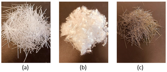
Figure 1.
Fiber types used in the present study: (a) polypropylene fiber braid, (b) polypropylene commercial fibers, and (c) steel fibers.

Table 1.
Characteristics of the fibers used.

Table 2.
Concrete mix design.
2.2. Proportions of the Materials in the Concrete Mix Design
The concrete mix design was determined in accordance with ACI 211.2 [16] under a volumetric method to achieve a target characteristic compressive strength (fck) of 28 days as 30 MPa, which is the same as the standard target strength. The aggregates used in the study correspond to typical limestone, well-graded sand (maximum grain size 4.75 mm), fine and coarse gravel (maximum grain size of 12.5 and 25.0 mm, respectively) and the design slump was 75 to 90 mm (Class S2 according to EN 12350-2:2009 [17]) (Figure 2). Specimen casting was performed under laboratory conditions with CEM II/A-P to produce strength class C30/37 concrete. The water-to-cement ratio (W/C) was fixed at 0.54 for all batches in the conducted experiments. The sole variable of the mixtures was the inclusion of steel and polypropylene fibers with different fiber lengths and diameters. Curing was provided for 28 days under normal ambient conditions using potable water in designated plastic curing tanks in order for the specimens to reach their full strength (Figure 2). The reference sample (plain specimen) and their fiber-reinforced counterparts (PFRC/SFRC specimen, PFBRC/SFRC specimen, PFRC/PFBRC specimen, PFRC/PFBRC/SFRC specimen) were provided with the same curing treatment. A follow-up experimental program with hybrid fiber reinforcement was performed to ascertain the synergistic advantages of incorporating steel and polypropylene fibers, together, to further enhance the mechanical performance and characteristics beyond the achievable levels for each type of fibers [14]. Table 2 presents the detailed proportions of each constituent, including the admixture Visco 6000, which functions as a high-range water-reducing plasticizer to improve workability. It is noted that, in standard mix design, aggregate content should typically be reduced with increasing fiber content to maintain consistent workability and volume balance; however, in this study, the aggregate mass was kept constant to allow for direct comparison across mixtures.
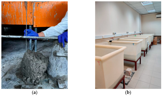
Figure 2.
The dedicated slump test (a) and the designated plastic curing tanks (b).
Subsequent to curing time, all the samples were subjected to a series of routine tests to quantify key performance characteristics like compressive and flexural strengths, acoustic emission behavior and microstructure characteristics via scanning electron microscopy (SEM).
2.3. Four-Point Bending Tests
During the four-point bending test, a universal testing machine, INSTRON 5967, Instron, Norwood, MA, USA, was used, which was equipped with a 30 kN load cell and steel rollers in four-point alignment. The rate of loading was always maintained at 0.08 mm/min. The bending curvature was measured using an exoskeleton frame, which was specially made to have an extensometer for obtaining precise displacement. Sample preparation was conducted in three stages over a period of three days. Samples were removed from the hydration bath within the first 24 h to eliminate free surface water to facilitate safe attachment of a metallic interface piece of the extensometer. On day two, each sample was gently washed and both faces measured to locate the precise central axis, on which the metal piece was bonded with a resin-based adhesive. Once there was another 24 h bonding duration, the exoskeleton mechanism integration was complete and the four-point bending test began.
2.4. Compressive Strength Tests
To determine the maximum compressive strength of the concrete samples, a series of compression tests was carried out. This employed a simple but very robust method of mechanical testing of concrete. The cube-shaped specimens with dimensions 15 × 15 × 15 cm were prepared for this purpose. Minimal preparation was required other than to remove the samples from the curing bath one day prior to testing and record their physical dimensions.
There were three samples measured for each type of specimen to the ensure statistical strength and reproducibility of the results. This test technique is described as being accurate because it is quite close to actual stress conditions, providing critical information on the structural behavior of the material when subjected to load. Compression testing also plays a basic function in the advancement of composite materials technology due to the fact that it allows researchers to optimize mechanical properties before scaling up to industrial quantities.
2.5. Acoustic Emission Tests
In order to observe the evolution of bending tests more effectively, the non-destructive testing method of acoustic emission (AE) was used with the help of two sensors (Figure 3). With this method, internal deformation within the specimen can be monitored in real-time and valuable information about its mechanical behavior, such as microcrack formation, crack propagation, flexural cracking and damage location, can be obtained [18,19]. AE was applied to five different samples: a plain (unreinforced) sample, a sample reinforced with polypropylene fibers and steel fibers (PFRC/SFRC), a sample with polypropylene fibers and a polypropylene fiber braid (PFRC/PFBRC), a sample with steel fibers and a polypropylene fiber yield (SFRC/PFBRC) and a hybrid sample with all three forms of reinforcement (PFRC/PFBRC/SFRC) [15,20].
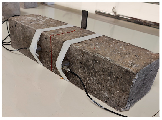
Figure 3.
Specimen with the two acoustic emission sensors.
Two Physical Acoustics Corporation (PAC) AE sensors, that operate at 50–400 kHz and are 10 cm apart, were employed in data acquisition. The sensors were attached to PAC preamplifiers type 2/4/6, which equate to gain levels of 20, 40 and 60 dB, respectively. Signal capture was performed using the AEwin™—Real-time Data Acquisition and Replay Software and the use of honey as a coupling agent was made to achieve the best transfer of acoustic signals from the test specimen to the sensors. The 40 dB threshold was applied in the AEWin system (Physical Acoustics Corporation, MISTRAS DataSolutions, NJ, USA) to filter out the best unwanted background noise and enhance resolution and the reliability of the acquired data. Gradual filtering and proper interpretation of the AE signals are needed as there is a wide variety of acoustic events possible to be recognized from the initial stage of cracking to the reorientation of fibers in the concrete matrix. The principal parameters considered were hits and the AE signal amplitude. On the graphical plots, the flexural load is indicated using a red line, the hit accumulation is in black and the amplitude values are presented as a scatter plot (as seen in Section 3.3—Acoustic Emission) and their interpretation was conducted in accordance with published research [21].
2.6. Scanning Electron Microscopy
The preparation of samples for scanning electron microscopy (SEM) is a meticulous and time-intensive process. It involves isolating a small fragment—typically no larger than 20 μm—to ensure proper placement in the sample holder. The selected section is always obtained from the fracture surface of the specimen to capture the most representative microstructural features [22]. Once isolated, the fragment is examined to confirm the presence of inert components and, if applicable, fibers intended for microscopic analysis.
Following this, the sample is stored in a vial containing silica gel to facilitate initial drying. After several days, it is transferred to a vacuum oven to eliminate any remaining moisture. This drying step is essential to enable the subsequent silver coating process and to ensure that the sample remains stable under vacuum conditions during SEM observation [23,24].
Scanning electron microscopy (SEM) images were obtained using a JEOL JSM 6510-LV SEM Microscope instrument (JEOL Ltd., Tokyo, Japan) equipped with an X-Act EDS-detector from Oxford Instruments for energy dispersive X-ray spectroscopy (Abingdon, Oxfordshire, UK) with an acceleration voltage of 20 kV for elemental analysis and mapping. Prior to analysis, the samples were covered with an Au-Pd thin film (4–8 nm) using the SC7620 mini sputter coater from Quorum Technologies Ltd. (Kent, UK).
Energy dispersive X-ray spectroscopy (abbreviated as EDXS) was used to analyze elemental composition at the fiber–matrix interface. Spot analyses were performed at 15 kV accelerating voltage and spectra were processed using the specific software provided by Oxford Instruments.
3. Results and Discussion
3.1. Macroscopical Observations of Samples
For specimens containing polypropylene fibers, visual observations revealed that upon crack formation, no fragments were produced in the cubic specimens subjected to fracture and no part of the prismatic specimens subjected to four-point bending became detached (Figure 4 and Figure 5). This indicates a significant enhancement in the structural integrity of the material due to the addition of polypropylene fibers. The fibers appear to act as bridges across cracks, distributing stress and preventing complete disintegration under load [25,26]. These improvements suggest potential applications in areas requiring durable and resilient materials, such as earthquake-resistant structures or military installations [27]. Further studies could explore optimal fiber concentrations for various use cases, potentially leading to broader implementation across different engineering fields.
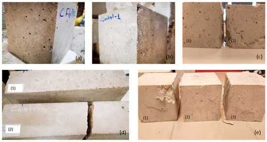
Figure 4.
(a) Polypropylene fiber-reinforced cubic specimen under compression and (b) unreinforced cubic concrete specimen after compression. (c) Comparative results of the two cubic test samples after compression: (1) fiber-reinforced concrete and (2) unreinforced concrete. (d) prismatic specimens after the four-point bending test (1) fiber-reinforced prismatic specimen showing only cracks and (2) unreinforced specimen which was completely detached. (e) Comparative results of concrete samples after compression: (1) unreinforced concrete, (2) polypropylene fiber-reinforced concrete and (3) steel fiber-reinforced concrete.
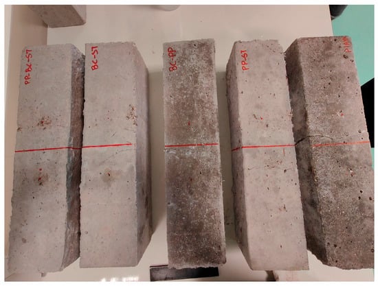
Figure 5.
The five specimens used in the four-point bending tests.
3.2. Four-Point Bending Test
The four-point bending test indicated an unexpected response in the specimens reinforced with steel fibers. While the typical post-cracking bridging effect was not strongly visible, this could be attributed to fiber dispersion, orientation, or insufficient crack opening to activate bridging. Therefore, the observed absence of pronounced post-cracking resistance does not necessarily contradict established fiber-reinforced concrete behavior but suggests the need for further testing.
The four-point bending test was performed by determining the bending elongation deflection, revealing a twofold increase in strength for samples incorporating randomly oriented polypropylene fibers. As shown in Figure 6a, the strength of the unreinforced sample at 10,929 N is shown in black (plain), the strength of commercial polypropylene fibers with a maximum strength of 20,159 N is shown in red (PFRC), while the blue color shows the strength of the polypropylene fiber mesh at 13,989 N (PFBRC) and finally, the green color shows the strength of the steel fibers at 20,704 N (SFRC).
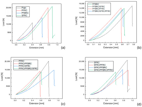
Figure 6.
Four-point bending diagram and comparison of fiber-reinforced specimens (a). Four-point bending diagram and comparison of samples reinforced with different types of fibers based on polypropylene fiber braid (b). Four-point bending diagram and comparison of samples reinforced with different types of fibers based on commercial polypropylene fibers (c). Four-point bending diagram and comparison of samples reinforced with different types of fibers based on linear steel fibers (d).
As shown in Figure 6b, the polypropylene fiber braid caused a relative increase in flexural strength compared to the unreinforced concrete specimen, but this increase cannot be considered significant. The same diagram shows that the fiber-reinforced concrete specimens with polypropylene and steel fibers have similar flexural strength, indicating that the two different reinforcement materials may have similar behavior to the steel reinforcement of conventional reinforced concrete. A combination of fibers was used, mainly the polypropylene fiber braid, from which it appears that only the fiber-reinforced concrete specimen containing the polypropylene fiber braid with the addition of steel fibers showed the greatest increase in strength and elongation. In addition, the polypropylene fiber braid significantly reduced the strength of fiber-reinforced concrete with steel fibers, which can be attributed to the ineffective adhesion between the fibers. The polypropylene fiber mesh is shown in green at 13,976 N (PFBRC), while the combination of steel fibers and polypropylene fiber mesh with a maximum strength of 14,245 N (PFBRC/SFRC) is depicted in black, the combination of polypropylene fiber braid with commercial polypropylene fibers with a maximum strength of 14,115 N (PFBRC/PFRC) is shown in red and finally, the blue color shows the final combination of all fiber types with a maximum strength of 13,736 N (PFBRC/SFRC/PFRC).
Similar behavior is evident from the data shown in Figure 6c, suggesting that the adhesion of the fibers, even in the case of a combination of different fibers with polypropylene fiber as the main fiber, is not satisfactory, as it weakens the existing strength offered by polypropylene fibers when used alone. In Figure 6c, it can be seen that commercial polypropylene fibers without the addition of other types of fibers offer the maximum flexural strength. This is probably due to the adhesion between the fibers. For all possible combinations, a decrease in flexural strength is observed, with maximum strength ranging from 14,000 N to 14,500 N for the PFRC/PFBRC (in red), PFRC/SFRC (in blue) and PFRC/PFBRC/SFRC (in green), while the maximum flexural strength for the PFRC specimen is 20,159 N (in black). The reduction in flexural strength is not necessarily a limiting factor, as the benefits of combining fibers must always be taken into account, which often outweigh the maximum strength. Supporting the concrete on three size scales can provide maximum restraint of the fragments of a failed test. The goal, therefore, is not necessarily to increase the maximum strength, but to maintain it in relation to the existing strength of conventional concrete in combination with the containment of fragments.
Regarding the combination of fibers with steel fiber as the main fiber, as shown in the data in Figure 6d, their behavior is enhanced and this can be attributed to the fact that the steel fiber provides the basic support. This discrepancy in behavior suggests that the matrix interaction between polypropylene fibers and the base material may be more synergistic compared to that of steel fibers, which indicates that the composition of the material and the orientation of the fibers significantly affect the mechanical properties of the composites. We can again observe that the combination of fibers does not offer a particularly large increase in the flexural behavior of the composite cementitious material but increases the elongation as shown by the x-axis determined by the bending arrow. There is still the same correlation between the combinations of different types of fibers, but there is probably still no adhesion between them. In addition, special mention must be made of the elongation of the samples as there is a differentiation in the type of fibers, maximum elongation is observed in samples containing commercial polypropylene fibers due to the elasticity of the fibers themselves, which can increase the plasticity of the composite cementitious material.
The four-point bending test was performed as denoted by a bending–elongation arrow, revealing a twofold increase in strength for samples incorporating polypropylene fibers with random orientations. However, with the introduction of steel fibers with random orientation, no increase in strength was observed. This discrepancy in material performance suggests that the matrix interaction between polypropylene fibers and the base material might be more synergistic compared to that of steel fibers [28,29]. The load–deflection curves obtained from replicate specimens exhibited consistent behavior, indicating reproducibility of the bending test results. The relatively limited post-cracking residual strength compared to other FRC studies is potentially attributable to fiber orientation and dispersion effects rather than measurement artifacts. This behavior underscores the sensitivity of flexural performance to fiber distribution within the matrix.
Further investigation into the microstructural effects caused by different fiber materials could elucidate why such variations occur. Additionally, exploring alternative orientations and distributions of these fibers within the composite may yield insights into optimizing mechanical properties for specific applications. Considering environmental factors (i.e., temperature and humidity), future tests could also reveal important durability characteristics of these composites under varying conditions [13].
3.3. Acoustic Emission
Regarding the plain specimen (Figure 7), there is a steady increase in acoustic emission hits until the specimen reaches its breaking point at approx. 9 kN. According to the amplitude diagram, the initial hits are caused by internal micro-cracks at relatively low dB (40–70 dB) and as the load progresses, there is an increase in dB, as the accumulation of cracks suddenly forms a macroscopic crack, breaking the specimen according to research by [Aggelis 2011] [30].
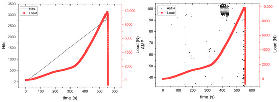
Figure 7.
Acoustic emission diagrams with accumulative AE hits and amplitude for plain specimen.
For the PFRC/SFRC specimen (Figure 8), there is a sudden increase in hits until approx. 4000 hits. Then, as the load increases, there is no increase in hits and this is possibly attributed to the contribution of steel fibers acting as a bridge, limiting crack growth and increasing tensile strength as observed in the research of [Ren et al., 2023] [31]. When the load increases further, there is an increase in hits until the specimen’s breaking point and the same pattern is observed in the amplitude diagram where with the increase in load and hits, there are higher dBs, indicating the formation of cracks based also on the results of [Li et al., 2018, Mpalaskas et al., 2021] [32,33].
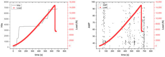
Figure 8.
Acoustic emission diagrams with accumulative AE hits and amplitude for PFRC/SFRC specimen.
As for the PFBRC/SFRC specimen (Figure 9), the polypropylene fiber braids are similar to the steel fibers as far as resisting tensile forces and providing flexural strength, as seen in Figure 6 with the sudden increase in the load range (6–14 kN) until the breaking point of the specimen. According to the amplitude diagram, there are micro-cracks at the start of the experiment, and alongside the hits diagram, there is failure between the components of the specimen such as the aggregates and the fracture of the polypropylene fiber braids, as shown as in research by [Aggelis et al., 2011, Mpalaskas et al., 2024] [34,35].
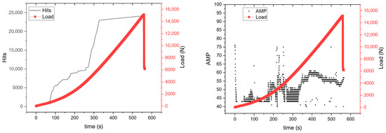
Figure 9.
Acoustic emission diagrams with accumulative AE hits and amplitude for PFBRC/SFRC specimen.
For the PFRC/PFBRC specimen (Figure 10), there is a sudden increase in hits close to the breaking point of the specimen. According, also, to the amplitude diagram, there were events at relatively high dBs (80–90) at the start of the experiment, indicating the breaking of the polypropylene fiber braids without the breakage of the specimen, in accordance with previous research [Tan et al., 2021] [36].
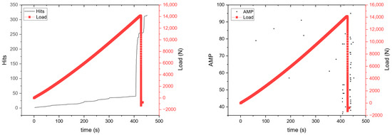
Figure 10.
Acoustic emission diagrams with accumulative AE hits and amplitude for PFRC/PFBRC specimen.
Regarding the PFRC/PFBRC/SFRC specimen (Figure 11), the combination of all three types of reinforcement has provided the specimen with a combination of characteristics such as the steady increase in hits as the load increases ending with a sudden increase in hits before the rupture of the specimen, while the dBs were low, indicating minimum fiber fractures until the rapture of the specimen at increased dBs, as per previous work [Chaturvedi, Singh and Sharma 2021] [37].
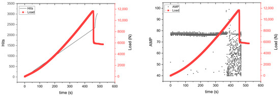
Figure 11.
Acoustic emission diagrams with accumulative AE hits and the amplitude for PFRC/PFBRC/SFRC specimen.
3.4. Compression Tests
The compression tests verified that the concrete samples with polypropylene fibers have no significant impact on compression strength compared to the control concrete samples, as illustrated in Table 3, depicting the compression results for all the specimens tested in accordance with published references [25]. However, when coupled with steel fibers, the concrete composite shows significant increase in compression strength when compared with conventional steel fiber-reinforced concrete [38]. The findings from the compression tests demonstrate the potential of using a combination of polypropylene and steel fibers in concrete, as it results in a substantial increase in compression strength. This not only provides reinforcement but also improves the overall performance of the concrete, suggesting that the synergy between polypropylene and steel fibers in the concrete matrix is responsible for this enhanced performance [39]. There are strong indications that while polypropylene fibers alone do not contribute significantly to compressive strength, their role in a hybrid fiber system could be more about improving other mechanical properties, like ductility or cracking resistance [40]. Future research is required on quantifying how these two types of fibers interact at different ratios and under various loading conditions to optimize concrete formulations for specific structural applications [41].

Table 3.
Compression tests for different fiber-reinforced specimens.
3.5. Scanning Electron Microscope (SEM)
Microscopy indicates the random orientation of fibers within the concrete matrix, encompassing the average dimensions and distribution of both polypropylene and steel fibers. These observations are crucial for understanding the influence of fiber geometry and dispersion on the mechanical performance of the composite material. Ongoing verification efforts, utilizing advanced characterization techniques, also focus on evaluating the overall microstructure of the hardened concrete and confirming the presence and distribution of specific chemical elements that contribute to matrix–fiber bonding efficiency as per previous research [Gupta, Kua and Pang 2017] [1].
High-resolution electron microscopy (Figure 12, Figure 13 and Figure 14) provides clear evidence of multi-scale retention of particulate fragments resulting from the integration of polypropylene fibers with varying lengths and diameters (see Figure 12b–d and Figure 14a,d). Figure 12, Figure 13 and Figure 14 illustrate how polypropylene fibers entangle and anchor small matrix fragments across multiple length scales, promoting a more cohesive microstructure. This retention capability is attributed to the inherent flexibility and surface characteristics of polypropylene fibers, which enhance the mechanical interlock between the fiber and the surrounding cementitious phase. The presence of these fibers significantly improves the structural integrity of the composite by distributing internal stresses more uniformly across the matrix, reducing the risk of localized failure points and crack propagation, as observed in previous research [Santos et al., 2005; Liu, Jia and Wang 2019] [42,43]. As a result, the composite exhibits improved durability and resistance to dynamic and long-term mechanical loads. Stoichiometric analysis is also observed through scanning electron microscopy (see Figure 15) in order to verify the existence of elements of the concrete as well as the polymeric fibers. Furthermore, tailoring the lengths and diameters of the fibers offers a strategic approach to optimizing performance for specific engineering applications, including infrastructure exposed to cyclic loading or harsh environmental conditions.
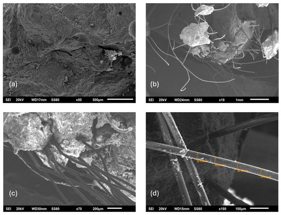
Figure 12.
SEM images of concrete specimens: (a) plain (unreinforced) concrete; (b–d) concrete specimens reinforced with commercial monofilament polypropylene fibers, showing fiber distribution and interaction within the cementitious matrix.
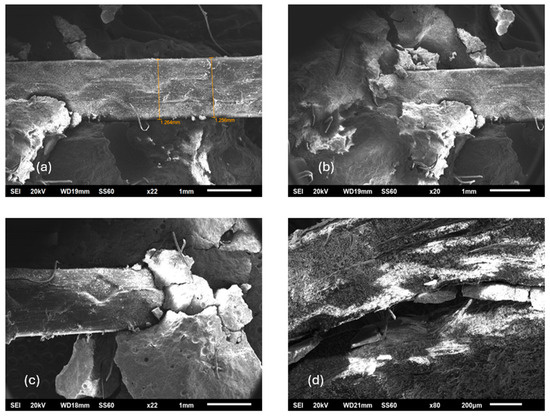
Figure 13.
SEM images of concrete reinforced with a combination of polypropylene fibers. (a–c) Concrete samples containing both commercial polypropylene fibers and polypropylene fiber braid, illustrating their combined dispersion and bonding within the matrix. (d) Fractured surface of the concrete specimen showing partial disintegration and pull-out of the polypropylene fiber braid after mechanical failure.
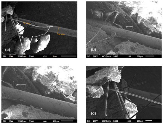
Figure 14.
SEM images of hybrid fiber-reinforced concrete. (a) Linear steel fibers used in the study. (b–d) Concrete specimens incorporating both commercial monofilament polypropylene fibers and linear steel fibers, showing their orientation and integration within the cementitious phase.
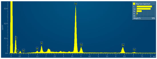
Figure 15.
EDXS elemental analysis of selected concrete specimen fragments (PFRC/PFBRC) reinforced with polypropylene fibers and polypropylene fiber braid.
These findings underscore the importance of fiber geometry and spatial distribution in determining the mechanical and microstructural behavior of fiber-reinforced concrete. By integrating experimental observations with microstructural analysis, this study contributes valuable insights into the design and development of next-generation high-performance cementitious composites that meet modern engineering demands.
4. Discussion
The results of this study clearly indicate that the incorporation of discontinuous steel and polymeric fibers in the concrete matrix leads to remarkable increases in mechanical performance in the form of the compressive strength, crack resistance and stability of the structure under bending loads. Specifically, polypropylene fibers, especially their braid variety (PFBRC), were significantly effective at bridging cracks and holding fragments together, as attested by both naked-eye observation and SEM testing. This finding is consistent with earlier results that have ascribed increased ductility and toughness to fiber-reinforced composites. Significantly, four-point bending tests revealed that while steel fibers alone were not found to offer considerable strength improvements, their combined effect when used with polypropylene fibers was apparent. The blend provided a more even balance of properties combining the tensile strength of steel and crack growth resistance in polypropylene. Furthermore, the most stable AE responses were observed in the hybrid specimens (PFRC/PFBRC/SFRC), which exhibited gradual energy release prior to failure, indicating delayed crack advance.
Compression tests also showed that on its own, the use of polypropylene fibers does not significantly improve compressive strength but, when incorporated with steel fibers, the carrying capacity is significantly improved. This shows that polypropylene fibers play a more complex role in influencing the post-cracking response of concrete and microscale cohesion than acting as significant load-carrying entities. Microstructurally, SEM imaging confirmed the uniform distribution and interlock of the fibers within the cementitious matrix. Polypropylene fibers in particular demonstrated strong adhesion with the matrix, the pinning of small particles and improvement in homogeneity. Such results confirm that the careful selection and combination of fiber types, lengths and dosages can yield highly tailored concrete mixtures to fulfill specific structural and durability requirements.
The findings of the research suggest directions for the future optimalization of hybrid fiber-reinforced concretes (HyFRC) in seismic regions or infrastructure building where dissipation of energy, crack control and durability for the long term are the most important issues. Future research has to investigate the behavior of these composites under cyclic loading, freeze–thaw exposure and long-term aging, as well as the economic and environmental aspects of the employment of fibers and recycling.
5. Conclusions
This study investigated the mechanical and microstructural performance of hybrid fiber-reinforced concrete (HyFRC) incorporating polypropylene fibers, polypropylene fiber braid and steel fibers. Maximum compressive strength was attained at 56.7 MPa for mixtures containing steel and polypropylene fiber braid (FB-ST), representing an increase of 59% over the plain sample. Samples using commercial polypropylene fibers alone reached the highest flexural strength in four-point bending at 20,159 N, nearly double that of the control specimen. Hybrid combinations, such as PP-ST and FB-ST mixes, also achieved compressive strengths exceeding 46 MPa, confirming a positive synergistic effect between fiber types. The results demonstrate that polypropylene fibers, and especially the braid form, were effective in bridging cracks and retaining cementitious fragments, thereby enhancing ductility and post-cracking behavior. Steel fibers contributed to higher compressive strength, though their influence on flexural capacity under four-point bending was less pronounced due to fiber orientation and dispersion effects. The observed increase in compressive strength for mixes containing steel fiber is consistent with the fibers’ role in restricting microcrack growth under triaxial compression. However, four-point bending load capacity is predominantly governed by the fibers’ effectiveness in bridging macrocracks in the tensile zone. The lack of a significant increase in bending peak load suggests limited fiber engagement across the critical crack plane—most likely due to orientation, insufficient dosage at the critical section, or pull-out dominated failure. Nevertheless, when combined in hybrid systems, the two fiber types acted synergistically, leading to improved load-bearing capacity and more stable performance. Acoustic emission monitoring confirmed that hybrid mixes exhibited a more gradual release of energy during loading, indicating enhanced crack control and delayed propagation compared to single-fiber systems. The compressive strength of hybrid specimens exceeded 50 MPa, highlighting the positive interaction between polymeric and steel fibers. Complementary SEM and EDXS analyses supported these findings by revealing effective fiber–matrix interlock, uniform distribution and retention of cementitious fragments at the interface, which collectively explain the improved macroscale behavior. Overall, the study demonstrates that the strategic combination of polymeric and steel fibers can significantly improve the reliability of fiber-reinforced composites, providing a balanced enhancement of strength, toughness and crack resistance. These results suggest that hybrid fiber-reinforced concrete has strong potential for demanding structural applications, such as infrastructure in seismic regions or structures exposed to cyclic loading, where both strength and durability are critical. Future research should focus on long-term durability under freeze–thaw cycles, cyclic loading and aging conditions, as well as the optimization of fiber ratios to tailor performance for specific engineering applications.
Author Contributions
Conceptualization, G.P., T.E.M., N.E.Z. and K.G.K.; methodology, G.P., T.E.M., N.E.Z. and K.G.K.; software, G.P.; validation, G.P., D.M., D.E. and P.P.; formal analysis, G.P.; investigation, G.P., G.P. and K.G.K.; resources, G.P.; data curation, G.P.; writing—original draft preparation, G.P., P.P. and K.G.K.; writing—review and editing, G.P.; visualization, G.P.; supervision, K.G.K., T.E.M. and N.E.Z.; project administration, N.E.Z. and T.E.M.; funding acquisition, N.E.Z. All authors have read and agreed to the published version of the manuscript.
Funding
This research received no external funding.
Data Availability Statement
The original contributions presented in this study are included in the article. Further inquiries can be directed to the corresponding author.
Acknowledgments
The authors would like to thank ALPHA TEST P.C.L., Spata, Attica, Greece, for support in conducting the compressive strength tests and DOMYLCO CONSTRUCTION CHEMICALS Ltd., for providing the commercial polypropylene fibers.
Conflicts of Interest
The authors declare no conflicts of interest.
References
- Gupta, S.; Kua, H.W.; Pang, S.D. Autonomous repair in cementitous material by combination of superabsorbent polymers and polypropylene fibres: A step towards sustainable infrastructure. arXiv 2017, arXiv:1706.02680. [Google Scholar] [CrossRef]
- Mardani-Aghabaglou, A.; Sezer, G.I.; Ramyar, K. Comparison of fly ash, silica fume and metakaolin from mechanical properties and durability performance of mortar mixtures view point. Constr. Build. Mater. 2014, 70, 17–25. [Google Scholar] [CrossRef]
- Zhu, Q. CO2 Abatement in the Cement Industry; Research Report CCC/184; IEA Clean Coal Centre: London, UK, 2011. [Google Scholar]
- Czarnecki, L. Concrete-Polymer Composites in Circular Economy: Proceedings of the 17th International Congress on Polymers in Concrete (ICPIC 2023); Springer Nature: London, UK, 2024; Volume 61. [Google Scholar]
- Liu, J.; Xu, W.; Li, G.; Chen, B.; Xiao, Y.; Huang, H.; Chen, J. Performance and Applications of Polymer Fiber Rubber-Reinforced Concrete in Civil Engineering: A State-of-the-Art Review. Polymers 2025, 17, 970. [Google Scholar] [CrossRef]
- Spadea, S.; Farina, I.; Carrafiello, A.; Fraternali, F. Recycled nylon fibers as cement mortar reinforcement. Constr. Build. Mater. 2015, 80, 200–209. [Google Scholar] [CrossRef]
- Yang, K.-H.; Jung, Y.-B.; Cho, M.-S.; Tae, S.-H. Effect of supplementary cementitious materials on reduction of CO2 emissions from concrete. J. Clean. Prod. 2015, 103, 774–783. [Google Scholar] [CrossRef]
- Shi, J. Fiber-Reinforced Polymers and Fiber-Reinforced Concrete in Civil Engineering. Buildings 2023, 13, 1755. [Google Scholar] [CrossRef]
- Khan, S.; Khattak, S.; Khan, H. Composite Fibers in Concrete: Properties, Challenges, and Future Directions. Eng. Proc. 2023, 44, 17. [Google Scholar]
- Thomoglou, A.K.; Falara, M.G.; Gkountakou, F.I.; Elenas, A.; Chalioris, C.E. Smart cementitious sensors with nano-, micro-, and hybrid-modified reinforcement: Mechanical and electrical properties. Sensors 2023, 23, 2405. [Google Scholar] [CrossRef]
- Simões, T.; Costa, H.; Dias-da-Costa, D.; Júlio, E. Influence of type and dosage of micro-fibres on the physical properties of fibre reinforced mortar matrixes. Constr. Build. Mater. 2018, 187, 1277–1285. [Google Scholar] [CrossRef]
- Demakos, C.B.; Repapis, C.C.; Drivas, D.P. Experimental investigation of shear strength for steel fibre reinforced concrete beams. Open Constr. Build. Technol. J. 2021, 15, 81–92. [Google Scholar] [CrossRef]
- Bentur, A.; Mindess, S. Fibre Reinforced Cementitious Composites; CRC Press: Boca Raton, FL, USA, 2006. [Google Scholar]
- Kos, Ž.; Kroviakov, S.; Mishutin, A.; Poltorapavlov, A. An experimental study on the properties of concrete and fiber-reinforced concrete in rigid pavements. Materials 2023, 16, 5886. [Google Scholar] [CrossRef]
- Ohtsu, M. Acoustic Emission and Related Non-Destructive Evaluation Techniques in the Fracture Mechanics of Concrete: Fundamentals and Applications; Woodhead Publishing: Cambridge, UK, 2020. [Google Scholar]
- ACI 211.2-98; Standard Practice for Selecting Proportions for Structural Lightweight Concrete [Reapproved 2004]. American Concrete Instiute (ACI): Farmington Hills, MI, USA, 2002; 20p, ISBN 9780870313301.
- EN 12350-2:2009; Testing Fresh Concrete—Part 2: Slump Test. European Committee for Standardization (CEN): Brussels, Belgium, 2009.
- Mpalaskas, A.; Aggelis, D.; Matikas, T. Monitoring the fracture behavior of epoxy resin repaired fiber reinforced concrete specimens by acoustic emission. In Sensors and Smart Structures Technologies for Civil, Mechanical, and Aerospace Systems 2021; SPIE: Bellingham, WA, USA, 2021; pp. 461–474. [Google Scholar]
- Mpalaskas, A.C.; Matikas, T.E. Acoustic emission monitoring of the fracture behavior of mortar specimens fabricated using recycled concrete aggregates. In Smart Structures and NDE for Industry 4.0, Smart Cities, and Energy Systems; SPIE: Bellingham, WA, USA, 2020; pp. 138–148. [Google Scholar]
- Grosse, C.U.; Ohtsu, M.; Aggelis, D.G.; Shiotani, T. Acoustic Emission Testing: Basics for Research–Applications in Engineering; Springer Nature: London, UK, 2021. [Google Scholar]
- Li, D.; Nie, J.-H.; Wang, H.; Yan, J.-B.; Hu, C.-X.; Shen, P. Damage location, quantification and characterization of steel-concrete composite beams using acoustic emission. Eng. Struct. 2023, 283, 115866. [Google Scholar] [CrossRef]
- Goldstein, J.I.; Newbury, D.E.; Michael, J.R.; Ritchie, N.W.; Scott, J.H.J.; Joy, D.C. Scanning Electron Microscopy and X-Ray Microanalysis; Springer: Berlin/Heidelberg, Germany, 2017. [Google Scholar]
- Egerton, R.F. Physical Principles of Electron Microscopy; Springer: Berlin/Heidelberg, Germany, 2005; Volume 56. [Google Scholar]
- Bozzola, J.J.; Russell, L.D. Electron Microscopy: Principles and Techniques for Biologists; Jones & Bartlett Learning: Burlington, MA, USA, 1999. [Google Scholar]
- Alhozaimy, A.; Soroushian, P.; Mirza, F. Mechanical properties of polypropylene fiber reinforced concrete and the effects of pozzolanic materials. Cem. Concr. Compos. 1996, 18, 85–92. [Google Scholar] [CrossRef]
- Siddique, R.; Khatib, J.; Kaur, I. Use of recycled plastic in concrete: A review. Waste Manag. 2008, 28, 1835–1852. [Google Scholar] [CrossRef]
- Li, V.C. On engineered cementitious composites (ECC) a review of the material and its applications. J. Adv. Concr. Technol. 2003, 1, 215–230. [Google Scholar] [CrossRef]
- Pujadas, P.; Blanco, A.; Cavalaro, S.; Aguado, A.; Grünewald, S.; Blom, K.; Walraven, J.C. Plastic fibres as the only reinforcement for flat suspended slabs: Parametric study and design considerations. Constr. Build. Mater. 2014, 70, 88–96. [Google Scholar] [CrossRef]
- Porfyriadou, G.; Moschovas, D.; Exarchos, D.; Kolovos, K.; Matikas, T.; Zafeiropoulos, N.E. Polypropylene Fibers for 3D Brace-Reinforced Concrete. Steps Civ. Constr. Environ. Eng. 2025, 3, 13–19. [Google Scholar] [CrossRef]
- Aggelis, D.G. Classification of cracking mode in concrete by acoustic emission parameters. Mech. Res. Commun. 2011, 38, 153–157. [Google Scholar] [CrossRef]
- Ren, H.; Li, T.; Ning, J.; Song, S. Analysis of damage characteristics of steel fiber-reinforced concrete based on acoustic emission. Eng. Fail. Anal. 2023, 148, 107166. [Google Scholar] [CrossRef]
- Li, B.; Xu, L.; Shi, Y.; Chi, Y.; Liu, Q.; Li, C. Effects of fiber type, volume fraction and aspect ratio on the flexural and acoustic emission behaviors of steel fiber reinforced concrete. Constr. Build. Mater. 2018, 181, 474–486. [Google Scholar] [CrossRef]
- Mpalaskas, A.C.; Matikas, T.E.; Aggelis, D.G.; Alver, N. Acoustic emission for evaluating the reinforcement effectiveness in steel fiber reinforced concrete. Appl. Sci. 2021, 11, 3850. [Google Scholar] [CrossRef]
- Aggelis, D.G.; Soulioti, D.V.; Sapouridis, N.; Barkoula, N.; Paipetis, A.; Matikas, T. Acoustic emission characterization of the fracture process in fibre reinforced concrete. Constr. Build. Mater. 2011, 25, 4126–4131. [Google Scholar] [CrossRef]
- Mpalaskas, A.C.; Kytinou, V.K.; Zapris, A.G.; Matikas, T.E. Optimizing building rehabilitation through nondestructive evaluation of fire-damaged steel-fiber-reinforced concrete. Sensors 2024, 24, 5668. [Google Scholar] [PubMed]
- Tan, G.; Zhu, Z.; Wang, W.; Wu, C.; Ou, J.; Cui, G.; Zhang, D. Flexural ductility and crack-controlling capacity of polypropylene fiber reinforced ECC thin sheet with waste superfine river sand based on acoustic emission analysis. Constr. Build. Mater. 2021, 277, 122321. [Google Scholar] [CrossRef]
- Chaturvedi, R.; Singh, P.K.; Sharma, V.K. Analysis and the impact of polypropylene fiber and steel on reinforced concrete. Mater. Today Proc. 2021, 45, 2755–2758. [Google Scholar] [CrossRef]
- Afroughsabet, V.; Biolzi, L.; Ozbakkaloglu, T. High-performance fiber-reinforced concrete: A review. J. Mater. Sci. 2016, 51, 6517–6551. [Google Scholar] [CrossRef]
- Joo Kim, D.; Naaman, A.E.; El-Tawil, S. Comparative flexural behavior of four fiber reinforced cementitious composites. Cem. Concr. Compos. 2008, 30, 917–928. [Google Scholar] [CrossRef]
- Sivakumar, A.; Santhanam, M. Mechanical properties of high strength concrete reinforced with metallic and non-metallic fibres. Cem. Concr. Compos. 2007, 29, 603–608. [Google Scholar] [CrossRef]
- Mohammadi, Y.; Singh, S.; Kaushik, S. Properties of steel fibrous concrete containing mixed fibres in fresh and hardened state. Constr. Build. Mater. 2008, 22, 956–965. [Google Scholar] [CrossRef]
- Santos, A.G.a.; Rincón, J.M.; Romero, M.; Talero, R. Characterization of a polypropylene fibered cement composite using ESEM, FESEM and mechanical testing. Constr. Build. Mater. 2005, 19, 396–403. [Google Scholar] [CrossRef]
- Liu, J.; Jia, Y.; Wang, J. Experimental study on mechanical and durability properties of glass and polypropylene fiber reinforced concrete. Fibers Polym. 2019, 20, 1900–1908. [Google Scholar] [CrossRef]
Disclaimer/Publisher’s Note: The statements, opinions and data contained in all publications are solely those of the individual author(s) and contributor(s) and not of MDPI and/or the editor(s). MDPI and/or the editor(s) disclaim responsibility for any injury to people or property resulting from any ideas, methods, instructions or products referred to in the content. |
© 2025 by the authors. Licensee MDPI, Basel, Switzerland. This article is an open access article distributed under the terms and conditions of the Creative Commons Attribution (CC BY) license (https://creativecommons.org/licenses/by/4.0/).