Review

Computational and Experimental Insights into Blast Response and Failure Mechanisms of Square, Rectangular and Circular Reinforced Concrete Columns: A State-of-the-Art Review

by
S. M. Anas
1,*,
Rayeh Nasr Al-Dala’ien
2,
Mohammed Benzerara
3,* and
Mohammed Jalal Al-Ezzi
4,5
1
Department of Civil Engineering, Jamia Millia Islamia, New Delhi 110025, India
2
Civil Engineering Department, College of Engineering, Al-Balqa Applied University (BAU), Salt 19117, Jordan
3
Materials, Geomaterials and Environment Laboratory (LMGE), Faculty of Technology, Department of Civil Engineering, Badji Mokhtar-Annaba University, P.O. Box 12, Annaba 23000, Algeria
4
Civil Engineering Department, College of Engineering, Universiti Tenaga Nasional, Kajang 43000, Malaysia
5
Civil Engineering Department, University of Bilad AL-Rafidain, Baqubah 32001, Iraq
*
Authors to whom correspondence should be addressed.
Buildings 2025, 15(21), 3928; https://doi.org/10.3390/buildings15213928
Submission received: 24 September 2025 / Revised: 24 October 2025 / Accepted: 27 October 2025 / Published: 30 October 2025
(This article belongs to the Section Building Structures)

Abstract

Blast damage to structural members poses serious risks to both buildings and people, making it important to understand how these elements behave under extreme loads. Columns in reinforced concrete (RC) structures are especially critical, as their sudden failure can trigger progressive collapse, unlike beams or slabs that have more redundancy. This state-of-the-art review brings together the current knowledge of the blast response of RC columns, focusing on their failure patterns, dynamic behavior, and key loading mechanisms. The studies covered include experiments, high-fidelity numerical simulations, emerging machine learning approaches, and analytical models for columns of different shapes (square, rectangular, circular) and strengthening methods, such as fiber reinforcement, steel-concrete composite confinement, and advanced retrofitting. Composite columns are also reviewed to compare their hybrid confinement and energy-absorption advantages over conventional RC members. Over forty specific studies on RC columns were analyzed, comparing the results based on geometry, reinforcement detailing, materials, and blast conditions. Both near-field and contact detonations were examined, along with factors like axial load, standoff distance, and confinement. This review shows that RC columns respond very differently to blasts depending on their shape and reinforcement. Square, rectangular, and circular sections fail in distinct ways. Use of ultra-high-performance concrete, steel fibers, steel-concrete composite, and fiber-reinforced polymer retrofits greatly improves peak and residual load capacity. Ultra-high-performance concrete can retain a significantly higher fraction of axial load (often >70%) after strong blasts, compared to ~40% in conventional high-strength RC under similar conditions. Larger sections, closer stirrups, higher transverse reinforcement, and good confinement reduce spalling, shear failure, and mid-height displacement. Fiber-reinforced polymer and steel-fiber wraps typically improve residual strength by 10–15%, while composite columns with steel cores remain stiff and absorb more energy post-blast. Advanced finite element simulations and machine learning models now predict displacements, damage, and residual capacity more accurately than older methods. However, gaps remain. Current design codes of practice simplify blast loads and often do not account for localized damage, near-field effects, complex boundary conditions, or pre-existing structural weaknesses. Further research is needed on cost-effective, durable, and practical retrofitting strategies using advanced materials. This review stands apart from conventional literature reviews by combining experimental results, numerical analysis, and data-driven insights. It offers a clear, quantitative, and comparative view of RC column behavior under blast loading, identifies key knowledge gaps, and points the way for future design improvements.

1. Introduction

In conventional structural design practice, blast loading is generally not included in the standard load combinations outlined in design building codes [1]. Such extreme scenarios are typically considered only for high-risk facilities, like petrochemical plants, or for critical structures such as embassies, defense sites, and major transportation hubs, where accidental or deliberate blasts could have serious consequences [1,2]. Consequently, the core principles of explosions, including detonation, shock wave propagation, reflection/transmission of blast waves, and their interactions with structural elements, are rarely covered in standard engineering education or training, except in specialized courses.
Over the past few years, understanding how concrete structures behave under blast loads has become increasingly important [1]. This is largely due to the rise in accidental explosions as well as intentional attacks [1]. Concrete shows a very complex response under such extreme conditions, which may include high strain rates, spalling, scabbing, and sometimes even total structural failure. These effects occur because of the propagation and reflection of shock waves, along with the material’s strain-rate-dependent resistance. Experimental investigations and post-incident analyses have consistently highlighted the devastating effects of blast loads on structures [1,2,3,4]. Reported incidents include severe civilian casualties during attacks on public and strategic sites [5], along with extensive structural damage and compromised functionality in essential infrastructure like bridges and transport networks [6,7].
Blast loading is regarded as one of the most severe forms of dynamic loading. It produces extremely high strain rates, usually between 102 s−1 and 104 s−1 [1,2]. In comparison, other types of structural loadings result in much lower strain rates, as illustrated in Figure 1 [1]. Loads that act slowly, like the effect of gravity or gradual settlement of soil, cause very low strain rates, usually between 10−6 s−1 and 10−3 s−1. Earthquakes, though dynamic, are still much slower than blasts. Their strain rates generally stay in the range of 10−3 s−1 to 10−1 s−1. On the other hand, sudden impacts, such as a vehicle hitting a column or a heavy object falling, lie in between these two extremes. Such cases usually produce strain rates starting around 1 s−1 and can go up to about 102 s−1. A special situation may also happen when a blast causes part of a structure, like an upper floor slab, to fail. The broken concrete from the slab can fall onto the floor below, combining the effects of blast and impact [2]. As a result, the lower structural members face both the force of falling debris and the secondary blast effects. In industrial environments, another possible scenario arises when a chemical fire or explosion causes sudden overpressure along with high thermal stress on nearby structural elements. This leads to a complex mix of fire, blast, and impact effects acting together. Similarly, in confined industrial or underground facilities, the repeated reflection, superposition, and channeling of blast waves within enclosed spaces can drastically increase the peak overpressure, impulse, and positive phase duration, subjecting structural elements to intensified multi-directional loads that far exceed those observed in open-field detonations.
In structural design, it is essential to know the types of loads that may act during the service life of a structure [2]. Earlier, blast loading was assumed to be an exceptional case [1]. But the present global scenario has made such extreme events more common, and hence it has become crucial to understand how blast-induced loads affect structures [1]. Blast effects generally consist of air-blast pressures, ground shocks, and fragment impacts. These components are most critical in near-field or close-in detonations, while far-field detonations usually expose structures only to air-blast pressure [8,9,10,11].
Table 1 describes how buildings are affected by explosions at different pressure levels and distances. It shows how the impact increases step by step, from small cracks in glass at lower pressures to complete structural failure and loss of life at very high pressures [1]. The table also links the pressure levels with possible human injuries and building responses. The values of overpressure and stand-off distance are collected from various reliable sources [12] to offer a general idea. However, it is noted that the actual response of a structure can differ based on many factors, such as the amount of explosive used, confinement of the blast, reflected pressure, type of ground surface, weather conditions, and the strength, ductility, and detailing of construction materials and reinforcements [1,2,3,12].
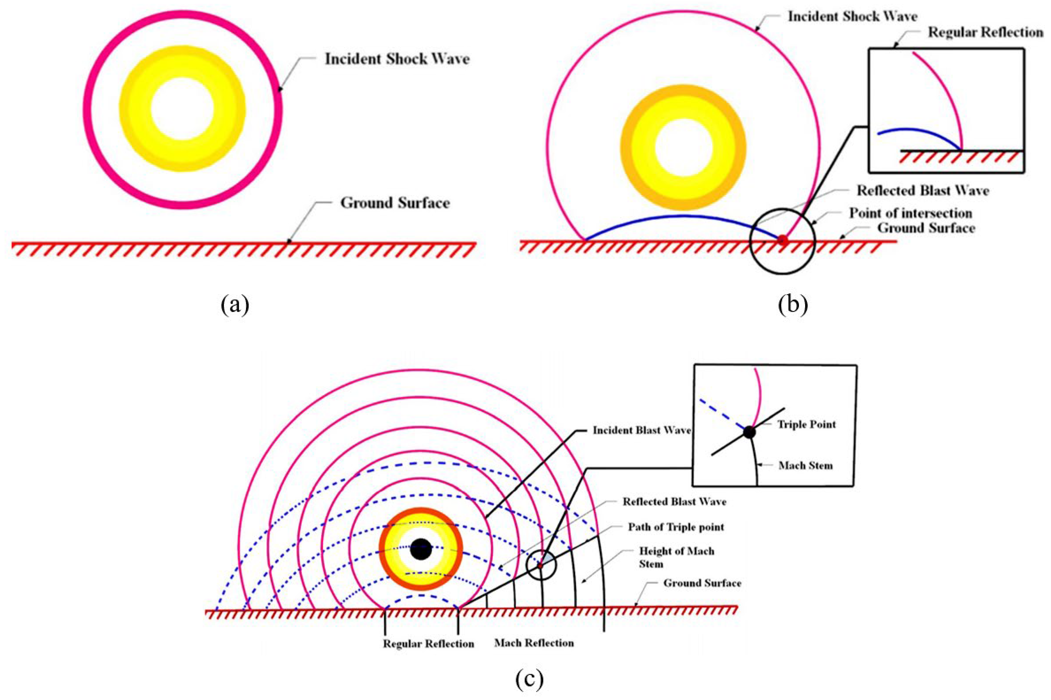
In a free-air burst, a sharp-fronted blast wave originates at the source and travels outward, as shown in Figure 2a (reported in [12]). When this wave hits the ground, it undergoes regular (or simple) reflection [10]. The incident and reflected waves meet at the surface, creating a stronger combined shock, as shown in Figure 2b [10,12]. Close to the ground, the flow acquires a strong vertical component. As the wave moves along the ground, these interactions form a secondary front called the Mach stem, as shown in Figure 2c [10]. This is known as Mach reflection. Although pressure varies across the height of the Mach stem, for preliminary design, the blast is usually idealized as a uniform plane wave. The height of this Mach stem generally increases as the wavefront travels outward. The point where the incident, reflected, and Mach waves intersect traces what is called the triple-point path [10,12]. The sources of Figure 2 include [9,10,12].
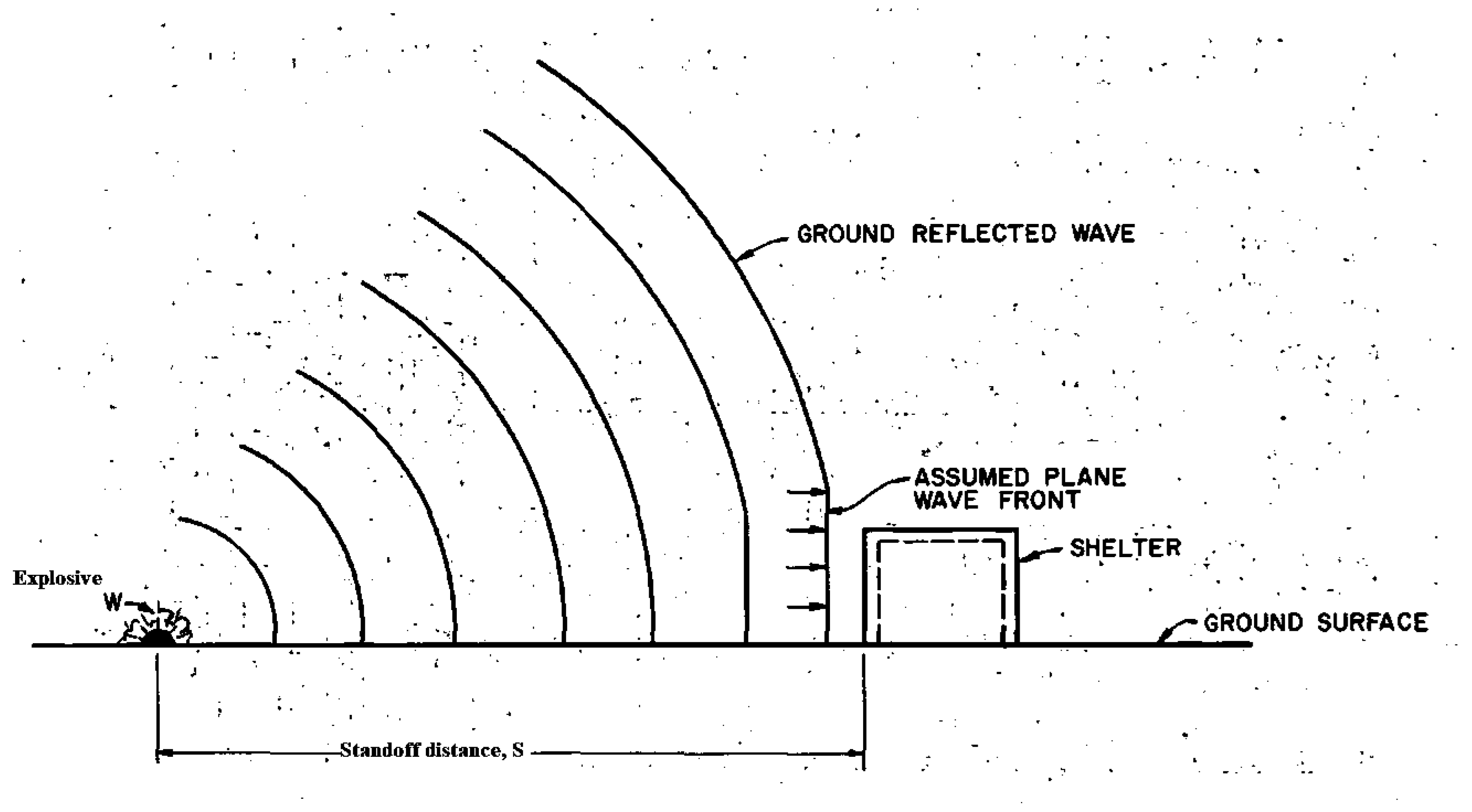
During a surface burst, the shock front behaves like a combination of the incident and reflected waves, moving almost parallel to the ground [11]. This combined front, called the Mach stem, causes a noticeable rise in peak overpressure near the surface. Because of this, targets on or close to the ground become more vulnerable, as shown in Figure 3 [11,13,14]. Structures located in this high-pressure zone experience stronger blast forces and face a higher risk of damage or failure.
A detailed numerical study on blast-column interaction was reported by Shi et al. (2007) [15,16] using ANSYS AUTODYN software. The study focused on factors like scaled distance, column stiffness, and the ratio of supported mass to column mass. It also studied how the size of the column and the type of cross-section, whether rectangular or circular, influence the response. Based on this, specific formulae were developed to calculate blast pressure, impulse, and the variation in reflected pressure with time on both the front and rear faces of the column [15]. The findings showed that column stiffness had a relatively small effect on blast pressure and impulse because of the very short loading duration. In contrast, column width had a clear impact, with reflected pressure increasing as the width grew, up to a certain limit, after which the effect became stable. It was also observed that circular columns caused lower reflection on the front face but transferred higher loads to the rear face when compared with rectangular columns [15].
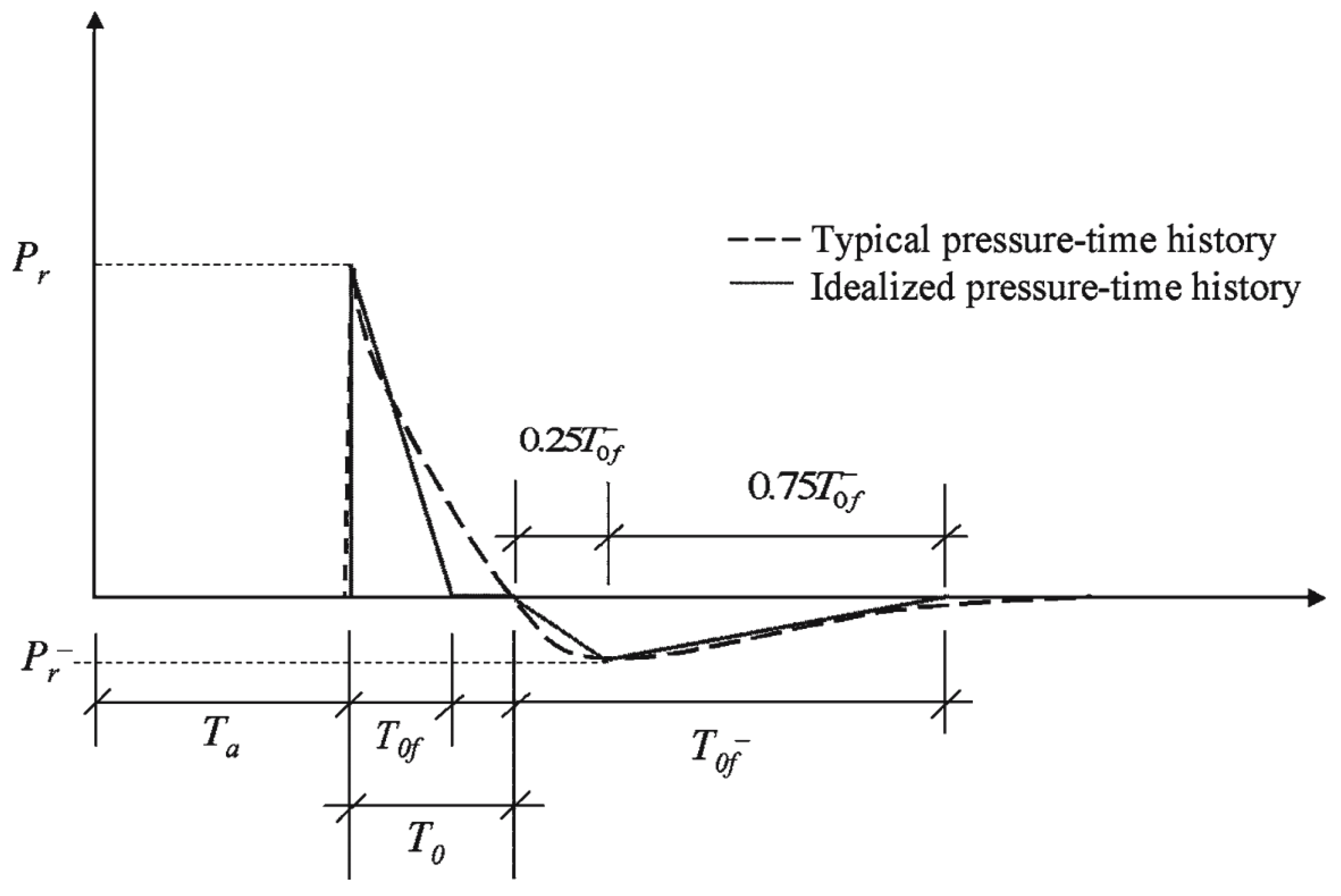
Blast loads are typically described by two distinct pulses: the positive and the negative, as shown in Figure 4 (Shi et al., 2007 [15,16]). The positive pulse shows a sharp rise in pressure at the wavefront followed by a decay to ambient level PO. It is defined by parameters such as arrival time (Ta), fictitious positive phase duration (T0f), and the reflected peak pressure (Pr) [15]. This positive phase exerts severe effects on both industrial and civil structures, since keeping all buildings isolated from possible explosive sources is not practical [15]. The negative phase, though relatively less intense, can influence the direction of failure and structural fragmentation. Its magnitude was also characterized using amplification and reduction factors [15].
The fictitious duration T0f is generally shorter than the actual duration T0, creating a small-time gap before the suction phase begins T 0 f [15]. This gap should be preserved in analysis for accurate representation of the loading sequence. Shi et al. (2007) [15] proposed an empirical model to predict the reflected pressure profile. The model was checked against the experimental blast test results. The simulated data matched well with the tests, proving that AUTODYN can be relied upon for such applications. This model continues to serve as a practical reference for engineers working on blast-resistant designs [15].
P t = 0 , 0 t < T a P r , T a P r P r T 0 f t T a , T a t T a + T 0 f 0 , T a + T 0 f t T a + T 0 P r 0.25 T 0 f   t T a T 0 , T a + T 0 T a + T 0 + 0.25 T 0 f P r P r 0.75 T 0 f   t T a T 0 0.25 T 0 f , T a + T 0 + 0.25 T 0 f t T a + T 0 + T 0 f 0 T a + T 0 + T 0 f t
P(t) denotes the reflected blast pressure at time “t”, Pr is the actual negative (underpressure) peak, given in kilopascals (kPa), and T a , T 0 f , T 0 , and T 0 f are time parameters measured in milliseconds (ms), and they relate to wave arrival instants and phase durations [15].
Numerical results indicate clear geometric effects on blast-column interaction. A circular column reflects less of the incident wave but diffracts it more, compared with a rectangular column [15]. The reflected pressure on the face of the circular column that faces the explosion is smaller in magnitude [2,3]. However, the pressure on the far (distal or rear) face of the circular column can be comparable to or exceed that of the rectangular column, depending on the standoff distance and wave diffraction characteristics. The time delay between shock arrival at the incident face and at the distal face is shorter for the circular section than for the rectangular section [15,16].
Column dimensions and the ratio of supported mass to column mass showed little influence on the overall blast-structure interaction. By contrast, column width did affect the amplification factors on the incident face. Increasing the width tends to increase the local amplification of the shock front acting on the face that first encounters the wave.
For scaling blast loadings, the Hopkinson-Cranz (Kennedy, 1946) [17] approach uses the scaled distance Z, which relates explosive weight and standoff distance. The common definition is [17]:
Z = R W 1 3
where R is the standoff distance (m) and W is the TNT-equivalent charge weight (kg). Z is expressed in units of m·kg−1/3 and is widely used to predict peak pressures, impulse, and other blast parameters from scaled empirical curves [1,10,17].
Blast loads are generally classified as near-field or far-field, depending on the scaled distance [1] (Figure 5, adapted from Hao et al. (2016) [1]). For far-field explosions, the blast pressure reflects and spreads evenly over the structure [1]. When the scaled distance is smaller, the force becomes highly concentrated near the blast, which is typical of near-field detonation [1].
Different researchers and standards define this classification in different ways [3]. Enstock and Smith (2007) [18] describe a close-in or near-field explosion as a charge detonated at a very short range from a structure, although the exact limit of this “short range” is not consistent across literature. ASCE/SEI 59-11 [19] guideline specifies near-field detonations as those occurring at scaled distances below 1.20 m/kg1/3. Gel’fand et al. (2004) [20] suggested that if the characteristic dimension of the charge is taken as r0, then the near-field region (Rn) may be considered within 0 < Rn < 20r0. The near-field region is described in different ways [1]. Some define it using scaled distance, where the standoff is normalized by the charge mass. Others consider geometric scaling, relating it to the size of the charge. In practical terms, the definition used depends on the analytical model or the design standard being followed.
Indian and international blast design codes such as IS 4991 [13], ESL-TR 87-57 [21], TM 5-855-1 [8], TM 5-1300 [9], and UFC 3-340-02 [10] provide reasonably reliable data for scaled distances above ~0.40 m/kg1/3 (or ~1 ft/lb1/3). Below this threshold, the Kingery-Bulmash (K-B) [22] empirical curves are less dependable, and such cases are treated as close-in detonations. The K-B dataset comes from spherical free-air bursts and does not fully reflect the complex behavior of shocks near an explosion, especially those influenced by ground interaction and reflections. Close to the blast, effects like strong nonlinear reflections, ground interaction, and increased confinement pressures become significant. Because of this, standard code predictions often underestimate peak overpressures and impulses in the near-field or close-in detonations. For more accurate assessment, high-fidelity numerical simulations, such as computational fluid dynamics-based methods using AUTODYN or Arbitrary Lagrangian-Eulerian (ALE) solvers, or experimental calibration are usually needed.
Blast effects in the near field are highly localized [1]. Common failure mechanisms observed include [23]:
  • Spalling: Material is ejected from the rear face of concrete due to high tensile stresses caused by stress wave reflections.
  • Scabbing: Fragments of concrete break away from the back face when compressive stress waves surpass the residual tensile strength.
  • Shear plug formation: A localized shear failure occurring in RC slabs or walls, caused by concentrated blast pressures over small areas.
  • Punching shear failure: Localized penetration or perforation, often in thin plates or slabs, resulting from high-intensity, short-duration pressure pulses [23].
These local damages near the blast are largely influenced by the material’s strain-rate sensitivity, stress-wave propagation, and the standoff distance of the explosion. Unlike mid- or far-field blasts, where overall flexural or membrane action may control response, near-field blasts usually trigger severe local failures before any significant global deformation takes place [1,23].
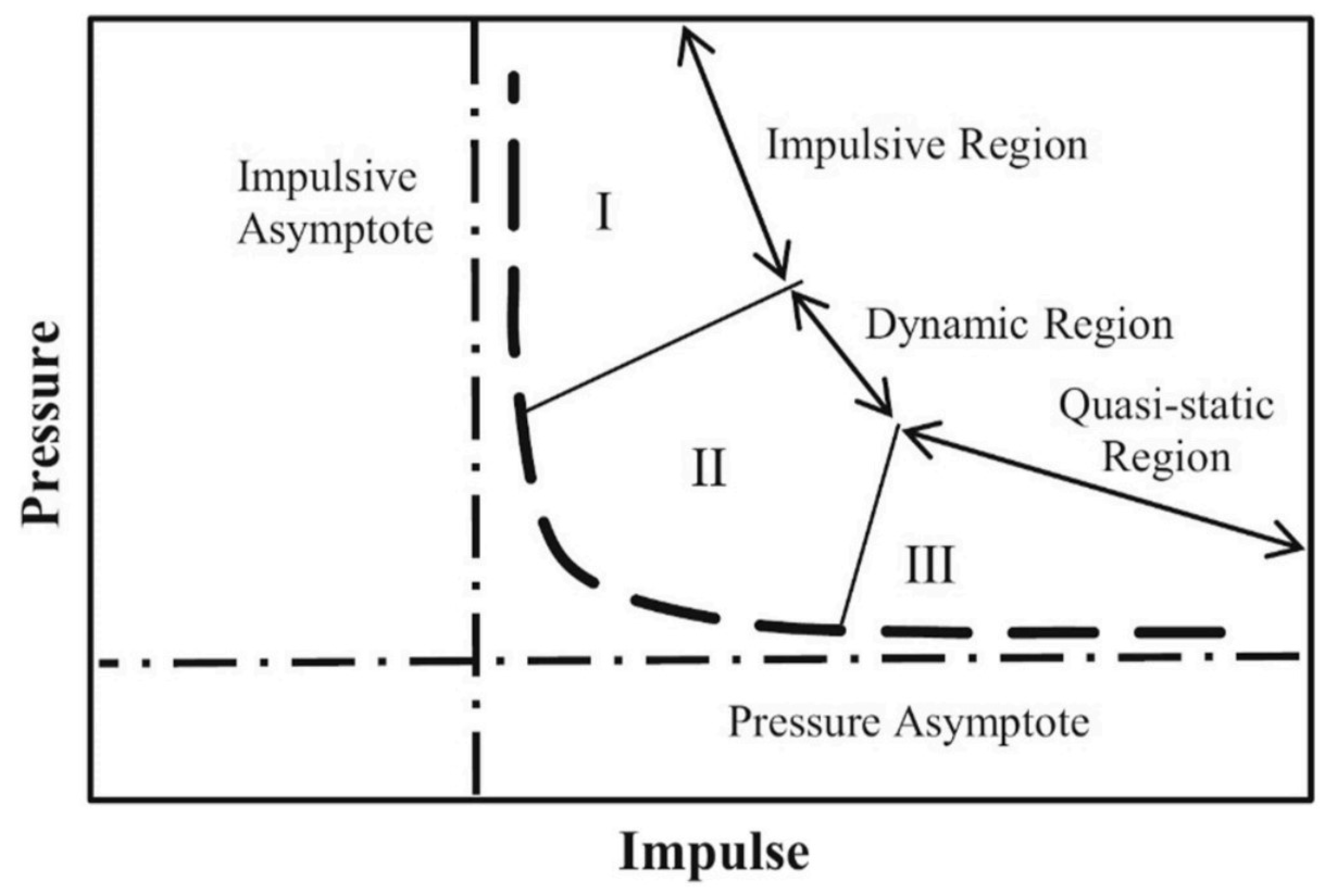
Blast loading is often explained using pressure-impulse (P-I) diagrams, which show the connection between peak reflected overpressure (P) and specific impulse (I) (see Figure 6 [1]). These diagrams are widely used in protective structural engineering to set failure limits, guide design, and check how structures behave under different blast scenarios [24,25,26,27].
A P-I diagram typically has two asymptotes: a vertical impulsive asymptote and a horizontal pressure asymptote. These divide the response into three regimes, impulsive, dynamic, and quasi-static, depending on how the blast duration compares with the structure’s natural period, Tn [1].
  • Impulsive Region (tdTn): The blast is very short compared to the structural vibration period. The response is mostly controlled by inertia. Deformation depends more on the impulse than on the peak pressure [28]. Single-degree-of-freedom (SDOF) models are often used here, treating the blast as a rapid momentum transfer.
  • Dynamic Region (tdTn): When the blast duration is similar to the natural period, both pressure and impulse affect the response. This is the most complex region, with possible resonance or dynamic amplification [1,28]. Time-history analysis using SDOF or finite element (FE) models is usually needed to capture structural behavior.
  • Quasi-static Region (tdTn): For long-duration blasts, the load changes slowly compared to the structure’s response. In this case, deformation is mainly driven by peak pressure [1]. The structure develops significant plastic deformations before unloading; so, the response can be treated as quasi-static.
Many international agencies have issued detailed manuals for protecting buildings from blast effects. Important references include the U.S. Department of the Army [9], U.S. Department of Defense [10], U.S. General Services Administration [25], FEMA guidelines [26,29], and the standards of the American Society of Civil Engineers [27]. These documents provide broad design philosophies and practical approaches. However, dedicated design codes specifically addressing blast-resistant detailing of structural members are still very limited [1,2].
Most available recommendations rely heavily on simplified methods such as SDOF approach [1]. This method captures the dynamic response of beams, slabs, and columns under high strain rates, but it does not fully capture strain-rate dependent material behavior, complex member interactions, progressive collapse, energy dissipation mechanisms, or near-field blast effects in RC and steel structures. Table 2 presents a summary of provisions suggested in the major manuals and standards for structures exposed to blast loading, highlighting their scope and limitations [1].
Most of the commonly used design codes, ASCE 59-11 [19], UFC 3-340-02 [10], Eurocode (EN 1991-1-7 [32]), IS 4991:1968 [13], and ACI 349 [33]/ACI 370R-14 [34], show similar shortcomings when applied to modern blast-resistant design. These standards mainly depend on empirical formulas and simplified SDOF or equivalent static methods. Such approaches usually assume uniform or triangular pressure pulses, which do not reflect the actual pressure-time variations caused by reflections, ground interaction, or structural continuity. They also tend to overlook localized damage modes like spalling, scabbing, and shear plugging. Although some documents include limited provisions for dynamic amplification or strain-rate effects, these treatments remain simplified and do not adequately address material degradation such as stiffness loss, cracking, or fragmentation. This can lead to either overly conservative or sometimes unconservative predictions, depending on the scenario. Guidance for strengthening with modern materials like CFRP, UHPFRC, or FRCM is missing or adapted from static load conditions, which may not be reliable. Moreover, these standards rarely consider time-dependent fluid–structure interaction or three-dimensional confinement effects. Such gaps become especially critical in near-field blasts and high strain-rate situations, where accurate modeling and realistic material behavior are essential for reliable design and retrofit solutions.
Simplified approaches outlined in [9,10] for predicting structural response rely largely on SDOF representations [1]. These classical models are typically expressed using pressure–impulse (P-I) diagrams and breach curves [1,23]. However, using such models requires careful attention to the underlying assumptions about blast loading and column behavior [23].
Key assumptions include:
  • The blast originates from large explosive charges positioned at a standoff distance sufficient to ensure uniform pressure distribution along the column height, as assumed in SDOF models, though real pressure gradients may occur.
  • The column’s lateral response is primarily flexure-dominated, with bending governing failure mechanisms.
  • Local core fracturing of concrete is minimal and does not significantly influence the overall response.
  • Flexural deformation criteria are suitable indicators for evaluating column performance under blast action [1,9,10].
Deviation from these assumptions can make the predictions from such simplified models highly unreliable [23]. Strong or nearby blasts can produce severe structural damage, even to large columns [23]. Interestingly, increasing column size does not always translate to better protection for close-in detonations, since failure mechanisms shift from flexural to local shear or spalling under high-intensity blasts [23].

1.1. Methods for Simulating Blast Loads

Several methods are available to simulate blast loads on structures, each using different experimental setups [1]:
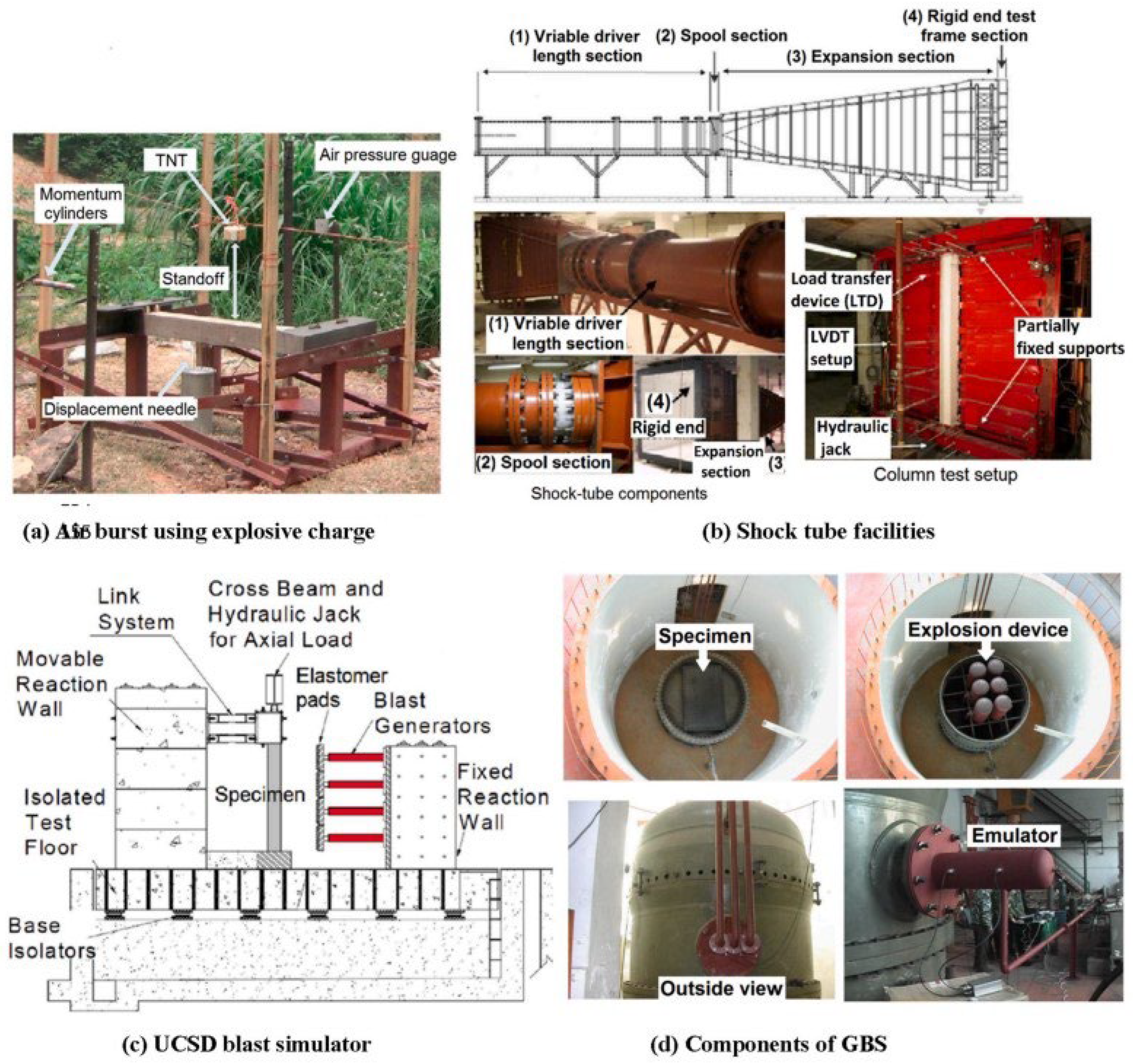
  • Air burst using explosive charges (Figure 7a [1]): In this approach, structures are subjected to controlled explosions, often using TNT or other chemical compounds. The explosives vary in geometry, size, and weight, allowing researchers to study different blast intensities and structural responses [35]. Pressure transducers and displacement gauges are commonly used to record pressure–time histories and specimen movements (Figure 7a).
  • One major advantage of this method is that it can closely replicate real blast effects, capturing even complex pressure patterns and fragments. However, it also comes with several drawbacks. The setup is costly and risky to operate, testing sites are limited, and results often vary because of unpredictable explosive behavior.
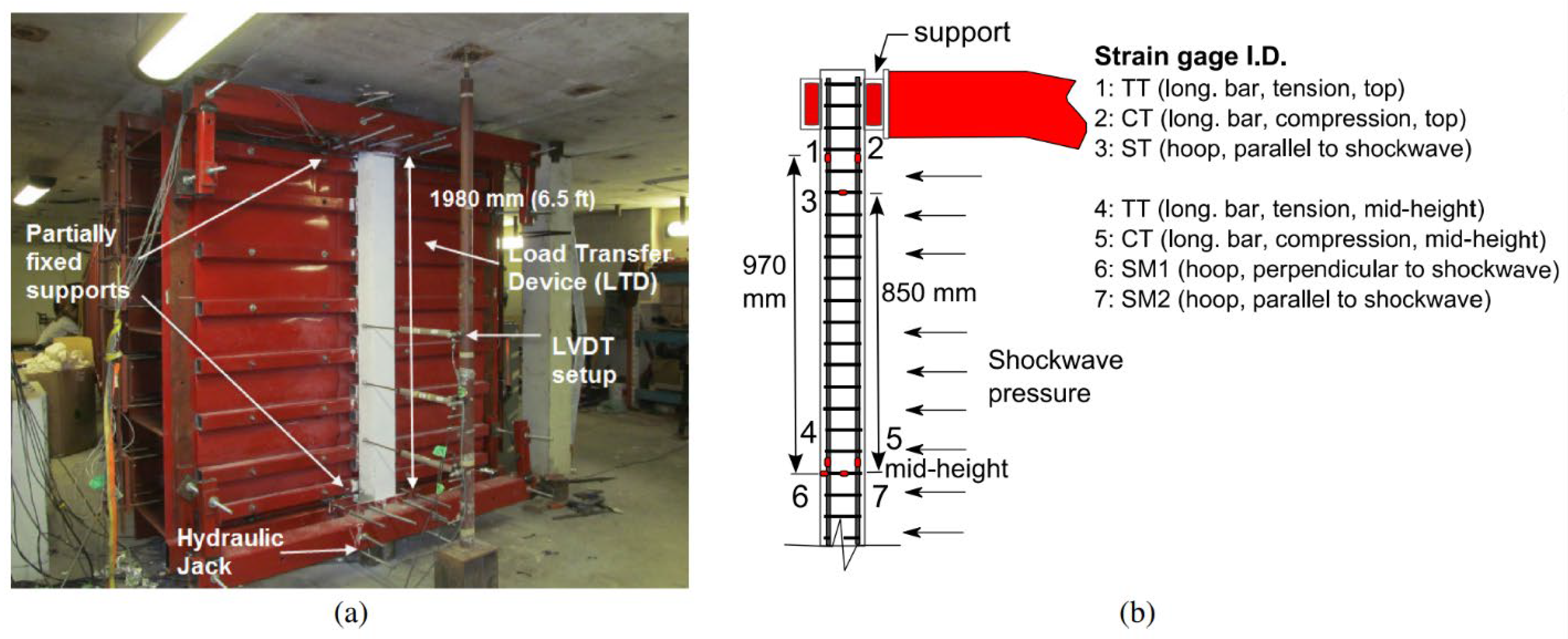
  • Shock tube testing (Figure 7b [1]): Shock tubes generate high-pressure waves inside a compression chamber. These waves are then released through a variable-length driver toward the target. A differential pressure diaphragm in the spool section controls the firing. The generated shockwaves travel along an expansion section before striking the target, enabling precise study of blast effects on structures [36]. This approach helps in creating consistent and repeatable loading conditions. Instrumentation such as load cells, LVDTs, and strain gauges are used to measure responses (Figure 7b).
  • The main advantages are the ability to repeat blast conditions with precision and to record accurate measurements using LVDTs, load transfer devices, and hydraulic jacks. However, shock tubes often fail to reproduce certain secondary effects such as fragmentation or multiple reflected pressure waves that occur in real explosions.
  • UCSD blast simulator (Figure 7c [1]): Developed at the University of California, San Diego, this facility uses hydraulically driven actuators to mimic distributed blast loads. Elastomer pads transfer these simulated impact loads to structural specimens, providing a controlled and repeatable experimental environment [37]. The system includes both movable and fixed reaction walls, along with cross beams and connecting link systems (see Figure 7c). This setup helps in effectively confining and distributing the simulated blast loads to the structural elements. Stability is ensured by using base isolators.
  • Major advantages are high repeatability and precise control over how the load is shared. It is also much safer than using real explosives. The drawback is that simulated loads do not always reproduce the very high strain rates, the complex pressure–time patterns, or the shock interactions that occur in real explosions.
  • Gas Blast Simulator (GBS) (Figure 7d [1]): Created at the Anti-Explosion and Protective Engineering Ministry Key Laboratory, Harbin Institute of Technology, China, this setup exposes specimens to a series of gas-generated blast waves inside a multifunctional system, allowing for detailed study of structural response under controlled conditions [38,39,40,41,42]. The GBS is made up of an explosion device, an emulator, and sections to place specimens (Figure 7d). It allows different intensities of gas-driven shocks to be recreated with ease. Its modular design makes it possible to observe the blast wave both from inside and from the outside.
  • The main advantages of this method are better safety, consistent results, and the ease of controlling the blast intensity as needed. However, it is difficult to recreate very close or extreme explosions, and it does not effectively capture debris impact or fragmentation of structures.
Experimental studies on blast resistance of building components remain limited due to challenges such as restricted access to test sites, high costs of specimen transport, heavy equipment rentals, and the inherent hazards of explosives [2]. These limitations reduce the number of tests and restrict the range of parameters that can be studied [2]. Moreover, in several countries, universities and research institutions often provide limited funding for large-scale blast experiments. This shortage of financial and institutional backing makes it even harder to carry out experimental investigations.
Recent advances in computational hardware and software have made numerical simulations a viable, cost-effective alternative [1,2]. They allow for a comprehensive exploration of multiple design parameters without the logistical and safety constraints of full-scale blast tests. For instance, Rabczuk and Eibl (2006) [43] used a mesh-free approach to study damage in concrete structures under close-range blast, and results matched well with experimental data. Zhou et al. (2008) [44] studied ordinary RC and high-strength steel fiber concrete slabs under close-in explosions using ANSYS AUTODYN software with Mazars’ damage model. Their predictions aligned closely with experiments conducted by the Australian Defense Science and Technology Organization and with blast parameter guidance from TM 5-1300 [9]. Similarly, Li and Hao (2014) [45] developed numerical models to predict spalling behavior in RC columns under blast loads.
Despite these advancements, two major gaps remain: (1) uncertainty in blast load parameters used in simulations, and (2) inconsistencies in material models for predicting concrete spalling, crushing, and breaching under varying blast distances [3]. Most research focuses on close-range or near-field explosions. Yet, assessing and simulating the damage of RC members under such conditions is critical for accurate structural safety evaluation.
Explosive threats in structural design include aerial bombs, vehicle-borne explosives, improvised explosive devices, and suicide attacks. These attacks, increasingly frequent worldwide, cause severe damage to both buildings and occupants [12,46]. Blast loads are very short in duration (microseconds to milliseconds) but extremely high in magnitude. They induce structural responses that differ significantly from quasi-static or less intense dynamic loads like wind, waves, or earthquake effects [1,9,46]. Structural responses under such extreme conditions are generally non-linear, time-dependent, and involve complex stress states, which existing codes and standards do not fully capture for near-field and high-strain-rate conditions [1].

1.2. Typical Modes of Failure of RC Structural Components Under Explosion Loadings

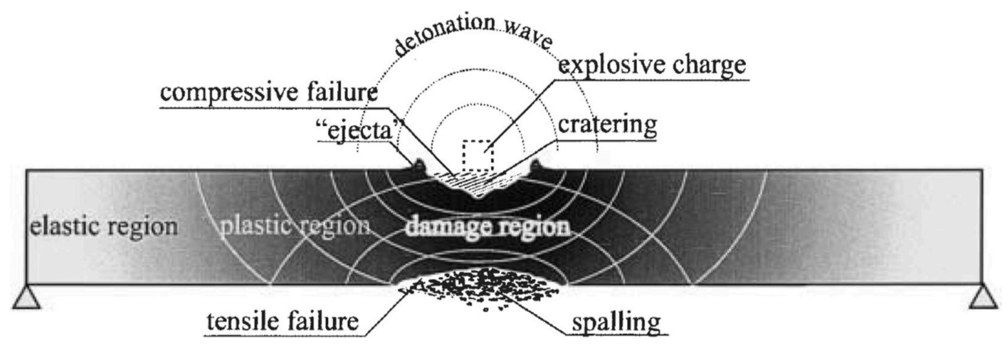
Damage to RC structures from blast loads can be understood using the detonation scaled distance factor [1,45]. In cases of contact or very near explosions, concrete elements often show spalling on the back face (tensile zone) [1,3,45]. On the front side (compression side), the blast wave strikes the surface with high intensity, leading to compressive failure, small craters, and the breaking away of crushed concrete fragments (ejecta), as shown in Figure 8 [1]. This occurs due to tensile stresses that develop when blast waves propagate through the concrete and reflect from structural boundaries, rather than from suction effects. A clear damage zone forms between the compression area and the spalled remote surface. This region shows micro-cracking, crack widening, and gradual stiffness degradation.
Flexural failure in RC columns is commonly classified using the displacement-ductility ratio, following McVay’s (1988) [47] approach. A summary of this classification is presented in Table 3 [1,45].
A lot of research has been carried out on how RC members behave under blast loading [1,2,3,38,39,40,41,42]. Studies on beams [48,49,50,51,52,53,54], columns [2], and slabs [55] have helped understand how damage develops under such impacts. Beyond individual members, there is also considerable work on how larger structures, like framed buildings [56,57] and bridges [58,59,60,61], respond to blast loads.
Table 4 presents the typical failure patterns seen in different RC members under varying blast conditions [2]. For columns, severe spalling was reported in case (A) for contact and very near blasts [62], while case (B) showed a combination of local and overall failure under near blasts [63]. Widespread flexural damage appeared in case (C) during far-field blasts [64]. Cases (D) and (E) for columns were reported by [58], and [62], respectively. For beams, cases (F), (G), and (H) were observed in studies by [49,53,54]. Slab failures, represented by cases (I), (J), and (K), were documented by [65,66,67].

2. Novelty of This State-of-the-Art Review

In this state-of-the-art review, the authors take a different approach by comparing and combining past studies rather than just summarizing them. Experimental, numerical, and analytical works are brought together to show clear differences across column shapes, reinforcement details, material grades, and standoff distances of explosions. This makes it easy to understand why advanced materials like UHPC, FRP wrapping, or steel-concrete composites perform better and how much they improve strength, displacement control, or energy absorption. This review also highlights emerging machine learning (ML) models for predicting blast response, a topic often missed in earlier studies. Comparing experiments with FE and SDOF predictions, the authors point out gaps in current design codes, especially in handling near-field effects, local damage, and progressive collapse caused by explosions.
A review of over 40 specific studies on RC column response under blast loading shows that this area of research is still at an early stage. Most studies are scattered with little effort to combine material innovations, geometric effects, and predictive models into comprehensive design guidance. Columns require special focus as their sudden failure can lead to progressive collapse, making them particularly crucial than beams or slabs for overall structural safety. However, most current design codes and guidelines are based on simplified assumptions and far-field approximations. This leaves significant uncertainties when dealing with close-range blasts, localized damage, and realistic retrofitting solutions. Therefore, this review aims to bring together these fragmented findings, offering a comparative perspective and pointing out key directions for future research and updates to design codes.
Although the central focus is on RC columns, composite and concrete-filled steel tubular (CFST/CFDST) columns are also discussed where appropriate. Including these types is important, as they follow similar load-transfer behavior and are being increasingly used in protective structures due to their better confinement and ductile response under blast loading.
This state-of-the-art review is organized as follows. Section 1 covers the background, basics of blast loading, and failure modes of RC members. Section 2 discusses novelty and organization of this review. Section 3 brings together analytical, numerical, and experimental studies, arranged based on the shape of the columns. It begins with square columns, which are further divided into subtopics such as the effects of axial load, material types, reinforcement detailing, strengthening or retrofitting methods, modeling techniques, and a comparison between the experimental and simulation results. Following this, studies on rectangular columns are presented, and finally, circular columns are discussed along with their respective subcategories. Section 4 looks at how studies have developed over time. Research has gradually moved from basic small-scale experiments to detailed numerical simulations. More recently, approaches that combine data-driven methods with ML and FE techniques have gained attention. Section 5 draws conclusions and highlights the main design points for square, rectangular, and circular RC columns under blast loading. The findings are also presented in the form of tables. Section 6 looks at potential directions for future research, while Section 7 points out remaining gaps and open issues in the field.

3. RC Columns Under Blast Loading

Understanding the effects of explosive shock waves on structures has become increasingly important due to the rising incidents of accidental and intentional explosions [1,2,3]. Structural damage from blasts can vary widely, from minor repairable cracks to complete collapse with severe loss of life [23]. A notable example is the 1968 Ronan Point gas explosion, a 22-storey tower in East London, which caused progressive collapse due to severe damage to structural members [68]. In recent years, civilian buildings such as schools, universities, hospitals, and embassies have been frequent targets of blasts [46]. Since most of these buildings are made of RC, a thorough study of their behavior under extreme loading conditions is essential.
RC exhibits highly complex responses under blast loading [1]. Blast loads act over very short durations, creating localized zones of extremely high pressure and stress [45]. The shock wave travels through concrete as a compressive wave and, upon reflecting from a free surface, converts into a high-tensile wave, often causing spallation of the concrete surface [45]. Structural responses vary depending on the type of detonation [1]. Contact explosions typically produce spalling and crater formation, whereas close-in detonations generate flexural or flexure-shear damage [1].
Columns, being the primary load-bearing members in framed structures, are especially critical. Sudden failure of a column due to material loss can trigger a chain reaction of progressive collapse [69]. Historical events highlight the devastating consequences of such failures. For instance, during the 1993 World Trade Center attack, floor slabs failed but the robust columns prevented complete collapse at that time [70]. The 1995 Oklahoma City bombing caused partial collapse of the Alfred P. Murrah building, resulting in 168 deaths [71]. In 1999, attacks on residential buildings in Russia claimed 293 lives and caused extensive structural damage [69]. These examples underscore the need for robust blast-resistant design of structural columns. Damage from contact explosions is significantly more severe than from close-in or near-field blasts [69,72]. Ground floor columns are particularly vulnerable and must be designed with sufficient strength, ductility, and continuous lateral reinforcement to prevent progressive collapse [2]. Under contact detonations, the blast wave directly couples with the column surface, generating extremely high strain-rate stresses, localized pulverization of concrete, and severe scabbing or penetration. Such localized impulsive loading can instantaneously degrade axial load-carrying capacity and initiate shear plug or punching failures, well before the member can mobilize its flexural or global resistance mechanisms.
Axially loaded RC columns in low- and medium-rise buildings are often exposed to potential blast hazards in public areas [2]. Due to their low redundancy compared to beams or slabs, evaluating the blast response, residual capacity, and vulnerability of columns is vital for reducing casualties and limiting structural damage. Columns not only carry gravity loads but also transfer lateral forces to the foundation [3,23,73]. Under extreme blast loads, a single column failure can become a local hazard, potentially triggering disproportionate or progressive collapse [3]. Both accidental and intentional explosions can lead to significant human and economic losses, highlighting the importance of blast-resistant column design. Consequently, a majority of studies focus on understanding RC column behavior under blasts through analytical, numerical, and experimental investigations [2,3,4,23,40,52,56,58].

3.1. Studies on Square Columns

  • Effect of Axial Load and Boundary Conditions
Research on square columns has consistently highlighted the critical role of axial load and boundary conditions in blast response. Astarlioglu et al. [74] carried out numerical investigations on RC columns of 406 × 406 mm cross-section and 3660 mm length under combined axial and blast loading using DSAS and ABAQUS. Their work showed that axial load below the balanced value improved flexural resistance, but beyond this limit both strength and ductility dropped. Fixed boundary conditions contributed additional reserve strength through tension membrane action, though high axial forces combined with strong blasts led to shear failures.
Similar observations came from the later work of Astarlioglu and Krauthammer [75], who compared ultra-high performance fiber reinforced concrete (UHPFRC) columns with normal strength concrete (NSC). Columns reinforced with steel fibers displayed smaller displacements, 27% lower under simply supported and 30% lower under fixed ends, indicating the combined effect of material strength and boundary conditions. UHPFRC columns also withstood over four times the impulse sustained by NSC columns.
Experimental studies by Xu et al. [76] further established how axial loads modify column performance under blast. Field tests on 200 × 200 mm UHPFRC columns with 1000 kN axial load revealed that these columns resisted higher peak overpressures with reduced residual displacements compared to high-strength RC. Damage patterns included spalling and flexure–shear failures, but UHPFRC demonstrated better confinement and energy absorption. Zhang et al. [77] expanded this discussion through blast tests on concrete-filled double-skin tubular (CFDST) columns. With axial loads of 1000 kN, these specimens resisted peak overpressures up to 30 MPa without tube buckling. The applied axial load acted like a pre-stress, lowering transverse deflections. Parametric studies confirmed that displacement reduced when axial load ratio (ALR) remained below 0.60, and thicker outer steel tubes contributed more to stiffness.
Chen et al. [78] provided additional clarity through extensive field blast experiments on 200 × 200 mm RC columns, where ALR ranged between 0 and 0.30. At higher ALR, blast resistance improved for scaled distances greater than 0.40 m/kg1/3, while at lower scaled distances, crushing and shear damage dominated. Cylindrical double-end charges caused more severe failure than spherical charges of equal weight, showing that boundary and initiation conditions strongly affect response.
Recent simulation studies have also supported these findings. Kim et al. [79] examined 81 RC columns under different scaled distances and reinforcement ratios. The results showed that while higher longitudinal reinforcement reduced ductility demand, transverse reinforcement enhanced ductility and limited residual damage. ALR had little effect on residual strength but increased ductility demand due to P-Δ effects. The authors stressed the need for performance criteria combining both displacement and residual strength.
Studies on eccentric blasts under axial compression show that localized boundary effects and excessive axial loads can alter failure modes. Shen et al. [80] combined scaled field experiments and FE models to study eccentric blasts with axial compression. Columns under axial compression showed reduced midspan displacement, but excessive axial load led to premature crushing. Boundary effects were visible in eccentric blasts where base shear failures reduced residual strength. Parametric studies confirmed that larger section size and higher reinforcement ratios helped reduce displacements significantly.
Critical Discussion: This section presents a detailed critical discussion that brings together and interprets findings from earlier studies on the combined effect of axial load and boundary conditions. As suggested by the reviewer, the emphasis here is on developing a coherent interpretation of the overall trends and insights, rather than repeating the descriptive details already discussed in the previous sections.
A review of past studies shows that the effect of axial load and boundary restraint on the blast behavior of RC and composite columns is quite complex and closely connected. Some researchers, including Astarlioglu et al. [74] and Xu et al. [76], observed that a moderate level of axial compression improves flexural stiffness and energy absorption. However, when the axial load becomes too high, it leads to crushing and shear-type failures, as noted by Chen et al. [78] and Shen et al. [80]. This clearly indicates that the positive effect of axial compression exists only up to a certain limit, beyond which instability and local crushing dominate.
Boundary conditions further influence this behavior. Fixed or clamped supports, as reported by Astarlioglu and Krauthammer [75], enhance the overall capacity through membrane action, but they can also shift the failure mode from bending to shear or base-shear when the blast intensity is high. The type of material and detailing also play a major role. Columns made with UHPFRC and CFDST [75,76,77] showed better confinement and could withstand higher impulses with smaller displacements, while normal RC columns often showed spalling and flexure-shear cracks.
Reinforcement detailing proved equally important. Kim et al. [79] found that increasing transverse reinforcement helps control damage and improves ductility, even when axial loads increase the P-Δ effects. Similarly, Zhang et al. [77] showed that optimizing the axial load ratio (below 0.60) and steel tube thickness can enhance stiffness, showing the combined benefit of pre-stress and confinement.
Collectively, these findings highlight that the blast resistance of columns cannot be attributed to axial load or boundary conditions in isolation. Instead, their combined influence, moderated by reinforcement detailing, confinement, and material composition, dictates the overall response. Future research should therefore focus on realistic end-restraints, eccentric loads, and practical load ratios to ensure that design approaches address both strength improvement and failure prevention within safe operational limits.
  • Influence of Concrete Type and Material Properties
Several studies have highlighted how concrete type, reinforcement ratio, fiber content, and detailing influence the blast performance of square columns.
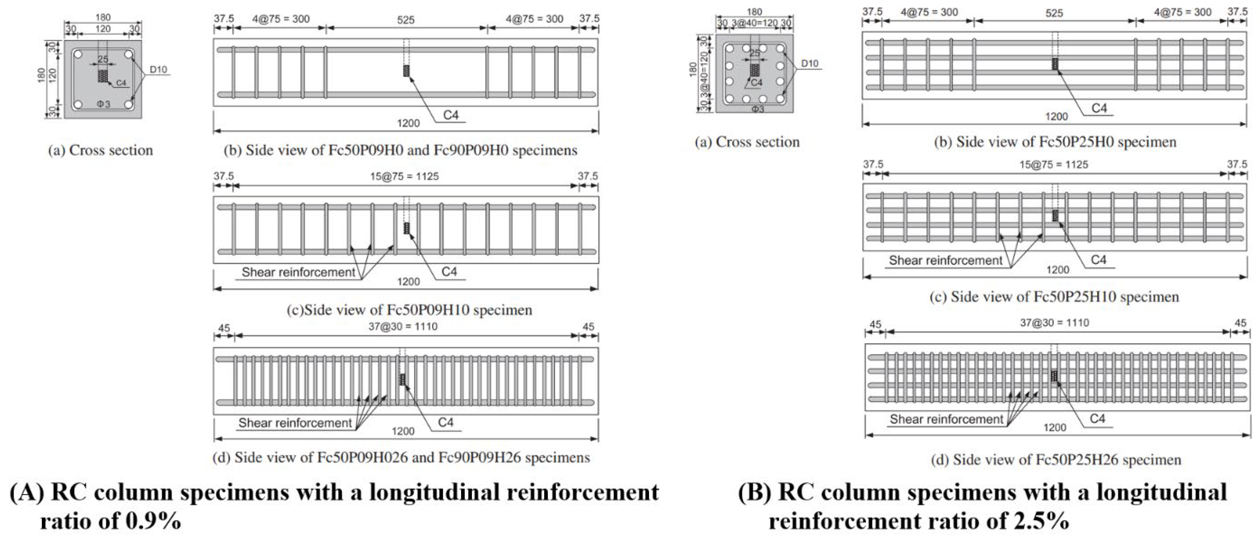
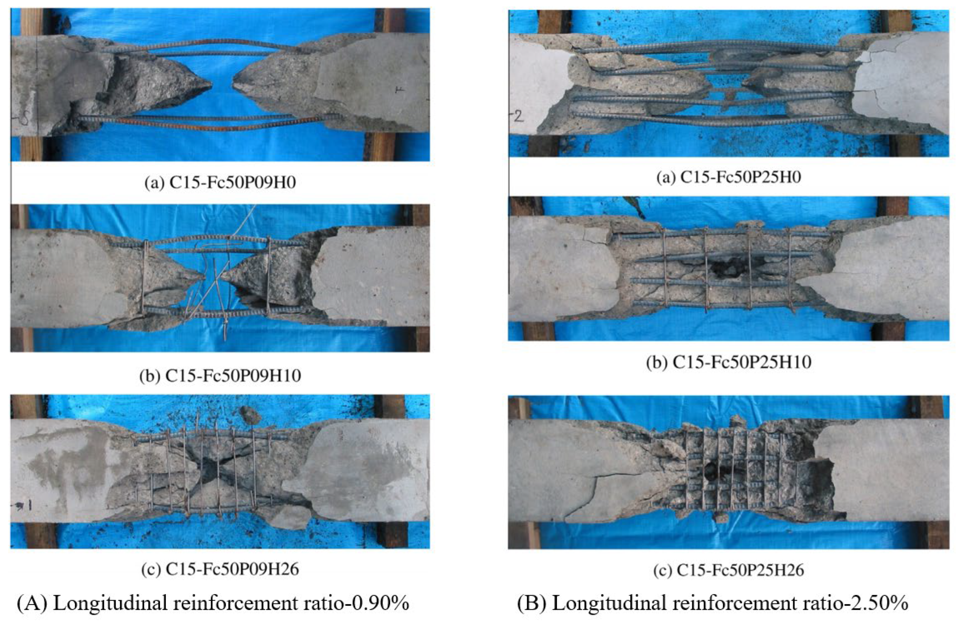
Fujikake and Aemlaor (2013) [73] tested fourteen freestanding RC columns of 180 × 180 mm section and 1200 mm length under contact detonations with small charges. Columns were cast using normal concrete (51.60 MPa) and high-strength concrete (90.30 MPa). The results showed that both compressive strength and reinforcement ratio significantly affect column behavior under blasts. Columns with higher longitudinal reinforcement (2.5%) resisted damage better than those with 0.9% reinforcement, even when shear reinforcement was kept constant (Figure 9 and Figure 10, as reported in Fujikake and Aemlaor (2013) [73]). In Figure 10, the columns with a low longitudinal reinforcement ratio (0.90%) showed heavy damage. They developed wide cracks, bar buckling, and splitting failures, which pointed to weak confinement. On the other hand, columns with a higher reinforcement ratio (2.50%) performed much better. Damage was limited to small areas, with reduced spalling and crashing mainly around the mid-height, even though the shear reinforcement was the same. Closely spaced transverse reinforcement also played a strong role by controlling crack width and preventing bar buckling, which helped the columns remain stable under blast loading.
Composite columns are also reviewed in this subsection to illustrate how steel confinement alters blast response compared with plain RC columns. Their behavior provides useful insight into emerging hybrid design approaches
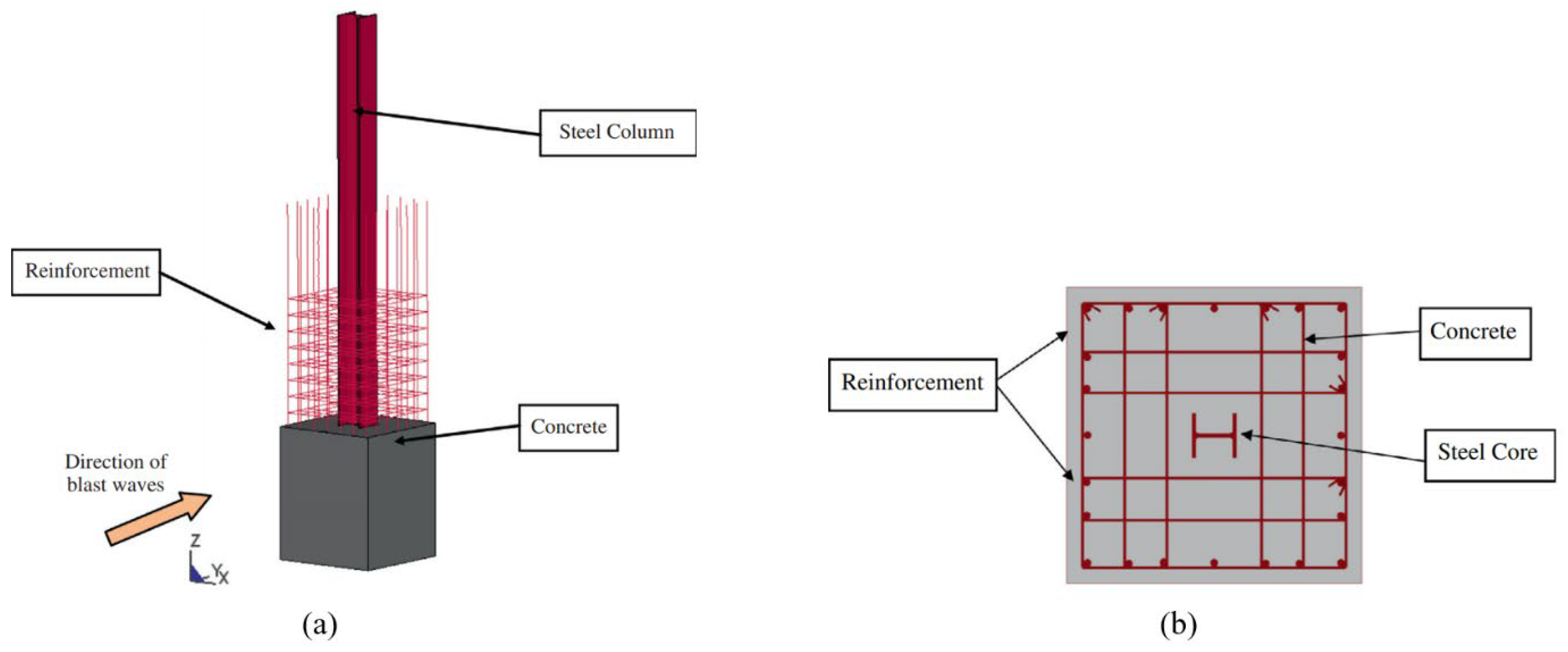
To study how different materials improve blast resistance, Jayasooriya et al. (2014) [56] carried out a comparison between concrete-steel composite (CSC) columns and RC columns using LS-DYNA simulations (Figure 11 [56]). The CSC columns were designed in accordance with the Australian Standard Code of Practice for Concrete Structures (AS 3600 [81]). Each column measured 4700 mm in length with a cross-section of 1000 mm × 1000 mm, incorporating a centrally placed 250 UC 72.9 steel core. The CSC columns, built with a central steel core and 48 MPa concrete, retained higher residual load capacity under TNT blasts compared to equivalent RC columns. The analysis considered charge weights ranging from 50 kg to 500 kg of TNT with scaled distances between 0.63 m/kg1/3 and 1.36 m/kg1/3. The focus was mainly on the positive phase of the blast pressure. Performance improvements were more visible at lower axial loads (25%), where CSC columns showed reduced displacement and better cracking control. However, under higher axial loads (50% and 75%) and larger charge weights (>400 kg), the CSC columns exhibited failure, while RC columns failed even earlier under similar blast intensities.
Aoude et al. (2015) [36] investigated UHPFRC columns reinforced with different fiber contents and bar ratios. Columns with higher steel ratios or closely spaced hoops performed better. Fiber addition improved blast resistance up to 4%, beyond which displacement increased, sometimes causing rupture of longitudinal bars. Their results were consistent with SDOF predictions. Similarly, Burrell et al. (2015) [82] compared SFRC and SCC columns under shock-tube blasts (Figure 12 [82]). SFRC columns, especially with seismic detailing, showed better control of displacement and cracking. However, fiber addition in non-seismic columns did not fully prevent rebar buckling.
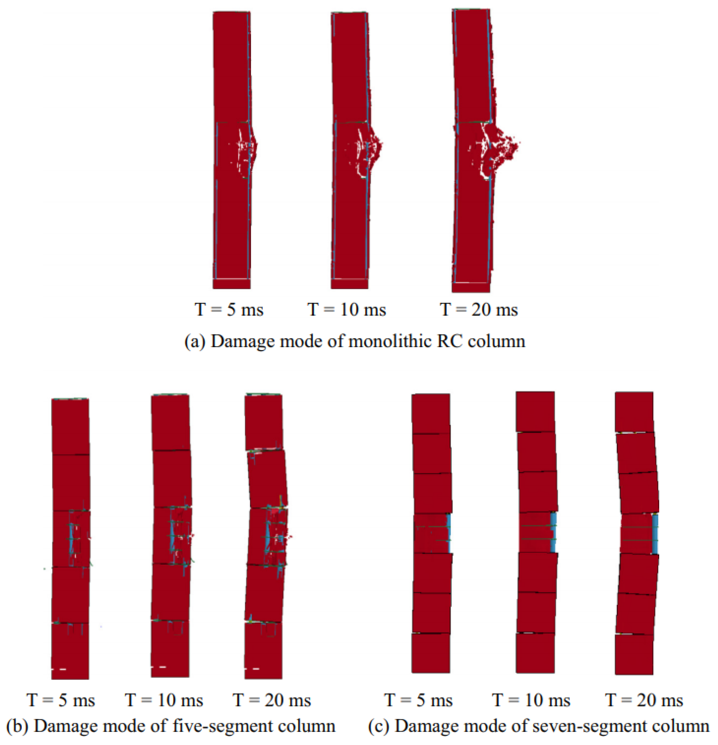
Advanced construction techniques and the use of high-performance concrete have shown encouraging results in recent projects. Li et al. (2017) [83] studied segmental RC columns and found that segmental construction with shear keys improved blast resistance by dissipating energy through slippage and opening of segments (Figure 13 and Figure 14 [83]). Another work by Li et al. (2017) [84] tested UHPC columns reinforced with micro and twisted steel fibers under close-in blasts. Columns with micro steel fibers retained over 70% of their capacity even after a 35 kg TNT blast, while high-strength RC (HSRC) columns retained only 40% after much smaller blasts. The study highlighted the superior role of microfibers in absorbing blast energy.
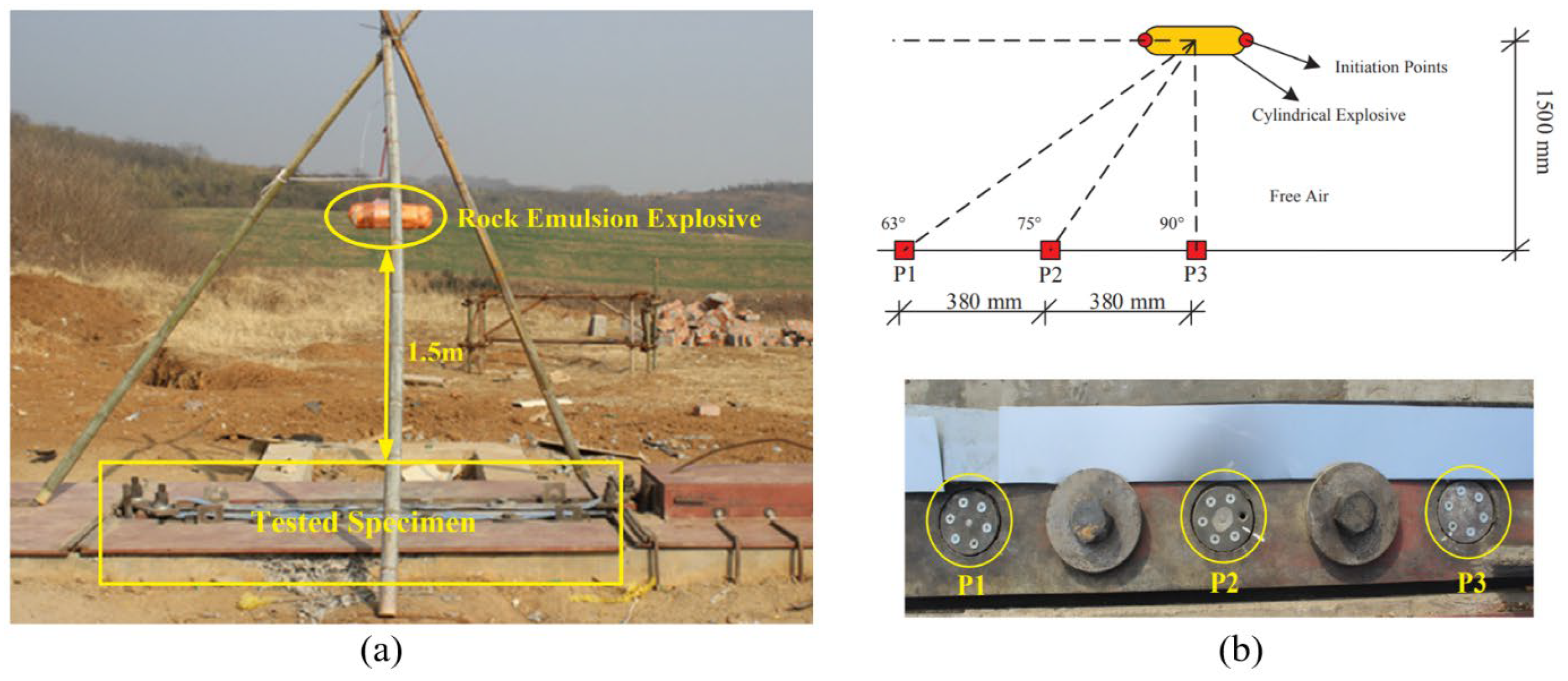
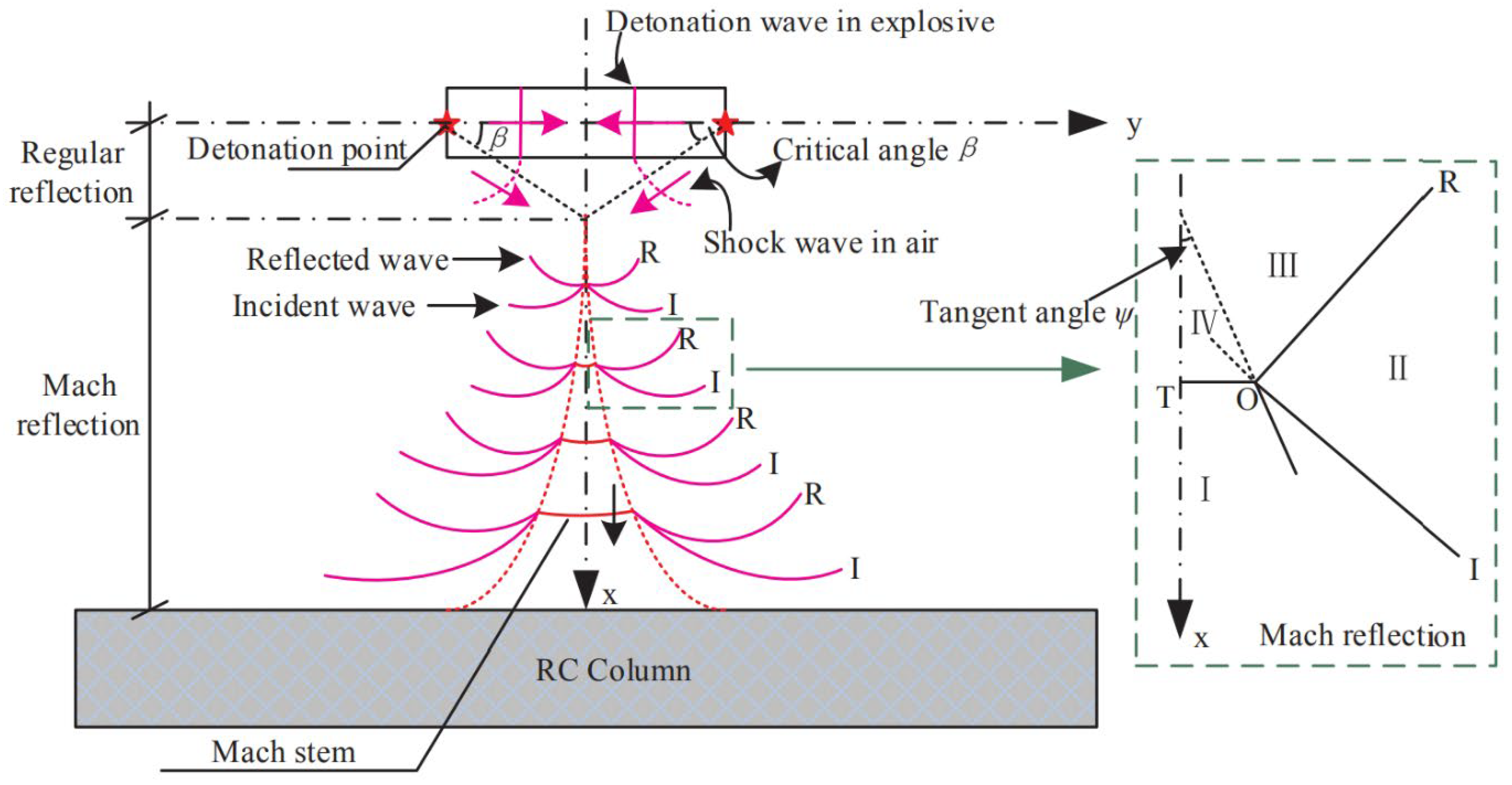
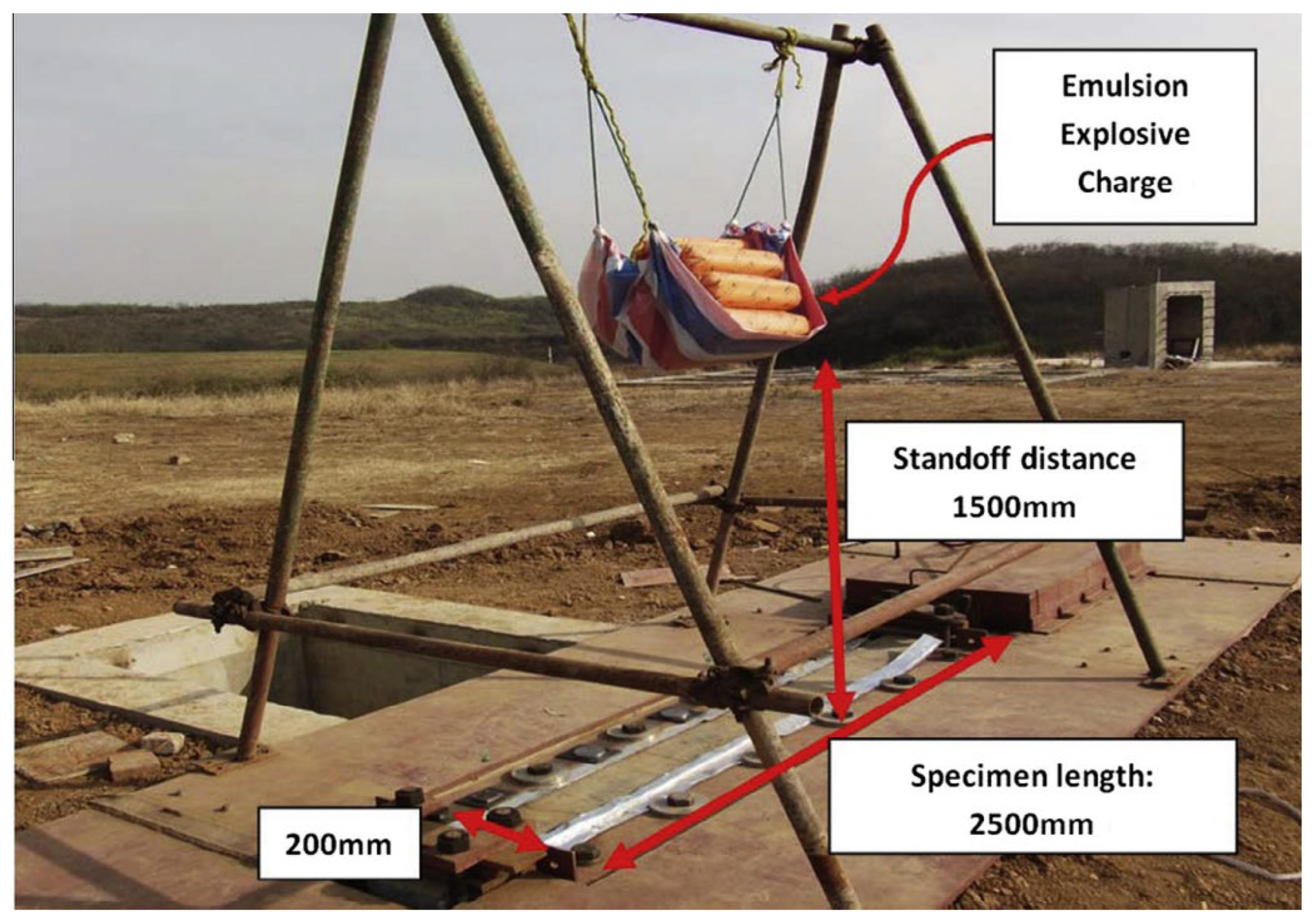
In addition to material and structural parameters, the nature of the explosive and its configuration can substantially influence column response. Hu et al. (2018) [85] explored how explosive geometry and charge configuration affect RC columns. In this setup [85], cylindrical rock emulsion explosives were kept 1.5 m above the specimens being tested, with several initiation points ensuring a symmetric detonation (Figure 15 and Figure 16 [85]). Pressure gauges placed at angles of 63°, 75°, and 90° recorded the variation in blast intensity across different positions. Tests showed that cylindrical double-end charges produced much higher pressures than spherical charges due to self-Mach reflection effects. This highlighted how explosive setup itself can drastically change the damage mechanism. The wave interaction diagram (Figure 17 [85]) explains how incident and reflected waves meet to create Mach stems. The critical angle β and tangent angle ψ determine when self-Mach reflection begins, which in turn increases the blast load on the RC columns.
The influence of reinforcement detailing under demolition-scale blasts was later studied by Yan et al. (2022) [86], who tested RC columns (200 × 200 mm, 1200 mm height) with varying reinforcement levels. They reported that increasing longitudinal bar diameter reduced deflections, while stirrup size and spacing had a stronger influence on confinement and crack control. Even so, the actual energy absorbed by the columns remained low, with only about 2% of explosive energy effectively used. Their equations for predicting damage zones and deflection emphasized the importance of shear reinforcement in blast resistance.
Extending this line of investigation, Zhang and Niu (2025) [87] performed experiments on the blast response of different concrete columns: conventional RC, reinforced coral aggregate concrete (RCAC), and fiber-reinforced coral aggregate concrete with steel bars (RFRCAC). Columns were 200 × 200 mm in cross-section and 1800 mm tall, reinforced with 12 mm longitudinal bars and 8 mm stirrups, with 25 mm cover. The 28-day compressive strengths measured 47.85 MPa for RC, 46.05 MPa for RCAC, and 55.18 MPa for RFRCAC. Field blast tests used 2 kg TNT charges at scaled distances of 0.317, 0.556, and 0.794 m/kg1/3, under fixed-end conditions, with and without an axial load of 152.8 kN (ALR = 0.2). The results showed RFRCAC performed best under blast. At the closest distance (Z = 0.317 m/kg1/3), spalling on the blast side dropped by 37.25% compared to RC and 45.76% compared to RCAC, while back-face spalling reduced by 13.85% compared to RC. Peak reflected pressure reached 0.62 MPa at 2 m, decreasing by 39.35% as scaled distance increased. Displacements indicated faster peak response for RC (6.74 ms) than RCAC (7.15 ms) and RFRCAC (7.63 ms). Peak quarter-span displacements fell with distance, from 14.43 mm to 3.03 mm for RC, 17.69 mm to 3.59 mm for RCAC, and 12.21 mm to 2.85 mm for RFRCAC. The study concluded that using coral aggregate alone reduced blast resistance. Adding fibers (basalt + polypropylene) greatly improved crack control, reduced displacements, and enhanced energy dissipation. RFRCAC emerged as a promising material for protective structures on islands or reefs.
Critical Discussion:
A close look at these studies [56,73,82,83,84,85,86,87] shows that both the type of material and the detailing play a crucial role in blast performance. Fujikake and Aemlaor [73] observed improvements linked to concrete strength, while Jayasooriya et al. [56] reported that CSC columns maintained higher residual capacity, particularly under lower axial loads. Burrell et al. [82] noted that increasing fiber content beyond roughly 4% gave limited benefits due to bar rupture. Similarly, Aoude et al. [36] highlighted how fiber content and bar ratios affect displacement and cracking. Li et al. [83,84] found that UHPC and segmental RC with shear keys offer superior residual capacity, but Hu et al. [85] pointed out that charge geometry can reduce these material advantages. Recent work by Yan et al. [86] stressed that longitudinal and transverse reinforcement strongly influence confinement and crack control. Zhang and Niu [87] demonstrated that fiber-reinforced coral aggregate concrete effectively reduces spalling and improves energy dissipation. This indicates that, although high-strength and fiber-reinforced concretes enhance energy absorption, their real performance depends on factors like fiber orientation, confinement, and the specifics of the blast scenario.
  • Reinforcement Detailing & Seismic Provisions
The role of reinforcement detailing and seismic provisions in improving the blast performance of square RC columns has been widely studied. A number of investigations [2,23,88] have shown that proper reinforcement layout, stirrup spacing, and seismic ties greatly influence the displacement response, crack control, and overall resistance of columns under explosive loads.
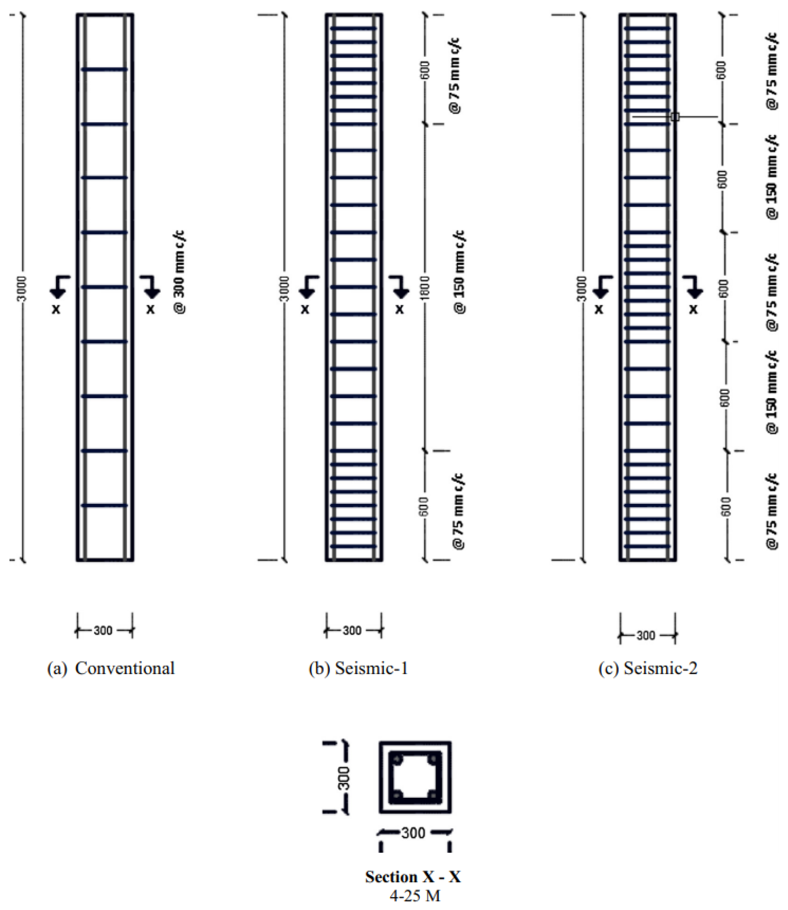
To experimentally evaluate the benefits of seismic detailing, Kyei and Braimah [2] performed large-scale blast experiments on 3000 mm long RC columns with 300 × 300 mm cross-section under axial load. Conventional detailing and two seismic layouts were compared (Figure 18a–c [2]). Reinforcements were placed as per the guidelines of CSA A23.3 [89]. In the closest blast scenario (scaled distance 0.80 m/kg1/3), the conventional column recorded 553 mm lateral displacement, while Seismic-1 and Seismic-2 reduced it to 319 mm and 316 mm, respectively. The Seismic-2 layout, with reinforcement at the top, bottom, and mid-height, showed the best control over cracking and displacement. LS-DYNA predictions closely matched experimental observations. Numerical studies further confirmed that reduced stirrup spacing improved performance at small scaled distances, while higher ALRs led to crushing and bar buckling.
Rajkumar et al. [23] extended this line of work through FE simulations on 900 mm long square columns (85 × 85 mm) reinforced with eight longitudinal bars and stirrups at 60 mm center-to-center (c/c) (Figure 19 [23]). Additional open ties were also provided. Under a 7.10 kg Composite-4 blast charge, seismic detailing improved resistance when compared to conventional layouts. Among different shapes with equivalent volume, circular columns showed lower peak deflections. The study emphasized that higher reinforcement ratio and seismic ties both enhanced blast resistance.
Wu et al. [88] presented a detailed parametric study using ANSYS/LS-DYNA 2020R2, validated against tests on 1700 mm × 150 mm × 150 mm RC columns reinforced with four longitudinal bars and stirrups at 210 mm spacing. Under a 0.4 kg TNT charge at 0.5 m (scaled distance 0.68 m/kg1/3), the experimental and simulation results were in close agreement. Parametric analysis showed that reducing stirrup spacing, increasing bar diameter, and providing more longitudinal bars sharply reduced displacements. For instance, increasing bar number from 4 to 16 reduced displacement from 23.76 mm to 1.18 mm. Grey relation analysis ranked stirrup spacing (0.6914) as the most influential factor, followed by stirrup diameter, scaled distance, and bar properties. The findings confirmed that reinforcement detailing has greater impact on blast resistance than just increasing concrete strength.
Critical Discussion:
Experimental and numerical studies [2,23,88] consistently show that proper reinforcement detailing and seismic provisions play a key role in controlling displacement and cracking in RC columns under blast loading. Kyei and Braimah [2] reported that seismic layouts with well-distributed reinforcement at the top, bottom, and mid-height reduced lateral displacement by over 40% compared to conventional detailing. Similarly, Rajkumar et al. [23] found that adding extra ties and increasing reinforcement ratios significantly improved resistance, especially in circular columns. Wu et al. [88] emphasized that stirrup spacing is critical, with closer spacing and more longitudinal bars reducing displacement by more than 90%.
From a mechanical perspective, seismic detailing enhances column performance by confining the concrete core, which delays cracking and crushing, improves ductility, and prevents longitudinal bars from buckling under high lateral loads. Closely spaced stirrups restrict outward concrete expansion, maintain the alignment of main reinforcement, and distribute stresses more evenly along the column height. Additional ties or hoops help dissipate energy through controlled yielding and plastic hinge formation, allowing the column to deform without sudden failure. Differences observed across various studies are largely due to variations in scaled distance, axial load ratio, and column geometry. Overall, dense stirrups, carefully chosen bar diameters, and seismic detailing improve ductility and blast resistance more effectively than simply increasing concrete strength. This demonstrates the importance of seismic or confining reinforcement design in mitigating extreme blast effects.
  • Strengthening/Retrofitting Techniques
Several investigations have focused on enhancing the blast performance of square RC columns using various strengthening or retrofitting approaches.
To improve blast resilience, Alsendi and Eamon [90] conducted a detailed numerical study on a 5000 mm tall RC bridge pier with a 900 × 900 mm cross-section. Strengthening was achieved using a steel fiber reinforced polymer (SFRP) composite wrap. LS-DYNA software was employed for simulations, considering parameters such as concrete strength (28 MPa and 55 MPa), steel reinforcement ratio (0.029 and 0.042), and gravity loads. The baseline column used 42 MPa concrete and 24 longitudinal steel bars of 25 mm diameter (grade 60, yield strength 420 MPa). Transverse confinement consisted of 13 mm stirrups spaced at 300 mm with open ties in both directions, and a 50 mm concrete cover. The SFRP wrap had a thickness of 1.2 mm, a yield strength of 985 MPa, and Young’s modulus of 66.10 GPa. Concrete behavior was modeled using the Johnson-Holmquist-Cook (JHC) approach. Boundary conditions assumed the column base to be fixed while the top was hinged. Only the positive phase of the blast was considered, using the CONWEP empirical blast model proposed by Kingery and Bulmash (1984) [22] and defined in Equation (3) [90].
P t = P o 1 ( t t a ) t d e b ( t t a ) t d
P t = blast pressure at time “t” (MPa), ta = the time of blast wave arrival (sec), td = duration of positive blast phase (sec), and b = decay coefficient. The total air-blast pressure, PT(t), was defined by Equation (4) [90]:
P T t = P r t   c o s 2 θ +   P s o t   ( 1 + c o s 2 θ 2 cos θ )   For   c o s θ 0
P r t = reflected blast pressure at time “t” (MPa), P s o t = side-on or incident blast pressure at time “t” from Equation (3) such that P s o t = P ( t ) , and θ = angle of incidence.
Results showed that doubling concrete strength increased blast resistance by 1.5 times, while raising reinforcement by 3.5 times improved capacity by 1.2 times under a peak overpressure of 11.2 MPa [90]. Wrapping the lower half with SFRP increased capacity by 10–15%, while adding an extra layer offered no significant gain.
To evaluate practical retrofitting in building columns, Pathak et al. [91] investigated corner and edge RC columns of buildings designed as per ASCE/SEI 7-16 [92] and ACI 318-14 [93]. Both low and high seismic zones were considered. Columns were retrofitted with fiber-reinforced polymer (FRP) jackets and subjected to close-in blasts using LS-DYNA. Concrete was modeled using the MAT072R3 damage model (density 2400 kg/m3, compressive strength 68.94 MPa, tensile strength 6 MPa, Poisson’s ratio 0.20). For low seismic regions, corner columns had 12 steel bars of 10 mm diameter, and edge columns had 16-#11 + 4-#14 bars. In high seismic areas, corner columns had 12-#11 + 8-#10 bars, while edge columns had 28-#10 bars. Cross-sections measured 914.4 × 914.4 mm for low seismic and 1219.2 × 1219.2 mm for high seismic zones. Transverse reinforcement consisted of single master ties and open ties, spaced 100 mm near the top/bottom and 300 mm along mid-height. Steel had a yield strength of 410 MPa and ultimate tensile strength of 510 MPa. Numerical simulations indicated that FRP-retrofitted columns performed better than non-retrofitted ones, showing higher resistance to shear stress and lower effective plastic strain.
Focusing on explosive-load scenarios, Yan et al. [94] performed explosion tests on 1700 mm long RC columns of 150 × 150 mm cross-section. Columns were strengthened using woven carbon-FRP (CFRP) sheets of 2 mm and 4 mm thickness in different configurations. Explosive loads of 0.80 kg, 1 kg, and 1.40 kg TNT were applied at 0.40 m and 0.50 m standoff distances, resulting in 12 test combinations. Columns had four 12 mm diameter steel bars (yield strength 400 MPa, ultimate 518 MPa), with 6 mm closed hoops spaced 180 mm c/c. Concrete cover was 20 mm. Retrofitting was applied to the tension face or both faces using various CFRP arrangements. Tests revealed that CFRP on the tension face significantly improved blast resistance, enhancing both flexural and shear capacities. Increasing CFRP thickness reduced displacements. Dual-face strengthening prevented moment-reversal failure, though failure shifted from flexure to shear. LS-DYNA predictions closely matched the experimental results.
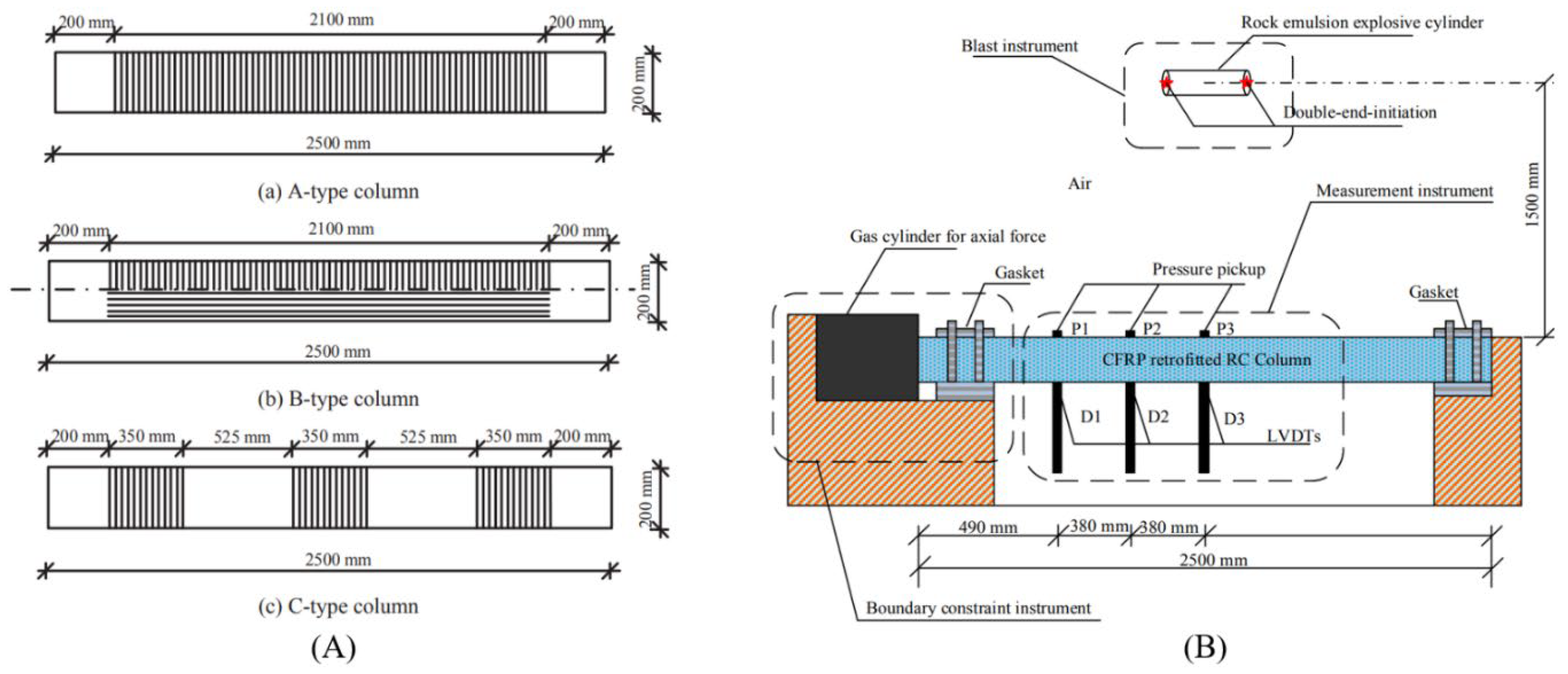
To study multi-face strengthening under high-intensity blasts, Hu et al. [95] investigated the blast performance of 2500 mm long, 200 mm × 200 mm axially loaded RC columns strengthened with CFRP strips applied on all faces in different configurations. Columns were subjected to an 18.20 kg double-end-initiation cylindrical rock emulsion explosive at a standoff distance of 1.50 m in free air, following the test setup shown in Figure 20B [95]. ALR was maintained at 0.30. Four columns were tested, including one un-strengthened control specimen (C2A3) and three retrofitted columns with different strengthening schemes: A-type with two layers of transverse CFRP strips, B-type with one layer of longitudinal plus one layer of transverse CFRP strips, and C-type with two layers of transverse segmented CFRP wraps (Figure 20, reported in [95]). Each column was reinforced with four 20 mm diameter HRB335 longitudinal bars (reinforcement ratio ρ = 3.14%). Transverse reinforcement consisted of 8 mm diameter HRB235 stirrups spaced at 150 mm c/c (ρ = 0.34%). One layer of CFRP strip had a thickness of 0.167 mm. Longitudinal bars had yield and ultimate strengths of 466.7 MPa and 601.3 MPa, respectively, while transverse steel had 483.5 MPa yield and 582.4 MPa ultimate strength. The concrete exhibited an average 28-day compressive strength of 50.16 MPa, and the CFRP had an ultimate tensile strength of 4100 MPa with a strain of 1.74%.
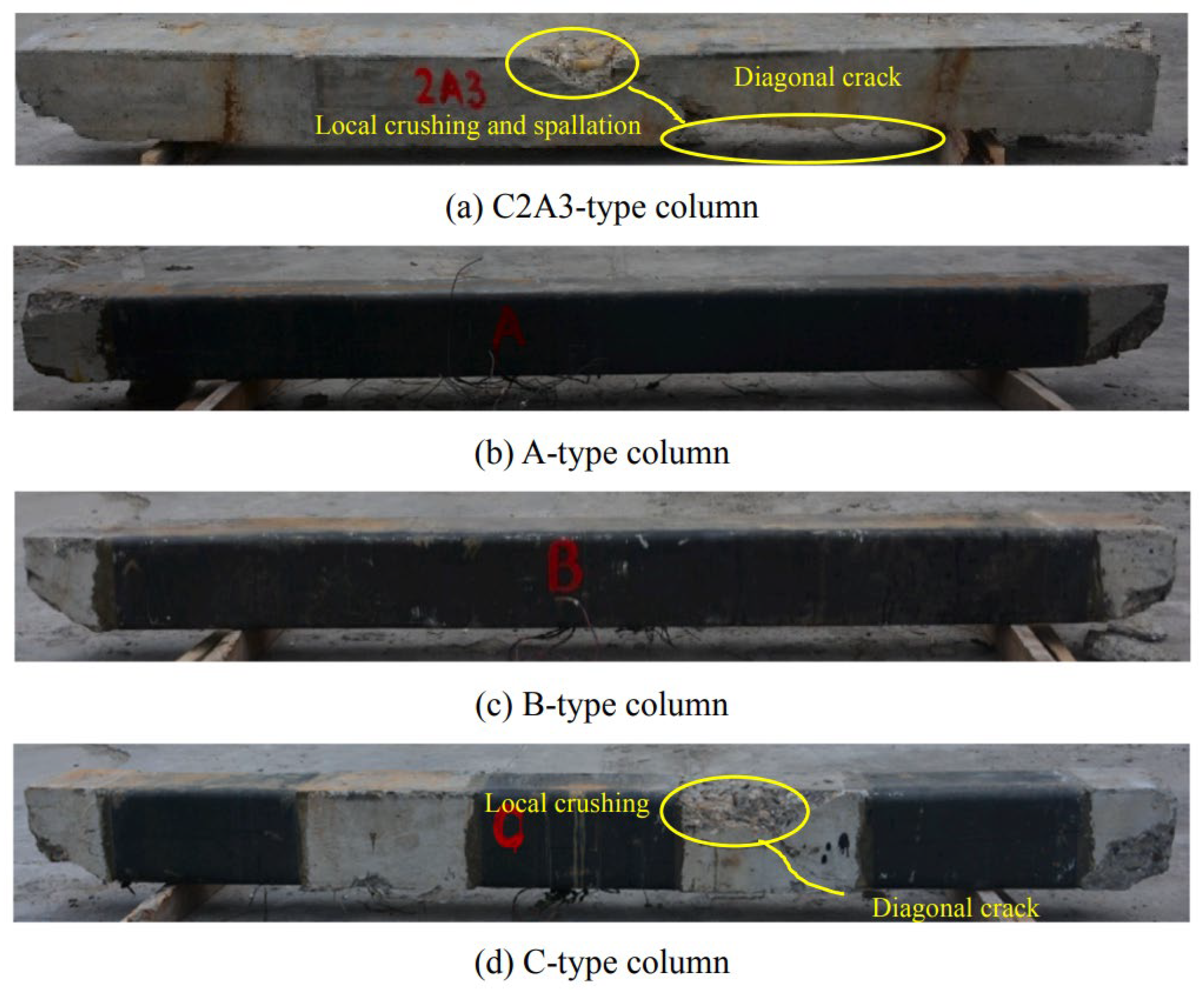
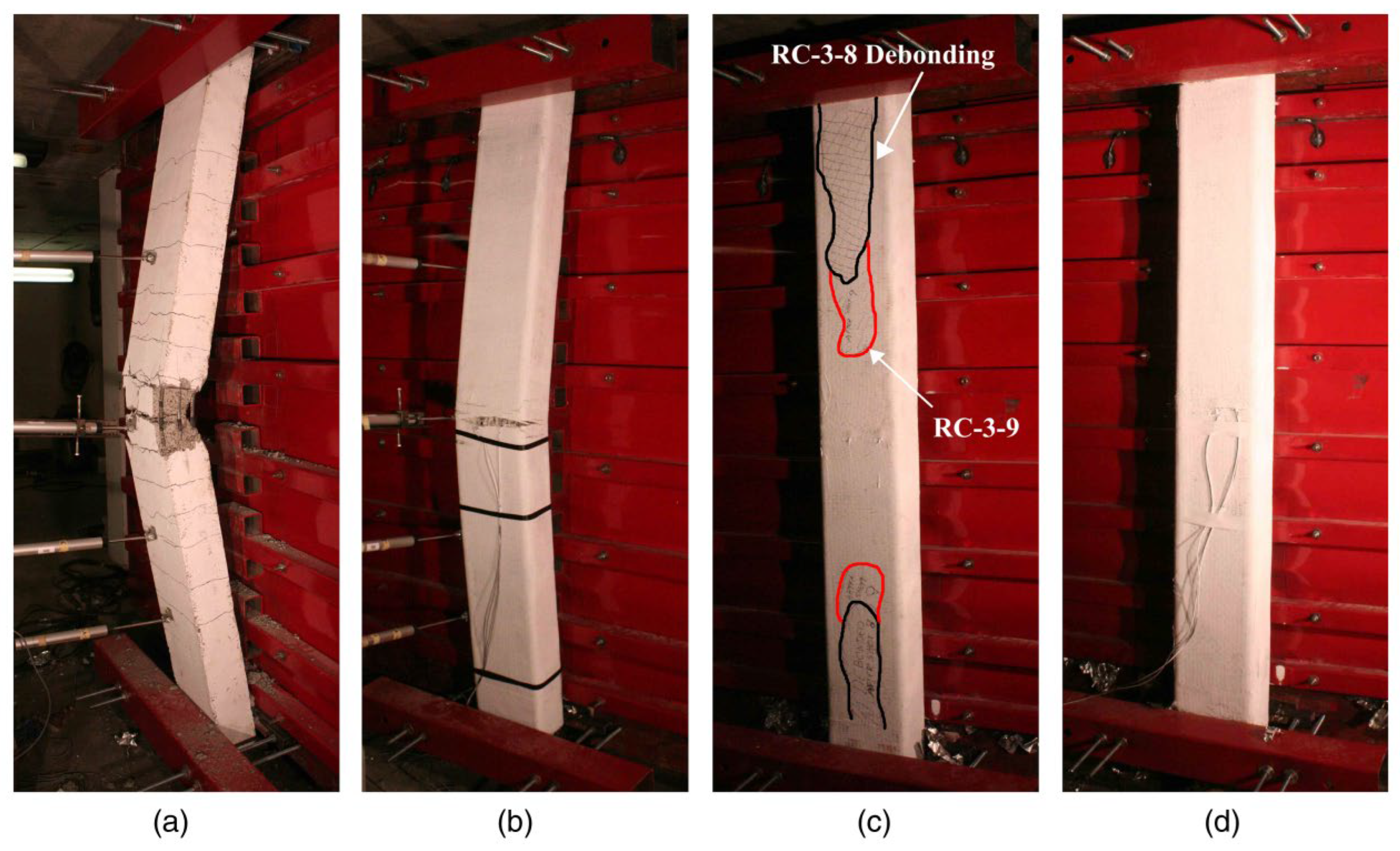
Observations showed concrete crushing at the constrained support ends (Figure 21, reported in [95]). The un-retrofitted column experienced concrete crushing on the blast face and spalling on the rear, accompanied by diagonal shear cracks (Figure 21a). Retrofitted columns of A-type and B-type showed reduced cracking compared to the control column (C2A3). The C-type column, however, exhibited concrete crushing in the non-retrofitted portion (Figure 21d). The ultimate residual axial load-capacity ratios of A-, B-, and C-type columns were 1.43, 1.27, and 1.07, respectively, relative to the control column. The results correlated closely with LS-DYNA predictions, a high-fidelity physics-based simulation tool. The study concluded that applying two layers of transverse CFRP strips on all faces (A-type) significantly enhances both cracking resistance and residual load-carrying capacity under close-in blast conditions [95].
Critical Discussion:
External confinement using FRP or SFRP wraps has proven effective in improving blast resistance. It delays spalling and helps the structure retain strength after a blast. However, Pathak et al. [91] and Yan et al. [94] note that adding thickness beyond a point does not give extra benefit. Hu et al. [95] also observed that failure can shift from bending (flexure) to shear. This shows that wrap design should aim for proper strain compatibility and energy absorption rather than just adding layers.
Recent studies emphasize smarter, analytical retrofitting. The number of layers, fiber orientation, and material durability under environmental and load effects all matter. Alsendi and Eamon [90] and Hu et al. [95] show that carefully placing CFRP strips, considering stress concentrations, reinforcement ratios, and expected blast forces, optimizes residual strength without unnecessary over-strengthening. Long-term performance also requires factoring in moisture, UV exposure, and repeated loading; so, FRP retrofits remain effective under real-world conditions.
  • Numerical & Analytical Modelling Approaches
Several studies have explored the blast response and damage behavior of square RC columns using numerical and analytical methods. Cui et al. [3] executed a 2D ALE analysis in LS-DYNA to examine the failure mechanisms of a 400 mm × 400 mm column, 3600 mm long, under axial loading and close-in TNT blasts of 1–6 kg. The results indicated that damage increased with explosive charge. Low charges (1–2 kg) caused minor spalling, while higher charges (3–6 kg) led to crushing and extensive spalling. Parametric analysis further revealed that larger cross-sections, higher transverse reinforcement, tighter stirrup spacing, and thinner concrete covers enhanced blast resistance. A new damage assessment criterion was proposed for evaluating the RC column’s performance under blast [3].
D = 1.90 + 0.25   l n ( ξ ) ( ξ 0.015 )
The damage index, ξ was defined as the ratio of the residual displacement (δ) to the column depth (h), while the damage degree, D, ranged from 0 (no damage) to 1 (severe damage), as expressed in Equation (5) [3]. The proposed criterion showed good agreement with the numerical simulations and proved effective in quantifying the structural response under high-intensity blasts.
To explore the effect of segmentation and post-tensioning, Li et al. [83] investigated segmental RC columns with different post-tensioning and shear key configurations using LS-DYNA. Columns with multiple segments exhibited lower spall damage and smaller displacements compared to conventional monolithic columns. The seven-segment column with shear keys performed best under a 5 kg TNT blast at a 0.30 m standoff. Energy dissipation bars helped moderately, and increasing the number of segments improved the column’s energy absorption capacity. Figure 13a [83], Figure 13b [83], and Figure 14 [83] illustrate the configurations and blast responses.
To improve predictive accuracy, Ju and Kwak [96] developed an improved FE model using tri-linear moment-curvature relations and DIFs for flexural response combined with empirical shear stress-slip relations. Validation against RC slabs and beams under TNT blasts showed the FE model predicted mid-span displacements accurately, outperforming SDOF methods by about 20%. Further studies on 3000 × 1000 × 1000 mm columns demonstrated that axial load reduced ductility but increased shear resistance. Shorter spans failed in shear, while longer spans failed in flexure. Adding end reinforcement improved shear but enlarging the section was more effective.
Zhou et al. [97] introduced deep learning models for rapid damage prediction in RC columns. A database of over 3000 validated simulations and 218 experiments covered columns 0.15–0.40 m in width and depth and 1.7–3.3 m in height, with TNT charges from 0.115 kg to 12,000 kg. LS-DYNA simulations, validated against field tests, showed that axial compression ratio strongly influenced damage, while blast characteristics dominated the outcomes. Deep learning predictions achieved R2 = 0.984, with failure modes classified correctly in 93–94% of cases.
Yang et al. [98] developed a database of 257 cases, including 232 FE simulations and 25 experimental tests. This database was used to train and compare eight different regression models: XGBoost, K-Nearest Neighbors (KNN), AdaBoost, Random Forest (RF), CatBoost, LightGBM (LightBoost), Support Vector Machine (SVM), and a Multi-Layer Perceptron (MLP). The models aimed to predict a single damage index, D = 1 P r / P d , where P r is the residual axial capacity after a blast and P d is the design axial capacity based on ACI 318-19 [99]. Eight input features were used for modelling: scaled distance (Z), column height (h), section width (w), section depth (d), concrete strength ( f c ), axial compression ratio (N), longitudinal reinforcement ratio ( ρ l ), and transverse reinforcement ratio ( ρ t ). A constant feature f s was removed before training. Hyperparameters were tuned using grid search with 5-fold cross-validation. Model comparison involved 1000 Monte Carlo random 80/20 train-test splits, with convergence observed after around 600 runs. Model performance was assessed using eight metrics, including R 2 and MAPE. The Analytic Hierarchy Process (AHP) was applied to combine average performance and stability for selecting the best model. CatBoost emerged as the top performer, achieving R 2 0.984 and MAPE ≈ 2.60%, with XGBoost and MLP following closely at R 2 0.977 and 0.967, respectively. SHAP analysis of CatBoost highlighted scaled distance (Z) and axial compression ratio (N) as the most critical factors influencing blast damage.
To identify critical vulnerability thresholds, Wang et al. [100] used dimensional analysis and FE simulations to study a 400 mm × 400 mm × 3900 mm column under TNT blasts of 1–5 kg at standoffs of 0.1–0.5 m. Serious failures occurred only when proportional detonation distance Z was below 0.07 m/kg1/3. Above this, column response showed a linear relation with 1 Z . A simplified dimensional damage model was proposed for mid-span displacement prediction, reducing reliance on experimental tests while identifying critical vulnerability thresholds.
To quantify uncertainty in column response, Zhu et al. [101] proposed a probabilistic framework using NGBoost for predicting displacements under blast. Using 447 experimental points from shock tube and live tests, the model achieved R2 = 0.94 with RMSE 17–18 mm, far surpassing SDOF analysis. Probabilistic intervals covered experimental outcomes within 99.7% confidence, and SHAP analysis revealed reflected impulse and pressure as key parameters, while higher axial loads amplified displacements.
Finally, Peng et al. [102] developed a self-adaptive Graph Neural Network for rapid damage prediction. Using 2652 FE simulation cases, the model reduced computation time from 35–42 min per case to just 0.055 s. Predictions for low, medium, and high damage levels were within ±3% of ABAQUS results. The framework promises faster and reliable blast damage assessment, with potential improvements suggested for extreme load cases and energy-based metrics.
Critical Discussion: A detailed critical discussion has been added herein to bring together and interpret the findings from earlier studies, as suggested by the reviewer. While a few points may appear similar to previous sections, the focus here is on analytical understanding and highlighting important insights instead of repeating information.
A close look at these studies [3,83,96,97,98,100,101,102] shows that numerical and analytical modeling are essential for understanding the blast response of square RC columns, though each comes with its own limitations. Traditional FE and ALE simulations, such as those by Cui et al. [3], effectively capture damage progression, spalling, and crushing under different charge levels and axial loads. They also allow for parametric studies on section size, stirrup spacing, and reinforcement layout. Yet, the damage index proposed by Cui et al., while convenient for quantifying damage, is limited by its empirical calibration range. It oversimplifies the complex interactions between axial load, P-Δ effects, and material nonlinearity. This makes its predictions less reliable for higher charges, eccentric loading, or unconventional column geometries.
Segmented and post-tensioned columns [83] tend to perform better, showing improved energy dissipation and reduced spalling compared to monolithic sections. However, their performance depends heavily on shear key details and post-tensioning forces, factors that simple analytical formulas cannot capture. Advanced FE models using tri-linear moment-curvature relations and empirical shear stress-slip relations [96] improve accuracy, accounting for axial load effects on ductility and shear resistance. ML approaches [97,98,101,102] go further, quickly predicting damage and highlighting key controlling parameters like scaled distance, axial compression, and reflected impulse. Probabilistic frameworks add another layer by quantifying uncertainty beyond what deterministic FE models can offer.
These findings suggest that while analytical formulas like Cui et al.’s damage index serve as useful starting points for preliminary assessment, they cannot replace detailed numerical simulations or data-driven models. For a thorough evaluation of blast resistance, combining conventional FE/ALE simulations with modern ML and probabilistic approaches provides fast, reliable, and robust predictions across diverse materials, geometries, and loading conditions.
  • Experimental vs. Simulated Blast Testing
Several investigations have focused on understanding the blast response of square RC columns using both experimental and numerical approaches. These studies compared conventional RC with fiber-reinforced, high-strength, and composite columns under various axial loads and explosive scenarios.
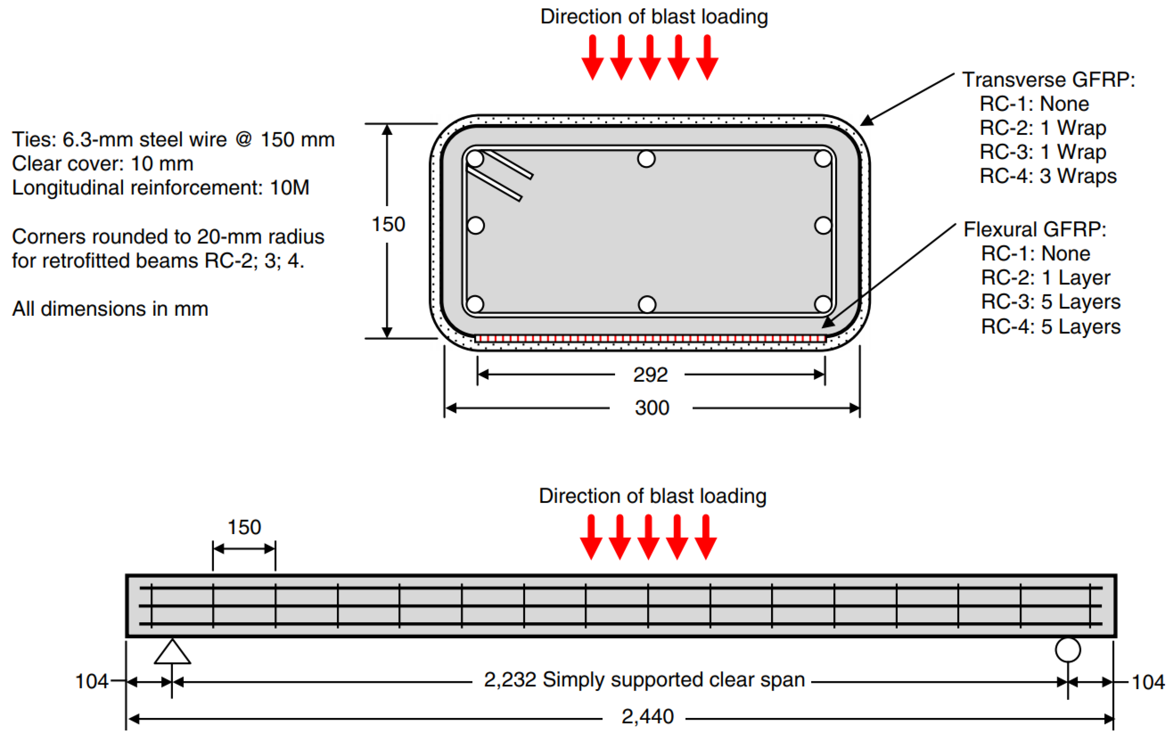
Burrell et al., 2015 [82] conducted small-scale blast tests on columns measuring 2468 mm in length and 152 mm × 152 mm in cross-section. Both steel fiber-reinforced concrete (SFRC) and conventional RC columns were tested, with some incorporating seismic detailing. An axial load of 294 kN was applied. Blast effects were simulated using a shock tube, and the resulting failure patterns were observed (Figure 12 [82]). Eight columns were tested—two with plain self-compacting concrete (SCC) and six with SCC containing steel fibers (0.5–1.5%) of types ZP-305 and BP 80/30. Transverse reinforcement spacing varied from 75 mm to 38 mm to study its influence. Compressive strength improved from 40.5 MPa to 56.6 MPa with fiber addition, and the modulus of rupture increased from 6.6 MPa to 7.7 MPa. Workability decreased with higher fiber content, with slump flow dropping from 625 mm to 390 mm. Longitudinal reinforcement consisted of four 11.30 mm bars (ρ = 1.72%, fy = 483 MPa), while transverse hoops followed CSA A23.3 (2004) [89] guidelines, using 6.30 mm steel wire at 75 mm (non-seismic) or 38 mm (seismic) spacing. The results showed that SFRC columns performed better in controlling damage and maximum and residual displacements. Seismic SFRC columns exhibited the highest resilience, although fiber addition alone did not prevent compressive rebar buckling in non-seismic columns.
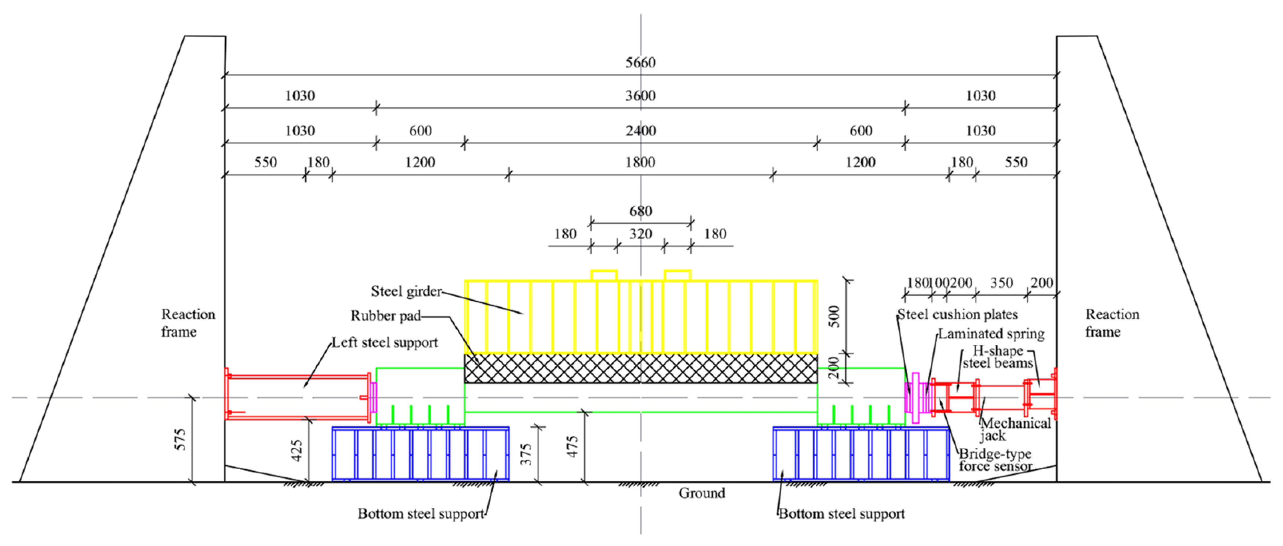
Focusing on high-strength materials, Xu et al., 2016 [76] investigated 2500 mm long, 200 mm × 200 mm UHPFRC columns under axial loads of 1000 kN in field blast tests. Explosive charges of 1 kg, 17.5 kg, and 35 kg were used at 1.5 m standoff, considering loaded and unloaded conditions (Figure 22 [76]). Eight columns were tested, four with UHPFRC (fc = 148 MPa) and four with conventional HSRC. Longitudinal reinforcement included eight 16 mm bars with 35 mm cover, confined with 8 mm stirrups at 100 mm c/c over 600 mm at both ends. Columns were exposed to different explosive yields to study elastic, plastic, and failure responses. UHPFRC columns significantly reduced maximum and residual displacements compared to HSRC. Damage patterns included concrete spalling, flexural failure, and combined flexure-shear failure. UHPFRC showed superior blast resistance and energy absorption.
To evaluate steel-concrete composite performance, Zhang et al., 2016 [77] conducted three field blast tests on 2500 mm long CFDST columns with core concrete under 1000 kN axial load. Explosives of 35 kg and 50 kg TNT were detonated at 1.5 m standoff. The steel tubes were 5 mm thick, with outer and inner dimensions of 210 mm × 210 mm and 110 mm × 110 mm. Some columns were unaxially loaded (S1 series), while others carried 1000 kN (S2 and S3). Maximum displacements ranged 36–50 mm, and residual displacements 8–22 mm. UHPC cores (fc = 170 MPa, ft = 33.8 MPa) allowed columns to resist blast overpressures of 20–30 MPa without tube buckling. FE models in LS-DYNA, validated against experiments, examined ALR, hollow section ratio, steel tube thickness, core strength, and cross-section geometry. Key findings included reduced displacement with higher ALR (< 0.60), minimal variation up to a hollow section ratio of 0.50, a significant displacement increase beyond 0.50, lower residual displacement with UHPC cores, and enhanced stiffness with thicker steel tubes, with outer tubes contributing more than inner ones.
Investigating reinforcement effects under demolition blasts, Yan et al., 2022 [86] tested RC columns to study the effect of longitudinal and shear reinforcement on damage. Eight specimens, 200 × 200 mm × 1200 mm, were exposed to 9 g of 2# emulsion explosives in 20 mm diameter, 120 mm deep boreholes. Concrete compressive strength was 58.5 MPa. Longitudinal bars ranged 8–14 mm (fy = 428–461 MPa), shear bars 2–6 mm (fy = 217–438 MPa) with spacing of 60 or 80 mm. Larger longitudinal bars reduced bending deflection (63.5 mm → 23.0 mm) and exposed steel length (535.5 mm → 500.3 mm). Shear reinforcement had a more pronounced effect; closer stirrup spacing limited cracking. Energy utilization remained low, around 2% of explosive energy. Empirical equations for damage estimation were proposed, highlighting the need for further tests.
To simulate far-field blast effects, Liu et al., 2025 [103] investigated post-blast behavior of RC columns using drop-weight impacts on 2:3 scaled 200 mm × 200 mm columns of 2400 mm height (Figure 23 [103]). Five scenarios (C1–C5) varied drop heights from 0.5 m to 4.0 m, producing impact energies of 4.9–39.2 kJ (scaled TNT 3.94–19.52 kg). Concrete compressive strength was 29.4 MPa, with four 12 mm longitudinal bars (fy = 515 MPa, cover = 15 mm). The test setup consisted of a reaction frame along with steel supports at the bottom and sides. Rubber pads and laminated springs were used to maintain stable boundary conditions and ensure proper transfer of loads, as illustrated in Figure 23. The impact was applied through a steel girder fitted with cushion plates, creating a distributed shock effect. Bending-shear failure dominated, with cracks developing mid-span and at the ends, progressing to reinforcement buckling. Residual bearing capacity dropped from 1019 kN (C1) to 412 kN (C4). Modal analysis linked decreasing vibration frequencies to damage state. The modal shifts clearly showed a progressive loss of stiffness, highlighting how structural supports play a key role in intensifying local responses. Damage indicators based on maximum displacement and energy absorption correlated well with residual capacity. The study recommended combining displacement and energy absorption for reliable damage assessment and stressed larger datasets for refined empirical predictions [103].
Critical Discussion:
A clear pattern can be observed from these studies [76,77,82,86,103]. Columns reinforced with fibers, UHPC, or composite steel-concrete systems show noticeably better performance than conventional RC columns when subjected to blast loading. The inclusion of shear reinforcement and proper seismic detailing enhances energy absorption and helps in limiting residual displacements. Axial load further contributes to stability, reducing peak deflections. Numerical simulations, when validated against the experimental results, offer useful guidance for parametric studies and help in refining column design.

3.2. Studies on Rectangular Columns

  • Damage Assessment & Parametric Studies
Shi et al. (2008) [16] proposed a method to assess damage in RC columns subjected to blast loads. The approach is based on evaluating the remaining axial load-carrying capacity of the columns. Parametric studies were conducted to understand how concrete strength, column dimensions, and steel reinforcement ratio influence the pressure-impulse (P-I) response.
The damage criterion is defined as follows [16]:
D = 1 P N _ r e s i d u a l P N
where D is the damage index, P N _ r e s i d u a l represents the residual axial load capacity of the damaged column (MPa), and P N is the maximum axial load capacity of the intact column (MPa) [16]. The latter can be calculated using the formula proposed by MacGregor [104]:
P N = 0.85 f c A G A S + f y A S
f c is the concrete compressive strength (MPa), f y is the yield strength of longitudinal steel (MPa), A G is the gross cross-sectional area of the column (mm2), and A S is the total area of longitudinal steel (mm2).
Based on the damage index D, the column’s condition can be categorized into four levels [16]:
  • 0 ≤ D < 0.20—Low damage
  • 0.20 ≤ D < 0.50—Medium damage
  • 0.50 ≤ D < 0.80—High damage
  • D ≥ 0.80—Collapse
The P-I response for different damage levels can be plotted using [16]:
P P 0 D I I 0 D = A P 0 ( D ) 2 + I 0 ( D ) 2 β
P 0 D and I 0 D are the pressure and impulse asymptotes corresponding to damage index D (kPa and kPa-ms, respectively), while A and β are constants dependent on column configuration and damage severity. The asymptotes for different damage indices can be calculated as follows [16]:
i.
For low damage (D = 0.20) [16]:
P 0 0.20 = 1000 0.007   e ρ s 0.01 + 0.069 ρ s 0.01 + 0.034   e f c 30 0.835   l n H 4.0 + h 0.60 1.804 + 0.067   l n h 0.60 0.168
I 0 0.20 = 1000 0.053   e ρ s 0.01 + 0.107 ρ s 0.01 + 0.021   e f c 30 + H 4.0 0.207 + 1.203   e h 0.60 0.943   l n h 0.60 2.686
ii.
For medium damage (D = 0.50) [16]:
P 0 0.50 = 1000 0.143   l n ρ s 0.01 + 0.320   l n ρ s 0.01 + 0.063 e f c 30 + H 4.0 1.390 + 2.639 h 0.60 + 0.318   l n h 0.60 2.271
I 0 0.50 = 1000 0.837 ρ s 0.01 + 0.036 ρ s 0.01 + 0.235 e f c 30 + H 4.0 0.274 + 2.271   e h 0.60 0.998   l n b 0.60 5.286
iii.
For high damage (D = 0.80) [16]:
P 0 0.80 = 1000 0.062   l n ρ s 0.01 + 0.238 ρ s 0.01 + 0.291   l n f c 30 1.676   l n H 4.0 + 2.439   l n h 0.60 + 0.210   l n b 0.60 + 1.563
I 0 0.80 = 1000 3.448 ρ s 0.01 0.254 ρ s 0.01 + 1.20 f c 30 0.521 H 4.0 + 6.993 h 0.60 2.759   l n b 0.60 2.035
ρ s and ρ are transverse and longitudinal reinforcement ratios, H is the column height (m), and b, h are the column width and depth (m). It should be noted that the equations above are based on a steel yield strength of 500 MPa. For columns using steel with a different yield strength, an equivalent steel area may be considered [16].
A s e = f y 500 A s
A s e is the equivalent steel area, A s is the actual steel area, and f y is the steel yield strength.
Critical Discussion:
The damage assessment equations suggested by Shi et al. [16] provide a useful framework for evaluating the response of RC columns under blast loads, yet several limitations are noticeable. The damage index depends only on residual axial capacity, leaving out flexural, shear, or combined failure modes, which can be critical during high-intensity blasts. The P-I asymptote equations (Equations (9)–(14)) are largely empirical, with coefficients calibrated for specific column geometries, reinforcement ratios, and steel yield strengths (fy = 500 MPa). This restricts their applicability to other column sizes, materials, or detailing. Additionally, these equations assume uniform material properties and do not account for dynamic strain-rate effects in concrete and steel, which can significantly affect blast performance. Interactions between axial load, boundary conditions, and local failures, such as spalling or bar buckling, are also not explicitly addressed. The use of equivalent steel area (Equation (15)) provides only a linear correction for varying fy, without capturing complex post-yield behavior or confinement effects. While these equations are useful for preliminary assessments and parametric studies, their accuracy under extreme blast conditions or for advanced materials like UHPC, SFRC, or composite columns is limited. Experimental validation or detailed numerical modeling is essential for reliable design.
  • Strengthening with FRP Wraps
Two studies have explored the use of FRP wraps to improve the blast resistance of RC square columns. Jacques et al. (2015) [105] performed explosion tests on RC columns measuring 2440 mm in length and 300 mm × 150 mm in cross-section, retrofitted with glass-fiber-reinforced polymer (GFRP) wraps. A shock tube was used to apply different blast pressures. Among the four normal-strength concrete columns, one was kept un-strengthened as a control (RC-1), while the remaining three (RC-2 to RC-4) were wrapped with GFRP on all faces, as shown in Figure 24 [105].
The columns were reinforced with eight Grade 400 steel bars of 11.30 mm diameter, having a yield strength of 445 MPa and ultimate tensile strength of 550 MPa [105]. Lateral confinement was provided using 6.30 mm diameter hoops of non-deformed steel wire with yield and ultimate strengths of 582 MPa and 670 MPa, respectively [105]. Concrete mixes included 10 mm coarse aggregate, with compressive strengths of 38.5, 32.8, 30.8, and 30.4 MPa for RC-1 to RC-4. The GFRP used had a tensile strength of 575 MPa, ultimate strain of 2.2%, modulus of 26.1 GPa, and nominal thickness of 1.18 mm. The results demonstrated that GFRP wrapping improved blast resistance considerably. Maximum displacement and damage were reduced compared to the unwrapped column (Figure 25 [105]). The study observed a clear trend: increasing longitudinal GFRP layers led to better performance. RC-4, with five layers of flexural GFRP and three transverse wraps, exhibited the best overall behavior under blast loading.
Similarly, To et al. (2025) [106] studied how AFRP-retrofitted RC columns behave under blast loading. The work combined FE simulations (LS-DYNA MM-ALE) with two fast ML surrogate models: ANFIS and a deep recurrent neural network (DRNN). Six input parameters were considered for the ML models: scaled distance (Z-scale), type of retrofit (as-built or AFRP-retrofitted), AFRP ultimate tensile strength (fju), AFRP thickness (tj), AFRP effective length (Lj), and concrete compressive strength (f′c). The models predicted two outputs in normalized form: the blast ductility ratio (µblast) and an energy-based damage demand (DB). A database of 168 FE simulation cases was created to train and test the models. For ANFIS, an 80/20 split was used (151 training samples and 17 test samples) with Gaussian membership functions, a Sugeno inference system (27 rules with two inputs per rule), and hybrid learning combining least-squares and gradient descent. Input features were normalized before training. ANFIS results matched the FE simulations very well, with R2 values of 0.999 for training, 0.970 for testing, and overall R2 around 0.998, while the mean absolute error and the root mean square error were 0.036 and 0.107, respectively.
The DRNN used an 80/10/10 split for training, validation, and testing. Manual tuning was carried out to finalize the architecture with two hidden recurrent layers (64 and 32 neurons), ReLU activations, Adam optimizer (learning rate 0.005), 0.2 dropout, and early stopping with a patience of 20. Convergence happened around epoch 11. DRNN performance was excellent: R2 of 0.9996 for training, 0.9997 for validation, 0.9994 for test, with MAE of 0.032 and RMSE of 0.033.
Both surrogate models predicted FE outputs within roughly 5% error. The DRNN was considered slightly better due to higher accuracy and lower errors. These models were then used to study parametric effects, such as confinement ratio and effective bond length, and to develop a practical cost-performance index for AFRP retrofitting design.
AFRP jacketing significantly enhanced blast performance [106]. Peak displacement dropped by 31.1%, and residual displacement decreased by 64.6% relative to un-strengthened columns. Blast ductility demand, calculated from pushover-derived yield displacement of 11.8 mm, showed a peak blast-induced displacement of 7.21 mm, keeping the ductility ratio within life-safety limits (Z = 0.55 m/kg1/3) [106]. The Park-Ang damage index indicated heavy damage for as-built columns (~0.777), while AFRP-retrofitted columns showed only moderate to superficial damage [106].
Parametric studies highlighted that a retrofit length-to-height ratio (RH) of 0.3–0.4 and a confinement ratio (CR) ≥ 0.07 offered the best trade-off between cost and performance. Additionally, two ML surrogate models, ANFIS and DRNN, trained on 168 FE-generated datasets, demonstrated strong correlation with FE results (R2 > 0.95, MAE < 0.05). The study recommended extending this surrogate modeling approach to CFRP, GFRP, and hybrid FRP systems, especially under multi-hazard conditions.
  • Influence of Cross-Section Geometry
Contact explosion tests were performed by Dua et al. (2020) [69] on 3300 mm long free-standing RC columns with both square and rectangular cross-sections to investigate how width influences blast resistance. The study also investigated the residual axial load capacity of these columns after blast exposure. Six columns were cast using 25 MPa concrete. Out of these, three columns had square cross-sections measuring 300 mm × 300 mm, with an axial load capacity of 2431 kN [69]. The other three were rectangular, with cross-sections of 300 mm × 500 mm, 300 mm × 700 mm, and 300 mm × 900 mm. Their reinforcement ratios were 0.0081, 0.0060, and 0.0060, giving axial capacities of 3044 kN, 4028 kN, and 5206 kN, respectively.
The square columns were anchored on isolated footings measuring 900 mm × 900 mm × 450 mm, buried 900 mm below ground [69]. Rectangular columns had correspondingly larger footings: 1100 mm × 900 mm × 450 mm, 1300 mm × 900 mm × 450 mm, and 1500 mm × 900 mm × 450 mm. Longitudinal reinforcement in rectangular columns used 16 mm diameter steel bars, while transverse reinforcement comprised a single master tie (hoop) with an open tie in one direction (10 mm diameter @ 100 mm c/c) [69]. Steel properties were 400 MPa yield strength and 540 MPa ultimate tensile strength.
Square columns were subjected to three TNT charges, 1 kg, 0.50 kg, and 0.115 kg, to determine the charge required to completely crush the concrete and reduce residual axial capacity to zero [69]. Rectangular columns were tested only with 0.50 kg TNT, as this was sufficient to destroy the square columns, helping identify column widths capable of limiting 2D blast wave propagation. Numerical validation was performed using LS-DYNA with the Mat_Concrete_Damage_Rel3 model, simulating free air and explosive behavior according to previously established formulations [69].
1 kg TNT contact explosion caused severe damage in the lower 375 mm of the square column, with an additional 250 mm of spalling along all sides (Figure 26a, reported in [69]). The 0.50 kg TNT mainly crushed the concrete cover up to 675 mm from the base and heavily damaged the core (Figure 26b [69]). Both cases resulted in zero residual load-carrying capacity; so, further axial testing was not carried out. The 0.115 kg TNT caused a crater of 180 mm on the blast face, which merged with 400 mm side spalling (E-115-300, Figure 27, reported in [69]). No spalling appeared on other faces, but horizontal cracks developed across them.
Rectangular columns of 300 mm × 700 mm and 300 mm × 900 mm showed spalling on the blast face and cracking on the remaining faces. The 300 mm × 700 mm column developed a 300 mm diameter crater. The 300 mm × 500 mm column exposed to 0.50 kg TNT (E-500-500) suffered a 350 mm crater on the blast face, with additional spalling on the other faces and cracks in the concrete core (Figure 27, reported in [69]).
Residual axial load tests were conducted only on E-115-300 and E-500-500 columns. A 400 T hydraulic jack applied load via a load cell mounted on the column top (Figure 26c). A damage index, D, was calculated to quantify the extent of damage from the contact explosions, following Equation (16) [69].
D = 1 P r P o
P r is the residual axial capacity and, P o is the original capacity. The 300 mm × 500 mm column (E-500-500) retained 901 kN, corresponding to D = 0.70. Damage was localized to the blast-affected zone, showing compression failure (Figure 28, reported in [69]). Blast performance improved with increased column width. Rectangular columns exhibited higher resistance compared to square columns, indicating that width plays a significant role in limiting both spalling and core damage under contact explosions.

3.3. Studies on Circular Columns

  • Material Enhancement & Coatings
The use of material enhancements and specialized coatings has shown promising results in improving the blast resistance of RC columns. Several studies have explored different approaches to strengthen columns against contact and close-in explosions.
To assess the effectiveness of composite coatings, Roller et al., 2013 [107] investigated free-standing circular RC columns of 150 mm diameter, spirally reinforced, and strengthened using various composite coatings. The coatings included 15 mm layers of Slurry Infiltrated Fiber Concrete (SIFCON), Ductile Concrete (DUCON) with coarse and fine meshes, and UHPC. Explosive loading was applied using spherical PETN charges. Four columns were tested, one uncoated control and three coated specimens, with reinforcement comprising 8 steel bars of 7.5 mm diameter.
The results showed a notable improvement in residual axial load capacity for coated columns, which increased roughly 10–15 times compared to the un-strengthened column under contact detonation (Figure 29a, reported in [107]). Among the coatings, SIFCON and polymer-based DUCON demonstrated the highest effectiveness, achieving a residual load capacity ratio of around 70%, while DUCON-fine and DUCON-coarse showed 65% and 50%, respectively (Figure 29a). For close-in blasts at a 0.20 m standoff, DUCON-coated columns carried axial loads about 4–5 times higher than the unprotected column (Figure 29b, reported in [107]).
Damage patterns differed significantly between strengthened and unprotected columns. Strengthened columns exhibited only localized cratering, while the unprotected column faced severe cross-sectional damage (Figure 30, reported in [107]). Specifically, a 50 mm thick SIFCON coating provided superior performance under contact blasts, maintaining high residual load capacity (≈70%) and minimal cracking. For close-in explosion loading, the 50 mm thick DUCON-fine coating delivered the best response, combining enhanced axial load capacity with reduced structural damage.
Focusing on composite and high-performance materials, Guo et al., 2017 [108] examined circular reactive powder concrete-filled steel-tubular (RPC-FST) columns measuring 2500 mm in length under axial load and ISO-834 standard [109] fire conditions. The steel tubes had an outer diameter of 194 mm, thickness of 6 mm, yield strength of 350.5 MPa, ultimate tensile strength of 370.2 MPa, and Young’s modulus of 206 GPa. The RPC core had a compressive strength of 116.2 MPa and a Young’s modulus of 40.2 GPa. Four columns were tested after 28 days of natural curing. The columns were positioned horizontally inside a gasoline-fired furnace, supported at both ends with fire-resistant bricks (Figure 31a, reported in [108]). Temperature-time histories were recorded for fire durations of 60 min and 105 min, reaching peak temperatures of 950 °C and 1040 °C (Figure 31b). Explosive loading was applied using spherical TNT at a standoff distance of 1.5 m in free air, with charge weights of 17.5 kg and 35 kg. All columns displayed flexural failure under explosive loading, with maximum mid-span displacements increasing for longer fire exposure due to localized plastic deformations. Prolonged heating from 60 min to 105 min promoted the formation of plastic hinge-like regions. A reduction in scaled distance shifted the failure mode from purely flexural to a combined flexure-shear type [108]. Experimental observations showed good agreement with predictions from the modified Girgorian model implemented in LS-DYNA.
  • Composite/Double-Skin Tubular Columns (DSTC, CFDSST, RPC-FST)
Several studies have focused on understanding the blast behavior of composite and double-skin tubular columns, including CFDSST, DSTC, and RPC-FST types. Zhang et al. (2015) [110] developed FE models for 2500 mm long concrete-filled double-skin steel tube (CFDSST) columns without core concrete. Both circular and square cross-sections were analyzed under axial loads of 2500 kN, subjected to TNT charges of 20, 40, 60, and 80 kg at a standoff distance of 1.50 m in free air. LS-DYNA simulations used the KCC Mat_Concrete_Damage_Rel3 model for concrete, while steel tubes were modeled using PLASTIC_KINEMATIC (MAT_003) and air blasts with the CONWEP model. Circular columns had outer diameters of 210 mm and inner diameters of 100 mm; square columns had outer and inner side lengths of 210 mm and 100 mm, respectively. Steel properties included density 7830 kg/m3, yield strength 300 MPa, Young’s modulus 200 GPa, and Poisson’s ratio 0.28.
Parametric studies examined concrete strength (30–60 MPa), tube thickness (2–5 mm), column cross-section, hollowness ratio (0–0.75), support conditions, and ALR from 0–50% of ultimate axial capacity. The results indicated that the outer steel tube largely controlled maximum displacement, while inner tube thickness had limited effect. Circular columns performed better under explosive loads above 40 kg TNT. Hollowness ratios up to 0.50 had minor influence on mid-height displacement. For pinned columns, ALR significantly affected displacement, while fixed supports showed minimal sensitivity.
In a subsequent study, Zhang et al. (2016) [111] evaluated 2500 mm long CFDSST columns filled with ultra-high-performance concrete (UHPC) under close-in air blasts. Columns were square and circular, carrying 1000 kN axial load, and subjected to TNT charges of 17.2, 35, and 50 kg. UHPC-filled columns (compressive strength 170 MPa, tensile strength 33.8 MPa) demonstrated substantially improved blast resistance over normal-strength concrete counterparts. Peak overpressures and impulses matched CONWEP predictions with about 18% difference, confirming that UHPC cores enhance structural resilience and reduce deformation and spalling.
Wang et al. (2018) [112] numerically studied 2500 mm long circular hybrid FRP-concrete-steel DSTC columns under a 10 kg TNT blast at 1.50 m standoff. The blast load was simulated using the CONWEP model [22], with the explosion height set at 1.25 m. The outer tube was 5 mm carbon-FRP, the inner tube 5 mm steel, and the concrete core had 40 MPa compressive strength. LS-DYNA simulations, validated against experimental data, showed highly ductile behavior. FRP tubes effectively confined concrete, particularly under high blast pressures. Parameters like inner steel thickness, hollowness ratio, ALR, and fiber orientation strongly influenced blast resistance, while concrete strength and outer CFRP thickness had smaller effects. Further observations indicated that the FRP confinement became increasingly critical with higher blast pressures. Comparisons revealed that CFDSST columns offered superior blast performance.
Field explosion experiments were conducted by Li et al. (2019) [113] on a 2500 mm long CFDSST column. Explosive charges of 5 kg and 8 kg TNT were used at standoff distances of 0.20 m and 0.30 m in free air. The detonation point was fixed at 0.50 m above the column base. Three columns (C1–C3) were tested, each with an internal diameter of 159 mm, outer diameter of 325 mm, and steel tube thickness of 6 mm. The concrete had an average 28-day cube compressive strength of 41.90 MPa. All columns were loaded axially with a working load of 500 kN. Each column rested on a RC footing measuring 1000 mm × 1000 mm × 500 mm. A steel reaction frame was used to apply and maintain the axial load. The footings were cast level with the ground, and any gaps around the base were filled with sand. The top of each column was connected to a steel beam through a hinge, creating a fixed–pinned support condition. Axial loads were transmitted using four rolled steel bars linking the top and bottom beams, which were tensioned with a hydraulic jack (Figure 32a, reported in [113]). Explosives were prepared as brick-shaped TNT blocks of dimensions 100 mm × 50 mm × 25 mm, weighing 0.20 kg each, and placed on a wooden supporting frame (Figure 32b). The mechanical properties of the steel tubes were measured: the inner 159 mm × 6 mm tube had a yield strength of 348.6 MPa, ultimate tensile strength of 516.6 MPa, and 25.2% elongation, while the outer 325 mm × 6 mm tube had a yield strength of 337.4 MPa, ultimate strength of 428.8 MPa, and 23.9% elongation. For numerical validation, LS_DYNA was used with the Karagozian & Case Concrete (KCC) damage model (Mat_Concrete_Damage_Rel3). The column was discretized using 8-node solid hexahedral elements with a 10 mm mesh size. Concrete density was taken as 2400 kg/m3. Steel properties were density 7850 kg/m3, Young’s modulus 206 GPa, and Poisson’s ratio 0.30. Free air was modeled using MAT_NULL (MAT_009) combined with a linear polynomial equation of state, as given in Equation (17) [113].
P = C 0 + C 1 μ + C 2 μ 2 + C 3 μ 3 + ( C 4 + C 5 μ + C 6 μ 2 ) E 0
where, E 0 is the initial internal energy per unit volume of explosive (J/m3); μ denotes volumetric strain ( ρ / ρ 0 − 1); C0 to C6 are polynomial coefficients. For ideal gases, the constants simplify to C0 = C1 = C2 = C3 = C6 = 0, and C4 = C5 = γ − 1, reducing Equation (17) [113] to the gamma-law EOS, Equation (18):
P = γ 1 ρ a ρ a 0 E 0
where, ρ a and ρ a 0 are the current and initial air densities, respectively, and γ is the adiabatic index [113]. Under standard atmospheric conditions, γ = 1.40 and E 0 = 2.50 × 10⁵ J/m3. Coefficients C4 and C5 were taken as 0.40 [113].
Explosive behavior was modeled using the Jones-Wilkins-Lee (JWL) equation of state [113]:
p = A 1 ω η R 1 e R 1 η + B 1 ω η R 2 e R 2 η + ω η ρ 0 E
where, p is blast pressure; A and B are linear coefficients; ω , R 1 , and R 2 are non-linear constants, η = ρ / ρ 0 , ρ 0 is initial density, E is internal energy per unit volume. The adopted values were: A = 371.20 GPa, B = 3.23 GPa, ω = 0.30, R 1 = 4.15, R 2 = 0.95, ρ 0 = 1630 kg/m3, and E = 7 × 10⁹ J/m3, and detonation velocity was 6930 m/s [113]. Column C-1, subjected to 5 kg TNT at a height of 0.40 m and standoff distance of 0.30 m, showed no significant cracking, as shown in Figure 33A reported in [113]. However, severe spalling occurred at the footing edges, exposing the reinforcement, as shown in Figure 33B. When the same explosive was detonated at 0.50 m height and 0.20 m standoff, only localized denting was observed near the blast site. LS-DYNA simulations closely matched these observations, as shown in Figure 33 (as reported in [113]). Column C-2, exposed to 5 kg TNT at 0.50 m height and 0.20 m standoff, experienced pronounced deformation between 300 mm and 700 mm from the base. Maximum experimental deformation was 29.30 mm at 450 mm height, while the numerical prediction was 24 mm at 500 mm, confirming the model accuracy, as shown in Figure 33C. Column C-3, subjected to 8 kg TNT at the same height and standoff, developed significant denting, with a maximum displacement of 77.70 mm over a 400–500 mm region above the footing, as shown in Figure 33D. LS-DYNA predicted a maximum of 63.70 mm at 500 mm height. Experimental deformation in C-3 was 2.17 times that of C-2. Removal of concrete around dented regions revealed inner steel tube deformation, consistent with outer tube behavior, while the inner tube was severely crushed near the detonation zone, as shown in Figure 34 (as reported in [113]). Analysis of internal energy showed that energy imparted to columns increased with explosive yield. Over 70% of this energy was absorbed by the concrete core, highlighting its critical role in blast resistance. Steel tubes, though absorbing less energy, confined the core radially and circumferentially, enhancing energy dissipation.
Further investigations have considered axial load effects on Column C-2 [113]. Axial loads of 0, 500, 1000, 1500, and 2000 kN were applied. Maximum denting depth slightly increased with higher axial loads, indicating that axial pre-stress influences local deformation but does not drastically alter overall blast response.
Segmental and steel-encased tubular columns have also been examined under explosive loading. Do et al. (2020) [4] investigated 1500 mm long precast concrete segmental columns (PCSC) and steel-encased versions (PCSC-FST) under blast using LS-DYNA. Both columns had 150 mm diameter, with PCSC made of five 300 mm segments reinforced with longitudinal and transverse steel, and PCSC-FST unreinforced but confined by a 2.90 mm steel tube. A central steel duct housed a 13 mm tendon, pre-stressed to 47% of its tensile capacity. Concrete compressive strength was 43 MPa. The results showed that steel confinement improved performance, altering failure from local segment cracking to global tendon rupture. PCSC columns outperformed PCSC-FST under blast loading.
Critical Discussion:
Collectively, these studies [4,110,111,112,113] indicate that double-skin and composite tubular columns, whether CFDSST, DSTC, or RPC-FST, show much better blast resistance than conventional single-skin columns. The thickness of the outer tube, type of material used (such as UHPC or FRP), and the column’s cross-section play a major role in controlling deformation. Steel confinement helps improve ductility and reduces local failures, while hybrid combinations of FRP, steel, and concrete can further boost performance. When designed carefully, DSTC and CFDSST columns exhibit excellent resilience under extreme blast loads, making them highly suitable for protective structures.
  • Experimental Validation of RC Circular Columns
Rhouma et al. (2025) [114] executed both experimental and numerical work to study the blast behavior of circular RC columns under localized blast loading. Eight simply supported columns were tested, each 1800 mm long and 100 mm in diameter. These were reinforced with 3 mm longitudinal bars, 2 mm transverse ties and had a 10 mm concrete cover. The average 28-day compressive strength of concrete was about 22.4 ± 1.6 MPa. Blast loading was created using an explosive-driven shock tube (EDST) with 30 g C4 charges, triggered by a 1 g TNT detonator (see Figure 35, reported in [114], which shows the setup of the EDST, including the steel reaction frame, shielding plates, and the RC column fitted with instruments). Reflected peak pressures of nearly 15.1 ± 0.9 MPa and impulses of 2.2 ± 0.1 MPa·ms were recorded. High-speed cameras with 50 mm lenses were used to capture the fast, transient response. Bright LED lights illuminated the setup, while a speckle pattern was applied on the column surface to enable Digital Image Correlation (DIC). Mid-span deflections varied between 19 mm and 55 mm depending on reinforcement levels, while fixity rotations ranged from 1.35° (moderate damage) to 3.9° (heavy damage).
Numerical modelling was executed in LS-DYNA R10 using the Karagozian and Case concrete model with ALE formulation for blast–air interaction [114]. The FE model matched experimental peak deflections with only 1.1–1.8% difference and reproduced crack patterns observed through DIC. The findings showed that lowering reinforcement ratio sharply increased deflections and cracking, underlining reinforcement detailing as a key factor in blast resistance [114]. A major highlight of the work was the use of high-speed stereoscopic DIC to capture crack initiation at about 0.95 ms and crater formation near mid-span at around 38 ms. The study suggested that future work should focus on full-scale members and different strengthening methods, as current observations were restricted to lab-scale specimens.
  • Multi-Hazard & Retrofit of Bridge Columns
Alomari and Linzell (2025) [115] studied the behavior of RC bridge columns exposed to a sequence of fire, truck impact, and air blast using validated 3D FE models in LS-DYNA. Figure 36 [115] presents the order in which the loading demands were applied to the isolated bridge columns. The RC column, along with the spread footing and supporting piles, was originally designed as per the Federal Highway Administration (FHWA) design example shown in Figure 37 [115]. Figure 38 [115] shows a pendulum setup with a swing radius of 2850 mm. It carried a 60 kg impactor that hit the column at a height of 570 mm. The impact was applied above a steel base plate of 25 mm thickness. Circular columns of 750, 1050, and 1350 mm diameter were considered, with concrete compressive strength of 28 MPa and steel yield strength of 475 MPa. After 90 min of ISO-834 [109] fire exposure, the 750 mm column retained only 26% of its axial load capacity, showing major thermal damage. The study considered a Ford F800 truck, weighing 8175 kg, crashing into the columns at a speed of 120 km/h. After this impact, a blast was simulated using a TNT charge, placed at a scaled distance of 0.25 m/kg1/3, and analyzed through the Multi-Material Arbitrary Lagrangian-Eulerian method.
To restore strength, two CFRP retrofitting methods were checked [115]. The first used full, partial, and intermittent wraps with thickness from 0.5–2.0 mm. The second combined wraps with near-surface-mounted CFRP bars. Full wrapping up to 1.5 mm thickness (W-9L) gave the best balance, cutting peak displacement by about 40% and kinetic energy by 53%. Beyond 1.5 mm, improvement was negligible. Partial lower-half wrapping (HH-9L) and intermittent wrapping with 1000 mm strips (I1000-9L) performed nearly as well, reducing displacements by 51–58% and restoring 51–54% axial capacity [115]. Narrower intermittent strips (I500-9L) and hybrid reinforcement showed weak results, with heavy spalling and cracking. Larger columns also showed lower retrofit gains due to less slenderness and higher load demand.
The work highlighted CFRP wrapping, especially partial or full 1.5 mm wrapping, as a practical solution for strengthening fire-damaged RC columns against combined blast and impact. Further research was suggested on experimental validation, size-based optimization, and design code inclusion.

4. Progression of Studies

Based on the detailed review in the earlier sections and careful analysis of past experimental and numerical studies, this section presents a summary of how research on RC columns under blast loading has progressed over time.
Experimental studies have helped in understanding local damage such as spalling, scabbing, and buckling of reinforcement bars. These studies also revealed that column geometry plays a significant role in governing failure mechanisms. Square columns often experience localized spalling and crushing of the cover concrete. Flexure-shear interactions are common, and at higher axial loads, reinforcement buckling becomes a major concern. Rectangular columns behave differently due to their longer sides. The surfaces facing a blast can suffer severe cratering and spalling, while the remote surfaces develop flexural cracks. This often leads to core crushing and partial loss of residual strength. Wider rectangular columns tend to be better confined and are less vulnerable than square ones. Circular columns, especially when strengthened with spirals or composite jackets, show more uniform stress distribution and less spalling. They usually fail by local cratering, flexural hinging, or, under heavy loads, a mix of flexure-shear or tube denting in composite types. Using high-performance materials or FRP wraps can improve performance, turning brittle shear or spalling failures into more ductile, flexure-dominated behavior.
Recent experimental findings also show that factors like ALR, reinforcement layout, and explosive configuration (e.g., cylindrical vs. spherical charges) greatly influence damage distribution. When the ALR is kept below 0.6, the overall deflection remains lower, but higher values often lead to crushing or shear-type failures. In the same way, charges ignited from both ends cause more intense local damage because of the Mach reflection (self-Mach-stem effects).
But because of safety issues and limited scale, the focus of research gradually shifted towards numerical simulations. Earlier FE models mostly used simple load functions like CONWEP and basic material laws, which could not capture strain-rate effects or progressive failure. Later, advanced concrete models like Karagozian & Case Concrete (KCC), Riedel-Hiermaier-Thoma (RHT), and Concrete Damage Plasticity (CDP) were adopted. These included strain-rate strength, multiple failure modes, and better representation of material behavior.
A major development in this stage was the inclusion of strain-rate effects in material models. Under blast or impact conditions, strain rates can range from about 100 to 104 s−1 (commonly 102–104 s−1 for many concrete blast tests), much higher than those in normal quasi-static tests. Such high rates change both the apparent strength and the deformation behavior of materials. Concrete, for instance, shows higher compressive and tensile strength but tends to lose ductility, with faster post-peak softening. This often causes brittle spalling or scabbing near the surface under load. Steel reinforcement also benefits from dynamic strengthening, which can be captured through empirical models like Cowper-Symonds or Johnson-Cook. Meanwhile, FRP composites and polymer adhesives stiffen due to viscoelastic effects at high strain rates. To capture these effects in simulations, DIFs are widely used, or rate-dependent constitutive laws such as KCC, RHT, or rate-modified CDP are applied. Calibration with high-strain-rate experiments, like Split Hopkinson Pressure Bar (SHPB) tests, is critical to correctly predict fragmentation, bar buckling, and residual strength. Ignoring these rate effects often leads to overestimation of ductility or underestimation of local damage, producing non-conservative results.
With time, techniques such as erosion, energy-based failure limits, and DIFs for both concrete and steel were also added. Methods like ALE and CEL made it possible to study shock waves and fluid–structure interaction, which older analytical and SDOF methods could not explain. These developments allowed for detailed studies on ALRs, reinforcement detailing, slenderness, and retrofitting, bringing the simulation results closer to the experimental observations.
Among the commonly used constitutive models for impact and blast analysis, two stand out: the KCC model, often seen in LS DYNA or AUTODYN as MAT_072R3/Mat_Concrete_Damage_Rel3, and the CDP model, available in ABAQUS/CAE and other solvers. Both can capture crushing, cracking, and confinement effects, but they differ significantly in their formulation, calibration needs, and suitability for specific blast scenarios. KCC is designed for high strain rate, short-duration events. It performs very well in explicit hydrocode simulations and can reasonably predict spalling and fragment ejection when properly calibrated and meshed. On the other hand, CDP offers a more straightforward plasticity-damage framework. It can be calibrated easily from standard laboratory stress–strain data and works well in problems combining quasi-static and dynamic effects, such as axial load + blast. For extremely high-rate blasts, standard CDP requires additional rate augmentation, as strain-rate effects are not inherently captured. In practice, it is advisable to: (i) use KCC for near-field or contact detonations where high-rate experimental data are available; (ii) prefer CDP when dealing with coupled static-dynamic scenarios or when only conventional material tests are on hand; and (iii) always run a concise benchmark comparing both models, report full parameter sets, and perform mesh/erosion sensitivity checks to ensure predictive confidence.
Recent research has introduced several empirical and semi-empirical damage indices, such as those based on displacement and energy, to assess the remaining strength of columns more accurately. These approaches help connect findings from experiments with numerical results. Alongside this, hybrid modeling methods, using segmental or composite sections combined with dynamic load effects, are being developed to better represent how full-scale structures behave under contact or near-field explosions.
It is important to point out that many studies using numerical analysis tools or commercial software do not clarify whether genuine or pirated versions were used. In many cases, the exact version of the software is also not disclosed. Relying on pirated software brings several risks. Without official updates or patches, the predictions of structural responses may become unreliable.
Validating the simulation results with dependable field or laboratory data is equally crucial. Without proper calibration against real test results, studies often overestimate column strength or fail to capture spalling damage accurately.
More recently, research has started using data-driven and hybrid methods to reduce the high computational cost of nonlinear FE models. Large databases created from many validated FE simulations are now used to train machine learning and deep learning models. These can quickly predict responses like mid-span deflection, residual capacity, and overall blast damage. Techniques such as XGBoost, CatBoost, and Graph Neural Networks have shown very high accuracy, often above R2 = 0.95, while cutting down analysis time drastically. Probabilistic methods like NGBoost and ML-based Monte Carlo simulations are also being used to generate fragility curves and study uncertainty in blast conditions. Hybrid systems are also emerging, where ML models work alongside FE solvers. Here, the FE part captures nonlinear damage, while ML speeds up sensitivity and reliability checks. A major concern with these approaches is the lack of clarity in many studies regarding training data, feature selection, or hyperparameter tuning. This often results in overfitting and reduces the ability to generalize the results. In the case of hybrid frameworks, the absence of open-source implementation details makes it difficult to reproduce and validate the findings. Despite these concerns, the field is moving from purely deterministic analysis to faster, uncertainty-aware frameworks.

5. Conclusions

This state-of-the-art review presents a detailed examination of the behavior and failure mechanisms of RC columns under blast loading. The study covers loading mechanisms, structural responses, and damage patterns, drawing upon previous experimental, numerical, and analytical investigations. Different methods for simulating blast effects, including simplified analytical techniques, FE models, and experimental approaches, are also discussed. Recent research has shown significant improvements in predicting flexural, shear, and combined failure modes using advanced FE models and ML techniques [96,97,98,101].
Based on the review of 40+ specific publications on RC columns under blast loadings, it appears that research in this field is still at an early stage. Cross comparison of existing studies is crucial to develop a more robust understanding. Current design codes largely rely on simplified approaches for predicting blast loads and designing structures to resist explosions [1,2,3,55]. While these methods can reasonably predict overall flexural and ductile responses, they fall short in capturing brittle failure, localized spalling, and shear-dominated damage modes.
Accurate assessment of blast threats remains challenging due to the variability in potential scenarios [1]. Load assessment aims to define a target threat level against which mitigation measures are implemented. Designs are then based on acceptable structural damage corresponding to this defined threat level. Complete immunity against all possible threats is not feasible; adaptive strategies that allow for future modification without major interventions to the parent structure are therefore necessary.
This review does more than just summarize existing literature. It presents a quantitative and comparative analysis, critically evaluating findings to highlight research gaps. The key findings on column behavior under blast loads are summarized in Table 5, Table 6, Table 7, Table 8, Table 9, Table 10, Table 11, Table 12, Table 13 and Table 14.
Based on evaluations of experimental data, empirical models, and numerical simulations, the following observations are drawn for columns with respect to different cross-sections.

5.1. Observations for Square Columns

  • Double-end-initiated cylindrical charges produce peak overpressures and impulses approximately 2–4 times higher than centre-point-initiated charges.
  • Reflected blast pressure from cylindrical charges was found to be twice that of spherical charges
  • Axial compressive load significantly affects blast resistance. Even less than half of the balanced axial load can considerably reduce the residual capacity under blast as compared to pure flexural capacity.
  • UHPFRC columns demonstrate reduced maximum and residual displacements compared to normal- and high-strength RC columns under similar blast pressures.
  • Increasing steel fibre content in UHPFRC from 2% to 4% improves column displacement resistance, but content beyond 4% can cause longitudinal bar rupture under close-in blasts.
  • Micro steel fibre-reinforced UHPC preserves over 70% axial load capacity after a 35 kg TNT blast, whereas high-strength RC columns retain only 40% capacity after an 8 kg TNT blast at 1.5 m standoff.
  • Larger cross-sections, higher transverse reinforcement ratios, reduced stirrup spacing, and thinner concrete covers enhance blast performance.
  • The damage criterion proposed by Cui et al. [3] is suitable for rapid damage assessment of RC columns under near-field blasts.
  • Increased shear/transverse reinforcement improves residual resistance post-blast.
  • Concrete-steel composite columns (RC with steel core) exhibit improved blast response and maintain higher post-blast load capacity than conventional RC columns.
  • SFRC significantly enhances column performance, reducing both maximum and residual displacements.
  • Thicker inner and outer steel tubes in CFDSST columns improve stiffness and reduce displacement, with the outer tube contributing more under close-in blasts.
  • Segmental columns show reduced spalling and displacement. Energy absorption between segments mitigates damage, and additional shear keys further improve resistance.
  • Confining/seismic reinforcement at the top, bottom, and mid-height regions reduces transverse displacement and cracking under near-field blasts.
  • ALR around 0.30 benefits blast resistance at scaled distances Z > 0.40 m/kg1/3, but higher ALR increases mid-height shear damage at Z < 0.40 m/kg1/3 [78].
  • Doubling concrete strength increases blast resistance by 1.5 times; while increasing reinforcement ratio 3.5 times raises capacity by 1.2 times under 11.2 MPa peak overpressure [90].
  • Steel-FRP wrapping of lower column halves enhances residual load by 10–15%, while two layers of transverse CFRP strips improve cracking resistance and residual capacity under close-in explosions.
  • Advanced FE models and ML techniques offer a much better prediction of mid-span displacement, damage indices, and residual capacity. These approaches clearly show where traditional SDOF or purely empirical methods fall short.
  • Graph Neural Networks can predict blast damage with very high accuracy in a fraction of the time, reducing computation by more than 10,000 times without losing precision.
  • Dimensional analysis along with FE simulations enables a straightforward prediction of mid-span disturbances during blast events. It effectively reflects the influence of explosive weight, standoff distance, and vulnerability limits. Significant damage, such as stirrup rupture and concrete spalling, is observed only when the scaled distance falls below a critical value (Z < 0.07 m/kg1/3).
  • Damage indicators that account for both displacement and energy absorption show stronger correlation with residual strength than using displacement alone.
  • Uneven chloride-driven corrosion greatly increases blast fragility in the long run, with risks becoming more severe after decades of exposure.
  • Assessments based only on ductility or residual strength often give different results; hence, a combined approach is essential for dependable design.
  • Off-center blast loading changes the failure behavior in a major way, especially under axial compression, stressing the importance of considering eccentric detonations.
  • Microscopic study showed that basalt and polypropylene fibers in RFRCAC columns acted as crack bridges and developed a good bond with the cement matrix. This improved the packing of coral aggregates and gave the columns much higher blast resistance than RCAC and conventional RC columns.

5.2. Observations for Rectangular Columns

  • Glass-FRP composite wrapping on all faces enhances blast performance.
  • Rectangular RC columns experience less damage under contact explosions compared to square columns, making them preferable for high-rise structures requiring higher blast resistance.
  • Aramid FRP (AFRP) jacketing showed a clear reduction in displacement and damage levels. Surrogate ML like ANFIS and DRNN, trained on FE data, provided dependable predictions and helped in balancing cost with performance during retrofit design.

5.3. Observations for Circular Columns

  • Thin layers of energy-absorbing materials such as SIFCON, DUCON, and UHPC significantly improve residual load capacity, with SIFCON-coated columns showing the best performance under contact blasts.
  • CFDSST columns outperform CFST and hybrid FRP-concrete steel DSTC columns in limiting mid-height transverse displacement under close-in blasts [112]. Steel tubes prevent spall, while plastic deformation of the concrete core contributes to energy absorption. UHPC further enhances performance. Circular CFDSST columns outperform square counterparts.
  • Increased thickness of inner and outer steel tubes improves stiffness; the outer tube contributes more to blast resistance.
  • Circular RC columns show lower peak deflections than square, hexagonal, and octagonal columns under similar blast conditions [23].
  • Numerical models using ANSYS AUTODYN, LS-DYNA, and ABAQUS/CAE with damage models such as Mazars, KCC, and CDP effectively validate the experimental results and simulate blast responses.
  • Probabilistic and ML models provide a quick and dependable way to assess displacement and the chances of failure. These models work well alongside experimental studies on axial loads and blast impacts.
  • Small-scale shock tube tests using stereoscopic DIC recorded crack initiation and crater formation within milliseconds. The results clearly showed that the reinforcement ratio played a crucial role in determining blast resistance.
  • RC bridge columns subjected to sequential hazards like fire, vehicle impact, and air blast showed cumulative damage. Fire caused a sharp drop in axial capacity, for instance, a 750 mm diameter circular column retained only about 26% of its original strength after 90 min of fire exposure. CFRP retrofitting, especially with full or partial 1.5 mm wraps, proved effective in restoring axial capacity (up to ~54%) and reduced peak displacement and kinetic energy under combined impact and blast conditions.
  • Columns with larger diameters showed lower retrofit effectiveness, mainly due to higher axial load demands and reduced slenderness.
These findings offer valuable guidance for structural engineers and committees developing blast-resistant design standards. This study also provides insight into column strengthening techniques that mitigate damage and reduce collapse risk from near-field and contact explosion scenarios.

6. Directions for Future Research

To gain a deeper understanding of the dynamic behavior of RC columns under contact and close-in explosions, the following future research directions are suggested:
  • Blast loading is affected not just by environmental factors like temperature, humidity, and wind, but also by the characteristics and aging of explosives, as well as their storage and handling. These aspects can change the pressure-time history and impulse distribution, which in turn impacts the behavior of RC columns. It is important that future experiments and numerical models take all these factors into account for more accurate results.
  • Effect of additional transverse reinforcement should be studied. This includes increasing bar diameter in the confining zones, mid-height region alone, or both regions, to see its impact on blast resistance.
  • There is a need to explore AI and ML methods along with probabilistic approaches for predicting blast damage. Combining these with Monte Carlo simulations can help account for variations in loads and structural properties.
  • New methods using GNNs and surrogate models like ANFIS and DRNN have shown quick and precise results for blast prediction. However, they still need to be tested on full-scale columns, multiple hazard cases, and aging conditions.
  • Future studies can focus on explainable AI frameworks that connect blast damage prediction with performance-based retrofit methods for RC columns. Tools such as partial dependence plots (PDP) and accumulated local effects (ALE) may be used to define clear retrofit limits for stiffness and confinement.
  • Simplified dimensional models should be extended to account for different axial loads, larger column sizes, and various retrofit methods to better predict column behavior under extreme conditions.
  • Support conditions in experiments and numerical models often do not match the real-life boundary conditions of actual structures. Laboratory supports, whether pinned, fixed, or simply supported, are idealized and cannot fully represent the interaction with slabs, beams, or the flexibility of foundations. This mismatch can result in differences in observed displacements, failure patterns, and remaining structural capacity.
  • Effect of off-center blasts should be studied.
  • Spatial variation and correlation of blast pressures from vehicle-borne improvised explosive devices need closer study. Adjacent RC columns are often subjected to related, yet not identical, air blast loads because of vehicle shielding and orientation. Considering this variability in experiments and reliability-based models can make the assessment of progressive collapse risk more accurate.
  • There is a need for experimental and numerical studies to validate CFRP retrofitting approaches for fire-damaged columns facing blast or impact, including determination of optimal thickness and coverage for columns of different dimensions.
  • Most studies focus on damage or crack patterns under blast loading. Detailed reporting of crack length, width, depth, and energy dissipated during damage will provide a more complete picture.
  • Damage evaluation needs common criteria that combine displacement, leftover strength, and energy absorption. Depending only on ductility can give a wrong picture of collapse.
  • In future studies, reporting damage indices along with probabilistic confidence intervals would help complement physical crack measurements and provide a more complete understanding of structural behavior.
  • The correlation between induced stresses and resulting damage should receive more attention to better understand failure mechanisms.
  • Determining the maximum explosive charge that a column can withstand at the minimum standoff distance without failure is critical.
  • Most studies have relied on idealized charges, such as spherical or cylindrical TNT equivalents, with uniform standoff distances. Future investigations need to consider irregular, multiple, or sequential blasts.
  • Combined influence of axial load, span length, and reinforcement detailing needs careful investigation. High-fidelity FE models should be used, and results must be verified through experiments, as these parameters play a crucial role in determining failure patterns and remaining load-carrying capacity.
  • Strategies to enhance blast performance without increasing the column’s cross-section need further exploration.
  • Strengthening damaged columns after blast exposure is an important area for study, including repair techniques that restore structural integrity.
  • Scaling up lab-scale stereoscopic DIC and shock-tube studies to full-scale members would help validate observed crack initiation and crater formation patterns.
  • Variation in bond strength between existing concrete and strengthening materials like UHPC or UHPFRC must be considered, as it affects load transfer and overall performance.
  • Special attention should be given to cases where ground shock and air-blast impinge the structure at the same time. This situation represents the most severe loading scenario, causing the highest structural demands because of the combined peak pressures and dynamic impacts.
  • Effectiveness of polypropylene fiber (PPF) overlays and other spall-resistant concretes should be systematically tested under near-field blasts.
  • A systematic benchmarking of concrete damage models (e.g., CDP, KCC, JHC, Mazars, Mat_Concrete_Damage_Rel3) across different FEM platforms under contact and near-field blasts is required.
  • Innovative strengthening concepts, such as using steel angle sections at column corners with batten connections, should undergo experimental and numerical validation for blast performance.
  • The comparative effectiveness of helical reinforcement versus traditional circular stirrups in circular RC columns under blast loads should be quantified in terms of confinement efficiency and energy dissipation.
  • Blast resistance of RC columns can be improved by using confinement methods that are different from the conventional transverse reinforcement. Innovative options like hexagonal or honeycomb-shaped steel tube confinement around the concrete core may help develop a triaxial stress state, which in turn can strengthen resistance against both penetration and blast.
  • Blast behavior of distressed or pre-damaged columns requires attention, as real structures often have existing flaws.
  • Fragility studies should account for time-based deterioration like uneven chloride-driven corrosion.
  • More detailed investigations are required to understand how RFRCAC columns perform over time in marine conditions. Exposure to corrosion, chloride penetration, and repeated wet-dry cycles can slowly weaken the bond between fibers and matrix, which may eventually reduce their blast resistance and durability.
  • Materials like UHPFRC, SIFCON, DUCON, and CFDSST provide very good blast resistance. However, many of these materials are costly, not easily available everywhere, and may not be practical for use in regular buildings. Future research should focus on a complete cost–benefit assessment, covering initial material cost, construction effort, maintenance, and the ability to repair after blast incidents.
  • Exploring low-cost alternatives, locally available materials, or hybrid solutions can also be beneficial. Such options may offer adequate blast resistance for non-critical structures without putting too much strain on the budget.
  • Most blast research has concentrated on well-engineered RC columns and high-performance buildings. On the other hand, non-engineered structures, low-rise buildings, and informal constructions receive very little attention.
  • CFDSST columns under contact explosions deserve dedicated experimental campaigns to establish design guidelines.

7. Research Gaps and Open Issues

This review summarizes experimental, numerical, and analytical studies on RC columns under blast loading. At the same time, it points out several important gaps that need attention:
  • In experimental blast testing, several on-ground challenges often arise. These include slight misalignment of explosive charges, delay or inconsistency in detonation timing, and uneven confinement around the specimen. Reflected pressure waves from nearby boundaries can also affect the results. Free-standing columns may become unstable during testing, and applying or maintaining a steady axial load at the moment of blast is often difficult. Sensors, too, tend to show temporary drift under high strain-rate conditions. Such practical issues are rarely measured or discussed in detail in most available studies.
  • Many numerical studies use empirical blast curves or simplified models. These lose accuracy at very short distances. For example, Kingery-Bulmash curves are not very reliable below ~0.40 m·kg−1/3. Better calibration with experiments and clear protocols for near-field or contact blasts are needed.
  • Even with recent developments, the use of ML and probabilistic models for assessing RC column blast resistance remains quite limited. More validation is required across different geometries, reinforcement configurations, and loading conditions to ensure broader applicability.
  • Latest GNNs and ML surrogates give highly accurate results, but they are still not tested for deterioration cases, eccentric blasts, or large field structures.
  • Most ML models used for blast resistance work like “black boxes” and do not give any clear guidance on retrofit parameters, such as stiffness and confinement ratios for RC columns. Studies on explainable AI that can provide understandable thresholds for retrofit design are still very few.
  • Different FE damage models (Mazars, KCC, CDP, JHC, Mat_Concrete_Damage_Rel3) give very different predictions for spalling, crushing, and fragment ejection. There is no systematic comparison between software tools yet.
  • The influence of spatial variability and partial correlation of blast loads on nearby or adjacent columns is still not clear. Many studies usually consider the pressure to be uniform or fully correlated. However, the results from VBIED tests indicate that the shielding effect of the vehicle causes uneven loading on columns. This gap makes the prediction of progressive collapse less reliable.
  • High-quality field tests are rare. Most studies are small-scale or carried out in shock tubes. Factors like weather, crack patterns, and post-blast strength are not consistently reported, making comparisons difficult.
  • Combined effects of ground shock and air blast, especially when they happen together, are still not well understood.
  • Modern stereoscopic DIC at high speed can capture cracks and crater growth with detail, but till now it has been used only in small-scale tests.
  • The impact of eccentric blasts and combined axial compression has hardly been explored, even though both have a major effect on damage behavior and the remaining strength.
  • There is little agreement on repair methods that restore strength. The long-term durability and bond of retrofit materials like CFRP or UHPC overlays after blast are not well studied.
  • Real structures often have cracks, corrosion, or old damage, but their effect on blast response is not well known.
  • There is limited validation of retrofit methods such as CFRP wraps when columns face combined hazards, particularly for larger-diameter or slender columns.
  • Dimensional models used for rapid damage assessment under various blast scenarios require more calibration and development to be widely applicable.
  • Corrosion caused by chlorides, especially when it is non-uniform, makes structures more fragile with time. Yet, its role in reducing blast resistance has not been validated through experiments.
  • Effect of longitudinal and shear reinforcement on blast resistance, especially during close-range explosions, still requires detailed experimental and numerical study.
  • Economic comparisons of retrofit options (FRP, SFRP, UHPC overlays, steel jackets, CFDSST) are limited.
  • Different studies use different damage measures (residual capacity ratios, displacement-based indices, D-index variants), which makes combining results difficult.
  • Predictions based on energy, displacement, and residual strength often do not match, and there is still no common framework to unify them.
  • Uncertainty in numerical models needs attention. Predictions are sensitive to mesh, material behavior, boundary conditions, and load representation.
  • New materials (UHPFRC, SIFCON, DUCON, PPF overlays, advanced FRPs, CFDSST) show promise in small tests. But broader and field-scale studies are needed to confirm their performance.
  • Reinforced textile concrete is gaining attention as a high-performance alternative to traditional RC and FRP-strengthened concrete, without relying on fibers. Its response to high-strain-rate loads, like blasts, is still not fully explored.
  • RFRCAC has shown promising benefits in resisting blast effects. However, the absence of standardized design guidelines for coral aggregate-based concretes under such loading makes its direct use in practical engineering work challenging.
  • Blast effects are often studied in isolation, but real buildings face multiple hazards, earthquakes, fire, impacts either together or one after another. How damage from one event influences blast behavior, and vice versa, is still an open question.
  • Most existing models do not reflect how damage unfolds step by step under multiple threats. For instance, a column may first face local penetration or small-scale damage, and only then be hit by a blast. This order of loading changes the way cracks spread, and failure develops. Yet, such sequential effects are hardly considered in current experiments or FE studies.
  • Most research considers simple, single columns. In actual structures, columns connect with beams, slabs, and non-structural elements. The effect of these connections on blast resistance, failure modes, and progressive collapse is not well understood.
  • Approaches that combine FE simulations, experimental results, and AI/ML predictions are still rarely used, particularly for near-field scenarios and cases with high axial loads.
  • Very little is known about how RC columns behave months or years after a blast. Long-term effects like creep, fatigue from repeated loading, corrosion at damaged areas, and gradual deterioration are rarely studied.
  • Probabilistic models can help estimate how a structure will perform over the long term after a blast, considering variations in materials and their gradual deterioration over time.
  • Role of cladding, infill walls, partitions, and other non-structural parts in blast response is poorly investigated. These components can change pressure distribution, create additional local damage, or affect spalling patterns, yet they are often ignored in experiments and simulations.

Author Contributions

Conceptualization, S.M.A., R.N.A.-D. and M.B.; methodology, S.M.A. and M.B.; formal analysis, S.M.A., R.N.A.-D. and M.B.; investigation, S.M.A., R.N.A.-D. and M.J.A.-E.; resources, S.M.A. and R.N.A.-D.; writing—original draft preparation, S.M.A., R.N.A.-D., M.B. and M.J.A.-E.; writing—review and editing, S.M.A., R.N.A.-D. and M.B.; visualization, S.M.A., R.N.A.-D., M.B. and M.J.A.-E.; supervision, S.M.A.; project administration, M.B.; funding acquisition, R.N.A.-D. All authors have read and agreed to the published version of the manuscript.

Funding

This research received no external funding.

Data Availability Statement

The original contributions presented in this study are included in this article. Further inquiries can be directed to the corresponding authors.

Acknowledgments

Sincere appreciation is extended to all previous researchers whose valuable work has greatly contributed to the understanding of reinforced concrete and composite columns under blast loading. The present state-of-the-art review is built upon their published studies, including data, figures, tables, and analytical findings. These collective efforts have provided a strong base for developing a detailed and comparative understanding of the topic, and their contributions are deeply acknowledged with respect and gratitude.

Conflicts of Interest

The authors declare no conflicts of interest.

Abbreviations

The following abbreviations are used in this manuscript:
ABAQUS/CAE Finite Element Analysis Software
AI Artificial Intelligence
ALE Arbitrary Lagrangian-Eulerian
ALR Axial Load Ratio
ANFIS Adaptive Neuro-Fuzzy Inference System
ANFOMixture of Ammonium Nitrate and Fuel Oil
ANSYS AUTODYNHydrocode for impact/blast simulations
ASCE/SEI American Society of Civil Engineers/Structural Engineering Institute
BF, SF, BSF Bending Failure, Shear Failure, Bending-Shear Failure
CDP Concrete Damage Plasticity
CELCoupled Eulerian-Lagrangian
CFD Computational Fluid Dynamics
CFDSST Concrete-Filled Double-Skin Steel Tubular
CFDST Concrete-Filled Double-Skin Steel Tube
CFRP Carbon Fiber-Reinforced Polymer
CONWEP Conventional Weapons Effects Program (blast load model)
CRCCompact Reinforced Composite
CSCContinuous Surface Cap Model/Concrete–Steel Composite
DIC Digital Image Correlation
DIFDynamic Increase Factor
DRNN Deep Recurrent Neural Network
DSASDynamic Structural Analysis System
DUCON Ductile Concrete
EDEnergy Dissipation
FE Finite Element
FEM/FEA Finite Element Method/Analysis
FHWAFederal Highway Administration
FRP Fiber-Reinforced Polymer
FRCMFabric-Reinforced Cementitious Matrix
GFRP Glass Fiber-Reinforced Polymer
GNN Graph Neural Network
HSRC High-Strength Reinforced Concrete
ISO-834Standard Fire Curve
JHC Johnson-Holmquist-Cook
JWLJones-Wilkins-Lee
K-BKingery-Bulmash
KCC Karagozian & Case Concrete
LS-DYNA Nonlinear Dynamic Analysis Software (commercial FE solver)
LVDTLinear Variable Differential Transformer
MazarsMazars Concrete Damage Model
ML Machine Learning
NSM Near-Surface Mounted
P-I Pressure-Impulse
PDPPartial Dependence Plot
PETNPentaerythritol Tetranitrate
PPF Polypropylene Fiber
RC Reinforced Concrete
RCACReinforced Coral Aggregate Concrete
RFRCACFiber-Reinforced Coral Aggregate Concrete with Steel Bars
RHT Riedel-Hiermaier-Thoma
RPCReactive Powder Concrete
SDOF Single Degree of Freedom
SFRC Steel Fiber Reinforced Concrete
SFRP Steel Fiber-Reinforced Polymer
SIFCON Slurry Infiltrated Fiber Concrete
TNTTrinitrotoluene
UHPFRC Ultra-High-Performance Fiber-Reinforced Concrete
UHPC Ultra-High-Performance Concrete
VBIEDVehicle-Borne Improvised Explosive Devices

References

  1. Hao, H.; Hao, Y.; Li, J.; Chen, W. Review of the current practices in blast-resistant analysis and design of concrete structures. Adv. Struct. Eng. 2016, 19, 1193–1223. [Google Scholar] [CrossRef]
  2. Kyei, C.; Braimah, A. Effects of transverse reinforcement spacing on the response of reinforced concrete columns subjected to blast loading. Eng. Struct. 2017, 142, 148–164. [Google Scholar] [CrossRef]
  3. Cui, J.; Shi, Y.; Li, Z.-X.; Chen, L. Failure Analysis and Damage Assessment of RC Columns under Close-In Explosions. J. Perform. Constr. Facil. 2015, 29, B4015003. [Google Scholar] [CrossRef]
  4. Do, V.T.; Pham, M.T.; Hao, H. Shock wave propagation and structural response of precast concrete segmental columns under simulated blast loads. Int. J. Impact Eng. 2020, 143, 103595. [Google Scholar] [CrossRef]
  5. Smith, P.J. Terrorism in Asia: A persistent challenge sustained by ideological, physical, and criminal enablers. In Handbook of Asian Criminology; Springer: New York, NY, USA, 2013; pp. 147–164. [Google Scholar]
  6. Williamson, E.B.; Winget, D.G. Risk management and design of critical bridges for terrorist attacks. J. Bridge Eng. 2005, 10, 96–106. [Google Scholar] [CrossRef]
  7. Federal Highway Administration (FHWA). Recommendations for Bridge and Tunnel Security, Blue Ribbon Panel Report; Report No. FHWA-IF-03-036; AASHTO: Washington, DC, USA, 2003.
  8. TM 5-855-1; Design & Analysis of Hardened Structures to Conventional Weapons Effects; U.S. Department of the Army: Fort Belvoir, VA, USA, 1986.
  9. TM 5-1300; Structures to Resist the Effects of Accidental Explosions. Joint Department of the Army: Alexandria, VA, USA, 1990.
  10. UFC 3-340-02; Structures to Resist the Effects of Accidental Explosions; Unified Facilities; Criteria U.S. Army Corporations of Engineers: Washington, DC, USA, 2008.
  11. Wu, C.; Hao, H. Modelling of simultaneous ground shock and airblast pressure on nearby structures from surface explosions. Int. J. Impact Eng. 2005, 31, 699–717. [Google Scholar] [CrossRef]
  12. Shirbhate, A.P.; Goel, D.M. A critical review of blast wave parameters and approaches for blast load mitigation. Arch. Comput. Methods Eng. 2021, 83. [Google Scholar] [CrossRef]
  13. IS 4991; Criteria for Blast Resistant Design of Structures for Explosions Above Ground. Bureau of Indian Standard: New Delhi, India, 1968.
  14. IS 6922; Criteria for Safety and Design of Structures Subject to Underground Blasts. Bureau of Indian Standard: New Delhi, India, 1773.
  15. Shi, Y.; Hao, H.; Li, Z.-X. Numerical simulation of blast wave interaction with structure columns. Shock Waves 2007, 17, 113–133. [Google Scholar] [CrossRef]
  16. Shi, Y.; Hao, H.; Li, Z.-X. Numerical derivation of pressure–impulse diagrams for prediction of RC column damage to blast loads. Int. J. Impact Eng. 2008, 35, 1213–1227. [Google Scholar] [CrossRef]
  17. Kennedy, W.D. Explosions and Explosives in Air; NDRC: Washington DC, USA, 1946. [Google Scholar]
  18. Enstock, L.; Smith, P. Measurement of impulse from the close-in explosion of doped charges using a pendulum. Int. J. Impact Eng. 2007, 34, 487–494. [Google Scholar] [CrossRef]
  19. ASCE/SEI 59-11; Blast Protection of Buildings. American Society of Civil Engineers: Reston, VA, USA, 2011.
  20. Gel’FAnd, B.E.; Voskoboinikov, I.M.; Khomik, S.V. Recording the Position of a Blast-Wave Front in Air. Combust. Explos. Shock. Waves 2004, 40, 734–736. [Google Scholar] [CrossRef]
  21. ESL-TR 87-57; Protective Construction Design Manual. U.S. Air Force Engineering and Services Center, Air Force Base: Florida, CA, USA, 1989.
  22. Kingery, C.N.; Bulmash, G. Air Blast Parameters from TNT Spherical Air Burst and Hemispherical Surface Burst; Ballistic Research Laboratories: Adelphi, MA, USA, 1984.
  23. Rajkumar, D.; Senthil, R.; Kumar, B.B.M.; AkshayaGomathi, K.; Velan, S.M. Numerical Study on Parametric Analysis of Reinforced Concrete Column under Blast Loading. J. Perform. Constr. Facil. 2020, 34, 04019102. [Google Scholar] [CrossRef]
  24. CSA 850-12; Design and Assessment of Buildings Subjected to Blast Loads. Canadian Standards Association: Mississauga, ON, Canada, 2012.
  25. UFC 4-010-01; DoD Minimum Antiterrorism Standards for Buildings; Unified Facilities Criteria. US Department of Defense: Washington, DC, USA, 2012.
  26. FEMA 427; Primer for Design of Commercial Buildings to Mitigate Terrorist Attacks. Federal Emergency Management Agency: Washington, DC, USA, 2003.
  27. ASCE. Minimum Design Loads for Buildings and Other Structures (7–10); American Society of Civil Engineers: Reston, VA, USA, 2010. [Google Scholar]
  28. Krauthammer, T.; Astarlioglu, S.; Blasko, J.; Soh, T.; Ng, P. Pressure–impulse diagrams for the behavior assessment of structural components. Int. J. Impact Eng. 2008, 35, 771–783. [Google Scholar] [CrossRef]
  29. FEMA 428; Risk Management Series. US Department of Homeland Security: Washington, DC, USA, 2004.
  30. ASCE. Design of Blast Resistant Buildings in Petrochemical Facilities; American Society of Civil Engineers: Reston, VA, USA, 1997. [Google Scholar]
  31. NCHRP 12-72; Blast-Resistant Highway Bridges: Design and Detailing Guidelines. National Cooperative Highway Research Program: Washington, DC, USA, 2005.
  32. EN 1991-1-7; Eurocode 1—Actions on Structures—Part 1–7: General Actions—Accidental Actions. European Committee for Standardization (CEN): Brussels, Belgium, 2006.
  33. ACI 349-13; Code Requirements for Nuclear Safety-Related Concrete Structures and Commentary. American Concrete Institute (ACI): Farmington Hills, MI, USA, 2013.
  34. ACI 370R-14; Report for the Design of Concrete Structures for Blast Effects. American Concrete Institute (ACI): Farmington Hills, MI, USA, 2014.
  35. Zhang, D.; Yao, S.; Lu, F.; Chen, X.; Lin, G.; Wang, W.; Lin, Y. Experimental study on scaling of RC beams under close-in blast loading. Eng. Fail. Anal. 2013, 33, 497–504. [Google Scholar] [CrossRef]
  36. Aoude, H.; Dagenais, F.P.; Burrell, R.P.; Saatcioglu, M. Behavior of ultra-high performance fiber reinforced concrete columns under blast loading. Int. J. Impact Eng. 2015, 80, 185–202. [Google Scholar] [CrossRef]
  37. Hegemier, G.A.; Seible, F.; Rodriguez-Nikl, T.; Arnett, K. Blast mitigation of critical infrastructure components and systems. In FIB Proceedings of the 2nd International Congress, Laussane, Switzerland, 21–22 July 2006; FIB: Laussane, Switzerland, 2006. [Google Scholar]
  38. Zhang, X.H.; Zhang, C.W.; Duan, Z.D. Numerical simulation on shock waves generated by explosive mixture gas from large nuclear blast load generator based on equivalent-energy principles. J. Explos. Shock Waves 2014, 34, 80–86. [Google Scholar]
  39. Zhang, X.H.; Zhang, Z.D.; Duan, Z.D.; Zhang, C.W. Analysis for dynamic response and failure process of reinforced concrete beam under blast load. J. Northeast For. Univ. 2009, 37, 50–53. [Google Scholar]
  40. Zhang, X.H.; Zhang, C.W.; Duan, Z.D. Numerical simulation on impact responses and failure modes of steel frame structural columns subject to blast loads. J. Shenyang Jianzhu Univ. 2009, 25, 656–662. [Google Scholar]
  41. Zhang, X.H.; Duan, Z.D.; Zhang, C.W. Shock responses of steel frame structure near the ground explosion. Earthq. Eng. Eng. Vib. 2009, 29, 70–76. [Google Scholar]
  42. Zhang, C.; Wang, W.; Zhang, X.; Lu, S. Large scale blast emulator based explosive gas loading methods for structures and recent advances in experimental studies. In Proceedings of the 8th International Conference on Shock and Impact Loads on Structures, Adelaide, Australia, 2–4 December 2009; University of Adelaide: Adelaide, Australia, 2009; pp. 769–780. [Google Scholar]
  43. Rabczuk, T.; Eibl, J. Modelling dynamic failure of concrete with meshfree methods. Int. J. Impact Eng. 2006, 32, 1878–1897. [Google Scholar] [CrossRef]
  44. Zhou, Q.X.; Kuznetsov, A.V.; Hao, H.; Waschl, J. Numerical prediction of concrete slab response to blast loading. Int. J. Impact Eng. 2008, 35, 1186–2000. [Google Scholar] [CrossRef]
  45. Li, J.; Hao, H. Numerical study of concrete spall damage to blast loads. Int. J. Impact Eng. 2014, 68, 41–55. [Google Scholar] [CrossRef]
  46. Goel, D.M.; Matsagar, V.A. Blast-resistant Design of Structures Practice Periodical on Structural Design and Construction. Pract. Period. Struct. Des. Constr. 2014, 19, 04014007. [Google Scholar] [CrossRef]
  47. McVay, M.K. Spall Damage of Concrete Structures; No. WES/TR/SL-88-22; Army Engineer Waterways Experiment Station Vicksburg MS Structures LAB: Washington, DC, USA, 1988.
  48. Yao, S.J.; Zhang, D.; Lu, F.Y.; Wang, W.; Chen, X.G. Damage features and dynamic response of RC beams under blast. Eng. Fail Aanl. 2016, 62, 103–111. [Google Scholar] [CrossRef]
  49. Magnusson, J.; Hallgren, M.; Ansell, A. Air-blast-loaded, high-strength concrete beams. Part I: Experimental investigation. Mag. Concr. Res. 2010, 62, 127–136. [Google Scholar] [CrossRef]
  50. Yan, B.; Liu, F.; Song, D.; Jiang, Z. Numerical study on damage mechanism of RC beams under close-in blast loading. Eng. Fail. Anal. 2015, 51, 9–19. [Google Scholar] [CrossRef]
  51. Li, J.; Hao, H. A two-step numerical method for efficient analysis of structural response to blast load. Int. J. Prot. Struct. 2011, 2, 103–126. [Google Scholar] [CrossRef]
  52. Liu, Y.; Yan, J.-B.; Huang, F.-L. Behavior of reinforced concrete beams and columns subjected to blast loading. Def. Technol. 2018, 14, 550–559. [Google Scholar] [CrossRef]
  53. Nagata, M.; Beppu, M.; Ichino, H.; Matsuzawa, R. A fundamental investigation of reinforced concrete beams subjected to close-in explosion. Int. J. Prot. Struct. 2018, 9, 174–198. [Google Scholar] [CrossRef]
  54. Li, Y.; Algassem, O.; Aoude, H. Response of high-strength reinforced concrete beams under shock-tube induced blast loading. Constr. Build. Mater. 2018, 189, 420–437. [Google Scholar] [CrossRef]
  55. Anas, S.M.; Alam, M.; Umair, M. Experimental and Numerical Investigations on Performance of Reinforced Concrete Slabs under Explosive-induced Air-blast Loading: A state-of-the-art review. Structures 2021, 31, 428–461. [Google Scholar] [CrossRef]
  56. Jayasooriya, R.; Thambiratnam, D.P.; Perera, N.J. Blast response and safety evaluation of a composite column for use as key element in structural systems. Eng. Struct. 2014, 61, 31–43. [Google Scholar] [CrossRef]
  57. Nguyen, K.T.Q.; Navaratnam, S.; Mendis, P.; Zhang, K.; Barnett, J.; Wang, H. Fire safety of composites in prefabricated buildings: From fibre reinforced polymer to textile reinforced concrete. Compos. Part B Eng. 2020, 187, 107815. [Google Scholar] [CrossRef]
  58. Yuan, S.; Hao, H.; Zong, Z.; Li, J. A study of RC bridge columns under contact explosion. Int. J. Impact Eng. 2017, 109, 378–390. [Google Scholar] [CrossRef]
  59. Williams, G.D.; Williamson, E.B. Response of Reinforced Concrete Bridge Columns Subjected to Blast Loads. J. Struct. Eng. 2011, 137, 903–913. [Google Scholar] [CrossRef]
  60. Tang, E.K.; Hao, H. Numerical simulation of a cable-stayed bridge response to blast loads, part I: Model development and response calculations. Eng. Struct. 2010, 32, 3180–3192. [Google Scholar] [CrossRef]
  61. Hao, H.; Tang, E.K. Numerical simulation of a cable-stayed bridge response to blast loads, part II: Damage prediction and FRP strengthening. Eng. Struct. 2010, 32, 3193–3205. [Google Scholar] [CrossRef]
  62. Williamson, E.B.; Bayrak, O.; Williams, G.D.; Davis, C.E.; Marchand, K.A.; McKay, A.E.; Kulicki, J.; Wassef, W. Blast-Resistant Highway Bridges: Design and Detailing Guidelines; NCHRP Rep. No. 645; National Cooperative Highway Research Program: Washington, DC, USA, 2010. [Google Scholar]
  63. Oswald, C.J. Prediction of injuries to building occupants from column failure and progressive collapse with the BICADS computer program. In Proceedings of the ASCE Structures Congress and Exposition, Reston, VA, USA, 20 April 2005; pp. 1–22. [Google Scholar] [CrossRef]
  64. Williamson, E.B.; Bayrak, O.; Davis, C.; Daniel Williams, G. Performance of bridge columns subjected to blast loads. II: Results and recommendations. J. Bridge Eng. 2011, 16, 703–710. [Google Scholar] [CrossRef]
  65. Foglar, M.; Kovar, M. Conclusions from experimental testing of blast resistance of FRC and RC bridge decks. Int. J. Impact. Eng. 2013, 59, 18–28. [Google Scholar] [CrossRef]
  66. Wu, C.; Nurwidayati, R.; Oehlers, D.J. Fragmentation from spallation of RC slabs due to airblast loads. Int. J. Impact. Eng. 2009, 36, 1371–1376. [Google Scholar] [CrossRef]
  67. Wu, C.; Oehlers, D.; Rebentrost, M.; Leach, J.; Whittaker, A. Blast testing of ultra-high performance fibre and FRP-retrofitted concrete slabs. Eng. Struct. 2009, 31, 2060–2069. [Google Scholar] [CrossRef]
  68. Ellingwood, B.R. Mitigating Risk from Abnormal Loads and Progressive Collapse. J. Perform. Constr. Facil. 2006, 20, 315–323. [Google Scholar] [CrossRef]
  69. Dua, A.; Braimah, A.; Kumar, M. Experimental and numerical investigation of rectangular reinforced concrete columns under contact explosion effects. Eng. Struct. 2020, 205, 109891. [Google Scholar] [CrossRef]
  70. Bažant, Z.P.; Zhou, Y. Why did the world trade center collapse?—Simple analysis. J. Eng. Mech. 2002, 128, 12–18. [Google Scholar]
  71. Mlakar, F.P.; Corley, G.W.; Sozen, A.M.; Thornton, H.C. The Oklahoma City bombing: Analysis of blast damage to the murrah building. J. Perform. Constr. Facil. 1998, 12, 113–119. [Google Scholar] [CrossRef]
  72. Sadovskiy, M.A. Mechanical effects of air shock waves from explosions according to experiments. In Selected Works: Geophysics and Physics of Explosion; Nauka Press: Moscow, Russia, 2004. [Google Scholar]
  73. Fujikake, K.; Aemlaor, P. Damage of reinforced concrete columns under demolition blasting. Eng. Struct. 2013, 55, 116–125. [Google Scholar] [CrossRef]
  74. Astarlioglu, S.; Krauthammer, T.; Morency, D.; Tran, T.P. Behavior of reinforced concrete columns under combined effects of axial and blast-induced transverse loads. Eng. Struct. 2013, 55, 26–34. [Google Scholar] [CrossRef]
  75. Astarlioglu, S.; Krauthammer, T. Response of normal-strength and ultra-high-performance fiber-reinforced concrete columns to idealized blast loads. Eng. Struct. 2014, 61, 1–12. [Google Scholar] [CrossRef]
  76. Xu, J.; Wu, C.; Xiang, H.; Su, Y.; Li, Z.-X.; Fang, Q.; Hao, H.; Liu, Z.; Zhang, Y.; Li, J. Behaviour of ultra high performance fibre reinforced concrete columns subjected to blast loading. Eng. Struct. 2016, 118, 97–107. [Google Scholar] [CrossRef]
  77. Zhang, F.; Wu, C.; Zhao, X.-L.; Xiang, H.; Li, Z.-X.; Fang, Q.; Liu, Z.; Zhang, Y.; Heidarpour, A.; Packer, J.A. Experimental study of CFDST columns infilled with UHPC under close-range blast loading. Int. J. Impact Eng. 2016, 93, 184–195. [Google Scholar] [CrossRef]
  78. Chen, L.; Hu, Y.; Ren, H.; Xiang, H.; Zhai, C.; Fang, Q. Performances of the RC column under close-in explosion induced by the double-end-initiation explosive cylinder. Int. J. Impact Eng. 2019, 132, 103326. [Google Scholar] [CrossRef]
  79. Kim, Y.; Lee, K.; Shin, J. Ductility and residual strength-based blast resistance evaluation of RC columns with various structural details. Structures 2025, 77, 109179. [Google Scholar] [CrossRef]
  80. Shen, S.; Zheng, R.; Wang, W.; Ye, C. Effect of Charge Eccentric Position on the Response of Reinforced Concrete Columns Under Blast Loading. Buildings 2025, 15, 1898. [Google Scholar] [CrossRef]
  81. AS 3600; Concrete Structures. Standards Association of Australia: Sydney, Australia, 2018.
  82. Burrell, R.P.; Aoude, H.; Saatcioglu, M. Response of SFRC Columns under Blast Loads. J. Struct. Eng. 2015, 141, 04014209. [Google Scholar] [CrossRef]
  83. Li, J.; Hao, H.; Wu, C. Numerical study of precast segmental column under blast loads. Eng. Struct. 2017, 134, 125–137. [Google Scholar] [CrossRef]
  84. Li, J.; Wu, C.; Hao, H.; Liu, Z. Post-blast capacity of ultra-high performance concrete columns. Eng. Struct. 2017, 134, 289–302. [Google Scholar] [CrossRef]
  85. Hu, Y.; Chen, L.; Fang, Q.; Xiang, H. Blast loading model of the RC column under close-in explosion induced by the double-end-initiation explosive cylinder. Eng. Struct. 2018, 175, 304–321. [Google Scholar] [CrossRef]
  86. Yan, Y.; Hou, X.; Zheng, W.; Fei, H. The damage response of RC columns with considering different longitudinal and shear reinforcement under demolition blasting. J. Build. Eng. 2022, 62, 105396. [Google Scholar] [CrossRef]
  87. Zhang, X.; Niu, D. Experimental study of fiber-reinforced coral aggregate concrete columns with steel reinforcements under blast loading. Structures 2025, 80, 110074. [Google Scholar] [CrossRef]
  88. Wu, Y.; Xie, Q.; Mu, C. Sensitivity Analysis of Factors Influencing the Blast Resistance of Reinforced Concrete Columns Based on Grey Relation Degree. Sustainability 2023, 15, 12285. [Google Scholar] [CrossRef]
  89. CSA A23.3; Design of Concrete Structures. Canadian Standards Association (CSA): Mississauga, ON, Canada, 2004.
  90. Alsendi, A.; Eamon, C.D. Quantitative Resistance Assessment of SFRP-Strengthened RC Bridge Columns Subjected to Blast Loads. J. Perform. Constr. Facil. 2020, 34, 04020055. [Google Scholar] [CrossRef]
  91. Pathak, A.; Raman, R.; Shestakova, Y.; Aref, A. Numerical simulation of reinforced concrete columns in mid-rise buildings subjected to close by blast loading. In Proceedings of the Structures Congress 2020, St. Louis, MI, USA, 5–8 April 2020. [Google Scholar]
  92. ASCE/SEI 7-16; Minimum Design Loads and Associated Criteria for Buildings and Other Structures. American Society of Civil Engineers: Alexander Bell Drive Reston, VA, USA, 2016.
  93. ACI 318-14; Building Code Requirements for Structural Concrete and Commentary. ACI Committee 318: Farmington Hills, MI, USA, 2014.
  94. Yan, J.; Liu, Y.; Xu, Z.; Li, Z.; Huang, F. Experimental and numerical analysis of CFRP strengthened RC columns subjected to close-in blast loading. Int. J. Impact Eng. 2020, 146, 103720. [Google Scholar] [CrossRef]
  95. Hu, Y.; Chen, L.; Fang, Q.; Kong, X.; Shi, Y.; Cui, J. Study of CFRP retrofitted RC column under close-in explosion. Eng. Struct. 2021, 227, 111431. [Google Scholar] [CrossRef]
  96. Ju, S.J.; Kwak, H.-G. A FE model to evaluate the resisting capacity of RC beams and columns under blast loading based on P-I diagram. Int. J. Impact Eng. 2022, 161, 104113. [Google Scholar] [CrossRef]
  97. Zhou, X.-Q.; Huang, B.-G.; Wang, X.-Y.; Xia, Y. Deep learning-based rapid damage assessment of RC columns under blast loading. Eng. Struct. 2022, 271, 114949. [Google Scholar] [CrossRef]
  98. Yang, D.; Yang, J.; Shi, J. Prediction and analysis of damage to RC columns under close-in blast loads based on machine learning and Monte Carlo method. Eng. Struct. 2024, 318, 118787. [Google Scholar] [CrossRef]
  99. ACI 318-19; Building Code Requirements for Structural Concrete (ACI 318-19) and Commentary. American Concrete Institute (ACI): Farmington Hills, MI, USA, 2019.
  100. Wang, J.; Yin, J.; Li, X.; Yi, J.; Wang, Z.; Li, X. Construction of a Dimensional Damage Model of Reinforced Concrete Columns under Explosion Loading. Appl. Sci. 2024, 14, 3659. [Google Scholar] [CrossRef]
  101. Zhu, Y.; Iv, N.; Hu, S.; Almustafa, M.; Nehdi, M.L. Interpretable natural gradient boosting model for probabilistic response evaluation of RC columns under blast loads. Structures 2025, 80, 109765. [Google Scholar] [CrossRef]
  102. Peng, J.-Z.; Pan, L.-J.; Wang, Z.-Q.; Gao, G.-F.; Wang, M.; Hu, J.; He, Y.; Wu, W.-T. Self-adaptive graph neural network for predicting blast-induced damage in RC columns across multiple scenarios. Eng. Struct. 2025, 337, 120505. [Google Scholar] [CrossRef]
  103. Liu, S.; Shi, Y.; Zhang, X.; Cui, J. Experimental investigation on the post-blast behaviors and damage indicators of RC columns. Eng. Struct. 2025, 342, 120902. [Google Scholar] [CrossRef]
  104. MacGregor, J.G.G. Reinforced Concrete: Mechanics and Design; Professional Technical Reference; Prentice-Hall: Englewood Cliffs, NJ, USA, 1996. [Google Scholar]
  105. Jacques, E.; Lloyd, A.; Imbeau, P.; Palermo, D.; Quek, J. GFRP-Retrofitted Reinforced Concrete Columns Subjected to Simulated Blast Loading. J. Struct. Eng. 2015, 141, 04015028. [Google Scholar] [CrossRef]
  106. To, Q.B.; Shin, J.; Lee, D.H.; Woo, S.; Lee, K. Parametric optimization and cost-efficient prediction of blast retrofit for AFRP-retrofitted RC columns using ML-driven finite element modeling. Compos. Struct. 2025, 371, 119498. [Google Scholar] [CrossRef]
  107. Roller, C.; Mayrhofer, C.; Riedel, W.; Thoma, K. Residual load capacity of exposed and hardened concrete columns under explosion loads. Eng. Struct. 2013, 55, 66–72. [Google Scholar] [CrossRef]
  108. Guo, Z.; Chen, W.; Yanyan, Z.; Huihui, Z. Post fire blast-resistances of RPC-FST columns using improved Grigorian model. Int. J. Impact Eng. 2017, 107, 80–95. [Google Scholar] [CrossRef]
  109. ISO 834-1:1999; Fire-Resistance Tests—Elements of Building Construction—Part 1: General Requirements. International Organization for Standardization: Geneva, Switzerland, 1999.
  110. Zhang, F.; Wu, C.; Zhao, L.X.; Li, X.Z. Numerical modelling of concrete-filled double-skin steel square tubular columns under blast loading. J. Perform. Constr. Facil. 2015, 29, 157–178. [Google Scholar] [CrossRef]
  111. Zhang, F.; Wu, C.; Zhao, X.-L.; Heidarpour, A.; Li, Z. Experimental and numerical study of blast resistance of square CFDST columns with steel-fibre reinforced concrete. Eng. Struct. 2016, 149, 50–63. [Google Scholar] [CrossRef]
  112. Wang, W.; Wu, C.; Li, J. Numerical Simulation of Hybrid FRP-Concrete-Steel Double-Skin Tubular Columns under Close-Range Blast Loading. J. Compos. Constr. 2018, 22, 04018036. [Google Scholar] [CrossRef]
  113. Li, M.; Zong, Z.; Hao, H.; Zhang, X.; Lin, J.; Xie, G. Experimental and numerical study on the behaviour of CFDST columns subjected to close-in blast loading. Eng. Struct. 2019, 184, 203–220. [Google Scholar] [CrossRef]
  114. Ben Rhouma, M.; Maazoun, A.; Aminou, A.; Belkassem, B.; Tysmans, T.; Lecompte, D. Damage Assessment of Laboratory-Scale Reinforced Concrete Columns Under Localized Blast Loading. Buildings 2025, 15, 1003. [Google Scholar] [CrossRef]
  115. Alomari, Q.A.; Linzell, D.G. Performance Assessment of Fire-Damaged and CFRP-Repaired Bridge Columns Under Single Unit Truck Impact and Blast. Fire 2025, 8, 227. [Google Scholar] [CrossRef]
  116. Li, H.; Li, M.; Li, L.; Cui, F.; Chen, Q. Effect of non-uniform chloride-induced corrosion on the time-varying blast fragility of aging RC columns. Structures 2025, 78, 109351. [Google Scholar] [CrossRef]
Figure 1. Typical strain rates under various structural loading conditions.
Buildings 15 03928 g001
Figure 2. Air-burst blast scenario showing: (a) the incident shock wave, (b) regular reflection on the ground, and (c) Mach reflection, adapted from current literature.
Buildings 15 03928 g002
Figure 3. Illustration of a surface-burst blast scenario, adapted from literature.
Buildings 15 03928 g003
Figure 4. Typical and idealized reflected pressure time history adapted from literature.
Buildings 15 03928 g004
Figure 5. Variation in reflected pressures on the target structures with respect to the scaled distance of the blast loading, adapted from literature.
Buildings 15 03928 g005
Figure 6. A typical pressure-impulse diagram, adapted from literature.
Buildings 15 03928 g006
Figure 7. Experimental setup for blast loading, shown as reported in earlier studies.
Buildings 15 03928 g007
Figure 8. Localized damage observed in an RC structure subjected to contact detonation, adapted from literature.
Buildings 15 03928 g008
Figure 9. RC column specimens showing longitudinal reinforcement ratios of 0.90% (A) and 2.50% (B), as reported in previous studies.
Buildings 15 03928 g009
Figure 10. Effect of rebar configuration on the damage behavior of RC column specimens with a compressive strength of 51.6 MPa and longitudinal reinforcement ratios of (A) 0.90% and (B) 2.50%, as reported in the literature.
Buildings 15 03928 g010
Figure 11. Isometric view of the CSC column (a) and cross-sectional view of the composite column (b), as documented in previous studies.
Buildings 15 03928 g011
Figure 12. (a) Setup of the column test; (b) details of the strain gauge instrumentation, as reported in previous studies.
Buildings 15 03928 g012
Figure 13. Segmental column design showing a cuboid segment in (a) and a design incorporating a shear key in (b), as described in earlier studies.
Buildings 15 03928 g013
Figure 14. Progression of column damage under close-range explosions, as observed in earlier studies.
Buildings 15 03928 g014
Figure 15. (a) Test setup, and (b) test arrangement along with the gauge layout using PCB B102 pressure transducers, as described in previous studies.
Buildings 15 03928 g015
Figure 16. Configuration of a rock emulsion explosive, adapted from literature.
Buildings 15 03928 g016
Figure 17. Propagation of waves in a double-end-initiated explosive cylinder, shown based on existing literature.
Buildings 15 03928 g017
Figure 18. Detailed reinforcement layout for both seismic and conventional columns, as reported in the literature.
Buildings 15 03928 g018
Figure 19. Details of columns with a reinforcement ratio of 1.10%. Columns in Series A follow conventional detailing, while those in Series B are designed with seismic detailing, as reported in earlier studies.
Buildings 15 03928 g019
Figure 20. Layout of the CFRP retrofitting methods (A) and arrangement of the blast test setup (B), as described in the existing literature.
Buildings 15 03928 g020
Figure 21. Different ways in which the columns failed after the blast test, as observed in previous studies.
Buildings 15 03928 g021
Figure 22. Experimental setup as described in the referenced literature.
Buildings 15 03928 g022
Figure 23. Schematic layout of the instruments used for simulated far-field blast tests as reported in earlier studies.
Buildings 15 03928 g023
Figure 24. Details of construction, reinforcement, and FRP retrofitting, as documented in existing studies.
Buildings 15 03928 g024
Figure 25. Columns after testing showing the damage: (a) RC-1; (b) RC-2; (c) RC-3; (d) RC-4, as reported in the literature.
Buildings 15 03928 g025
Figure 26. (a) Details of the RC column used in the benchmark tests, (b) experimental setup for applying a 1 kg explosive, and (c) setup to measure the residual axial load capacity, adapted from previous studies.
Buildings 15 03928 g026
Figure 27. Damage patterns observed in square and rectangular RC columns, reported in earlier studies.
Buildings 15 03928 g027
Figure 28. Damage pattern observed in the 300 mm × 500 mm rectangular RC column after the residual axial capacity test, adapted from existing literature.
Buildings 15 03928 g028
Figure 29. Load–deformation curves of RC columns with different coatings are compared for (a) contact charges and (b) close-in charges, based on published literature.
Buildings 15 03928 g029
Figure 30. Columns damaged by contact detonation are shown, with cross-sections made of (a) RC, (b) SIFCON, (c) DUCON, and (d) UHPC, as reported in previous studies.
Buildings 15 03928 g030
Figure 31. Tests conducted at elevated temperatures, compiled from existing literature.
Buildings 15 03928 g031
Figure 32. (a) Arrangement used for the blast test and (b) close-up view of the TNT explosive charge setup, adapted from earlier studies.
Buildings 15 03928 g032
Figure 33. Column damage observed following the blast test, reproduced from existing literature.
Buildings 15 03928 g033
Figure 34. Comparison of typical failure patterns observed experimentally and those predicted for (a) the concrete core, and (b) the inner steel tube of Specimen C2, as reported in the literature.
Buildings 15 03928 g034
Figure 35. Blast test set-up, reported in the current literature.
Buildings 15 03928 g035
Figure 36. Bridge column along with the sequence of load demands, as presented in earlier studies.
Buildings 15 03928 g036
Figure 37. FE model components: (a) the column is presented along with the surrounding air, soil domains, and a single-unit truck; and (b) the retrofitted column and foundation system, as reported in earlier studies.
Buildings 15 03928 g037
Figure 38. Pendulum test arrangement along with the corresponding FE model, as presented in earlier studies.
Buildings 15 03928 g038
Table 1. Typical effects of explosions in buildings at different overpressure levels and stand-off distances.
Blast Overpressure (kPa)Approximate Stand-Off Distance Range (m)Typical Damage/Injury DescriptionRepresentative Structural or Human ResponseIndicative Explosion Intensity
<2 kPa>45 mMinor window cracking or displacement of lightweight panelsLight glazing damage; negligible structural effectVery Low: Peripheral blast or distant explosion
2–5 kPa30–45 mCracked or shattered windows, minor facade damageBrittle materials (glass, tiles) fracture; finishes may detachLow Intensity: Far-field explosion
5–10 kPa17–30 mWall cracks and slight failure of weak masonryUnreinforced masonry experiences spalling or crackingModerate Intensity: External blast near small structures
10–30 kPa6–17 mSevere cracking and partial collapse of light buildingsNon-engineered or lightly reinforced buildings lose stabilityMedium Intensity: Close-range explosion in open area
30–70 kPa3–6 mPartial structural failure of framed buildingsRC or steel frames undergo local yielding; interior walls collapseHigh Intensity: Near-field explosion impacting small buildings
70–250 kPa1–3 mComplete failure of ordinary buildings; serious to fatal injuries from debris and overpressureLoad-bearing elements fail; eardrum rupture and lung injury possibleSevere Intensity: Close proximity explosion
250–1400 kPa<1.5 mCatastrophic structural failure; near-instant human lethalityRC members fracture; severe internal trauma and lung ruptureExtreme Intensity: Immediate blast zone
>1400 kPa<1 m (within fireball radius)Total destruction; complete loss of structural integrityNo survivability; elements pulverized and disintegratedVery Extreme: Detonation zone
Table 2. Overview of current blast design guidelines.
S. No.Design Standard/ManualKey Points and Observations
1TM-5-855-1 [8]Offers procedures for designing and analyzing protective structures against conventional weapons. Useful for planning hardened facilities.
2TM-5-1300 [9]Focuses on methods to design structures to withstand blast waves and flying debris, considering blast parameters and structural response.
3UFC 3-340-02 [10]Predicts close-range and far-field blast loads using shock and gas dynamics. Incorporates dynamic increase factors (DIFs) and provides design approaches based on both flexural and shear failure.
4UFC 4-010-01 [25]Suggests practical measures to ensure defense buildings can withstand terrorist attacks. Emphasizes enforceable and implementable strategies.
5FEMA 427 [26]Offers a broad qualitative approach to reduce damage from terrorist explosions, including threats from chemical, biological, and radiological sources.
6FEMA 428 [29]Predicts expected overpressure on structures from vehicle-borne explosives, considering both horizontal and vertical distances.
7ASCE [30]Provides guidance for blast-resistant design specifically for petrochemical facilities.
8ASCE/SEI 59-11 [19]Uses SDOF analysis for far-field blast loads. Includes DIFs and focuses on flexural failure-based design.
9ASCE [27]Explains concepts and analysis techniques for progressive collapse of redundant or integrated structural systems under explosive events.
10NCHRP 12-72 [31]Offers methods and retrofit guidelines to protect critical bridges from terrorist attacks, highlighting effective structural design approaches.
Table 3. Flexural failure categories according to displacement-ductility ratio.
Failure TypeDamage CharacteristicsDamage Illustration
Minor FlexureNo permanent displacement observed, with only a few flexural cracks. Corresponds to a ductility ratio up to 3.Buildings 15 03928 i001
Moderate FlexureNoticeable flexural cracks developing, showing increased deformation. Ductility ratio ranges between 3 and 10.Buildings 15 03928 i002
Severe FlexureExtensive cracking and near collapse conditions. Ductility ratio rises from 10 to the verge of failure.Buildings 15 03928 i003
Table 4. Common failure patterns observed in various RC members under different blast scenarios.
RC MemberDamage Classifications Based on Scaled Distance
Severe Spalling (Contact and Very Near Blasts)Mix of Local and Overall Failure (Near Blasts)Widespread Flexural Damage (Far-Field Blasts)
ColumnBuildings 15 03928 i004Buildings 15 03928 i005Buildings 15 03928 i006
Case (A)Case (B)Case (C)
Buildings 15 03928 i007Buildings 15 03928 i008---
Case (D)Case (E)
BeamBuildings 15 03928 i009Buildings 15 03928 i010Buildings 15 03928 i011
Case (F)Case (G)Case (H)
SlabBuildings 15 03928 i012Buildings 15 03928 i013Buildings 15 03928 i014
Case (I)Case (J)Case (K)
Table 5. Summary of previous studies on RC columns subjected to blast loading (Part I).
No.ResearchersYearInvestigationColumn Type & SupportSpan (mm)Geometry & Size (mm)λConcrete Cover (mm)f′c 28-day (MPa)ExplosiveBlast TypeStrengthening Technique
1Shi et al. [15]2007NumericalAxially loaded, Bottom fixed, Top hingedNot specifiedNot specifiedNot specifiedNot specifiedNot specifiedNot specifiedReflected pressure time history (positive phase only)-
2Shi et al. [16]2008AnalyticalAxially loaded, Bottom fixed, Top hingedNot specifiedRectangular, size not specified-Not specifiedNot specifiedNot specifiedClose-in blast-
3Roller et al. [107] 2013ExperimentalFree-standing, Isolated footingNot specifiedCircular, Ø150-Not specified40; 110PETN (spherical)Contact & close-inThin layer of SIFCON, DUCON, UHPC
4Astarlioglu et al. [74]2013NumericalRC column, Simply Supported & Fixed3660Square, 406 × 406Not specifiedNot specified27.6Not specified (blast loads idealized as triangular pulses, CONWEP for beams)Close-in
5Fujikake & Aemlaor [73]2013ExperimentalFree-standing, Isolated footing1200Square, 180 × 1806.673051.60; 90.30Composite 4Contact-
6Jayasooriya et al. [56]2014NumericalAxially loaded, Bottom fixed, Top restrained in axial direction4700Square, 1000 × 10004.70Not specified48TNTClose-inSeismic reinforcement over confining regions; steel core in RC column
7Astarlioglu & Krauthammer [75]2014NumericalSimply & fixed supports3660Square, 406 × 4068.87Not specified27.60; 164.10Not specifiedIdealized blastUHPFRC
8Aoude et al. [36]2015ExperimentalAxially loaded, Partially fixed supports2468Square, 152 × 15216.2316130Shock tubeSimulated blastCRC; steel fibers
9Zhang et al. [110]2015NumericalAxially loaded, Pinned & fixed supports2500Hollow circular & square, Do = 210, Di = 10011.90-29TNTClose-in-
10Cui et al. [3]2015NumericalAxially loaded, Bottom fixed, Top hinged3600Square, 400 × 4009Not specified40TNTClose-in-
λ: slenderness ratio. Do/Di: Outer and inner diameters of circular columns, respectively.
Table 6. Summary of previous studies on RC columns subjected to blast loading (Part II).
No.ResearchersYearInvestigationColumn Type & SupportSpan (mm)Geometry & Size (mm)λConcrete Cover (mm)f′c 28-day (MPa)ExplosiveBlast TypeStrengthening Technique
11Jacques et al. [105]2015ExperimentalNot specified2440Rectangular, 300 × 15016.27Not specified38.50; 32.80; 30.80; 30.40Shock tubeSimulated blastGFRP wrapping
12Burrell et al. [82]2015ExperimentalAxially loaded, Partially fixed supports2468Square, 152 × 15216.23Not specified54.70Shock tubeSimulated blastSFRC; seismic reinforcement
13Xu et al. [76]2016ExperimentalAxially loaded, Steel test bench with pneumatic jack2500Square, 200 × 20012.5035148Double-end-initiation cylindrical rock emulsionClose-in explosionUHPFRC; HSRC; Seismic reinforcement over confining regions
14Zhang et al. [111]2016ExperimentalAxially loaded, Steel reaction structure2500Hollow square, Ls = 210, Li = 11011.90-170TNTClose-in explosion-
15Zhang et al. [77]2016ExperimentalAxially loaded, Steel test bench with hydraulic jack2500Hollow circular & square, Do = 210, Di = 11011.90-170Rock emulsionClose-in explosionUHPC concrete core
16Guo et al. [108]2017ExperimentalAxially loaded, Steel test bench with pneumatic jack2500Circular, Ø19412.88-116.20TNTClose-in explosionRPC
17Li et al. [83]2017NumericalFully restrained at both ends2900Segmental square, 400 × 4007.25Not specified40TNTClose-in blastED bars
18Li et al. [84]2017ExperimentalAxially loaded, Steel test bench with hydraulic jack2500Square, 200 × 20012.5035130; 148Double-end-initiation cylindrical rock emulsionClose-in explosionTwisted steel fiber (2.50%); Micro steel fiber (2.50%)
19Kyei & Braimah [2]2017ExperimentalAxially loaded, Concrete structure3000Square, 300 × 300104030ANFOClose-in explosionSeismic/confining reinforcement over top, bottom, mid-height regions
20Hu et al. [85]2018ExperimentalAxially loaded, Steel test bench with pneumatic jackNot specifiedNot specified-Not specifiedNot specifiedSpherical & cylindrical double-end-initiation rock emulsionClose-in explosion-
λ: slenderness ratio. Do/Di: Outer and inner diameters of circular columns, respectively. Ls: outer side length of square or rectangular columns; Li: inner side length.
Table 7. Summary of previous studies on RC columns subjected to blast loading (Part III).
No.ResearchersYearInvestigationColumn Type & SupportSpan (mm)Geometry & Size (mm)λConcrete Cover (mm)f′c 28-day (MPa)ExplosiveBlast TypeStrengthening Technique
21Wang et al. [112]2018NumericalAxially loaded, Bottom fixed, Top hinged2500Hollow circular, Do = 210, Di = 10011.90-40TNTClose-in blastFRP & steel tubes
22Chen et al. [78]2019ExperimentalAxially loaded, Steel test bench with pneumatic jack2500Square, 200 × 20012.50Not specified50.16Double-end-initiation cylindrical rock emulsionClose-in detonation-
23Li et al. [113]2019ExperimentalAxially loaded, Steel reaction structure2500Hollow circular, Do = 325, Di = 1597.69-41.90TNTClose-in explosion-
24Rajkumar et al. [23]2020NumericalAxially loaded, Bottom fixed, Top hinged900Square, 85 × 8510.58Not specified42Composite 4Close-in blastSeismic reinforcement
25Alsendi & Eamon [90]2020NumericalAxially loaded, Bottom fixed, Top hinged5000Square, 900 × 9005.565028; 42; 55Not specifiedClose-in blastSFRP composite wrapping
26Dua et al. [69]2020ExperimentalFree-standing, Isolated footing3300Square & rectangular: 300 × 300; 300 × 500; 300 × 700; 300 × 90011Not specified25TNTContact explosion-
27Do et al. [4]2020NumericalAxially loaded, Bottom fixed, Top hinged1500Segmental circular, Ø15010Not specifiedNot specifiedHemispherical TNTClose-in explosionED bar
28Pathak et al. [91]2020NumericalAxially loaded, Bottom fixed, Top hingedNot specifiedSquare, 914.40 × 914.40; 1219.20 × 1219.20-Not specified68.94Not specifiedClose-in blastFRP jackets
29Yan et al. [94]2020Experimental-, Concrete base1700Square, 150 × 15011.332031TNTClose-in explosionWoven carbon-FRP sheets
30Hu et al. [95]2021ExperimentalAxially loaded, Steel test bench with pneumatic jack2500Square, 200 × 20012.50Not specified50.16Double-end-initiation cylindrical rock emulsionClose-in detonationCarbon-FRP strips (0.167 mm)
Table 8. Summary of previous studies on RC columns subjected to blast loading (Part IV).
No.ResearchersYearInvestigationColumn Type & SupportSpan (mm)Geometry & Size (mm)λConcrete Cover (mm)f′c 28-day (MPa)ExplosiveBlast TypeStrengthening Technique
31Ju & Kwak [96]2022NumericalRC beams & columns, simply supported2000, 1100, 30002000 × 1000 × 100; 2000 × 400 × 100; 1100 × 100 × 100; Square, 3000 × 1000 × 1000<2032–400.36–8.30 kg TNTClose-inEnd reinforcement (parametric)
32Yan et al. [86]2022ExperimentalRC column, fixed base (lab setup)1200Square, 200 × 20058.59 g 2# emulsion explosive (0.7 TNT eq.)Contact (borehole)
33Zhou et al. [97]2022Numerical + Deep LearningRC column, fixed base & head (Case II); horizontal foundation (Case I)3660 (Case I), 900 (Case II)Square: 400 × 400, 85 × 85Not specified40 (Case I), 42 (Case II)TNT 25 kg (Case I), C4 7.1 kg ≈ 8 kg TNT (Case II), simulations 0.115–12,000 kgClose-in
34Wu et al. [88]2023Experimental + NumericalRC column, both ends fixed with 100 mm fixtures1700Square, 150 × 150Not specified2031.3TNT, 0.4 kgClose-in (0.5 m)
35Yang et al. [98]2024Numerical + Data-drivennot specifiedSquare, 450 × 45030–60 (avg. 45)Close-in blast
36Wang et al. [100]2024NumericalRC column, fixed at base (rigid support)3900Square, 400 × 400Not specified2035TNT, 1–5 kgClose-in
37Zhu et al. [101]2025Numerical (ML, trained on experimental data)RC column, fixed boundaryNot specifiedMix of square/circular, 2–3 m height25.8–166.0Shock tube & live blastClose-in
38Peng et al. [102]2025Numerical + MLRC column (fixed support assumed)Not specifiedNot specified (3D RC column model)Not specifiedNot specified20.13 MPaTNTClose-in & ContactNone
39Liu et al. [103]2025ExperimentalRC column, fixed base with axial translation allowed at top2400 mm (clear height)Square, 200 × 200 mmNot specified15 mm29.4 MPa (cube strength)Simulated blast (drop-weight equivalent TNT 3.94–19.52 kg)Far-field (simulated)None (baseline RC)
40Li et al. [116]2025NumericalRC Column, Both Ends Fixed5000Square, 600 × 600Not specified4042TNT, 1000 kgClose-in (air-blast)
Table 9. Summary of previous studies on RC columns subjected to blast loading (Part V).
No.ResearchersYearInvestigationColumn Type & SupportSpan (mm)Geometry & Size (mm)λConcrete Cover (mm)f′c 28-day (MPa)ExplosiveBlast TypeStrengthening Technique
41To et al. [106]2025NumericalExterior RC column, fixed supportRectangular 300 × 50026.5–34.757.1 kg C4Close-in (1.07 m standoff)AFRP jacketing
42Kim et al. [79]2025NumericalRC column, fixed base with footing & headerSquare, 400 × 40042 (validated model)680 kg TNTClose-in to Far-field
43Rhouma et al. [114]2025Experimental + NumericalCircular RC, simply supported1800Circular, Ø100Not specified1022.4 ± 1.630 g C4 + 1 g TNT detonatorClose-in
44Shen et al. [80]2025Experimental + NumericalRC column, fixed ends1500Square 200 × 200~7.51040.53Emulsion (1–6 kg TNT eq.)Close-in airburst
45Alomari & Linzell [115]2025NumericalRC circular bridge column, fixed at baseCircular, D = 750, 1050, 1350Not specified28Modeled air blast (charge details not specified)Close-inCFRP full, partial, intermittent wraps (0.5–2.0 mm) + Hybrid NSM bars
46Zhang & Niu [87]2025ExperimentalRC, RCAC, RFRCAC; Fixed support1800Square 200 × 2002547.85 (RC), 46.05 (RCAC), 55.18 (RFRCAC)2 kg TNTClose-in (0.4–1.0 m)Hybrid fibers (0.05% basalt + 0.05% polypropylene)
Table 10. Summary of previous studies on RC columns subjected to blast loading (Part VI).
No.ResearchersYearExp./Num VerifiedCorrelationSoftware UsedDamage ModelType of ResponseResearch Gap/Future Recommendations
1Shi et al. [15]2007YesGoodANSYS AUTODYN-Time lag; reflected blast pressure; impulse-
2Shi et al. [16]2008YesGoodSDOF method-P-I diagrams; damage index; damage degree-
3Roller et al. [107]2013No---Maximum residual load-carrying capacity, damage, cracking1. Yield of explosive not mentioned.
2. Maximum charge affecting the core column needs further tests.
3. Residual axial capacity not compared with virgin capacity.
4Astarlioglu et al. [74]2013YesReasonable DSAS, ABAQUS, CONWEPModified Drucker–Prager Cap (in ABAQUS), resistance function (DSAS)Flexure, tension membrane, direct shearNeed experimental validation of full-scale RC columns; study axial load influence further for blast design.
5Fujikake & Aemlaor [73]2013No---Residual compressive & flexural resistance; damage modes1. Key parameters like maximum displacement, stresses, and damage indices not studied.
2. Residual axial/flexural resistance not compared with virgin capacity.
6Jayasooriya et al. [56]2014YesGoodLS-DYNAMat_Concrete_Damage_Rel3Displacement; damage; residual loadVariation in stresses in column materials not reported.
7Astarlioglu & Krauthammer [75]2014No---Mid-span displacement1. Column behavior under blast not well understood; experimental study recommended.
2. Comparative study of blast damage recommended.
8Aoude et al. [36]2015YesCloseSDOF method-Maximum displacement; residual displacement; damagePossible causes of rupture of longitudinal steel with fiber content >4% not discussed.
9Zhang et al. [110]2015YesGoodLS-DYNAKaragozian & Case Concrete (KCC, Mat_Concrete_Damage_Rel3)Maximum mid-span deflectionBlast response under contact explosions with similar parametric studies could be investigated.
10Cui et al. [3]2015YesGoodLS-DYNAMat_Concrete_Damage_Rel3Spall damage; damage indexStudy could be extended for explosive charges >6.0 kg TNT.
Table 11. Summary of previous studies on RC columns subjected to blast loading (Part VII).
No.ResearchersYearExp./Num VerifiedCorrelationSoftware UsedDamage ModelType of ResponseResearch Gap/Future Recommendations
11Jacques et al. [105]2015YesCloseSDOF method-Maximum displacement; residual displacement; damage1. Reason for choosing GFRP not mentioned.
2. Higher strength FRP should also be considered.
12Burrell et al. [82]2015YesCloseSDOF method-Damage; maximum and residual displacementsTransverse reinforcement had higher yield than longitudinal steel, but conclusions were not clearly drawn.
13Xu et al. [76]2016No---Maximum and residual displacements; damage; failure modesConfining reinforcement over mid-height should be considered to study its influence on displacement and damage.
14Zhang et al. [111]2016YesGoodLS-DYNAMat_Concrete_Damage_Rel3Damage; mid-span deflectionStress distribution in core concrete and steel tubes not discussed.
15Zhang et al. [77]2016YesReasonableLS-DYNAMat_Concrete_Damage_Rel3Peak overpressure; impulse; damage; displacementOnly obvious conclusions were presented by the authors.
16Guo et al. [108]2017YesCloseLS-DYNAModified Girgorian & Mat_Concrete_Damage_Rel3Maximum mid-span displacement; failure modes; plastic deformation; damage; temperatureNo reference column without fire loading was considered under blast.
17Li et al. [83]2017YesCloseLS-DYNAMat_Concrete_Damage_Rel3Spall damage; displacement1. Stress distribution in column materials not discussed.
2. Cost comparison of segmental columns not provided.
18Li et al. [84]2017No---Residual strength; damage; blast overpressureBlast performance under different explosive charges studied, but same standoff distance; further parametric study needed.
19Kyei & Braimah [2]2017YesGoodLS-DYNAKaragozian & Case Concrete (KCC, Mat_Concrete_Damage_Rel3)Maximum transverse displacement; damage profile; support rotation1. Effect of additional transverse reinforcement (diameter variation) over different regions should be investigated.
2. Stress distribution in reinforcements not presented.
20Hu et al. [85]2018YesReasonableANSYS AUTODYN-Blast reflected peak overpressure; impulseWeather effects (temperature, humidity, wind) should be accounted for in experiments and numerical studies.
Table 12. Summary of previous studies on RC columns subjected to blast loading (Part VIII).
No.ResearchersYearExp./Num VerifiedCorrelationSoftware UsedDamage ModelType of ResponseResearch Gap/Future Recommendations
21Wang et al. [112]2018YesReasonableLS-DYNA-Mid-span deflection; hoop strain distribution; residual deflectionStresses in column materials not discussed.
22Chen et al. [78]2019YesGoodLS-DYNAMat_Concrete_Damage_Rel3Peak & residual deflection; plastic damageWeather conditions (temperature, humidity, wind) may influence blast response; should be reported and incorporated in numerical studies.
23Li et al. [113]2019YesGoodLS-DYNAKaragozian & Case Concrete (KCC, Mat_Concrete_Damage_Rel3)Denting deformation; damage; failure modes; plastic strain; damage dissipation energy1. Local axial deformation at top/bottom and lateral displacement due to buckling not considered.
2. No comparison with conventional circular RC column of equivalent capacity.
3. Parametric studies on concrete strength & steel tube thickness needed.
24Rajkumar et al. [23]2020YesCloseLS-DYNAMat_Concrete_Damage_Rel3Peak deflectionEffect of additional mid-span confining reinforcement on blast performance should be investigated.
25Alsendi & Eamon [90]2020YesFavorableLS-DYNAMat_Concrete_Damage_Rel3; Johnson-Holmquist-CookVertical displacement; plastic strain; blast load resistance1. Selection rationale for SFRP composite wrapping not explained.
2. Effect of increased concrete strength with SFRP application should be studied.
26Dua et al. [69]2020YesCloseLS-DYNAMat_Concrete_Damage_Rel3Damage/crack patterns; reflected pressure; displacement; damage index1. Damage index may not reflect true damage (columns tested without axial load).
2. Comparison of square & rectangular columns under different axial capacities not relevant.
3. Stress variation in reinforcements not presented.
27Do et al. [4]2020YesReasonableLS-DYNAMat_Concrete_Damage_Rel3Stress distribution; damage; failure modeSelection of longitudinal & transverse reinforcements for PCSC column not justified; steel bar weight much higher than steel tube segment.
28Pathak et al. [91]2020No-LS-DYNAMat_Concrete_Damage_Rel3Maximum shear stress; effective plastic strain1. Unusually low diameter of longitudinal bars not justified.
2. Maximum displacement and damage not reported.
29Yan et al. [94]2020YesCloseSDOF approach-Stress histories; displacement; damageAxial load not considered in the study.
30Hu et al. [95]2021YesCloseLS-DYNAMat_Concrete_Damage_Rel3Displacement; plastic strain; residual bearing capacity1. CFRP strip wrapping scheme not mentioned.
2. Effect of CFRP on contact detonation performance should be studied.
3. Reasons for better performance of column A-type not discussed.
Table 13. Summary of previous studies on RC columns subjected to blast loading (Part IX).
No.ResearchersYearExp./Num VerifiedCorrelationSoftware UsedDamage ModelType of ResponseResearch Gap/Future Recommendations
31Ju & Kwak [96]2022YesGoodFE model, CONWEP loadingTri-linear M–φ + shear stress–slipMid-span displacement, P–I diagramNeed to address computational efficiency, large-scale 3D modeling, and full-scale experimental validation
32Yan et al. [86]2022YesReasonableEmpirical via dimensional analysisDamaged zone, bending deflection, fragment distributionSection size, blast-hole parameters, and explosive mass not considered; recommended further tests & numerical models
33Zhou et al. [97]2022YesGoodLS-DYNA, PyTorch, KerasK&C Concrete Model, PLASTIC_KINEMATIC SteelDamage index, failure mode (BF, SF, BSF)Need for far-range blast data, inclusion of strengthened/retrofitted RC columns
34Wu et al. [88]2023YesGoodANSYS/LS-DYNA 2020R2*MAT_CONCRETE_DAMAGE_REL3 (MAT72), *MAT_PLASTIC_KINEMATICMid-span displacement, failure modeStudy different geometries, axial loads, and strengthening methods
35Yang et al. [98]2024YesGoodPython (Scikit-learn, CatBoost, XGBoost)Residual axial capacity (D-index)Global/local damage & collapseLarger-scale experimental validation; inclusion of diverse reinforcement layouts; dataset expansion for generalization
36Wang et al. [100]2024YesReasonableLS-DYNA 18.2Dimensional analysis + disturbance modelMid-height displacement, disturbanceExtend to axial loads, larger-scale RC frames, strengthening strategies
37Zhu et al. [101]2025YesGoodPython (NGBoost)Probabilistic displacement modelDataset expansion (geometry, axial load), inclusion of strengthening casesDatasets should be extended to cover a wider range of geometries, higher levels of axial loading, and alternative strengthening methods to ensure broader use in real-world conditions.
38Peng et al. [102]2025Yes (compared with literature benchmarks)CloseAbaqus/CAECDP, JWL EOSNodal displacement, Damage IndexExtend model to extreme scenarios, include stress/energy dissipation for physics-informed predictions
39Liu et al. [103]2025YesClose agreement between displacement, energy-based and residual capacity indicators– (purely experimental)Empirical damage indicator (displacement + energy absorption)Bending-shear failure, residual capacity degradation, modal frequency reductionNeed for larger dataset, calibration of regression models, further validation under varied ALRs
40Li et al. [116]2025Yes (validated with literature)GoodLS-DYNAMAT_72R3 (Concrete_Damage_Rel3), MAT_03 (Plastic_Kinematic)Time-varying blast fragility, P-I curves, displacement, capacity lossFuture work should include experimental validation of P-I models and study combined corrosion mechanisms (sulfate, carbonation) for more realistic predictions.
Table 14. Summary of previous studies on RC columns subjected to blast loading (Part X).
No.ResearchersYearExp./Num VerifiedCorrelationSoftware UsedDamage ModelType of ResponseResearch Gap/Future Recommendations
41To et al. [106]2025YesCloseLS-DYNACDP for concrete, MAT55 for AFRP, Park–Ang modelDisplacement, ductility ratio, damage demandExtend to CFRP/GFRP/hybrids, include multi-hazard (blast + seismic), interpretability (SHAP) for ML
42Kim et al. [79]2025YesGoodLS-DYNAK&C Concrete (MAT_072), Bilinear Steel (MAT_003)Ductility demand (μmax), Residual strength index (D)Integration of displacement- and strength-based criteria; future work with energy-based demand and geometric/material variability
43Ju & Kwak [96]2025YesGoodLS-DYNAKaragozian & Case (K&C)Deflection, crack propagation, rotationExtend to full-scale RC columns, study strengthening methods, validate under varying reinforcement ratios and blast intensities
44Yan et al. [86]2025YesGoodLS-DYNARHT (concrete), JWL (TNT)Displacement, rotation, capacity lossInternal explosions, progressive collapse analysis needed
45Zhou et al. [97]2025YesGoodLS-DYNAMAT-159 (CSC-Concrete), MAT-24 (Steel), MAT-54 (CFRP)Displacement, cracking, residual capacityFull-scale experimental validation, design code development, optimization for large diameters
46Zhang & Niu [87]2025– (purely experimental)Displacement, cracking, spallingLack of numerical verification; effect of larger charge weights and corrosion durability in marine conditions
Disclaimer/Publisher’s Note: The statements, opinions and data contained in all publications are solely those of the individual author(s) and contributor(s) and not of MDPI and/or the editor(s). MDPI and/or the editor(s) disclaim responsibility for any injury to people or property resulting from any ideas, methods, instructions or products referred to in the content.