1. Introduction
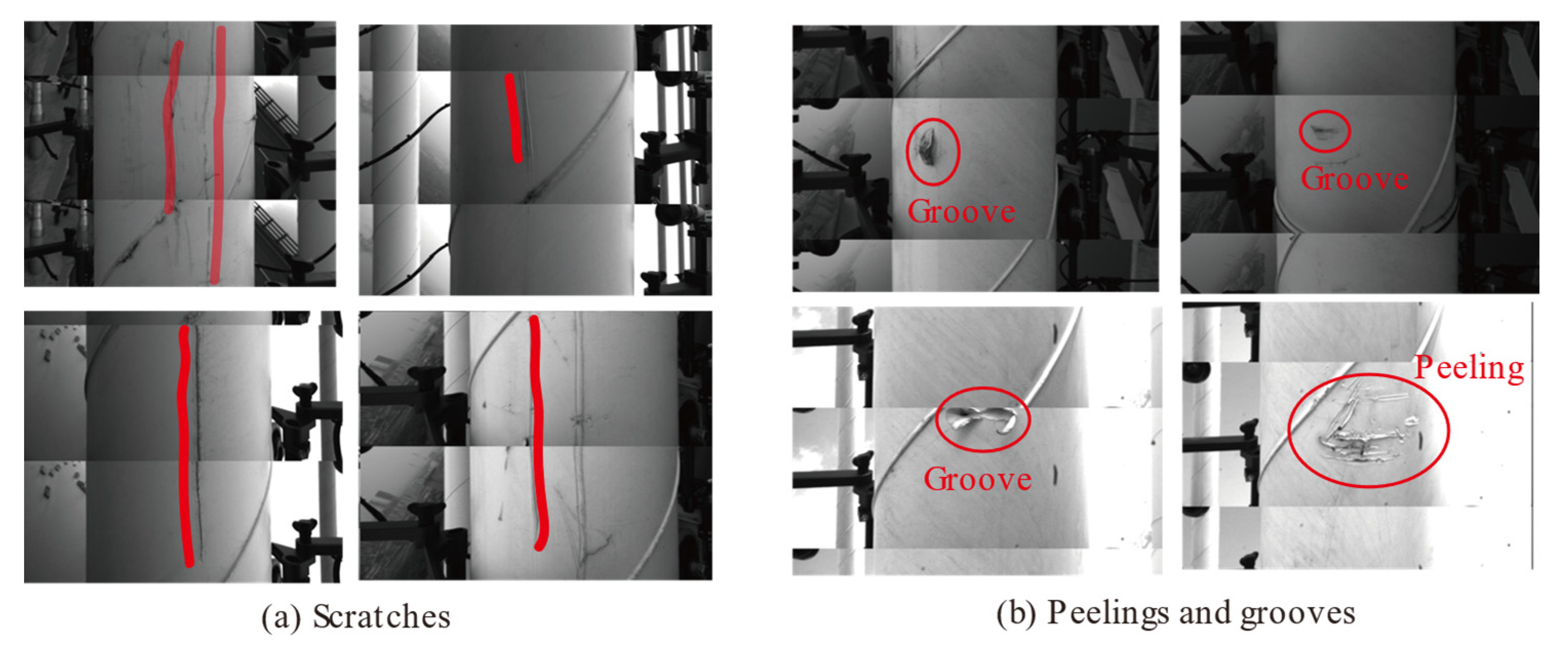
Over the past three decades, cable-stayed bridges have progressively emerged as one of the foremost designs for modern long-span bridges due to their esthetically pleasing structures and impressive load-bearing capabilities, thus finding widespread application worldwide. Cables are critical load-carrying components in cable-stayed bridges, exposed to natural environments for extended periods and subjected to high stress, making them vulnerable to damage such as sheath breakage, corrosion, and wire breakage [
1,
2]. Sheath breakage is one of the most frequently observed damage during inspections, often resulting from prolonged exposure to rain and sunlight [
3,
4]. After sheath breakage, the steel wires inside the cable are exposed to natural environments, accelerating the processes of corrosion and crack initiation [
5], ultimately leading to wire fracture [
6,
7]. Therefore, it is essential to develop effective surface defect detection methods for stay cables.
The traditional method for detecting cable surface defects is manual inspection, which primarily depends on visual assessment [
8]. Inspection personnel use telescopes and cameras with telephoto lenses to find the surface defects, a process that is time-consuming and imprecise due to constraints on observation positions. Another manual inspection method involves using ladder trucks or construction baskets to approach the cable surface for inspection and maintenance, which is inefficient and poses safety risks [
9,
10]. Due to these limitations, various alternative inspection methods have been proposed. Unmanned aerial vehicles (UAVs) exhibit promising potential for detecting surface defects due to their high mobility, capability to capture images of difficult-to-access components, and high efficiency [
11,
12]. While UAVs have been extensively utilized for inspecting bridge piers, decks and towers [
13,
14,
15,
16,
17], limitations arise when applying them to stay cables [
18]. Due to safe obstacle avoidance distance constraints, UAVs may not be able to approach the cable surface closely enough to capture precise images of defects or achieve a 360° field of view of stay cables. Currently, cable-climbing robots are among the most promising new approaches for detecting cable surface defects [
19,
20,
21]. These robots are designed to crawl along the stay cable, capturing high-resolution images with embedded cameras. By incorporating computer vision technology, cable surface defects can be automatically identified, significantly enhancing the efficiency of cable surface inspection [
6,
22,
23].
Several cable-climbing robots have been developed and utilized in cable stayed bridges [
24,
25] and suspension bridges [
26,
27] over the past decades. Advances in mechanical design have resulted in reduced self-weight, increased operation speed, and enhanced obstacle-overcoming capabilities [
28,
29,
30]. In addition to image acquisition devices, some robots are equipped with Non-Destructive Testing (NDT) devices. The magnetic flux leakage (MFL) method has proven to be an effective technique for detecting both uniform and pitting corrosion of steel wires inside cables [
31]. Such NDT devices have been integrated into cable-climbing robots [
25,
32], while their self-weight often exceeds the loading capacity of cable-climbing robots [
33], limiting their use in field tests. Meanwhile, cable repair devices [
34] have also been integrated into cable-climbing robots, which can automatically repair minor defects on cables. Despite automating the cable inspection process, the efficiency of these robots remains constrained by their operation speed, installation procedures, and adaptability to various cable diameters [
35]. Therefore, a cable-climbing robot with lightweight construction, rapid crawling speed, good encapsulation, and straightforward installation procedures is essential for field tests.
While many studies have focused on the mechanical design of cable-climbing robots, computer vision technology has also been extensively applied to defect recognition in civil structures [
36,
37]. Consequently, some research has explored the use of computer vision for automated cable defect detection. Ho et al. [
38] applied the Principal Component Analysis (PCA) method to evaluate the similarity between captured images and sample defect images. Li et al. [
39] developed a simplified scale-invariant feature transform (SIFT) algorithm for image mosaicking. Hou et al. [
40] employed concrete crack datasets through transfer learning to address the challenge of limited datasets for cable surface defect images. Xu et al. [
41] introduced an effective defect detection method by combining computer vision and diameter measurement. However, a comprehensive framework for cable surface defect recognition still requires further development to meet practical needs in cable inspections.
This study presents a lightweight intelligent robotic system with swift climbing capabilities and adaptability to various cable diameters. A defect recognition framework, based on computer vision technology, was developed to eliminate interference, identify defect regions, and automatically calculate defect geometry. Both laboratory and field tests were conducted to validate the system’s mechanical design and defect recognition capabilities. The rest of this paper is organized as follows:
Section 2 presents the mechanical design and key performance indicators of the proposed system.
Section 3 outlines the stages of the proposed defect recognition framework.
Section 4 discusses the implementation and results of laboratory and field tests conducted with the intelligent robotic system. Finally, conclusions are presented in
Section 5.
2. Mechanical Design of the Intelligent Robotic System
2.1. Overall Design
The main challenge in designing the intelligent robotic system is to adapt it to the complex service conditions of stay cables. These cables are cylindrical structures composed of multiple steel wires encased in polyethylene (PE) sheaths, whose surfaces often feature irregularities caused by defects or rain lines. Positioned at elevated locations, stay cables typically have inclination angles between 30° and 90° and diameters ranging from 70 to 270 mm. Moreover, vibrations induced by wind and traffic loads further complicate the robot’s stable operation.
To effectively address the challenges associated with cable inspections, the robotic system must exhibit the following characteristics: (1) a lightweight structure that allows for easy installation and adapts to various cable diameters, thereby improving inspection efficiency; (2) a driving mechanism with sufficient power to overcome its self-weight and any obstacles, ensuring stable and rapid climbing; (3) a high-resolution image acquisition module to support accurate automatic defect recognition.
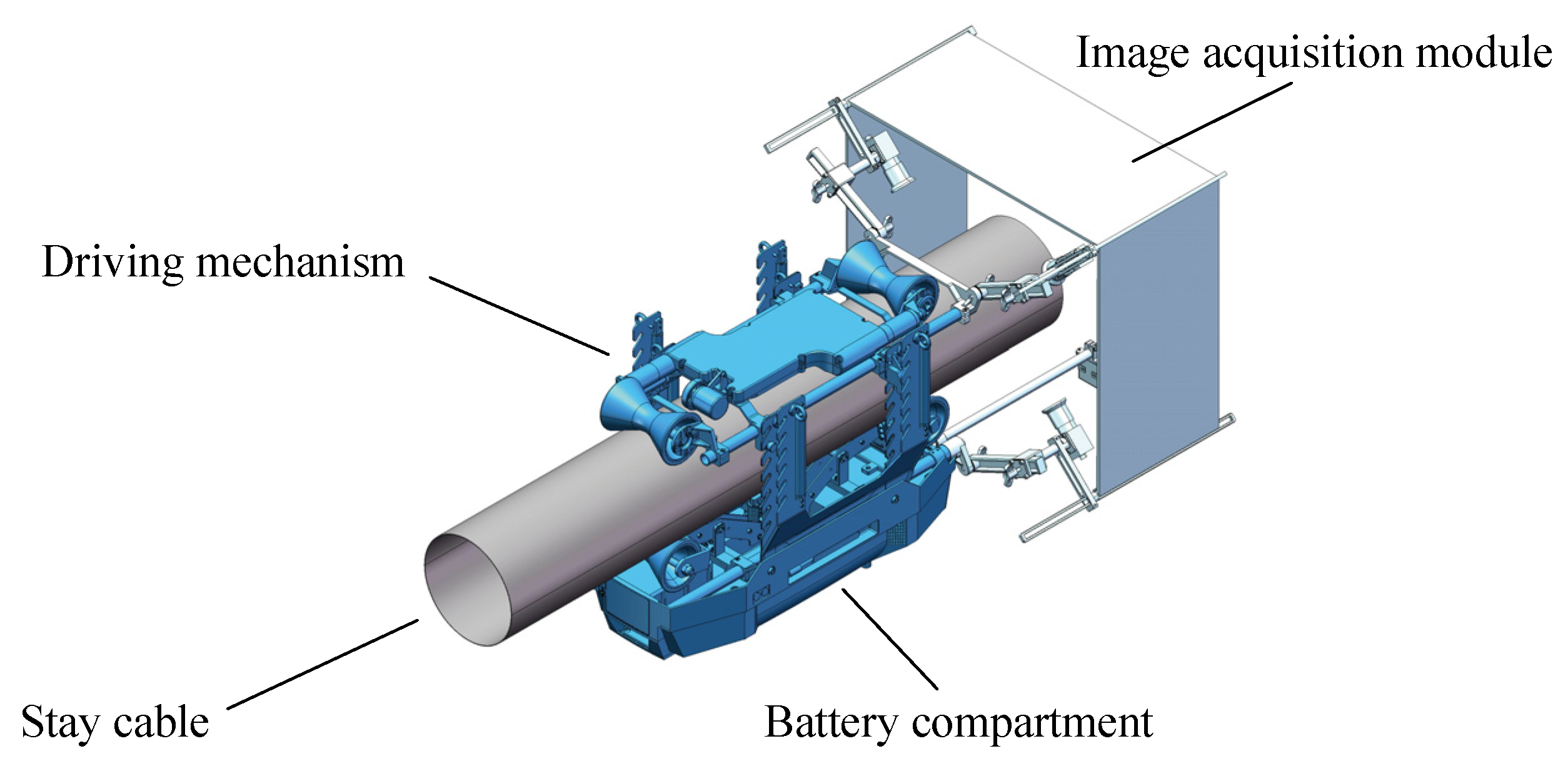
The proposed mechanical design of the intelligent robotic system consists of three main components: the driving mechanism, the image acquisition module and the battery compartment, as shown in
Figure 1. The driving mechanism includes two servo motor-driven power systems that provide the necessary force for ascent. The image acquisition module captures real-time data of the cable surface, which is used for subsequent image processing to automatically identify defects. The battery compartment is positioned at the lower section of the system to keep the center of gravity below the cable’s diameter, thereby preventing any shift or deflection during climbing. To reduce weight while maintaining strength, non-structural components are made of plastic, and parts of the structure are constructed from carbon fiber to ensure strength while simultaneously reducing weight. The key performance indicators of the proposed system are detailed in
Table 1.
2.2. Driving Mechanism
The driving mechanism is a crucial component that supports various sensors and controllers. It must have sufficient driving capacity to counteract its own weight and carry the load of the detection devices. Additionally, the mechanism must ensure the stability of the entire system, considering the cable vibrations caused by vehicles and wind, as well as the large inclination angles and deflection of the stay cable.
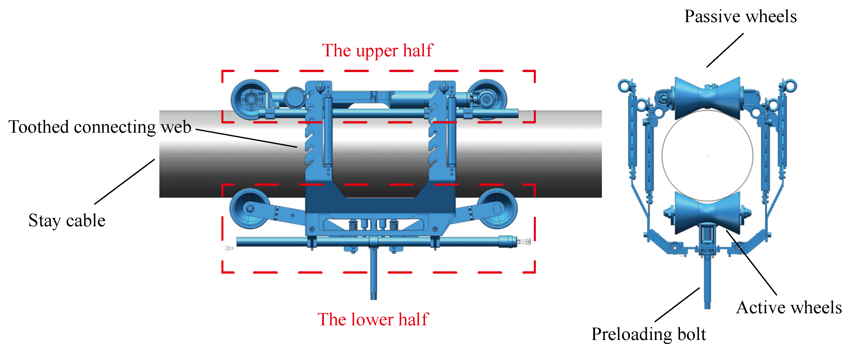
Therefore, as illustrated in
Figure 2, the driving mechanism employs a dual-wheel driving structure, composed of two active wheels and two passive wheels. The passive wheels are positioned above the stay cable, while the two active wheels, each driven by a servo motor, are positioned below. These active wheels, made of aluminum alloy and covered with rubber cladding, apply inward pressure on the stay cable through a preloading bolt, ensuring a secure grip and generating sufficient friction.
In order to analyze the stress state of the system during operation, the mechanical schematic is illustrated in
Figure 3. The driving force is provided by the friction between the active wheels and the stay cable:
where
represents the driving force,
denotes the friction between the active wheel and the stay cable,
denotes the friction coefficient,
denotes the normal force applied to the active wheel by cable surface,
denotes the total mass of the whole system and
denotes the inclination angle of the stay cable.
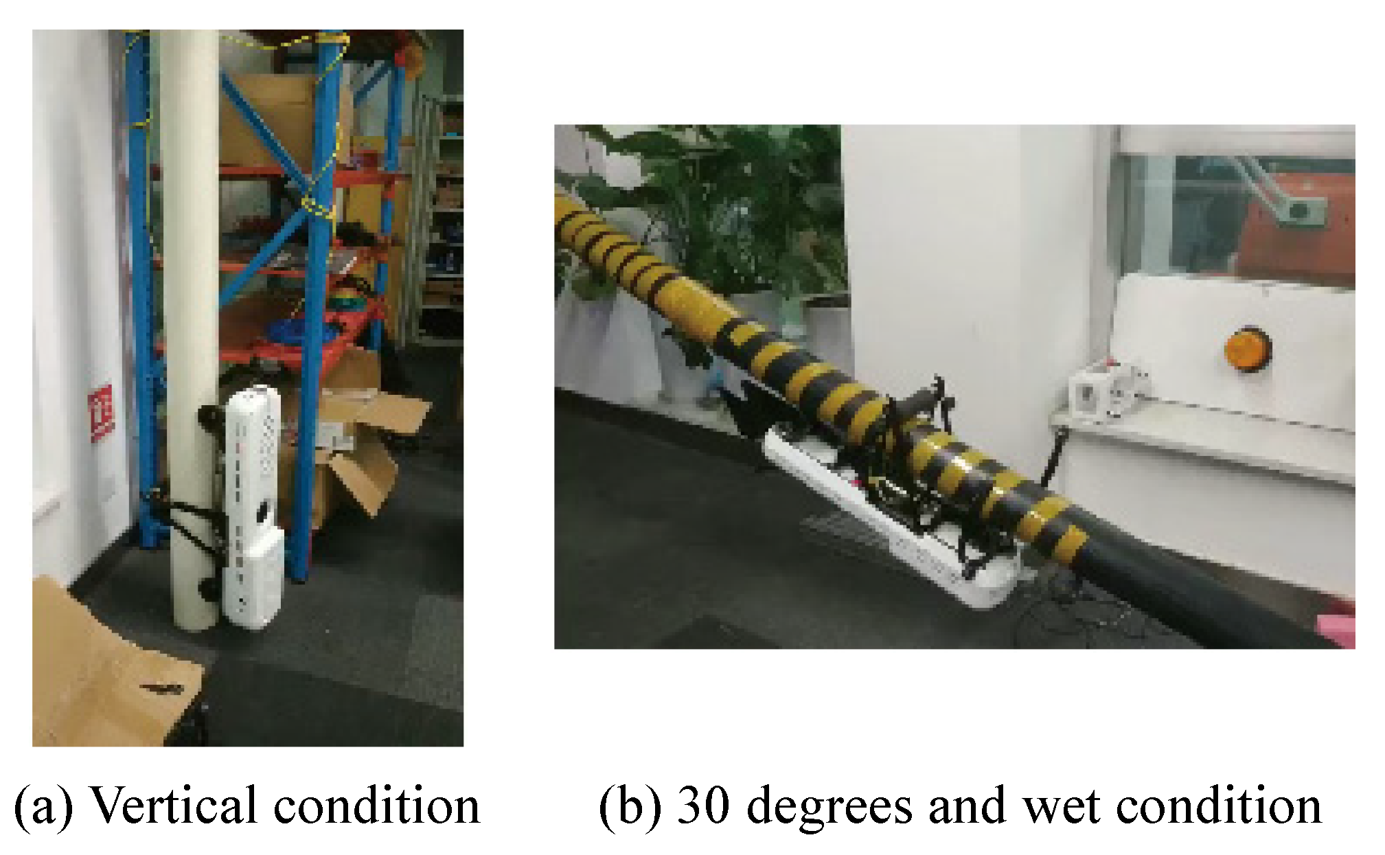
Under vertical working conditions (where ), considering a total system mass of 15 kg, and taking and a safety factor of 1.5, the required normal pressure is calculated to be 187 N. Furthermore, employing the principle of lever balance, the required spring force is calculated to require a pressure of 133 N to maintain equilibrium. Therefore, a spring with a maximum load of 422 N and a maximum deformation of 22 mm is chosen.
The robot’s obstacle negotiation capability relies on two key components: the spring and the soft silicone grease material coating the wheels. The spring’s elastic coefficient is calculated to be 19.2 N/mm, providing a spring force of 133 N under vertical working conditions, which allows for an additional 15 mm of deformation. Consequently, the robot’s maximum obstacle clearance is conservatively estimated to be 10 mm, sufficient to navigate rain lines and defects on the stay cable.
Adaptivity to various cable diameters is achieved by dividing the system into an upper half and a lower half, connected by a toothed web plate. The toothed web plate offers multiple locking positions, allowing adjustment for cable diameters ranging from 90 mm to 260 mm. Once the robot is installed on the cable, the preloading force exerted on the cable can be fine-tuned by rotating the preloading bolt, ensuring stable and reliable operation.
2.3. Image Acquisition Module
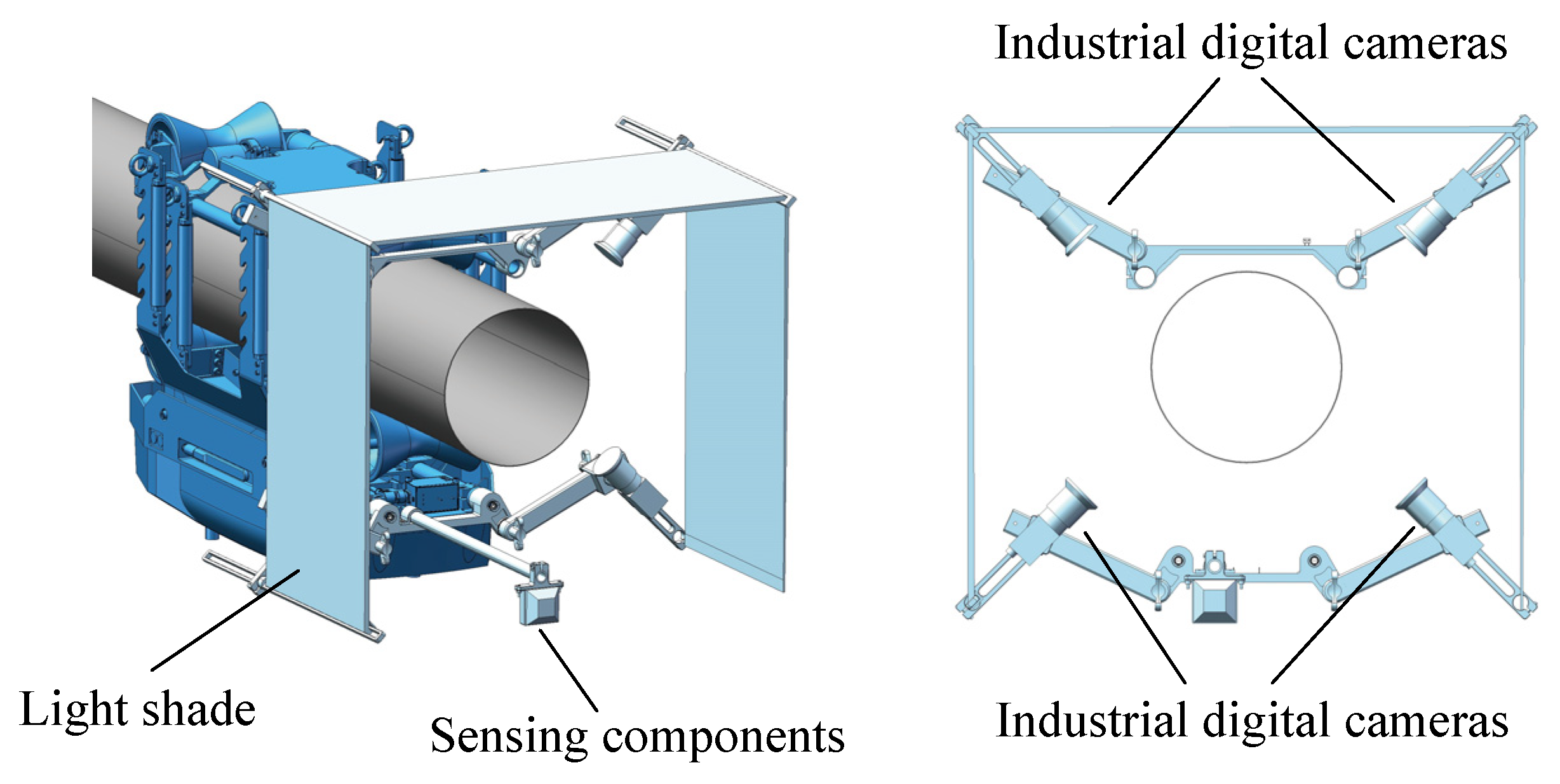
The image acquisition module, depicted in
Figure 4, captures the condition of the cable surface, enabling subsequent image processing for defect detection. Four industrial digital cameras are mounted radially around the cable, with adjustable positions to accommodate various cable diameters, ensuring full 360° coverage. Adjustable light shades are employed to counter direct sunlight by modifying their angles based on sunlight intensity and direction, thus ensuring uniform light distribution and significantly improving image quality. The sensing components include a displacement sensor and an obstacle avoidance sensor. The displacement sensor records the position of captured images, providing essential data for defect localization. This is accomplished by mounting an external rotary encoder on the drive wheels, which measures wheel rotation angle and speed, generating pulse signals proportional to the wheel revolutions. The microcontroller unit (MCU) processes these pulse signals to calculate the robot’s longitudinal displacement based on the known wheel diameter and circumference. The MCU also triggers the camera to capture images at predefined intervals of 0.15 m, ensuring uniformly spaced inspection data along the cable. Both odometry and image trigger signals are transmitted to the industrial computer, where each image is automatically associated with its corresponding displacement information. By combining encoder-based odometry data with image resolution and pixel size, the position of surface defects can be accurately determined, with a resolution of defect localization along the cable length approximately 0.01 m. The obstacle avoidance sensor, an ultrasonic device, enables the robot to automatically reverse upon detecting the surface of the bridge tower and terminate operation at a predetermined height above the bridge deck.
5. Conclusions
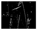
To address the problems of subjectivity, efficiency, cost and safety in cable surface inspection, an intelligent robotic system for cable surface defect detection was developed based on industrial robot technology and computer vision technology in this study. By utilizing carbon fiber materials and optimal structural design, the self-weight of this system has been reduced to 12 kg. The dual-wheel driving structure ensures sufficient climbing power, with the maximum climbing speed reaching 26 m/min under vertical conditions. The obstacle overcoming mechanism, inspired by the suspension structure of automobiles, adequately addresses obstacles such as rain lines and defects on the stay cable, with a maximum obstacle overcome capability exceeding 10 mm. Dividing the system into an upper and lower half connected by a toothed web achieves the adaptability of this system to cable diameters ranging from 90 mm to 260 mm.
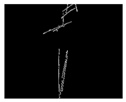
The captured cable surface images were processed through the proposed defect recognition framework. Combining histogram equalization, Gaussian filtering and Sobel edge detection, the Hough Line Detection Algorithm is able to accurately identify the sheath edges, thereby eliminating background information. Meanwhile, the NCC based template matching demonstrates superior performance in identifying rain lines. Finally, automatic calculation of defect geometry is achieved through connected domains and contour extraction. Both laboratory tests and field tests have verified the performance of the developed intelligent robotic system. Future work will focus on integrating deep learning methods into the inspection framework. With the accumulation of sufficient datasets, these methods are expected to enable more accurate identification and classification of cable surface defects.
