Article

Research on Optimization of Grouting Parameters for the CRD Method in Tunnels in Upper-Soft and Lower-Hard Composite Strata Based on Finite Element Method

1
China Railway (Guangzhou) Investment and Development Co., Ltd., Guangzhou 510308, China
2
China Railway 10th Bureau Group Urban Rail Transit Engineering Co., Ltd., Jinan 250001, China
3
School of Civil and Transportation Engineering, Guangdong University of Technology, Guangzhou 510006, China
4
Guangdong Wengu Testing and Appraisal Co., Ltd., Guangzhou 511453, China
5
School of Civil Engineering, Guangdong Communication Polytechnic, Guangzhou 510650, China
6
Guangdong Wisdom Cloud Engineering Technology Co., Ltd., Foshan 528000, China
*
Author to whom correspondence should be addressed.
Buildings 2025, 15(20), 3745; https://doi.org/10.3390/buildings15203745
Submission received: 10 September 2025 / Revised: 13 October 2025 / Accepted: 16 October 2025 / Published: 17 October 2025

Abstract

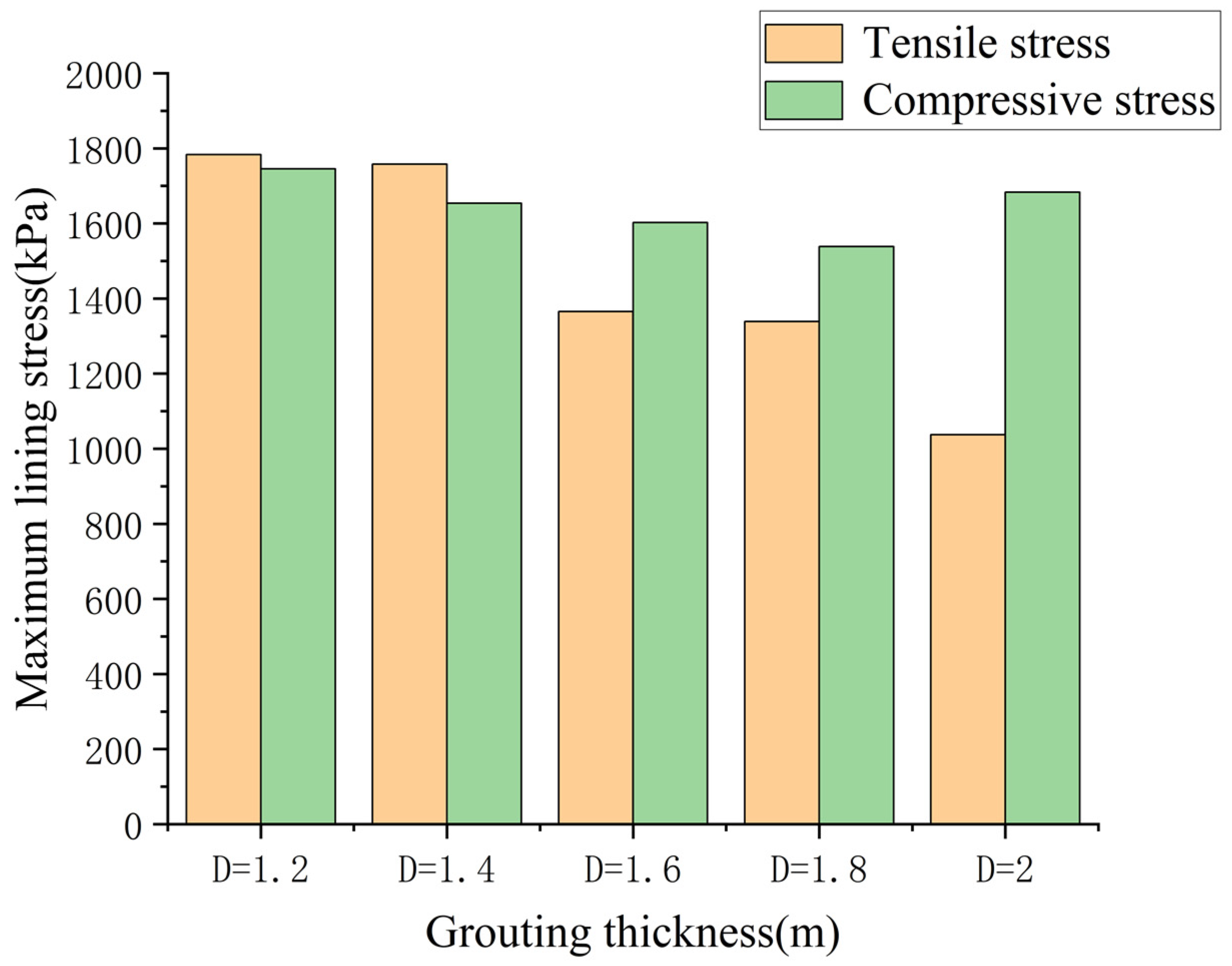
Tunnel excavation typically induces disturbance to the surrounding soil. Advance grouting using small-diameter pipes can effectively mitigate surface settlement. Taking the mine-method tunnel at the southern end of Xiancun Station on Guangzhou Rail Transit Line 18 as the research object, this paper uses the Midas GTS NX three-dimensional finite element (FE) software and adopts the upper-lower excavation method that prioritizes the formation of an upper support closed loop to simulate and analyze the impact of the CRD method on tunnel excavation under different grouting layer thicknesses. The research indicates that the surface settlement curve exhibits a “U”-shape. The settlement value decreases as the thickness of the grouting layer increases; when the thickness increases from 1.2 m to 2.0 m, the maximum surface settlement decreases from 12.87 mm to 9.09 mm, with successive reductions of 1.30 mm, 1.11 mm, 0.81 mm, and 0.56 mm, corresponding to rates of 10.10%, 9.59%, 7.67%, and 5.6%. Increasing the thickness of the grouting layer can effectively control surface settlement; however, when the thickness reaches 2.0 m, the stress distribution undergoes a change. Specifically, the compressive stress at the arch waist increases to 1683.01 kPa, and plastic failure occurs in the surrounding rock. By comparing the numerical results with field monitoring data, it is determined that when the grouting layer thickness is 1.4 m and the elastic modulus is increased by 30% based on that of the upper-soft soil, the model prediction shows the highest consistency with the actual effect. Furthermore, it is suggested that the grouting layer thickness be increased to 1.6 m. This study delivers a scientific foundation for the design of grouting parameters and the optimization of construction schemes for tunnels in composite strata and is of importance to improving tunnel construction technology in underground rail transit.

1. Introduction

Since the 21st century, with the advancement of China’s modern urban construction, the problems of limited urban land area and severe urban traffic congestion have become increasingly prominent. Consequently, the construction of underground rail transit has emerged as a crucial measure to alleviate urban traffic jams and optimize urban spatial layout [1,2,3]. Underground rail transit construction mainly consists of the construction of line tunnels and stations. However, as tunnel projects evolve toward greater depth, longer length, and larger cross-sections, the complexity of the construction environment has increased exponentially. Particularly in high-density urban built-up areas, tunnel construction faces numerous challenges [4].
A prevalent geological challenge in metro tunneling is the “upper-soft and lower-hard” composite stratum, where weak soils or weathered rock overlie competent bedrock in the tunnel profile [5,6,7]. Such strata are widely distributed in South China, East China, and other regions of China, and are frequently encountered in metro construction in cities such as Guangzhou, Shenzhen, and Nanjing [8,9]. These tunnel projects in the upper-soft and lower-hard composite strata are characterized by large span, large cross-sectional area, shallow burial depth, and complex geological conditions. Such geological conditions significantly complicate the construction of urban subway stations. Due to the existence of the soft–hard interface, there are significant differences in the failure mechanism between tunnels in single strata and those in upper-soft and lower-hard composite strata. The surrounding rock pressure borne by the tunnel support in the soft–hard interface stratum is unevenly distributed, and the support may undergo asymmetric deformation and develop cracks [10,11,12].
As a traditional excavation technology for underground engineering, the mining method has core advantages of high economy and strong geological adaptability. It can meet differentiated engineering requirements by flexibly adjusting construction parameters [13,14,15]. According to the excavation method and cross-sectional characteristics, the mining method is mainly divided into three categories: full-face method, bench method, and partial excavation method (such as CD method and CRD method). The CRD method (cross middle section method) excavation is a partial excavation method for weak surrounding rock or large-section tunnels [16,17]. After each step of excavation, the inverted arch is quickly closed to form multiple small, closed loops, thereby enhancing the overall stability. In practical engineering, the tunnel cross-section is divided into four small pilot tunnels. After the excavation of each pilot tunnel, steel arch frames are erected immediately, and shotcrete is applied to form temporary cross diaphragms with intersecting vertical and horizontal supports. Once the initial support of the full cross-section is stable, the cross diaphragms are removed in sections, and the secondary lining is constructed [18,19,20]. For the working condition simulated in this study, when the CRD method is used to excavate the tunnel in the composite stratum, the up-down excavation method that prioritizes the formation of the upper support closed loop is adopted. Specifically, the excavation sequence is ①-②-③-④, and the pilot tunnel numbers are depicted in Figure 1.
Recent years have witnessed a substantial scholarly focus on the efficacy of grouting reinforcement [21,22,23,24,25]. However, in practical engineering, the filling condition and reinforcement range of advanced small-pipe grouting reinforcement are still difficult to quantify [26,27]. With the rapid development of computers, finite element (FE) numerical simulation has become an important tool for design, construction, and risk assessment in tunnel engineering [28]. By reproducing the interaction between complex geology and structures through mathematical modeling, it provides a quantitative basis for engineering decision-making. At the same time, it is efficient and straightforward to adjust the test parameter settings, making it suitable for comparative analysis of a large number of working conditions with different construction parameters [29,30].
The author’s Gallig [31], Yun [32], and other scholars simulated the excavation and lining processes of shallow and deep tunnels based on 3D finite element models, and revealed the influence laws of soil parameters and excavation sequences on the deformation of the tunnel face and surface settlement; Yang [33], Wittaya [34], and others conducted a comparative study on the stability of elliptical tunnels in cohesive-frictional soils using the upper-bound FE method and verified the effectiveness of the new method in analyzing complex failure mechanisms. The author Hu [35] et al. simulated the entire failure process of tunnel crack initiation, propagation, and penetration under different confining pressures, and revealed the regulatory effect of confining pressure on the fracture mode; JH Chen [36] analyzed the freezing effect of the connecting passage through numerical simulation and on-site monitoring, and revealed that the surface displacement shows an “M”-shaped distribution. The author F Kitchah [37] analyzed the collapse accident of the T1 tunnel in Algeria through numerical simulation and proposed repair measures, such as increasing support stiffness; Yassaghi [38] analyzed the characteristics of extrusive rock at the contact zone of the Taloun tunnel through on-site monitoring and numerical simulation, providing theoretical guidance for the anti-extrusion support design of tunnels in similar geological conditions. Although numerous scholars have conducted extensive research on grouting reinforcement effects using finite element numerical simulation, studies focusing on the filling condition and reinforcement range of advanced small-pipe grouting in the CRD method in upper-soft and lower-hard composite strata remain limited. In particular, the quantitative relationship between grouting layer thickness and its impact on surface settlement, lining stress, and plastic zone development has not been systematically investigated for such composite geological conditions.
Taking the mining method tunnel at the southern end of Xiancun Station on Guangzhou Rail Transit Line 18 as the engineering background, this paper uses Midas GTS NX 2018 R1 software to establish a three-dimensional numerical model based on the FE analysis method. It studies the load response and deformation evolution characteristics of the surrounding rock-support system under different grouting layer thicknesses in the context of the up–down excavation method. This research can not only provide a scientific construction basis for the project but also contribute to enhanced construction safety and predictive control in comparable underground projects. Therefore, the present study carries substantial scientific implications and offers valuable insights for engineering applications.

2. Project Overview

Xiancun Station is an underground station, serving as the 8th station of Guangzhou Rail Transit Line 18 and an interchange station between Line 18 and Line 13. In accordance with the General Technical Requirements for Geotechnical Engineering Investigation of Guangzhou Rail Transit Network, and based on the engineering characteristics of the strata exposed along the line including geological age, genetic type, lithological features, and weathering degree the rock and soil layers at the site are divided into 8 major layers, with each major layer further divided into multiple sublayers according to specific stratum conditions. The mining method tunnel section in question is partially located in moderately to slightly weathered rock formations. The tunnel vault is situated in strongly to moderately weathered rock formations; locally distributed argillaceous siltstone is prone to disintegration when exposed to water. During excavation, the surrounding rock is susceptible to collapse and deformation. In shallowly buried sections, failures may propagate to the ground surface, which could result in tunnel collapse.
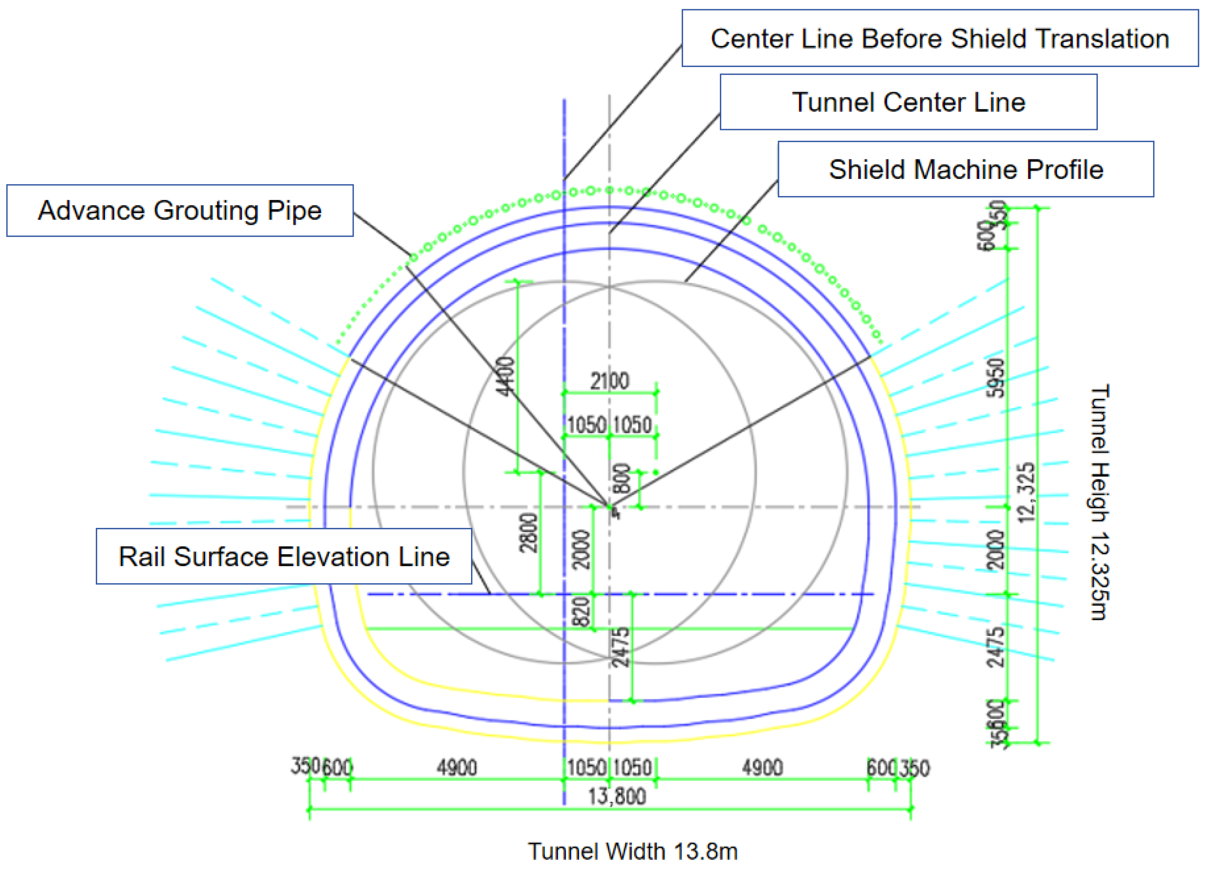
The mining method tunnel at the southern end is designed in accordance with the shallow-buried underground excavation method and adopts a composite lining structure. The initial support is a combination of multiple support types, including shotcrete, rock bolts, advanced small pipes, steel mesh, and section steel arch frames. Cast-in-place reinforced concrete forms the secondary lining, with a dedicated waterproof layer installed between the primary and secondary linings, as shown in Figure 2.

3. Establishment of the Numerical Model

GTS NX 2018 R1 (New experience of Geo-Technical Analysis System) is a general-purpose FE analysis software developed for the geotechnical field. It features functions such as 3D modeling, nonlinear material simulation, and dynamic construction stage analysis, enabling accurate simulation of complex geotechnical engineering problems, including tunnel excavation, slope stability, and foundation pit support. The software supports multi-physics field analysis (e.g., seepage–stress coupling and seismic dynamic response) and intuitively displays results such as displacement and plastic zones, which can meet the requirements of this numerical simulation [39,40]. Additionally, the FE simulation of tunnel excavation in the composite stratum involved in this study includes a large number of partial excavation procedures. The construction stage assistant in Midas GTS NX enables efficient setup and management of these construction stages.

3.1. Numerical Model Construction and Material Properties

The numerical model was configured according to the project’s actual geometry. The tunnel has a width of 13.8 m, a height of 12.325 m, and a buried depth of 15.95 m, with a total length of 40 m after completion of breakthrough. Therefore, the model dimensions are set to 80 m (length) × 40 m (width) × 60 m (height). According to previous studies [41,42] and comparisons with similar engineering cases, the grouting thickness at the vault of soft soil tunnels is mostly set to 1.2–2 m. In this simulation, five scenarios with grouting thicknesses of 1.2 m, 1.4 m, 1.6 m, 1.8 m, and 2 m are adopted to establish models for comparative analysis. Consistent with actual engineering conditions, the advanced small pipes were set at an external insertion angle of 10°, with a circumferential grouting range of 120°. Models with different grouting reinforcement layer thicknesses are shown in Figure 3a–e.
The 1D embedded truss elements are adopted to simulate rock bolts, and the 1D embedded beam elements are used to simulate grouting small pipes that can withstand bending to a certain extent. Meanwhile, the grouting reinforcement is simulated by employing the method of modifying soil parameters within the grouting range. Rock bolts were installed at the mid-span of the lining for each excavation cycle, and grouting small pipes were positioned at the tunnel face. In this model, the soil is treated as a discontinuous medium. For moderately weathered argillaceous siltstone and slightly weathered siltstone, the isotropic Mohr–Coulomb constitutive model is adopted for simulation [43], with 3D solid elements used. The initial support structure and the temporary support are modeled with an elastic constitutive model and simulated using 2D solid elements. The mesh around the tunnel was refined to 0.5 m, while a coarser mesh (up to 2 m) was used in regions far from the excavation to balance computational efficiency and accuracy.
According to previous studies on grouting reinforcement, the grouting reinforcement area is generalized as a homogeneous and uniform-thickness reinforcement material. Specifically, it forms a circular reinforced layer above the tunnel, which is referred to as the “equivalent layer” [44]. The equivalent layer is formed by the mixture of moderately weathered argillaceous siltstone from the upper stratum and cement mortar. Treated as an elastic material, its main parameters include Poisson’s ratio, elastic modulus, and thickness—all of which should fall between those of the soil mass and cement mortar [45]. The value of Poisson’s ratio has little impact on the stratum, so it is set to zero point two with reference to cement–soil. Grouting reinforcement via advanced small pipes can be regarded as an enhancement of surrounding rock properties; therefore, with reference to previous studies, the elastic modulus is increased by 30% based on that of moderately weathered argillaceous siltstone [46]. In this numerical simulation, the influence of the grouting effect on the stress redistribution of the surrounding rock-support system is studied mainly by changing the thickness of the equivalent layer. Additionally, the accurate thickness of the equivalent layer for this project is obtained through back analysis of field-measured surface settlement data. Based on the results of the geotechnical engineering investigation report, the physical and mechanical parameters of each material are determined, as shown in Table 1.

3.2. Boundary Conditions

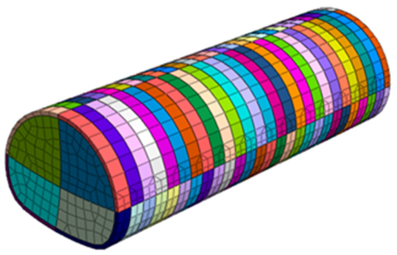
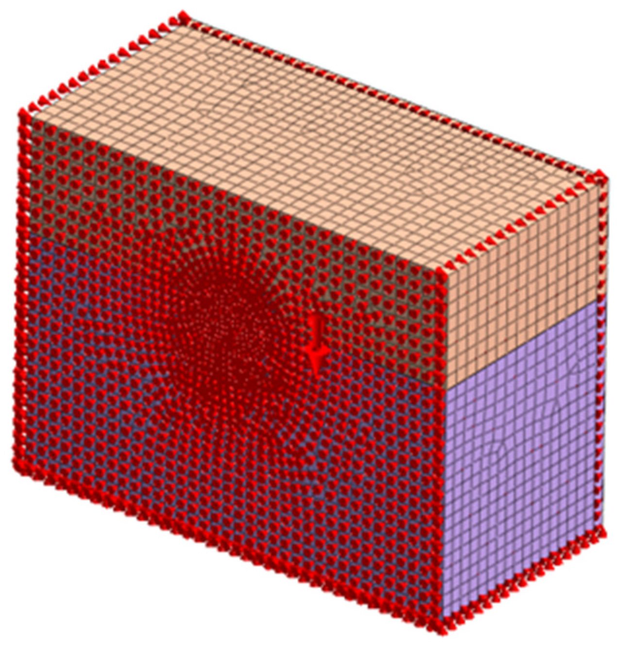
A tunnel model was established using the MIDAS GTS NX numerical FE analysis software, as shown in Figure 4. The setting of boundary conditions is intended to accurately reflect the surrounding environment of the tunnel and the mechanical characteristics of its boundaries, thereby ensuring the reliability and authenticity of the simulation results. To eliminate boundary effects, the surrounding soil of the tunnel should extend beyond twice the tunnel diameter. In the specific setting of boundary constraints, horizontal displacement restrictions (along the X-axis and Y-axis) are applied to all four side boundaries of the model, so as to reflect the inherent constraint state of the soil in the horizontal direction. The bottom boundary is set as fixed, while the displacement freedom in the vertical direction (along the Z-axis) is not restricted—this is to simulate both the constraint condition of the foundation soil and the actual behavior of the tunnel under load. For the top boundary, a fully free constraint condition is adopted without limiting its deformation, as shown in Figure 5.

3.3. Setting of Construction Stages and Analysis Conditions

According to the actual engineering conditions, the single excavation footage is set to 1.5 m, and the interval between excavation procedures is four excavation cycles—meaning the excavation interval between each pilot tunnel is 6 m. After the support of the lower–left pilot tunnel is completed, the temporary support is removed before proceeding with the excavation of the next cycle footage. The parameters of the grouting of small pipes and the grouting layer are activated every two construction footages, and the rock bolts installed within the pilot tunnel range are activated simultaneously when the pilot tunnel support is activated. The entire tunnel excavation consists of a total of seven excavation cycles, including 116 construction steps. The specific simulation steps are shown in Table 2.

4. Analysis of Simulation Results

4.1. Analysis of Surface Settlement

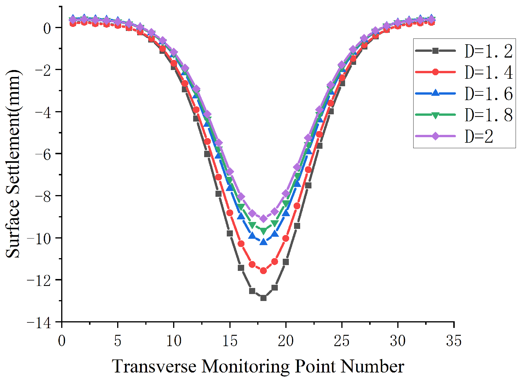
Following the actual monitoring layout, the final settlement values at horizontal monitoring points along Y = 5 m for various working conditions were extracted, as presented in Figure 6. For the surface settlement curve, the maximum final settlement value occurs directly above the vault; it gradually decreases toward both sides and shows a slight heave at the model boundary. The settlement trough exhibits a characteristic “U”-shape. When the thickness of the grouting layer is 1.2 m, the maximum surface settlement value is 12.87 mm; when the thickness is 2 m, the minimum surface settlement value is 9.09 mm. This demonstrates that the surface settlement decreases gradually with increasing grouting layer thickness. Meanwhile, during the process of increasing the grouting layer thickness from 1.2 m to 2.0 m, the maximum surface settlement decreases by 1.30 mm, 1.11 mm, 0.81 mm, and 0.56 mm. Compared with the adjacent interfaces, the decreases are 10.10%, 9.59%, 7.67% and 5.6%. During the process of uniformly increasing the thickness of the grouting layer, the surface settlement value changes significantly, which indicates that advanced small pipe grouting can effectively control surface settlement. At the same time, it is noted that the magnitude of the change in surface settlement value becomes increasingly smaller—this shows that after reaching a certain limit, the growth rate of the surface settlement control effect of grouting reinforcement will gradually weaken. In practical engineering, reasonable grouting parameters should be set according to the specific soil layer conditions.
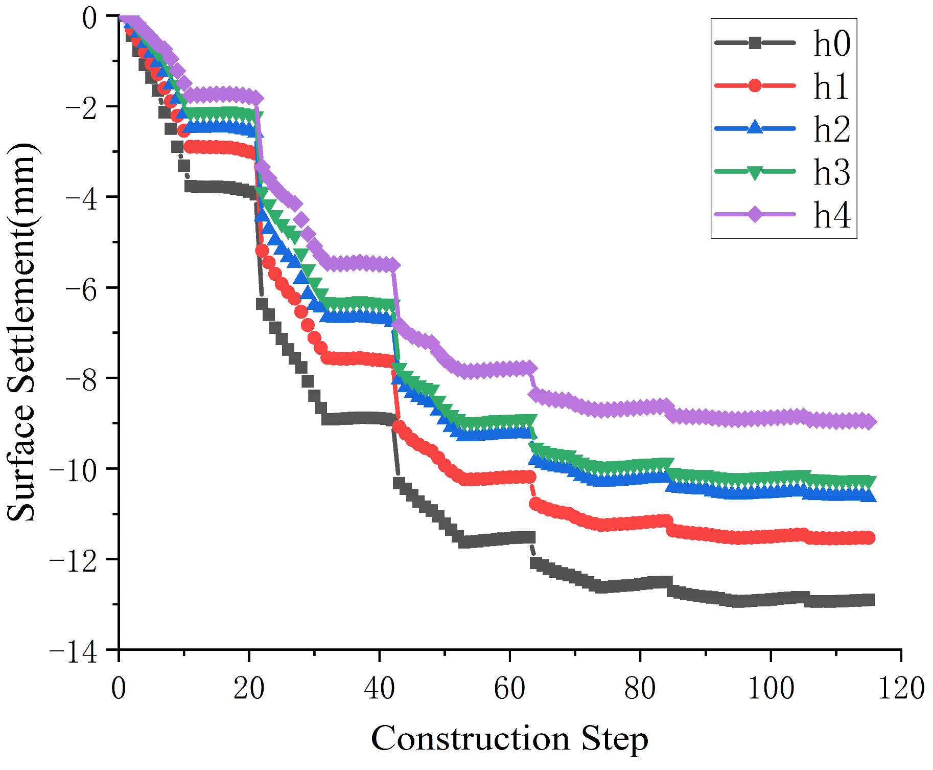
The variation of surface settlement with construction steps at the measuring point directly above the vault under five working conditions is extracted, as shown in Figure 7. Under the working conditions where the grouting layer thickness is 1.2 m, a total settlement of 4.62 mm occurs in one excavation cycle. Specifically, the settlement caused by the excavation of the upper pilot tunnel is 2.62 mm, accounting for 56.71%; the settlement caused by the excavation of the lower pilot tunnel is 0.13 mm, accounting for 2.81%; and the settlement caused by the removal of the temporary support is 1.87 mm, accounting for 40.48%. It can be seen that most of the settlement occurs during the excavation of the upper pilot tunnel and the removal of the temporary support. Under the supporting effect of the closed upper lining, the excavation of the lower pilot tunnel only causes a small amount of surface settlement. During the seven excavation cycles, settlement values of 4.62 mm, 4.71 mm, 2.01 mm, 1.02 mm, 0.34 mm, 0.14 mm, and 0.03 mm are generated. The settlement value increases slightly in the second cycle; in subsequent excavations, as the excavation face moves away from the surface measuring point, the disturbance to this location gradually decreases until the surface settlement stabilizes. This indicates that when the interval between pilot tunnel cyclic excavation procedures is 6 m, the excavation process of the cycle immediately below the measuring point has the greatest impact on stratum settlement.
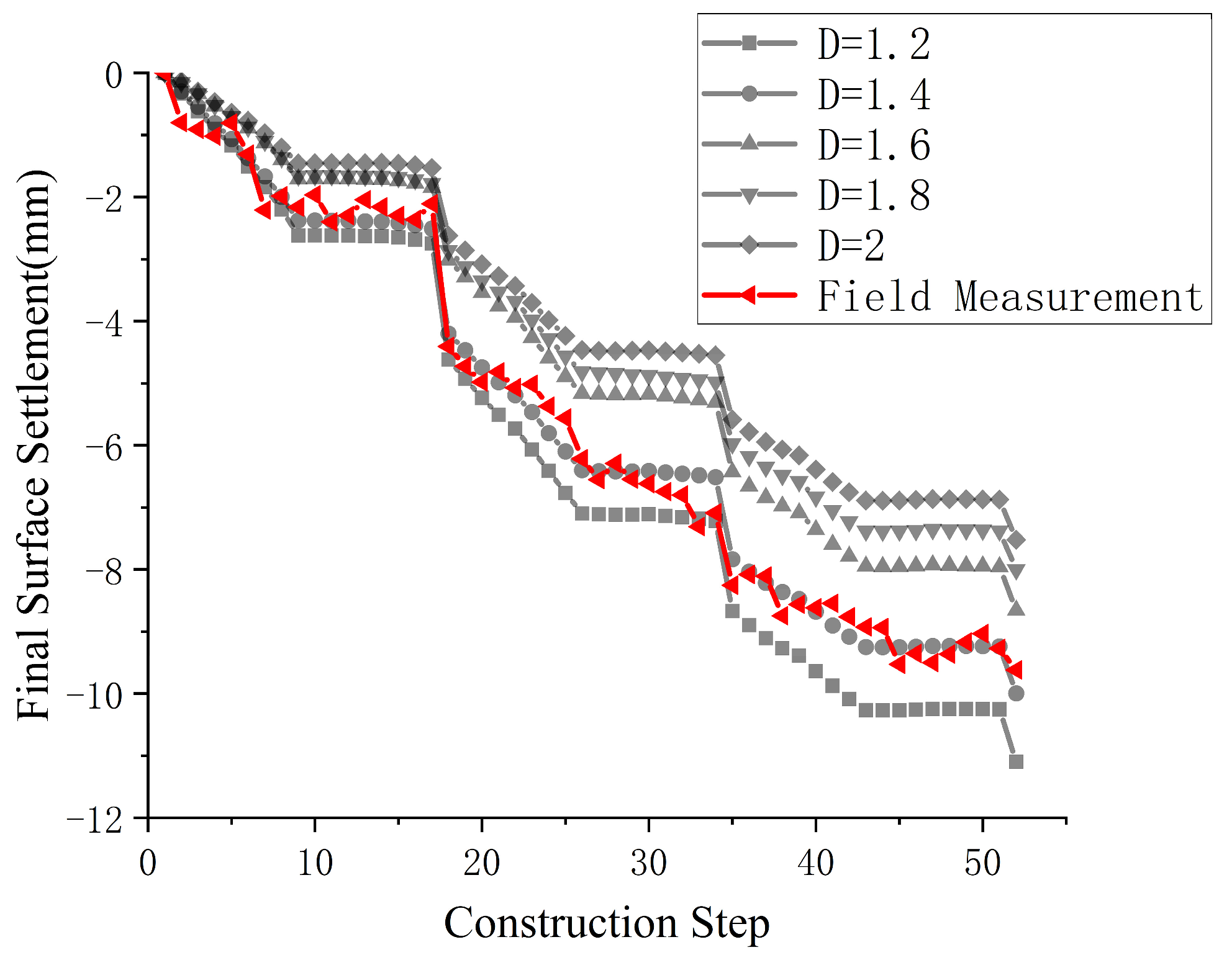
By comparing the surface settlement data obtained from on-site monitoring with those from numerical simulations under different grouting layer thicknesses, the parameters of the equivalent layer are derived with relatively high accuracy through the back-analysis method. The settlement data of the L2 monitoring point where the final surface settlement value is the maximum was selected for comparison with the settlement data of each working condition in the numerical simulation, as shown in Figure 8. From the comparison, it can be concluded that when the elastic modulus of the grouting layer is increased by 30% based on that of the upper-soft soil, the simulation result with a grouting layer thickness of 1.4 m is the closest to the on-site measured surface settlement data.

4.2. Analysis of Lining Stress

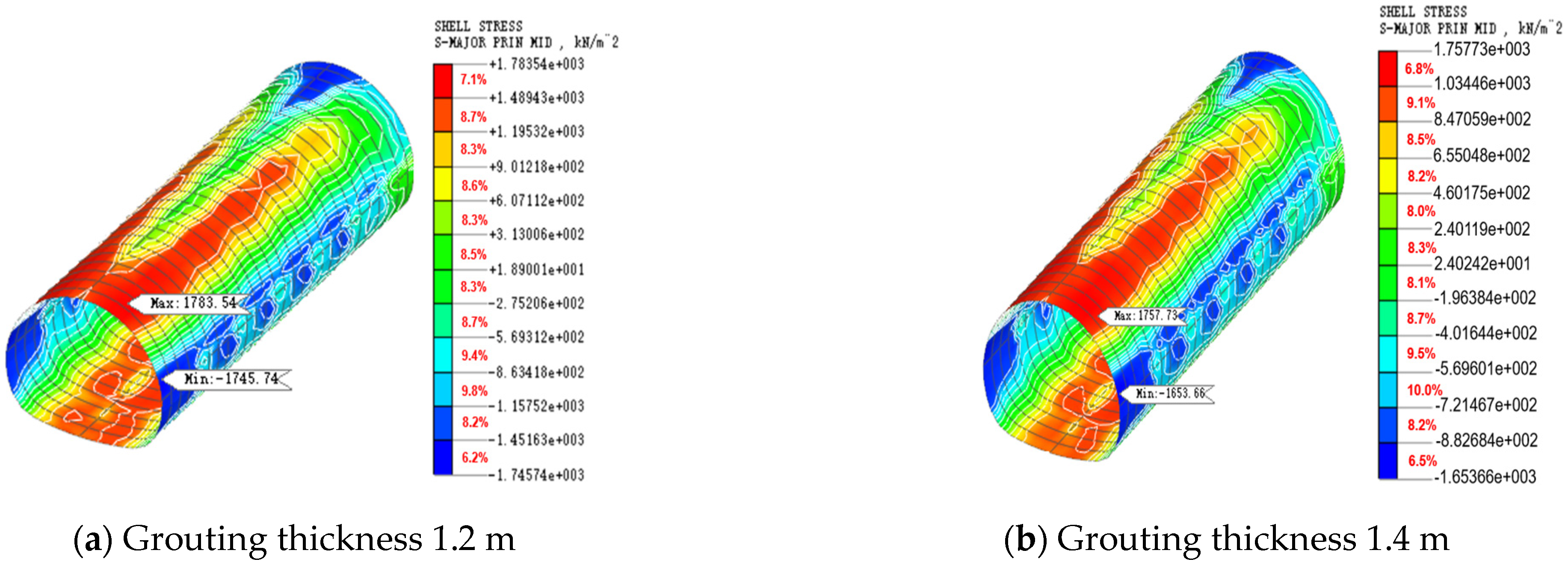
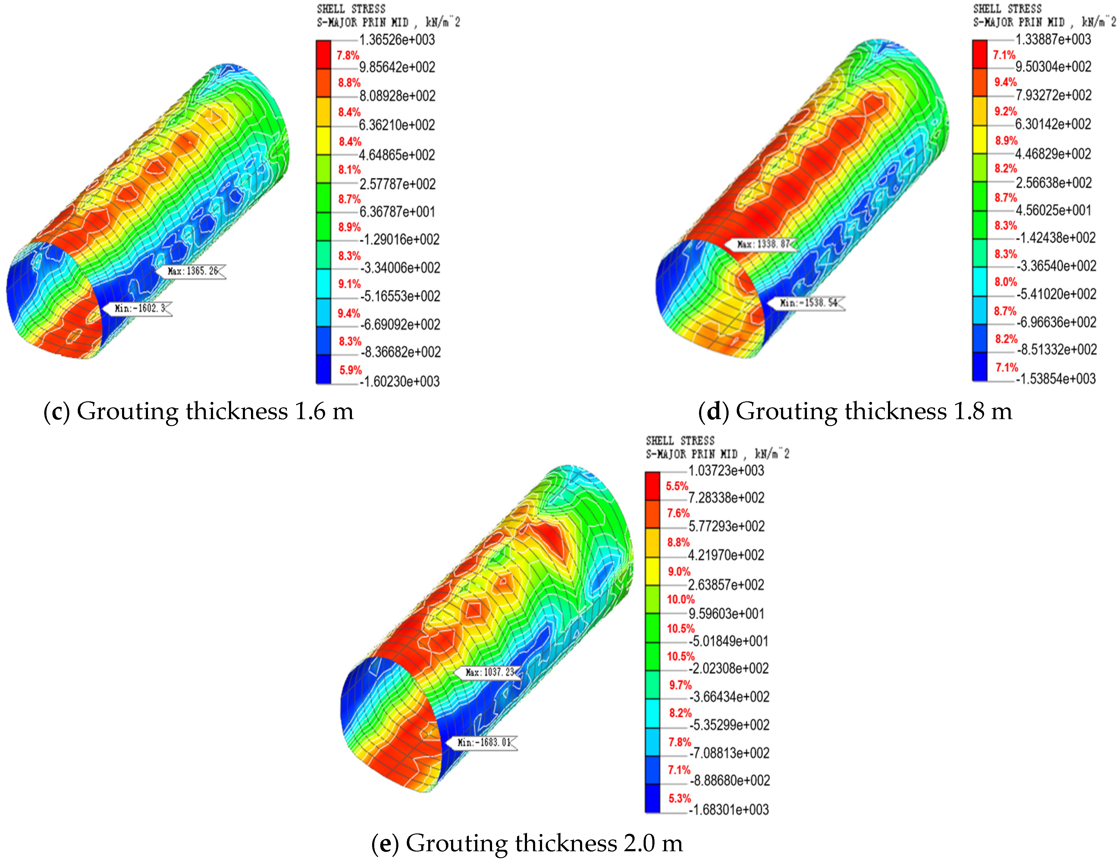
The stress nephograms of the support structure under various working conditions after tunnel excavation are shown in Figure 9. After the tunnel was driven 40 m and all temporary supports were removed, the overall stress state of the initial support presented a pattern of tension at the top and bottom, and compression on both sides. The maximum tensile stress occurs near the right side of the tunnel vault, while the maximum compressive stress is located at the right haunch. The initial support structure shows a slight rightward eccentric compression, but the overall stress distribution is relatively symmetric. Analysis of stress contour lines reveals a progressive attenuation of stress within the initial support structure along the longitudinal direction of the tunnel excavation. In other words, upon completion of the tunnel excavation, the main stress is concentrated in the front-middle part of the initial support structure.
The maximum stress values at various locations of the tunnel under working conditions with different grouting layer thicknesses are extracted, as shown in Figure 10. It can be seen from the bar chart that when the grouting layer thickness increases from 1.2 m to 1.8 m, both the maximum stress value at the upper end of the initial support structure and the maximum tensile stress value at the right haunch decrease gradually. This indicates that under the reinforcement effect of the advanced small pipes, the lithological properties of the soil in the grouting layer are enhanced, its self-stabilization capacity is significantly improved, and its load-bearing capacity is strengthened. Consequently, the load transmitted to the initial support structure below is reduced, which proves that the advanced small pipes have a good improvement effect on the stress concentration of the lining structure. Meanwhile, it is noted that when the grouting thickness increases to 2.0 m, although the maximum stress value at the upper end of the support further decreases to 1037.23 kPa, the maximum compressive stress value at the right haunch increases to 1683.01 kPa. This is because after the grouting layer thickness reaches a certain limit, the load cannot be effectively transmitted directly vertically downward; instead, most of the load spreads circumferentially along the grouting layer and is finally transmitted to the tunnel haunch. This, in turn, leads to a significant increase in the compressive stress at the haunch and makes the overall stress distribution of the support structure more uneven. This shows that the relationship between the grouting layer thickness and its improvement effect on the stress of the support structure is not a linear increase. In practical engineering, the most reasonable grouting parameters should be selected by comprehensively considering the maximum stress value of the support structure and the uniformity of the overall stress distribution.

4.3. Comparative Analysis of Surrounding Rock Plastic Zones

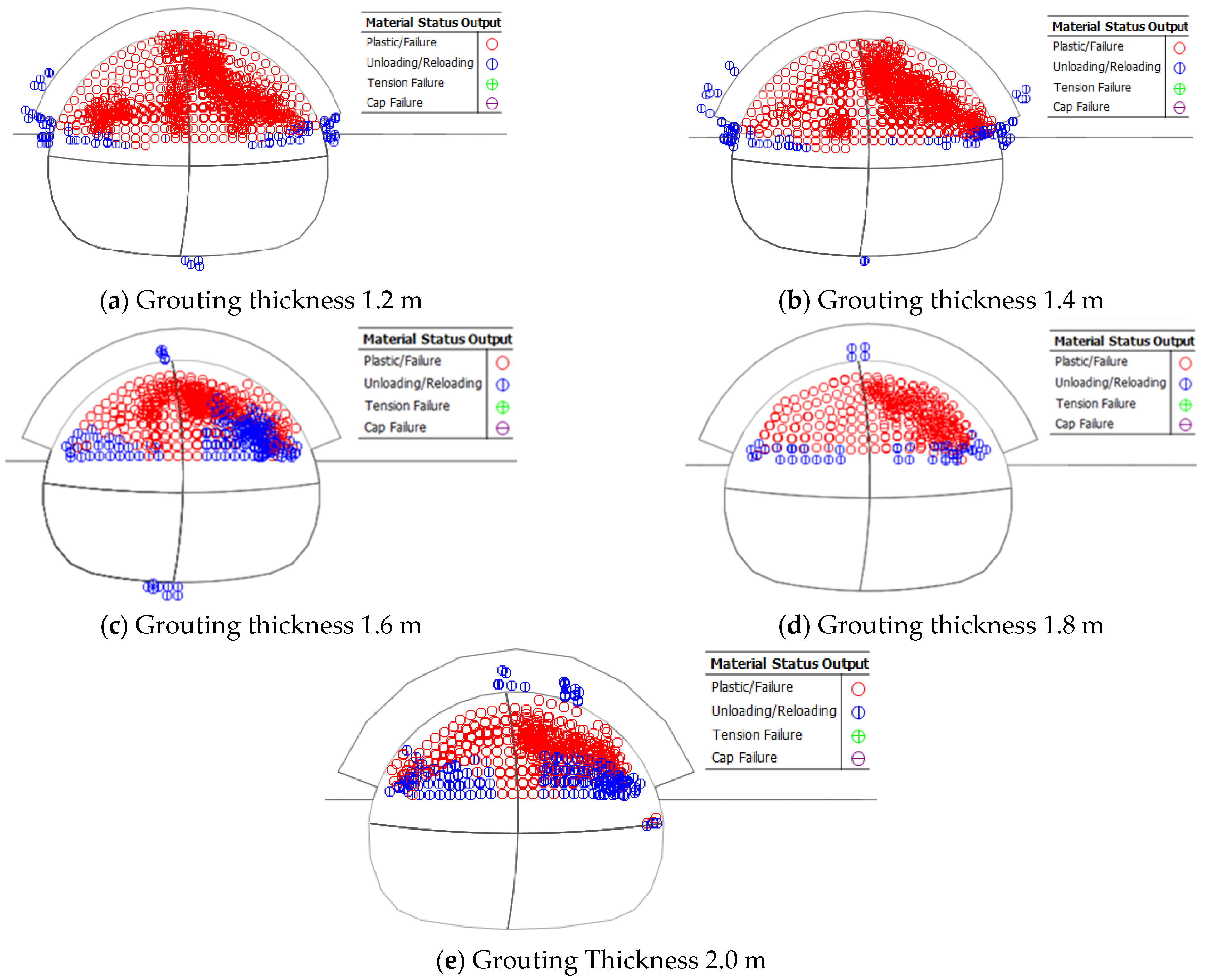
The distribution of the surrounding rock plastic zone around the tunnel excavation face under each working condition after the completion of the third excavation cycle is extracted, as shown in Figure 11a–e. Through the Solid Stresses (Solid Element Stress)-PLASTIC STATUS (Plastic State) module in Midas GTS NX, the distribution of the surrounding rock plastic zone can be visualized. In the resultant plot, red denotes areas that have undergone plastic failure, whereas blue indicates zones where failure is impending. It can be observed that the plastic zone is mainly distributed in the upper-soft soil within the range of the tunnel excavation face, bounded by the interface between soft and hard strata, and there is basically no plastic zone in the lower-hard soil. It can be observed that the plastic zone is mainly distributed in the upper-soft soil within the range of the tunnel excavation face, bounded by the interface between soft and hard strata, and there is basically no plastic zone in the lower-hard soil. In the upper-soft soil, the plastic failure in the areas close to the stratum interface is relatively slight; the farther upward from the soft–hard stratum interface, the more obvious the plastic development. There is no plastic zone in the surrounding rock above the grouting reinforcement layer. The advanced small pipe grouting reinforcement has effectively restricted the development of the plastic zone, so the most densely distributed plastic zone is located in the upper-middle part of the upper pilot tunnel excavation face.
As the thickness of the grouting layer increases, it can be clearly observed that the proportion of the blue area near the interface between soft and hard strata gradually increases, while the dense red area gradually decreases. This indicates that the increase in grouting reinforcement thickness can effectively enhance the stability of the tunnel surrounding rock and restrict the development of the plastic zone. At the same time, it should be noted that when the grouting layer thickness reaches 2.0 m, plastic failure of the surrounding rock occurs at the right haunch, a location where there was originally no plastic zone. This is consistent with the previously analyzed results of the lining stress; when the grouting thickness exceeds a certain limit, most of the load spreads circumferentially along the grouting layer, which instead leads to the occurrence of plastic failure at the haunch located in the lower-hard soil, where such failure did not exist before.

5. Conclusions

Motivated by the mine tunnel at the southern end of Xiancun Station on Guangzhou Metro Line 18, this study focuses on the tunnel excavation issue in composite strata. Through the application of numerical simulation, it investigates the surface settlement law, the response characteristics of the lining structure, and the surrounding rock stress state under the top-down excavation sequence of the CRD method (center diaphragm method), where the upper support closure is prioritized. Moreover, this research clarifies grouting parameters, elucidates the synergistic mechanism between the surrounding rock and the lining system in composite strata, and provides optimization for the engineering construction scheme. The principal findings of this study can be summarized as follows:
(1) The surface settlement curve reaches its maximum value directly above the vault, decreases gradually toward both sides, and shows slight heaving at the model boundary, presenting an overall “U”-shape. As the grouting thickness increases from 1.2 m to 2.0 m, the maximum surface settlement decreases by 10.10%, 9.59%, 7.67%, and 5.6%, respectively, indicating a diminishing rate of reduction. This indicates that the effectiveness of grouting reinforcement in controlling surface settlement diminishes beyond a certain thickness.
(2) The advanced grouting of small pipes can effectively control surface settlement, and their effect enhances with the increase of grouting layer thickness, but the growth is nonlinear. When the thickness increases from 1.2 m to 2.0 m, the maximum surface settlement value decreases by 10.10%, 9.59%, 7.67%, and 5.6% in sequence. Although increasing the grouting layer thickness generally enhances surrounding rock stability and suppresses plastic zone development, a thickness of 2.0 m induces circumferential stress redistribution towards the haunch. This leads to a substantial rise in compressive stress within the haunch lining, as well as the initiation of plastic failure in the adjacent surrounding rock. Therefore, in practical engineering, it is necessary to balance settlement control and structural bearing capacity to select the optimal grouting parameters.
(3) A comparison between the simulated settlement at monitoring point L2 (under five grouting thicknesses) and field-measured data revealed that the grouting reinforcement effect most closely matches the actual project performance when the grouting layer has an elastic modulus increased by 30% relative to the upper-soft soil and a thickness of 1.4 m.
The findings of this study are inherently limited by the adopted modeling approach. The constitutive models, including the Mohr–Coulomb criterion for geological materials and the idealized homogeneous ‘equivalent layer’ representing the grouted zone, may inadequately represent the inherent complexity and potential anisotropy of the upper-soft and lower-hard composite strata. Furthermore, the numerical model was validated primarily against surface settlement data, and its predictive accuracy for internal force distributions lacks direct confirmation from stress measurements within the support structure. Finally, the analysis omitted the influence of pore water pressure and time-dependent effects such as material creep, which could influence the long-term mechanical response. In the future, we will focus on these points for research.

Author Contributions

Writing—original draft, G.G.; Conceptualization, L.W.; Data curation, D.Z. and Y.L.; Project administration, J.L. and G.G.; Software, R.L. and J.L.; Resources, Y.L. and D.Z.; Methodology, H.L. (Hongzhong Li) and B.Y.; Validation, H.L. (Huifen Liu); writing-review and editing, B.Y.; Formal analysis, L.W.; Supervision, R.L.; Visualization, Y.L.; Investigation, H.L. (Hongzhong Li); Funding acquisition, H.L. (Huifen Liu) and B.Y. All authors have read and agreed to the published version of the manuscript.

Funding

This research was funded by The National Natural Science Foundations of China (No. 52278336 and 51978177), Guangdong Basic and Applied Research Foundations (No. 2023B1515020061 and 2022A1515240037) and Key Scientific Research Platform Projects of Guangdong Provincial Colleges and Universities (NO. 2024GCZX023; 2023CJPT003).

Data Availability Statement

The original contributions presented in this study are included in the article. Further inquiries can be directed to the corresponding author.

Conflicts of Interest

Authors Guixi Guo, Lei Wan and Deming Zhang were employed by the company China Railway (Guangzhou) Investment and Development Co., Ltd. Author Jin Li was employed by the company China Railway 10th Bureau Group Urban Rail Transit Engineering Co., Ltd. Author Yaojian Long was employed by the company Guangdong Wengu Testing and Appraisal Co., Ltd. Author Huifen Liu was employed by the company Guangdong Wisdom Cloud Engineering Technology Co., Ltd. The remaining authors declare that the research was conducted in the absence of any commercial or financial relationships that could be construed as a potential conflict of interest.

References

  1. Zacharias, J.; Tang, Y. Restructuring and Repositioning Shenzhen, China’s New Mega City. Prog. Plan. 2010, 73, 209–249. [Google Scholar] [CrossRef]
  2. Yuan, B.; Huang, X.; Huang, Q.; Shiau, J.; Liang, J.; Zhang, B.; Zheng, J.; Fahimizadeh, M.; Sabri, M.M. Effects of Particle Size on Properties of Engineering Muck-Based Geopolymers: Optimization through Sieving Treatment. Constr. Build. Mater. 2025, 492, 142967. [Google Scholar] [CrossRef]
  3. Shi, J.; Wang, J.; Chen, Y.; Shi, C.; Lu, H.; Ma, S.; Fan, Y. Physical Modeling of the Influence of Tunnel Active Face Instability on Existing Pipelines. Tunn. Undergr. Space Technol. 2023, 140, 105281. [Google Scholar] [CrossRef]
  4. Feature Fusion Method for Rock Mass Classification Prediction and Interpretable Analysis Based on TBM Operating and Cutter Wear Data. Tunn. Undergr. Space Technol. 2025, 157, 106351. [CrossRef]
  5. Wang, J.; Huo, Q.; Song, Z.; Zhang, Y. Study on Adaptability of Primary Support Arch Cover Method for Large-Span Embedded Tunnels in the Upper-Soft Lower-Hard Stratum. Adv. Mech. Eng. 2019, 11, 1687814018825375. [Google Scholar] [CrossRef]
  6. Lv, J.; Lin, D.; Wu, W.; Huang, J.; Li, Z.; Fu, H.; Li, H. Mechanical Responses of Slurry Shield Underpassing Existing Bridge Piles in Upper-Soft and Lower-Hard Composite Strata. Buildings 2022, 12, 1000. [Google Scholar] [CrossRef]
  7. Shi, L.; Zhou, H.; Song, M.; Lu, J.; Liu, Z. Geomechanical Model Test for Analysis of Surrounding Rock Behaviours in Composite Strata. J. Rock Mech. Geotech. Eng. 2021, 13, 774–786. [Google Scholar] [CrossRef]
  8. Lu, D.; Liang, J.; Du, X.; Ma, C.; Gao, Z. Fractional Elastoplastic Constitutive Model for Soils Based on a Novel 3D Fractional Plastic Flow Rule. Comput. Geotech. 2019, 105, 277–290. [Google Scholar] [CrossRef]
  9. Liu, C.; Zhang, S.; Zhang, D.; Zhang, K.; Wang, Z. Model Tests on Progressive Collapse Mechanism of a Shallow Subway Tunnel in Soft Upper and Hard Lower Composite Strata. Tunn. Undergr. Space Technol. 2023, 131, 104824. [Google Scholar] [CrossRef]
  10. Lv, J.; Li, X.; Fu, H.; Tang, Y.; Li, Z.; Zhao, H. Influence of Shield Tunnel Construction on Ground Surface Settlement under the Condition of Upper-Soft and Lower-Hard Composite Strata. J. Vibroeng. 2020, 22, 1126–1144. [Google Scholar] [CrossRef]
  11. Yuan, B.; Huang, Q.; Xu, W.; Han, Z.; Luo, Q.; Chen, G.; Yuan, J.; Zhang, Q.; Sabri, S.M.M. Study on the Interaction between Pile and Soil under Lateral Load in Coral Sand. Geomech. Energy Environ. 2025, 42, 100674. [Google Scholar] [CrossRef]
  12. Zhang, X.; Song, Q.; Yao, Z.; Su, D.; Zhang, Y.; Li, Q. Limit Equilibrium Models for Tunnel Face Stability in Composite Soft-Hard Strata. Appl. Sci. 2023, 13, 10748. [Google Scholar] [CrossRef]
  13. Zhang, L.; Pan, Y.; Chen, K.; Zheng, G.; Gao, Y.; Chen, P.; Zhong, G.; Chen, P.; Xu, F.; Zhang, Y.; et al. The Effect of CRD Method and Auxiliary Construction on Surface Settlement in Shallow-Buried Tunnels. Front. Earth Sci. 2023, 10, 998717. [Google Scholar] [CrossRef]
  14. Han, Y.; Wei, C.; Cui, M.; Xie, H.; Ou, Y.; Zhu, H.; Liu, T. Ground Settlement of Deeply Buried Two-Lane Tunnels with Large Cross-Sections Using Different Construction Methods. Appl. Sci. 2022, 12, 11105. [Google Scholar] [CrossRef]
  15. Ren, Y.; Zhou, S.; Jia, J.; Yuan, Q.; Liu, M.; Song, S.; Zhou, Z.; Wang, Z. The Influence of Construction Methods on the Stability of Tunnels and Ground Structures in the Construction of Urban Intersection Tunnels. Sustainability 2023, 15, 14720. [Google Scholar] [CrossRef]
  16. Li, S.; Zhang, Y.; Cao, M.; Wang, Z. Study on Excavation Sequence of Pilot Tunnels for a Rectangular Tunnel Using Numerical Simulation and Field Monitoring Method. Rock Mech. Rock Eng. 2022, 55, 3507–3523. [Google Scholar] [CrossRef]
  17. Liu, W.; Chen, J.; Chen, L.; Luo, Y.; Shang, Q.; Zhang, L.; Gao, S.; Jia, H. A Rational Construction Method and Deformation Control System of Tunnelling in Extremely Soft and Fractured Chlorite Schist Medium. Tunn. Undergr. Space Technol. 2024, 143, 105472. [Google Scholar] [CrossRef]
  18. Ren, Y.; Zhou, S.; Jia, J.; Yuan, Q.; Zhou, Z.; Liu, M.; He, H. Construction Stability Analysis of Intersection Tunnel in City under CRD Method. Front. Earth Sci. 2023, 11, 1264140. [Google Scholar] [CrossRef]
  19. Wang, Z.; Yao, W.; Cai, Y.; Xu, B.; Fu, Y.; Wei, G. Analysis of Ground Surface Settlement Induced by the Construction of a Large-Diameter Shallow-Buried Twin-Tunnel in Soft Ground. Tunn. Undergr. Space Technol. 2019, 83, 520–532. [Google Scholar] [CrossRef]
  20. Shi, J.; Zhong, X.; Lu, H.; Ni, X.; Shi, C. Influence of Joint Stiffness on Three-Dimensional Deformation Mechanisms of Pipelines under Tunnel Active Face Instability. Can. Geotech. J. 2025, 62, 1–18. [Google Scholar] [CrossRef]
  21. Yuan, B.; Liang, J.; Zhang, B.; Chen, W.; Huang, X.; Huang, Q.; Li, Y.; Yuan, P. Optimized Reinforcement of Granite Residual Soil Using a Cement and Alkaline Solution: A Coupling Effect. J. Rock Mech. Geotech. Eng. 2025, 17, 509–523. [Google Scholar] [CrossRef]
  22. Lu, D.; Zhou, X.; Du, X.; Wang, G. A 3D Fractional Elastoplastic Constitutive Model for Concrete Material. Int. J. Solids Struct. 2019, 165, 160–175. [Google Scholar] [CrossRef]
  23. Yuan, B.; Huang, X.; Li, R.; Luo, Q.; Shiau, J.; Wang, Y.; Yuan, J.; Muayad Sabri, S.M.; Huang, S.; Liao, C. Dynamic Behavior and Deformation of Calcareous Sand under Cyclic Loading. Soil Dyn. Earthq. Eng. 2025, 199, 109730. [Google Scholar] [CrossRef]
  24. Lu, H.; Qiu, J.; Kong, X.; He, Z. Experimental Study on Temperature Characterization during Cement Grouting Reinforcement. Case Stud. Therm. Eng. 2023, 41, 102577. [Google Scholar] [CrossRef]
  25. Lou, P.; Huang, W.; Huang, X. Analysis of Shield Tunnels Undercrossing an Existing Building and Tunnel Reinforcement Measures. Appl. Sci. 2023, 13, 5729. [Google Scholar] [CrossRef]
  26. Wang, X.; Li, Z.; Li, W.; He, C.; Wang, Z. Analysis and Prediction of Dynamic Stress Concentration in Jointed Coal Using Boundary Element Method. Theor. Appl. Fract. Mech. 2025, 140, 105136. [Google Scholar] [CrossRef]
  27. Cheng, W.; Zhu, C.; Shi, G.; Liu, Z.; Liu, C.; Du, Y.; Chen, Y.; Zhuang, C.; Gu, H. Effect of Grouting, Concrete Cover, and Combined Reinforcement on Masonry Retaining Walls. Buildings 2025, 15, 309. [Google Scholar] [CrossRef]
  28. Hua, T.; Liu, S.; Zhang, X.; Meng, L.; Wang, P. Numerical Analysis of Grouting of Water-Enriched Karst Highway Tunnel Based on Critical Water-Enriched Height. Processes 2023, 11, 149. [Google Scholar] [CrossRef]
  29. Tabaroei, A.; Sarfarazi, V.; Moaveni, M.; Vakili, A.H.; Pham, T.A. Deep Excavation–Induced Stability Evaluation of a Triple Tunnel Using Discrete and Continuum Numerical Modeling. Int. J. Geomech. 2025, 25, 04024299. [Google Scholar] [CrossRef]
  30. Aghajari, M.; Dehghan, A.N.; Lajevardi, S.H. Optimizing Sequential Excavation Method for Ground Settlement Control in Tehran Subway Tunnel Line 6. Geotech. Geol. Eng. 2024, 42, 3595–3614. [Google Scholar] [CrossRef]
  31. Galli, G.; Grimaldi, A.; Leonardi, A. Three-Dimensional Modelling of Tunnel Excavation and Lining. Comput. Geotech. 2004, 31, 171–183. [Google Scholar] [CrossRef]
  32. Yun, J.; Kim, H.; Yoo, H. Three-Dimensional Modeling and Analysis of Ground Settlement Due to Twin Tunneling Using GIS. Sustainability 2024, 16, 5891. [Google Scholar] [CrossRef]
  33. Yang, F.; Zhang, J.; Yang, J.; Zhao, L.; Zheng, X. Stability Analysis of Unlined Elliptical Tunnel Using Finite Element Upper-Bound Method with Rigid Translatory Moving Elements. Tunn. Undergr. Space Technol. 2015, 50, 13–22. [Google Scholar] [CrossRef]
  34. Jitchaijaroen, W.; Wipulanusat, W.; Keawsawasvong, S.; Chavda, J.T.; Ramjan, S.; Sunkpho, J. Stability Evaluation of Elliptical Tunnels in Natural Clays by Integrating FELA and ANN. Results Eng. 2023, 19, 101280. [Google Scholar] [CrossRef]
  35. Hu, J.; Xu, N. Numerical Analysis of Failure Mechanism of Tunnel under Different Confining Pressure. Procedia Eng. 2011, 26, 107–112. [Google Scholar] [CrossRef]
  36. Chen, J.; Zhang, J.; Chen, B.; Lu, G. The Influence of the Underpassing Frozen Connecting Passage on the Deformation of the Existing Tunnel. Res. Cold Arid Reg. 2022, 14, 258–266. [Google Scholar] [CrossRef]
  37. Kitchah, F.; Benmebarek, S.; Djabri, M. Numerical Assessment of Tunnel Collapse: A Case Study of a Tunnel at the East–West Algerian Highway. Bull. Eng. Geol. Environ. 2021, 80, 6161–6176. [Google Scholar] [CrossRef]
  38. Yassaghi, A.; Salari-Rad, H. Squeezing Rock Conditions at an Igneous Contact Zone in the Taloun Tunnels, Tehran-Shomal Freeway, Iran: A Case Study. Int. J. Rock Mech. Min. Sci. 2005, 42, 95–108. [Google Scholar] [CrossRef]
  39. Lu, Y.; Huang, W. Numerical Simulation of Dynamic Response Law of Intersecting Metro Tunnels in Upper and Lower Strata. Geotech. Geol. Eng. 2020, 38, 3773–3785. [Google Scholar] [CrossRef]
  40. Wang, Z.B.; Wei, J.X.; Fu, J.W.; Li, T.; Haeri, H.; Shangguan, L.J. Stress Analysis and Settlement Observations for a Case Study of Tunneling Interactions with Existing Structures Using Midas GTS NX Software. Strength Mater. 2025, 57, 373–387. [Google Scholar] [CrossRef]
  41. Wang, Z.; Jin, D.; Shi, C. Spatial Variability of Grouting Layer of Shield Tunnel and Its Effect on Ground Settlement. Appl. Sci. 2020, 10, 5002. [Google Scholar] [CrossRef]
  42. Wang, J.; Cao, A.; Wu, Z.; Wang, H.; Liu, X.; Li, H.; Sun, Y. Experiment and Numerical Simulation on Grouting Reinforcement Parameters of Ultra-Shallow Buried Double-Arch Tunnel. Appl. Sci. 2021, 11, 10491. [Google Scholar] [CrossRef]
  43. Chen, D.; Wang, L.; Versaillot, P.D.; Sun, C. Triaxial Creep Damage Characteristics of Sandstone under High Crustal Stress and Its Constitutive Model for Engineering Application. Deep Undergr. Sci. Eng. 2023, 2, 262–273. [Google Scholar] [CrossRef]
  44. Qi, Y.; Wei, G.; Xie, Y.; Wang, Q. Effect of Grouting Reinforcement on Settlement of Existing Tunnels: Case Study of a New Crossing Underpass. Symmetry 2021, 13, 482. [Google Scholar] [CrossRef]
  45. Lu, D.; Meng, F.; Zhou, X.; Zhuo, Y.; Gao, Z.; Du, X. A Dynamic Elastoplastic Model of Concrete Based on a Modeling Method with Environmental Factors as Constitutive Variables. J. Eng. Mech. 2023, 149, 04023102. [Google Scholar] [CrossRef]
  46. Zhang, Y.; Yin, Z.; Xu, Y. Analysis of Ground Deformation Induced by Shield Tunneling. J. Rock Mech. Eng. 2002, 21, 388–392. [Google Scholar]
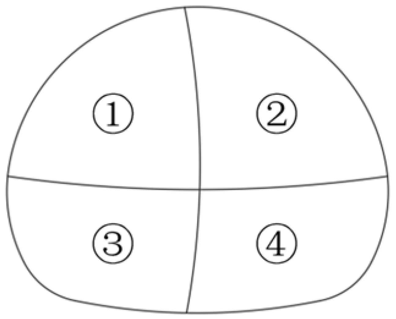
Figure 1. CRD excavation method tunnel heading No.
Buildings 15 03745 g001
Figure 2. Section of Type B Tunnel.
Buildings 15 03745 g002
Figure 3. Different grouting reinforcement layer thickness models.
Buildings 15 03745 g003
Figure 4. Tunnel grid division.
Buildings 15 03745 g004
Figure 5. Self-locking and gravity.
Buildings 15 03745 g005
Figure 6. Final settlement comparison of transverse points at Y = 5 m vs. grouting thickness.
Buildings 15 03745 g006
Figure 7. Variation curve of surface settlement value with the construction step of the measuring point right above the arch roof.
Buildings 15 03745 g007
Figure 8. Comparison between numerical simulation and site measured surface settlement.
Buildings 15 03745 g008
Figure 9. Nephogram of initial support stress.
Buildings 15 03745 g009aBuildings 15 03745 g009b
Figure 10. Comparison of Maximum Lining Stress under Different Grouting Layer Thickness.
Buildings 15 03745 g010
Figure 11. Distribution of plastic zone of surrounding rock.
Buildings 15 03745 g011
Table 1. Physical and mechanical parameters of materials.
Material NameElastic Modulus
/(MPa)
Unit Weight
/(kN/m3)
Poisson’s RatioCohesion
/(kN/m2)
Internal Friction Angle
/(°)
Moderately Weathered Argillaceous Siltstone958.022.50.3412430.21
Slightly Weathered Siltstone2146.026.70.2546242.33
Grouting Reinforcement Layer1245.424.00.2--
Initial Support2.55 × 104220.2--
Temporary Support20.0 × 104790.3--
Rock Bolt8.0 × 10482.00.3--
Grouting Small Pipe15.0 × 104780.2--
Table 2. Excavation simulation construction organization scheme.
Construction StepConstruction Content
I.SInitial State
S1-S4, S18-S21, S35-S38, S52-S55, S69-S72, S86-S89, S103-S105Construction of Upper-Left Pilot Tunnel
S5-S8, S22-S25, S39-S42, S56-S59, S73-S77, S90-S93, S106-S108Construction of Upper-Right Pilot Tunnel
S9-S12, S26-S29, S43-S46, S60-S63, S78-S80, S94-S97, S109-S111Construction of Lower-Left Pilot Tunnel
S13-S16, S30-S33, S47-S50, S64-S67, S81-S84, S98-S101, S112-S114Construction of Lower-Right Pilot Tunnel
S17, S34, S51, S68, S85, S102, S115Removal of Temporary Support
Disclaimer/Publisher’s Note: The statements, opinions and data contained in all publications are solely those of the individual author(s) and contributor(s) and not of MDPI and/or the editor(s). MDPI and/or the editor(s) disclaim responsibility for any injury to people or property resulting from any ideas, methods, instructions or products referred to in the content.