Article

Structural Behavior Analysis for Existing Pile Foundations Considering the Effects of Shield Tunnel Construction

1
Guangzhou Municipal Engineering Group Ltd., Guangzhou 510060, China
2
College of Civil Engineering, Tongji University, Shanghai 200092, China
3
Zhongshan Rail Transit Affairs Center, Zhongshan 528403, China
4
Department of Civil and Environmental Engineering, The Hong Kong Polytechnic University, Hong Kong SAR 999077, China
*
Author to whom correspondence should be addressed.
Buildings 2025, 15(18), 3263; https://doi.org/10.3390/buildings15183263
Submission received: 7 August 2025 / Revised: 1 September 2025 / Accepted: 6 September 2025 / Published: 10 September 2025

Abstract

The development of underground space, as a critical strategy for enhancing urban land use efficiency, requires careful consideration of the effects that new construction may have on existing foundations and structures to prevent safety hazards such as foundation damage. This paper investigates the influence of shield tunnel construction on the pile foundations of adjacent bridges. Based on the shield tunnel project intersecting the Haiqin Bridge pile foundations along a segment of the Guangzhou–Zhuhai Intercity Railway as a case study, a finite element (FE) model was developed. The validity of the numerical method was confirmed through comparison with existing model test results. Building on this foundation, this paper analyzed the impact patterns of shield tunnel construction on existing bridge pile foundations. Additionally, the model was employed to assess how variables such as the relative spatial positioning between the pile foundations and the tunnel, as well as the stiffness coefficient of the pile foundations, affect the structural response of the piles. The findings reveal that shield tunnel construction crossing adjacent bridge pile foundations induces bending deformation of the piles toward the tunnel side. The maximum horizontal displacement and internal forces occur near the tunnel axis, whereas the peak vertical displacement is observed at the pile head. The zone most affected by tunnel excavation extends approximately one tunnel diameter (1D) before and after the pile foundation location. The vertical relative position between the tunnel and pile foundation governs the relative displacement behavior between the pile and surrounding soil during excavation. Specifically, when the pile toe moves downward relative to the tunnel, the excavation’s influence on the pile foundation shifts from being dominated by negative skin friction and settlement to positive skin friction and rebound, leading to substantial changes in the force distribution and displacement patterns within the pile. As the horizontal clearance between the tunnel and pile foundation increases, the internal forces and displacements within the pile foundation progressively diminish and eventually stabilize. Furthermore, an increase in pile stiffness coefficient decreases the maximum pile displacement and increases internal forces in the pile shaft. Pile diameter has a greater influence than Young’s modulus, which exhibits a relatively minor effect.

1. Introduction

The advancement of urban underground space has garnered significant attention as a crucial strategy for mitigating the current scarcity of urban land resources. However, the implementation of open-cut methods for underground space development presents challenges, thereby limiting the effective utilization of only localized areas for the construction of underground tunnels necessary for building development. Shield tunneling has emerged as the preferred method for urban tunnel construction due to its safety, efficiency, and minimal disruption to the surrounding environment [1,2]. The construction of urban underground tunnels often requires the intersection of new tunnels with existing structures, such as bridges, that are located in close proximity [3,4]. In geologically complex environments, the process of shield tunneling can induce stress redistribution and soil displacement in the surrounding area, which may adversely affect existing structures, including the foundations of bridge piles [5,6]. The consequences of these impacts can be categorized into three primary areas: (1) disturbances to the soil during the construction phase, (2) alterations in the additional stress experienced by the piles, and (3) potential long-term risks of settlement. Excessive reliance on empirical methodologies, without a thorough evaluation of the specific conditions relevant to each project, can lead to structural failures [7], as evidenced by the cracking observed in adjacent buildings during the construction of Shenzhen Metro Line 5 in China [8]. Therefore, it is essential to conduct comprehensive research on the interaction mechanisms between shield tunnels and pile foundations, as well as to assess their impacts, in order to protect urban infrastructure and promote sustainable urban development [9].

1.1. Theoretical and Experimental Research on Tunnel Construction on Nearby Pile Foundations

The interaction mechanism of adjacent piles involves complex tunnel–soil–pile interactions. Primary research methodologies can be broadly categorized into (1) theoretical analysis, (2) experimental research, and (3) numerical simulation.
To investigate the effects of tunnel construction on adjacent pile foundations, numerous researchers have conducted both theoretical and experimental studies. Liang et al. [10] utilized the elastic foundation beam model in conjunction with the single-parameter Winkler foundation model to derive analytical solutions for the bearing capacity of existing pile foundations subjected to horizontal loads and decompose their nonlinear deformation responses. Zhang et al. [11] incorporated the lateral soil influence surrounding piles and proposed an analytical model for pile–soil interaction under lateral soil effects, based on the two-parameter Pasternak foundation model. To improve the accuracy of predicting deformation responses of adjacent pile foundations induced by tunnel excavation, Zhang et al. [12] employed the three-parameter Kerr foundation model to simulate pile–soil interaction and analytically derived the solution for the difference in horizontal deformation of adjacent pile foundations caused by shield tunneling. Their findings, compared with those from the Winkler and Pasternak models, indicated that the Kerr foundation model more accurately represents the actual deformation behavior of pile foundations. Building upon the Kerr foundation model, Jia et al. [13] accounted for lateral soil displacement effects on adjacent piles and performed detailed calculations of lateral displacement and bending moments in piles resulting from shield tunnel excavation. Wu et al. [14] further derived the analytical solution of greenfield ground displacement induced by tunneling considering multiple excavation factors such as face pressure, grouting pressure, ground losses, shell friction, etc. Chao et al. [15] established a computational method to assess the deformation of existing bridge pile foundations affected by shield tunnel construction and identified the main factors influencing pile shaft deformation. Zhou et al. [16], using thin-walled theory, investigated the mechanisms by which tunnel construction influences adjacent pile foundations and assessed their elastic responses. Ng et al. [17] conducted three-dimensional (3D) centrifuge model tests to analyze the impact of double-tunnel construction on existing single piles in dry sand, revealing that pile settlement due to double-tunnel excavation strongly depends on the relative depth of each tunnel with respect to the pile. Soomro et al. [18,19] explored the stress transfer mechanisms and deformation characteristics of existing pile foundations affected by the excavation of double-track stacked tunnels and parallel tunnels within sandy soil layers through centrifugal model testing. He et al. [20] performed indoor physical model experiments using a developed micro-tunnel boring machine to simulate the effects of shield excavation in clayey soils on existing pile foundations, subsequently comparing the experimental results with numerical simulation data. Su et al. [21] conducted a model test to investigate the influence of shield tunneling on pile foundations under varying groundwater conditions. Their results indicated that both the axial force and lateral displacement of piles in water-rich strata increased significantly compared to those in dry strata. Guo et al. [22] performed a model test on pile foundations adjacent to a shield tunnel project within the Beijing subway system, elucidating the evolution of characteristic pile deformations during tunnel excavation. Theoretical analyses require considerable simplification of models and assumptions, making them suitable primarily for straightforward geological settings and regular geometrical configurations but insufficient for accurately representing the complexities encountered in practical engineering applications. Experimental modeling generally investigates a limited range of operating conditions, with outcomes potentially influenced by environmental variables and scale-related effects.

1.2. Numerical Simulation Research on Tunnel Construction on Nearby Pile Foundations

Numerical simulation approaches for soil–structure interaction problems primarily fall into two categories: simplified numerical analysis and full 3D simulation. Simplified methods, such as the Winkler foundation model (modeling soil as a series of independent springs) or two-dimensional plane strain analysis, have been extensively employed by researchers to gain preliminary insights into the system’s global response at a low computational cost. For instance, Kitiyodom et al. [23,24] proposed a simplified numerical method for analyzing piled raft foundations under axial and lateral loading in heterogeneous soils, and evaluated the effects of tunnel excavation on adjacent piles using a Winkler-based elastic foundation beam model, with its accuracy being validated. Asgarkhani et al. [25] employed a simplified numerical analysis method that could take into account soil–foundation–structure interaction to rapidly assess the seismic response of the structure.
However, these simplifications inevitably introduce limitations, primarily due to the neglect of complex 3D continuum effects, the intricate kinematics of soil movement around the structure, etc. To overcome these limitations, full 3D numerical simulation provides a comprehensive approach to modeling soil–structure interactions, enabling detailed parametric analyses of influencing factors. Consequently, it has become widely used in engineering research related to tunneling effects on piles. Lee et al. [26] performed 3D finite element (FE) analyses on loaded single piles subjected to nearby tunneling, revealing that soil plastic yielding occurs when excavation approaches within one tunnel diameter (1D) of the pile. Their findings also indicated that surface settlement at the pile location was substantially less than the settlement at the pile head, suggesting that the Gaussian settlement distribution is not applicable to existing pile heads. Yang et al. [27] categorized the soil surrounding the tunnel into three distinct zones—above-tunnel, 45°-direction, and lateral—and quantified variations in pile side friction, end-bearing resistance, and axial load distribution during shield advancement for piles situated in each zone. Jongradist et al. [28] conducted an extensive investigation into the effects of tunnel construction on laterally loaded piles under diverse conditions, defining excavation influence zones based on ratios of pile settlement to surface settlement and maximum bending moments. Liu et al. [29] utilized nonlinear finite element methods to analyze displacement fields in the soft soils of Shanghai, demonstrating that piles closer to tunnels experience greater construction-induced disturbances. Boonyarak et al. [30] examined the influence of ground loss and burial depth, concluding that pier tilting—predominantly oriented toward the tunnel—is primarily attributable to long-term subsurface settlement, accounting for approximately 80% of total settlement. Soomro et al. [31] applied 3D coupled consolidation FE modeling, identifying the proximity of the tunnel face, rather than the completion of excavation, as the critical phase for pile settlement, tilting, and bending moments. Zidan et al. [32] compared pile behavior under free-field conditions and during tunnel excavation in soft soils, observing a 20% increase in bending deformation during excavation. Additionally, when tunneling beneath piles, abutment settlements reached nearly 40% of the maximum total settlement. Li et al. [33] investigated multi-stage tunneling in layered soils, exploring interaction mechanisms among single, double, and group piles, and characterizing friction distribution on existing piles during excavation-induced unloading. Dai et al. [34] studied the effects of twin-tunnel side-crossing on bored piles, revealing that shield construction induces repeated disturbances that affect bearing characteristics. Huang et al. [35,36] developed refined 3D tunnel–soil–pile models based on fluid-structure interaction theories, analyzing pier settlements, pile displacements, and surface deformations under various conditions within stratified foundations. Ayasrah et al. [37] conducted mechanical analyses of piles during twin-tunnel undercrossing, emphasizing the significant influence of burial depth. Lv et al. [38] examined tunneling through bridge piles in soft-hard soil strata, quantifying surface settlement and pile responses, and proposing allowable disturbance thresholds. Finally, Zhang et al. [39] addressed the issue of transverse passage of shield tunnels through pile foundations, evaluating the effects of vertical load, tunnel–pile spacing, and cover depth on adjacent pile displacement and bending moments. Nabil et al. [40] examined the response of pile foundations subjected to ground motion induced by tunneling in a two-layered soil system, considering two pile-head conditions: free-head and capped-head. Ning et al. [41] analyzed pile foundation deformation resulting from shield tunneling in silty fine sand strata in Nantong and proposed a practical method for estimating pile settlement.
In summary, the current literature indicates that existing theoretical frameworks and model experiments insufficiently capture critical parameters in shield construction, such as tunneling speed, grout volume, grouting pressure, frictional resistance of the shield shell, and soil chamber pressure. As a result, significant discrepancies exist between predicted results and empirical measurements. Furthermore, the limited availability of comprehensive field measurement data hinders the development of extensive datasets essential for practical engineering applications, thereby restricting wider adoption in the field. Numerical simulation provides a powerful tool for overcoming the limitations of experimental, theoretical, and field-measured data, enabling a more accurate analysis of the mechanical behavior of pile foundations throughout the entire tunneling process. However, current research of numerical simulation methods remains insufficient for fully capturing the continuous excavation sequence and advancement rate of shield tunneling machines, the magnitude and impact of construction-induced loads, the variability of grouting material properties, and the stress release phenomena in the surrounding soil. Thus, this study incorporates experimental data from the literature to validate the finite element modeling framework. The investigation focuses on key parameters, including the relative positioning of tunnels and pile foundations, pile foundation stiffness, and grouting pressures, with the goal of elucidating the structural response of pile foundations during tunneling construction.

1.3. Objectives and Scope of Work

This paper aims to investigate the effects of tunnel construction on adjacent pile foundations by developing a FE model of an underground shield tunnel intersecting the Haiqin Bridge pile foundation within a specific segment of the Guangzhou–Zhuhai Intercity Railway. The validity of the FE modeling approach is confirmed through comparison with existing experimental data, followed by a comprehensive parametric analysis. This paper investigates the following research topics:
  • Developing a comprehensive FE model that incorporates geological conditions and construction processes, and validating its accuracy using published experimental data;
  • Analyzing the structural performance of pile foundations in different construction stages based on FE results;
  • Conducting a parametric FE method analysis to evaluate the structural behavior of pile foundations in tunnel construction, taking into account various horizontal distances between the tunnel and pile foundations, vertical distances between the tunnel and pile foundations, the stiffness of the pile foundations, and grouting pressures.

2. Finite Modeling of Shield Tunneling Beneath Bridge Foundations

2.1. Project Overview

The Guangzhou–Zhuhai Intercity Railway runs along the western bank of the Pearl River Estuary, creating a dedicated passenger transportation corridor that connects the cities of Guangzhou and Zhuhai in Guangdong Province, China. In the Zhuhai segment, a double-track tunnel is constructed collinearly beneath a bridge, intersecting directly with the bridge pile alignment (as shown in Figure 1). The minimum horizontal clearance between the right-line tunnel and the 0# abutment pile is 5.22 m. This tunnel was built using shield tunneling methods, featuring an excavation diameter of 8.85 m and a shield length of 16 m. The tunnel lining segments have an outer diameter of 8.5 m, a thickness of 0.4 m, and a width of 1.6 m per ring. The tunnel axis is located 24.35 m below the ground surface, with a center-to-center spacing between the left and right tunnels of 21.46 m. The bridge, situated on a curve with a radius of 1160 m and spanning 195 m (comprising 37.5 + 3 × 40 + 37.5 m), crosses an artificial inland channel. Its superstructure consists of restressed concrete box girders supported by six bored piles per cap. These end-bearing piles have a diameter of 1.8 m and a length of 55 m, with transverse spacing (perpendicular to the bridge) of 21.25 m and longitudinal spacing of 4 m.

2.2. Material Parameters

The stratigraphic sequence at the bridge site, arranged from the surface downward, consists of artificial fill (after treatment), silt, clay, coarse sand, and sandy clay, followed by granite exhibiting varying degrees of weathering classified as fully, strongly, and moderately weathered. The mechanical behavior of the stratum soil was simulated using the Mohr–Coulomb elastoplastic constitutive model, and its basic physical property indices are presented in Table 1. It should be noted that the shield tunnel primarily advances through the clay layer. To enhance the foundation performance in the vicinity of the bridge, a series of concrete piles measuring 8.5 m in length were installed in the artificial fill layer. As reference [42], the compression modulus of the treated artificial fill layer can be calculated according to Equation (1):
E sp = m E p + 1 m E s
where Esp is the compression modulus of the treated artificial fill layer (i.e., the composite foundation); Ep is the compression modulus of the concrete pile, which can be taken as 100 to 120 times the compressive strength of the pile; Es is the compression modulus of the soil between the piles; and m is the replacement rate of the composite foundation, which can be obtained from the design drawings.
The calculated compression modulus of the artificial fill (after treatment) and the recommended basic physical property indices given in the geotechnical engineering investigation report are presented in Table 1.
Subsequent to shield excavation, tunnel lining segments are installed, and grout is injected into the annular space between the segments and the surrounding soil. These segments, composed of precast C50 concrete, are arranged to form rings consisting of seven segments connected by longitudinal and circumferential bolts. To streamline the simulation and circumvent the need to model the ring assembly process explicitly, the stiffness of individual rings was reduced by applying a reduction factor of 0.15 [43]. The shield machine shell was represented using Q235 steel, whereas the pile was modeled as cast-in-place underwater C35 concrete. The grout curing process was simulated employing the stiffness migration method, which distinguishes between the initial and final setting stages [44,45]. All materials were characterized by a linear elastic constitutive model, with their respective material properties summarized in Table 2.

2.3. Modeling

Based on the on-site construction sequence, the foundation within the bridge site area was prepared prior to the commencement of shield tunnel construction, with only the bridge piles completed at that stage. Consequently, in the numerical simulations conducted within this study, the bridge pile foundations are modeled to be analyzed under the self-weight and soil–pile interaction forces, excluding any superstructure or traffic-induced loads. As illustrated in Figure 1, the spatial relationship between bridge caps numbered 2# through 5# and the tunnel is similar to that observed between the 0# cap and the tunnel. Notably, the pile closest to the tunnel is located at the 0# cap. Consequently, the model established by MIDAS GTS NX 2023R1 primarily focuses on the piles at the 0# and 1# caps, the tunnel structure, and the surrounding soil (Figure 2). The coordinate system defines the x-axis along the tunnel centerline, the y-axis horizontally perpendicular, and the z-axis vertically upward. Considering that soil disturbance is typically confined within 3–5 times tunnel diameters from the tunnel center [46], the model size was set to 265 m × 140 m × 90 m, minimizing boundary effects [40]. Soil and tunnel lining were meshed with tetrahedral elements, the shield shell with plate elements, piles with beam elements, and grout with plate elements. Except for the soil which adopts the Mohr–Coulomb constitutive model, all other materials adopt the linear elastic constitutive model. Tied contact was assumed between soil–pile and soil–tunnel interfaces [47]. In this numerical model, the upper boundary of the artificial fill (after treatment) layer is designed to reflect real-world conditions and is defined as a fully free surface. Since the entire model is isolated from the surrounding soil mass, normal deformation constraints perpendicular to the plane are applied along its perimeter, while vertical deformation constraints are not imposed. Furthermore, because the model’s base rests on a bedrock layer, this boundary is considered rigid and is therefore subjected to rigid body constraints.

2.4. Construction Phase Simulation

The simulation replicated the sequence of field construction by first modeling the left tunnel, followed by the right tunnel. It should be noted that due to the significant time interval between the completion of the left tunnel and the commencement of the right tunnel in actual construction practice, the displacement of the bridge pile foundations had stabilized before the construction of the right tunnel began. Therefore, upon completion of the left tunnel, a displacement reset is necessary, with particular attention given to assessing the impact of the right tunnel construction on the internal forces and deformation of the bridge pile foundations. As illustrated in Figure 3, the shield tunneling process was represented through a systematic approach involving element removal, activation, and property modification, organized into three distinct phases.

2.4.1. Shield Excavation

To optimize computational efficiency and streamline the excavation process, the excavation of five rings (equivalent to 8 m) is consolidated into a single excavation step. Axial pressure, directed along the positive x-axis, is applied to the subsequent excavation face to simulate the chamber earth pressure. Simultaneously, the shield shell plate element corresponding to this excavation is activated, and the frictional resistance exerted by the shield machine on the surrounding soil surface is incorporated. Upon completion of each excavation step, the chamber earth pressure associated with that step is promptly removed, and the chamber earth pressure is then applied to the next excavation face. This approach effectively simulates the sequential progression of the excavation process.

2.4.2. Segment Assembly and Synchronous Grouting

While the shield machine is advancing forward, it begins assembling the segments and synchronously grouting after the first excavation step is completed. The assembly of segments is simulated by adding segment elements, modifying the material properties from the shield shell element of previous excavation step to the initial setting grouting to simulate initial grouting, and applying circumferential surface force on the outer surface of the segment to simulate grouting pressure. After the assembly of the segment is completed, the next excavation step requires applying a negative jack force along the x-axis to the end ring of the segment assembled in the previous excavation step. Similarly, when assembling the next ring of the segment, the jack force applied in the previous excavation step needs to be removed, and segment assembly and the synchronous grouting process need to be simulated forward in sequence.

2.4.3. Hardening of Grouting Body

The hardening process of the grouting body is considered based on the duration of one excavation step; that is, in the next excavation step after the initial grouting is completed, the initial setting property of the grouting body of the previous excavation step is changed to the final setting property, and the grouting pressure is removed, to simulate the hardening process of the grouting body in sequence.
According to on-site construction data, the chamber earth pressure in the shield tunneling is 320 kPa, and the grouting pressure is 300 kPa. The frictional resistance of the shield machine on the surrounding soil during excavation is calculated to be 105.2 kPa [48], while the frictional resistance of the shield shell can generally reach 45% of the total thrust of the shield jack [49], and the total thrust of the jack can be calculated to be 233.78 kPa.

2.5. Calculation Assumption

To enhance computational efficiency while preserving the accuracy of finite element analyses, the following assumptions are adopted for the finite element modeling and computational procedures, in accordance with the recommendations outlined in the relevant literature [50]:
  • The rock and soil masses are modeled using the Mohr–Coulomb elastic–plastic constitutive model, with stratigraphic layers appropriately simplified based on the site geological investigation report.
  • Groundwater effects are neglected due to the tunnel’s location beneath a river, the abundance of water resources in the surrounding area, and the predominance of saturated soil conditions.
  • All materials are assumed to behave as homogeneous, isotropic, and continuous media. The relative displacement between the soil and tunnel or pile foundations is disregarded, implying a coupled soil–structure displacement response.
  • During the construction of the shield tunnel segment beneath Haiqin Bridge, the existing bridge pile foundations are considered only under normal service conditions; seismic and civil defense scenarios are excluded from the analysis.

3. Numerical Verification

Numerical simulation methods often lack persuasiveness due to insufficient field data for verification and calibration. Therefore, referencing the centrifugal model experiment in [17], an identical numerical model was developed using MIDAS GTS NX 2023R1. Comparing results from both methods verifies the reliability of this study’s numerical approach.
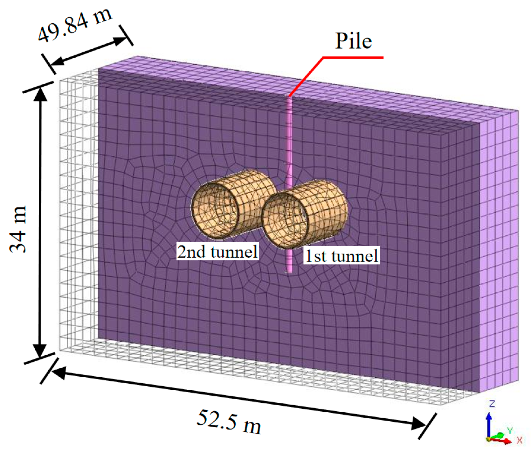
As shown in Figure 4, a 3D numerical model measuring 52.5 m × 49.84 m × 34.0 m was established. The tunnel lining segments were modeled with an outer diameter of 6.08 m and an inner diameter of 5.68 m, with the tunnel centerline located 12.0 m below the ground surface. The pile, positioned midway between the twin tunnels, featured a diameter of 0.8 m and an embedded length of 19.6 m in the soil. The distance between the pile axis and each tunnel centerline was 4.56 m. Boundary conditions included fixed supports at the model base and roller supports on the lateral faces. The soil mass was simulated using solid elements governed by the Mohr–Coulomb elastoplastic constitutive model. Tunnel lining segments were represented by plate elements, while the pile was modeled using beam elements. Material properties assigned to these components, based on actual project data, are detailed in Table 3. The excavation sequence initiated with the right tunnel (first tunnel), followed by the left tunnel (second tunnel).
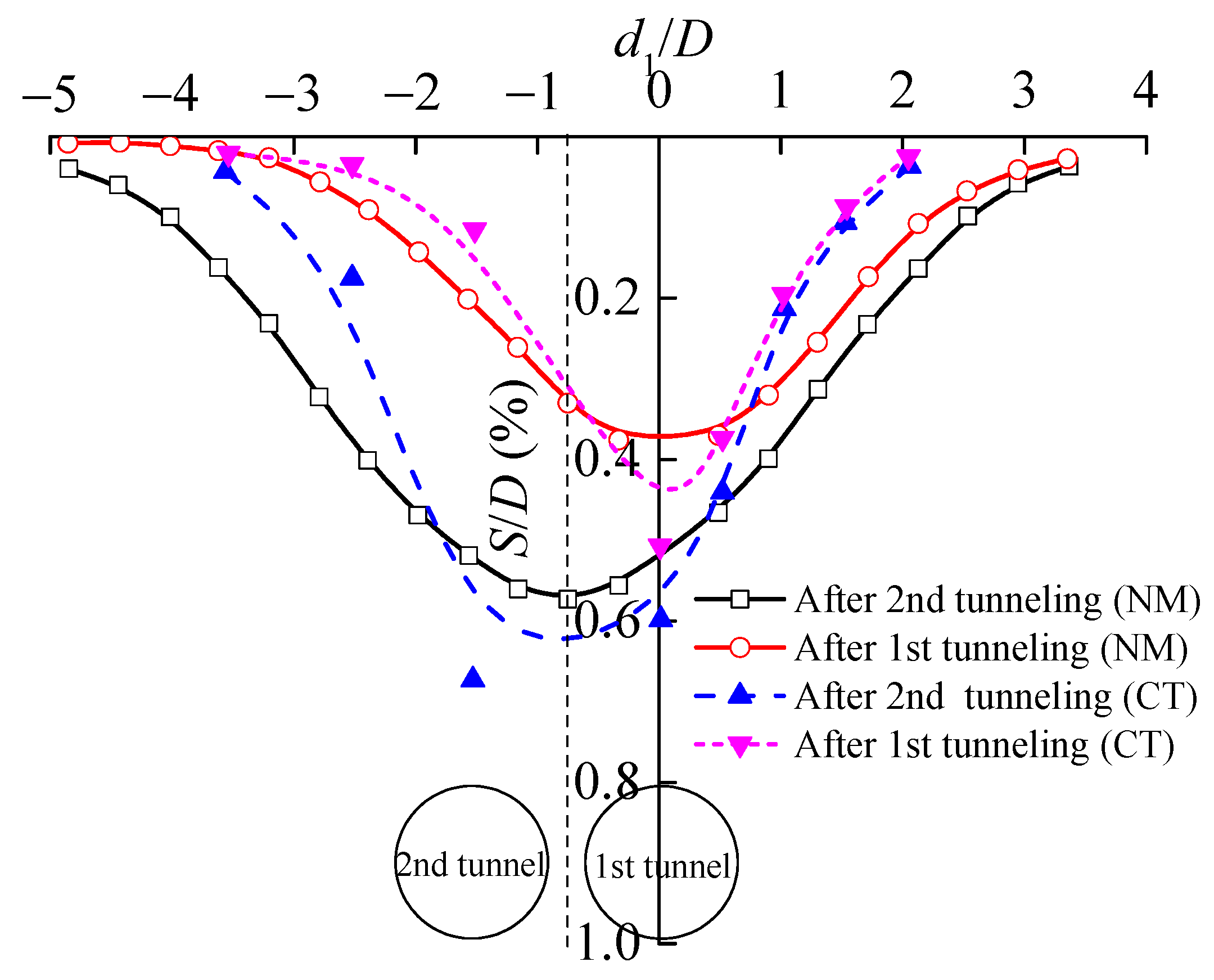
Figure 5 shows the comparison of ground surface settlement after tunnel excavation, where NM represents the numerical calculation value and CT represents the centrifugal test value; both the surface settlement (S) and the transverse distance from the center line of the first tunnel (d1) were normalized by the tunnel diameter (D). As shown in the figure, upon completion of the first tunnel excavation, the maximum surface settlement from numerical simulation is 22.8 mm, compared to 26.1 mm in centrifugal tests. After excavating the second tunnel, the numerical simulation yields a maximum settlement of 34.8 mm, versus 37.1 mm in centrifugal tests. Centrifugal test results consistently exceed numerical values, likely because the tunnel segments were simulated using water bags combined with a metal skeleton in the centrifuge—a configuration with lower stiffness that may cause excessive soil settlement. Nevertheless, the surface settlement trough curves from both methods show good agreement, with maximum settlement occurring directly above the centerlines of both tunnels.
Figure 6 shows a comparison of the internal forces of the pile after tunnel excavation, where zp represents the burial depth of the pile. It can be seen that the distribution curves for axial force and bending moment on adjacent piles induced by shield tunnel construction, derived from numerical calculations, closely match those obtained from centrifugal tests. Negative bending moments occur at the upper and lower sections of the pile, while positive bending moments occur in the middle. The maximum bending moment from numerical calculations is 146.0 kN·m, closely matching the 123.6 kN·m measured in centrifugal tests. Due to the load acting on the pile head, the axial force gradually decreases with increasing depth until, beyond the tunnel depth, it decreases rapidly with further depth increase. Following the excavation of the second tunnel, the pile’s axial force shows minimal change, and numerical results remain consistent with centrifugal test results. The maximum axial force calculated numerically is 1817.2 kN, comparable to the centrifugal test result of 2027.5 kN.
Based on the above analysis, numerical simulations were conducted to replicate existing centrifugal tests. The calculated distribution curves of surface settlement, pile axial force, and bending moment along the pile closely match the experimental results, demonstrating the reliability of the numerical analysis method.

4. Numerical Calculation Results on the Bridge Pile

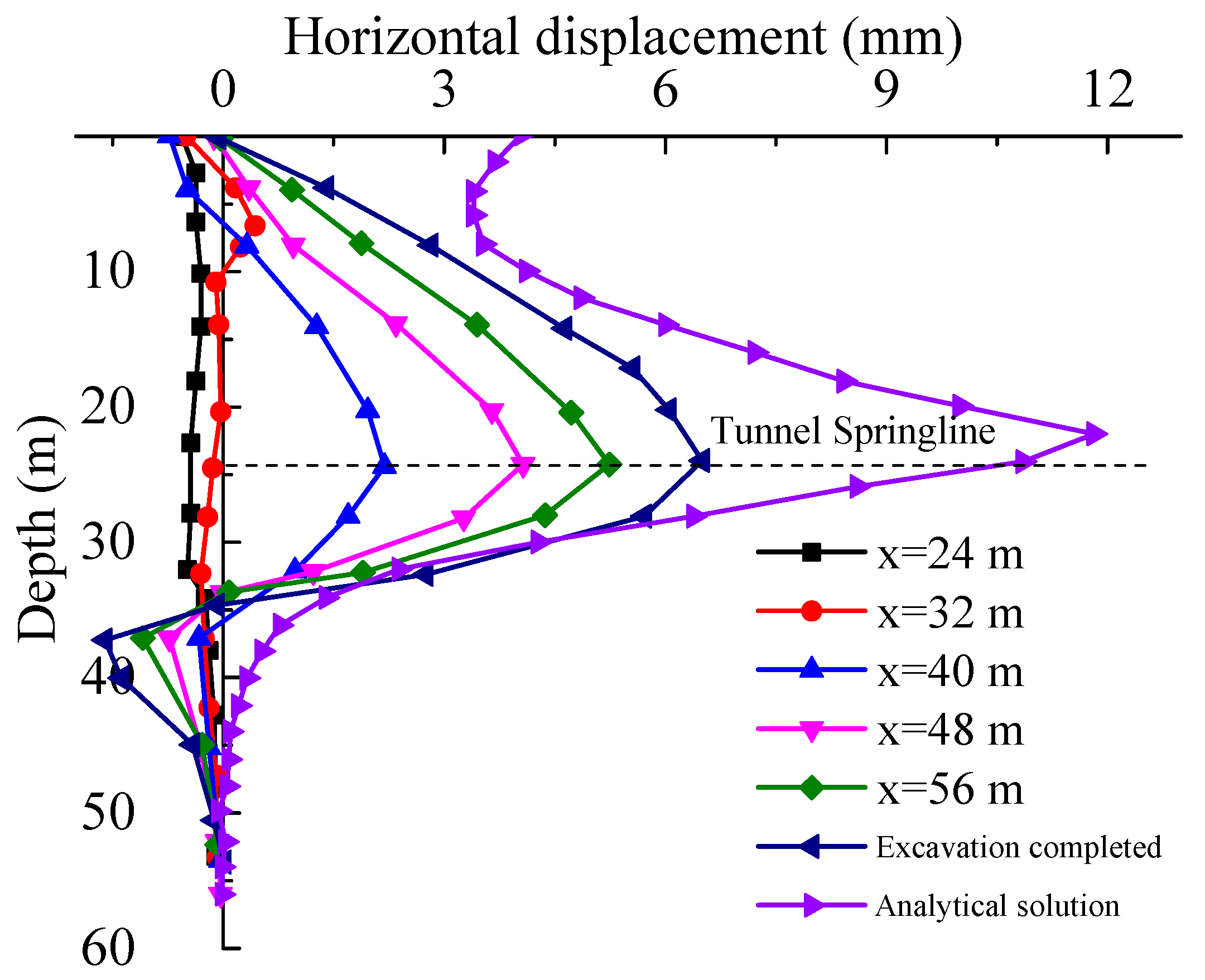
The distance between the shield excavation face and the pile varies with shield advancement. To study the impact of shield tunneling on adjacent bridge piles, the displacement and internal forces of the #1 pile at 0# abutment were analyzed. Data were extracted for five excavation steps: from two steps ahead to two steps behind the benchmark face (where the excavation face aligns with the pile at x = 40 m), corresponding to x = 24 m~x = 56 m in Figure 2. The plane relationship between the excavation face and pile is shown in Figure 7. A comparison of the numerical predictions and the classical analytical solution proposed by Poulos and Chen [51] was conducted to assess the model’s fidelity.

4.1. Horizontal Displacement

The pile horizontal displacement distribution is shown in Figure 8. When x < 40 m (pre-arrival), the pile exhibits minimal horizontal displacement, primarily deforming away from the tunnel. At x = 40 m (face arrival), significant bending deformation occurs toward the tunnel side. The horizontal displacement increases, peaking at 2.2 mm near the tunnel axis. This resulted from soil unloading adjacent to the pile, which reduced the normal and tangential frictional resistance of the surrounding soil, inducing additional horizontal deformation. With shield tunneling, the deformation of pile continues to increase, reaching a maximum horizontal displacement of 5.4 mm (x = 56 m). Due to the high constraint ability of the pile-end soil, it behaved as an embedded member, exhibiting near-zero horizontal displacement.
Following the completion of tunnel excavation, the maximum horizontal displacement of the pile foundation obtained through numerical simulation was approximately 6.92 mm, whereas the analytical solution yielded a value of 12.16 mm, indicating a notable discrepancy between the two. This divergence can be primarily attributed to the simplified treatment of pile–soil interaction in the analytical solution. Moreover, the soil deformation induced by the first stage of shield tunneling exerts a considerable influence on the pile response during the second stage of surrounding soil movement. The computation of shield-induced soil deformation is directly related to the ground loss ratio ε, which therefore also plays a significant role in the results. Nevertheless, the variation trends in the horizontal displacement curves of the pile foundation obtained from the two-stage analytical method and the numerical simulation are generally consistent.
The horizontal displacement variation in the pile at the tunnel axis with shield tunneling is shown in Figure 9. At x = 32 m (about 1D ahead of the pile), the pile deforms toward the tunnel. The horizontal displacement increased steadily, stabilizing near 6.2 mm when the shield reached x = 64 m, where only grouting pressure effects persist. A rapid increase (approximately 60% of total horizontal displacement change) occurred specifically during tunneling through the pile (x = 32 m~x = 48 m). This confirms that the primary influence zone spans about 1D around the pile.

4.2. Vertical Displacement

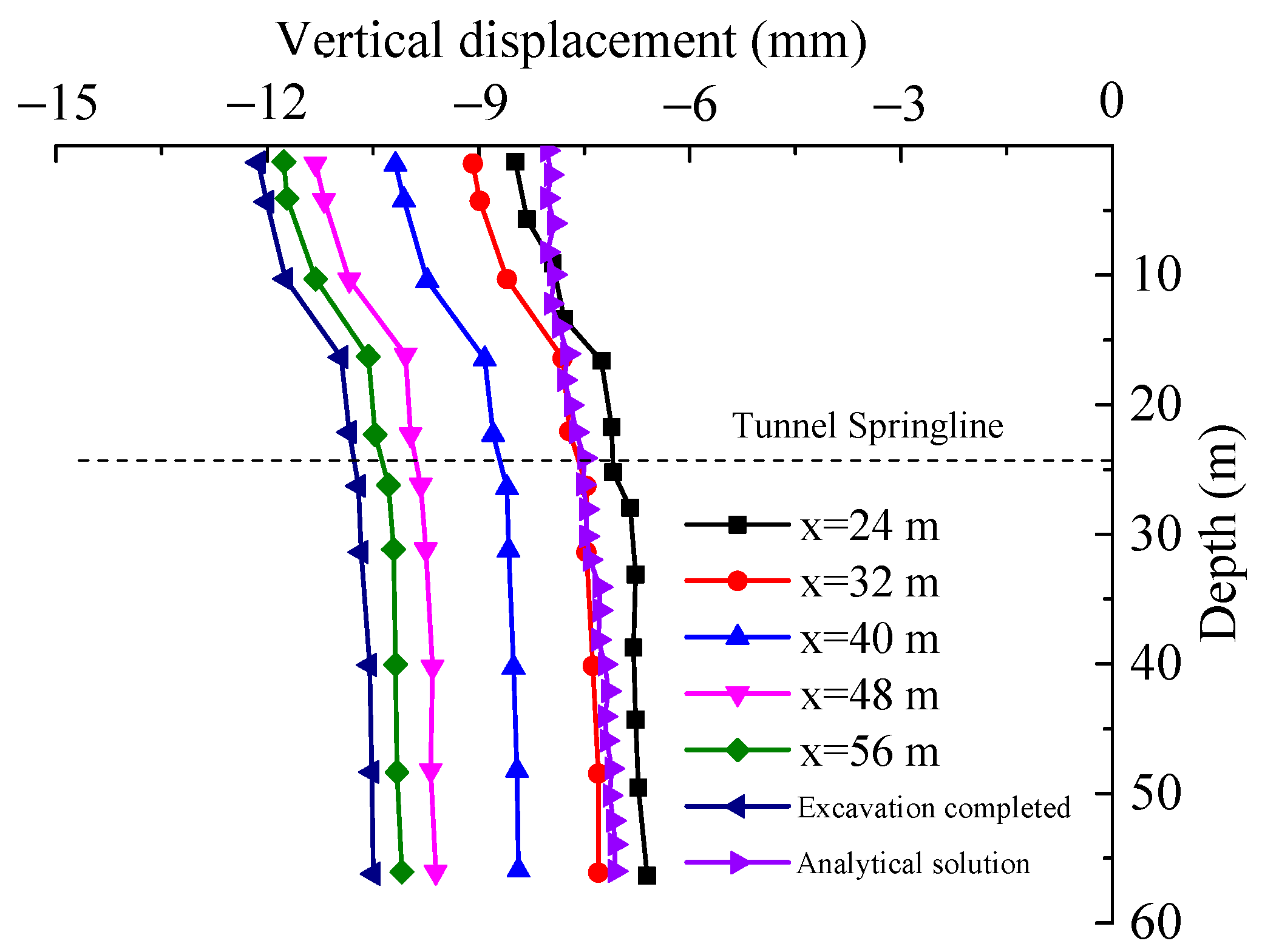
Figure 10 presents the vertical displacement distribution along the pile. As shown, the pile exhibits an overall settlement trend. The vertical displacement remained relatively uniform along the pile length, with slightly greater values observed in the upper section compared to the lower section. This behavior primarily arises from the significantly higher stiffness of the pile relative to the surrounding soil. The additional axial force induced by shield tunneling caused minor compressive deformation of the pile, leading to its settlement. Displacement at the pile toe, constrained by the bearing capacity of the pile-end soil and shaft friction, was lower than that at the pile head. As tunneling progressed, pile settlement increased, with the vertical displacement at the pile head rising from 8.5 mm (x = 24 m) to 11.4 mm (x = 56 m), representing an increase of approximately 40%.
As for the maximum vertical displacement after the tunnel excavation is completed, the numerical simulation resulted in a value of approximately 11.4 mm, which is significantly larger than the 8.54 mm derived from the analytical solution. This discrepancy arises because the numerical model comprehensively accounts for various construction loads, leading to greater deformation of the soil surrounding the pile and consequently inducing larger settlement. In addition, the homogenization simplification of the soil in the analytical model deviates substantially from real-world conditions. Despite these differences, the variation trends in the vertical pile displacements obtained from both methods are relatively consistent, though the analytical solution exhibits relatively lower accuracy in quantitative terms.
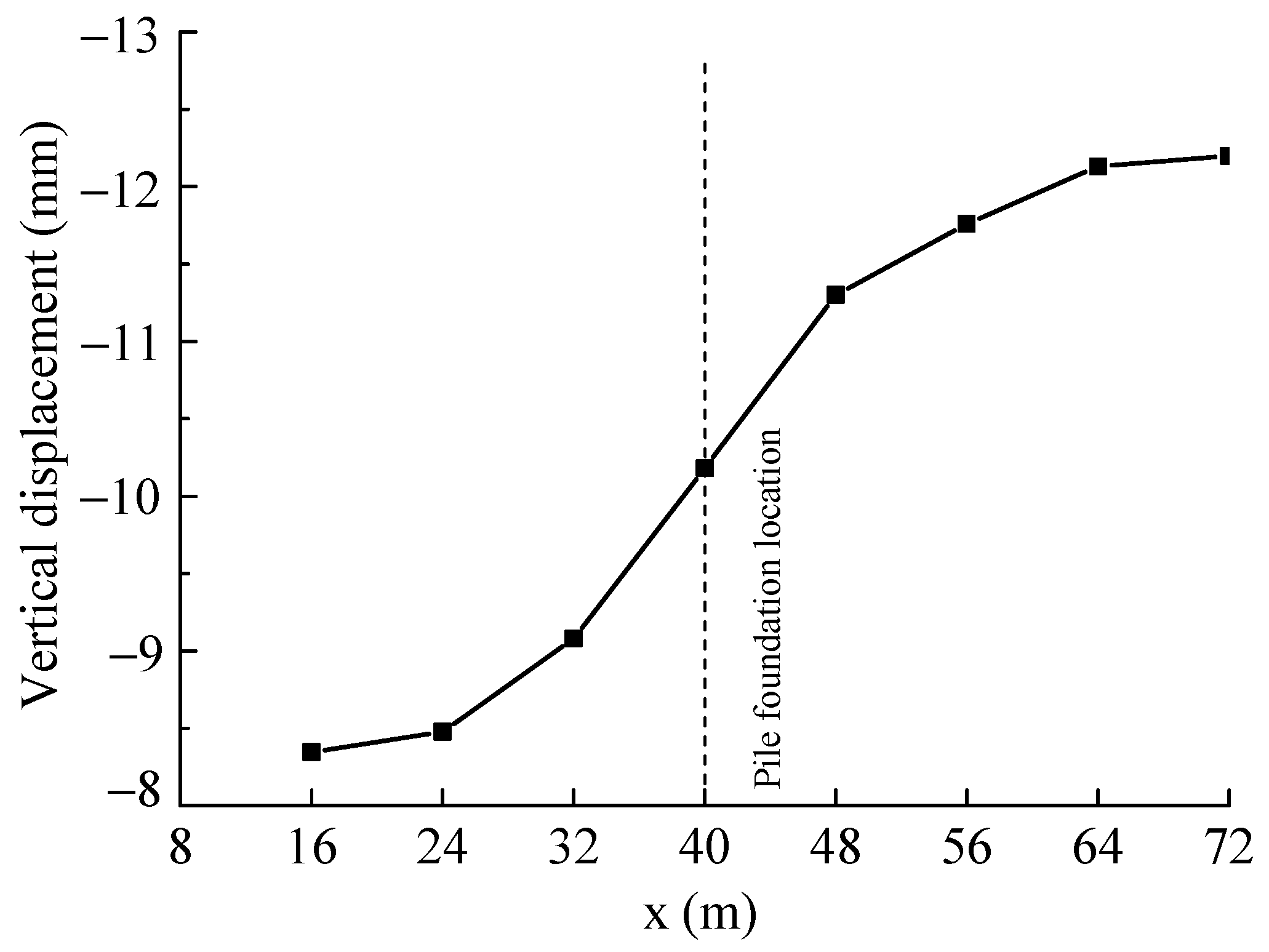
Figure 11 illustrates the variation in pile head vertical displacement during shield advancement. Similar to the horizontal displacement behavior at the tunnel axis, the pile head vertical displacement increased from 9 mm to 11.3 mm as the shield passed the pile location. This increase accounted for approximately 60% of the total change observed during the entire analysis period, further indicating that the primary influence zone of shield tunneling on the pile extends to about 1D from the pile. The pile head displacement stabilized only after the shield advanced to x = 64 m.

4.3. Axial Force

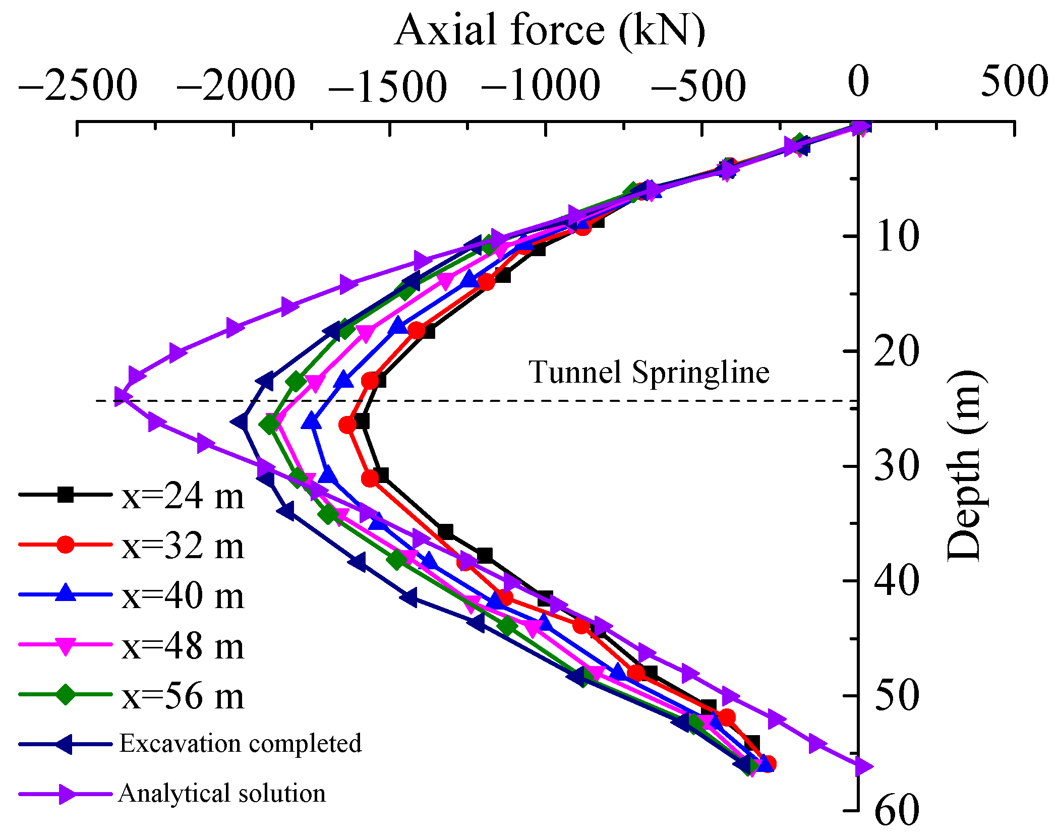
Figure 12 presents the axial force distribution along the pile. As shown, the axial force increased progressively with shield advancement and exhibited a “C-shaped” distribution along the pile length. The maximum axial force occurred near the tunnel axis and decreased gradually towards both pile ends. This pattern arises because shield tunneling induces settlement in the soil above the tunnel axis. This downward soil movement relative to the pile generates negative skin friction, increasing the axial force. Conversely, soil rebound below the tunnel axis due to unloading causes the pile-end soil to move upward relative to the pile, reducing the axial force.
The maximum axial force obtained from numerical simulation following tunnel excavation was 2080.6 kN, which is 12% lower than that calculated using the analytical method (2367.2 kN). The variation trends in the axial force curves derived from both methods are generally consistent, with the maximum axial force in both cases occurring near the pile section at the tunnel axis. The differences between the two methods can be attributed to the reasons mentioned earlier: the analytical solution relies on a number of simplifying assumptions, and the selection of parameters such as the ground loss ratio ε also directly affects the computational results.
The axial force variation in pile at tunnel axis with shield tunneling is shown in Figure 13. The trend closely resembles that of the pile head vertical displacement. The axial force increased from 1550 kN to 1870 kN, with the 202 kN increase occurring during shield passage past the pile accounting for the majority of this change. The influence of other construction stages on axial force was relatively minor.

4.4. Bending Moment

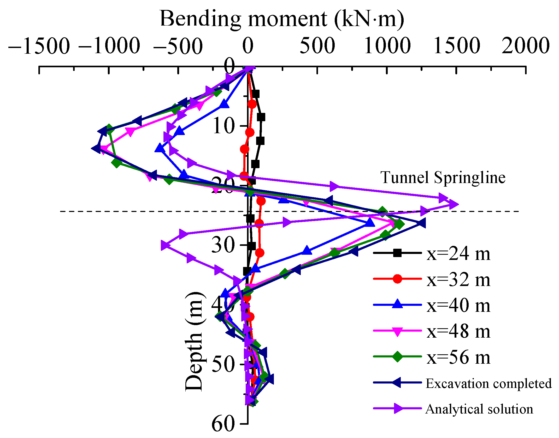
Figure 14 shows the bending moment distribution along the pile. In the figure, a positive bending moment indicates tension on the tunnel side (bending towards the tunnel), while a negative bending moment indicates tension on the far side (bending away from the tunnel). Corresponding to the horizontal deformation behavior, the lateral constraint on the pile was significantly reduced by tunnel excavation unloading. This allowed offset loading to induce bending deformation. Consequently, additional bending moments developed, displaying an inverted “bow” distribution along the pile.
The variation trend of the bending moment curve obtained from numerical simulation after tunnel excavation is in good agreement with that from the two-stage analytical solution. The maximum positive bending moment in both cases occurs near the pile section at the tunnel axis. However, the maximum negative bending moment in the upper part of the pile obtained numerically is significantly larger than that from the analytical solution. This discrepancy arises because the analytical solution simplifies the strata as uniform layers, whereas in reality, the subsurface is non-uniform. Additionally, the presence of an 8.5 m thick artificial fill layer reinforced with concrete piles beneath the surface—a factor not accounted for in the analytical model—further contributes to the difference. Thus, the numerical simulation offers a more comprehensive consideration of relevant factors, yielding relatively more accurate results.
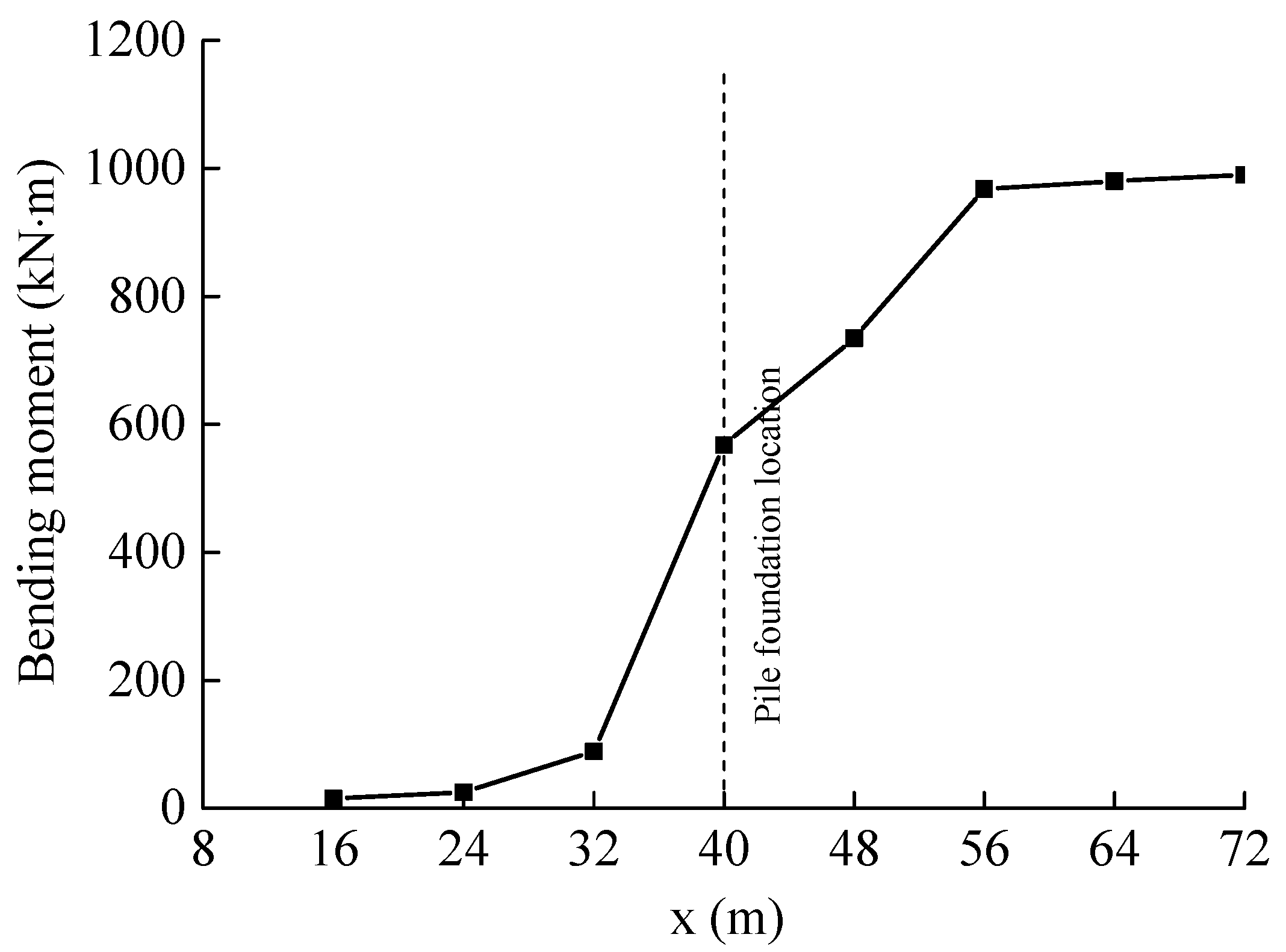
The bending moment variation in the pile at the tunnel axis with shield progress is shown in Figure 15. The bending moment increased with tunneling, exhibiting a pronounced change (accounting for 65% of the total variation) specifically during shield passage past the pile. This highlights that particular attention should be paid in engineering practice to changes in pile displacement and internal forces when tunneling advances within approximately 1D of the pile.

5. Parametric Analysis

This section focuses on three critical factors: the horizontal tunnel–pile relative position, the vertical tunnel–pile relative position, and the pile stiffness coefficient. Employing a single-factor control method, pile deformation and internal forces were calculated to investigate the variation in mechanical characteristics of adjacent piles induced by shield tunnel construction.

5.1. Vertical Relative Position of Tunnel–Pile Foundations

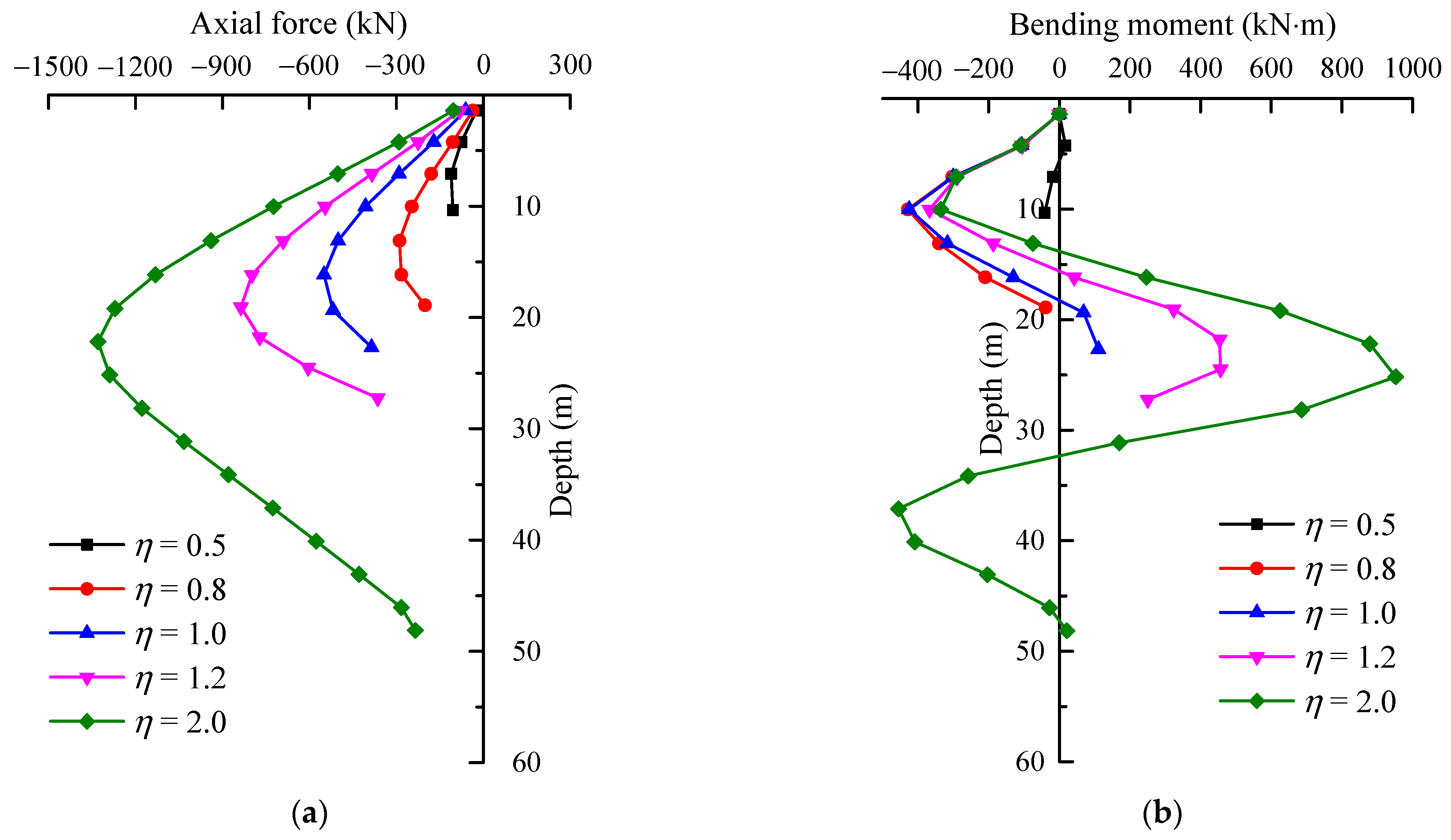
To describe the vertical relative position between the tunnel and the pile, the length-to-depth ratio (η) is used, defined as the ratio of the pile length to the depth of the tunnel axis. A value of η greater than 1 indicates that the pile toe is located below the tunnel axis, referred to as a lower-side pile, whereas a value of η less than 1 indicates that the pile toe lies above the tunnel axis, designated as an upper-side pile. Five distinct length-to-depth ratios were examined in this study: η = 0.5, 0.8, 1.0, 1.2, and 2.0.
Figure 16 illustrates the displacement of piles under different values of η. The pattern of displacement distribution along the pile depth remains consistent across the various ratios examined. The maximum horizontal displacement initially increases with η before subsequently decreasing, whereas the maximum vertical displacement continuously declines as η increases. When η equals 1.0, indicating that the pile toe aligns with the tunnel axis, the horizontal displacement reaches a peak value of 7.16 mm. For η values less than or equal to 1.0, corresponding to short- to medium-length piles relative to the tunnel, the maximum horizontal displacement occurs at the pile toe. Conversely, for η values greater than 1.0, representing long piles, the maximum horizontal displacement occurs at the pile elevation coinciding with the tunnel axis. Notably, long piles exhibit smaller maximum horizontal displacements compared to medium-length piles. This phenomenon is primarily attributed to the fact that shield construction at the tunnel axis exerts the greatest influence on soil disturbance along the pile side, while long piles typically extend into the bedrock, with their ends embedded in zones less affected by such disturbances, resulting in relatively reduced maximum horizontal displacements.
For values of η less than or equal to 1.0, the vertical displacement along the pile shows minimal variation. Shorter piles exhibit increased axial stiffness, which reduces compression caused by axial forces induced by the tunnel and results in more uniform settlement patterns. Additionally, these piles are located above the tunnel axis, where soil settlement tends to be more pronounced, leading to greater vertical displacements. In contrast, when η exceeds 1.0, there is a significant variation in vertical displacement along the pile length. Longer piles develop greater total frictional resistance, and soil disturbance decreases substantially below the tunnel axis. Consequently, with pile toes anchored in zones minimally affected by soil movement, the overall vertical settlement of the pile is reduced.
Figure 17 illustrates the variation in internal forces in pile foundations with respect to different length-to-depth ratios (η). The maximum axial force within the pile foundation increases as the η values increase. This phenomenon is attributed to changes in the pile–soil interaction mechanism caused by disturbances associated with shield tunnel excavation, particularly alterations in the properties and spatial distribution of lateral resistance. Specifically, during shield tunnel excavation, the soil above the tunnel undergoes downward settlement, while the soil beneath the tunnel exhibits rebound behavior.
  • η < 1.0 (Short piles)
For short piles characterized by η < 1, the pile toe is located above the tunnel axis, causing the soil rebound beneath the tunnel to have a relatively minor impact on the pile foundation. Under these conditions, the predominant downward settlement of the surrounding soil induces negative skin friction along the entire length of the pile, which consequently increases the axial force within the pile. However, due to the lack of significant resistance against downward displacement at the pile toe, the peak axial force observed remains relatively low.
  • η = 1.0 (Medium-length piles)
For medium-length piles characterized by η = 1, the pile toes align with the tunnel axis, corresponding to the inflection point in the soil displacement profile. At this location, the downward movement of the upper soil layer induces negative frictional forces, while the rebound of the lower soil layer causes an upward displacement trend at the pile toe relative to the pile shaft, generating positive frictional forces near the pile toe. The simultaneous presence of both positive and negative frictional forces limits the relative displacement between the pile and the surrounding soil, thereby increasing the peak axial force within the pile foundation.
  • η > 1.0 (Long piles)
For long piles with η values greater than 1, the pile toe is located below the tunnel axis and is significantly influenced by soil rebound effects. As a result, the positive frictional forces along the pile shaft are intensified, causing an increase in the peak axial force near the tunnel axis. This enhanced positive friction reduces the relative displacement between the pile and the surrounding soil, thereby contributing to the elevated axial force observed in the pile foundation.
The bending moments along the vertical axis of the pile display approximately consistent variation patterns across different length-to-depth ratios. Shorter piles, due to their reduced lengths, experience relatively minor horizontal effects induced by tunnel excavation, resulting in lower bending moments. As the pile length increases, the maximum bending moment correspondingly rises. This behavior primarily stems from the relative position of the tunnel burial depth to the pile toe. Specifically, when the pile toe is located below the tunnel axis, the pile foundation undergoes a greater bending moment at the tunnel axis; conversely, if the pile toe lies above the tunnel axis, the resulting bending moment is comparatively smaller.

5.2. Horizontal Relative Position of Tunnel–Pile Foundations

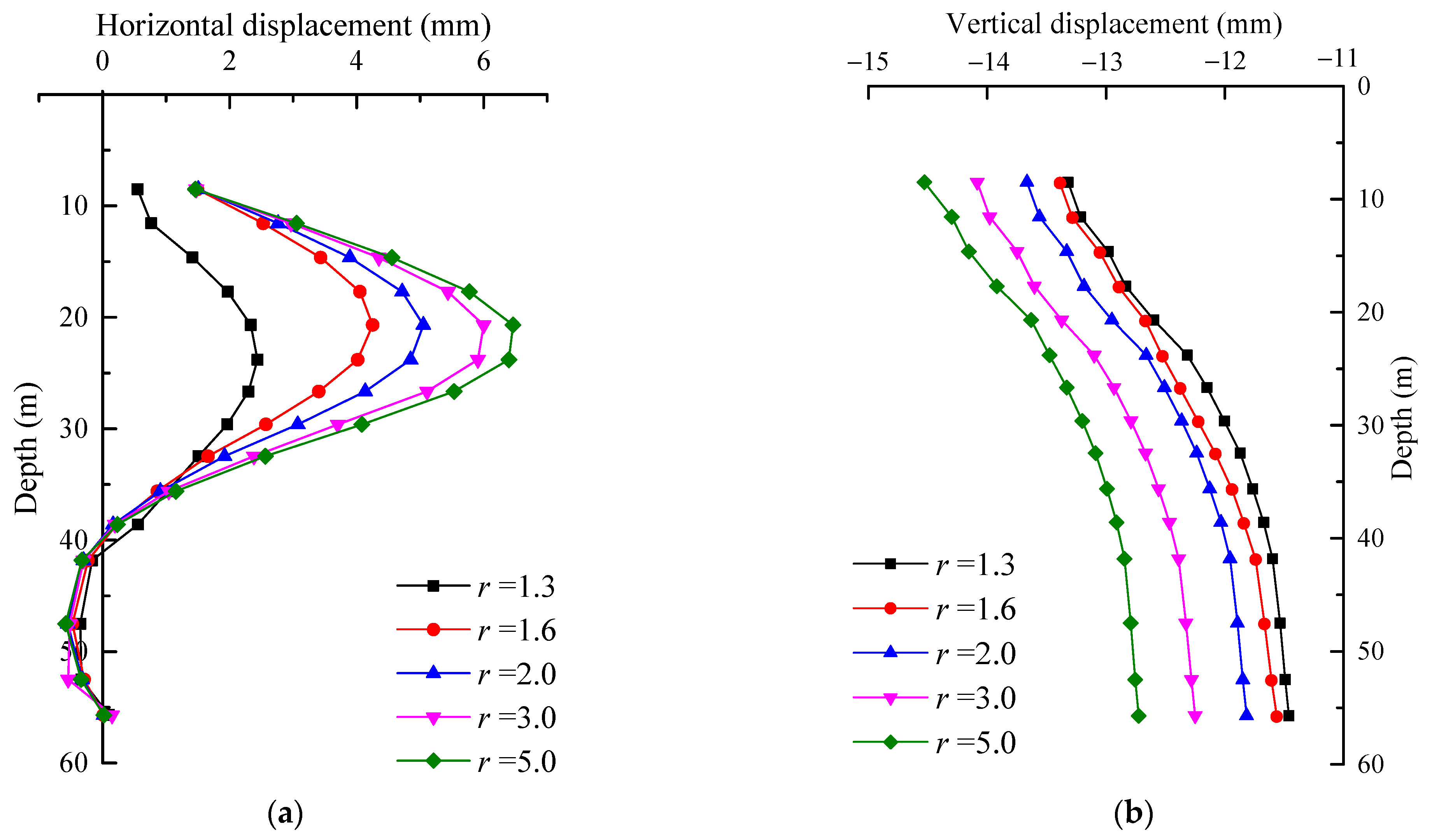
To comprehensively account for the tunnel outer diameter and pile diameter, the axial-to-clearance ratio (r) is introduced, defined as the ratio of the axial distance to the clear distance between the tunnel and pile centerlines. This ratio describes the horizontal relative position between the tunnel and pile. A higher r indicates closer proximity, while an r approaching 1 signifies greater separation. Five axial-to-clearance ratios were analyzed to assess the horizontal influence of shield tunneling on adjacent piles: r = 1.3, 1.6, 2.0, 3.0, and 5.0. In order to eliminate the influence of the foundation treatment in the vicinity of the bridge, the pile head is set below the foundation treatment layer; that is, the pile head is 8.5 m below the ground surface.
Figure 18 presents the pile displacement under varying axial-to-clearance ratios. The distribution pattern of displacement along the pile remains consistent across all ratios. Vertical displacement decreases gradually from the pile head to the toe, while the maximum horizontal displacement occurs near the tunnel axis. As the axial-to-clearance ratio (r) increases, the clear distance between the tunnel and pile decreases, leading to an increase in both horizontal and vertical pile displacements. The vertical displacement at the pile head increased from 13.32 mm to 14.64 mm, representing a relatively modest increase of approximately 10%. At r = 1.3, the maximum horizontal displacement was only 2.4 mm, indicating that the tunnel excavation had a minimal effect on the pile in the horizontal direction at this separation.
Figure 19 illustrates the variation in pile internal forces under different axial-to-clearance ratios. The trends in axial force and bending moment distribution along the pile are similar for all ratios, with peak values occurring near the tunnel axis. As the axial-to-clearance ratio (r) increases, both the axial force and bending moment of the pile increase. The maximum bending moment increased significantly from 456.34 kN·m to 1707.83 kN·m, a 2.7-fold increase. The maximum axial force also increased by 3.4 times. This indicates that the internal forces of the pile foundation are significantly influenced by the distance between the tunnel and the pile foundation.

5.3. Stiffness Coefficient of Pile Foundations

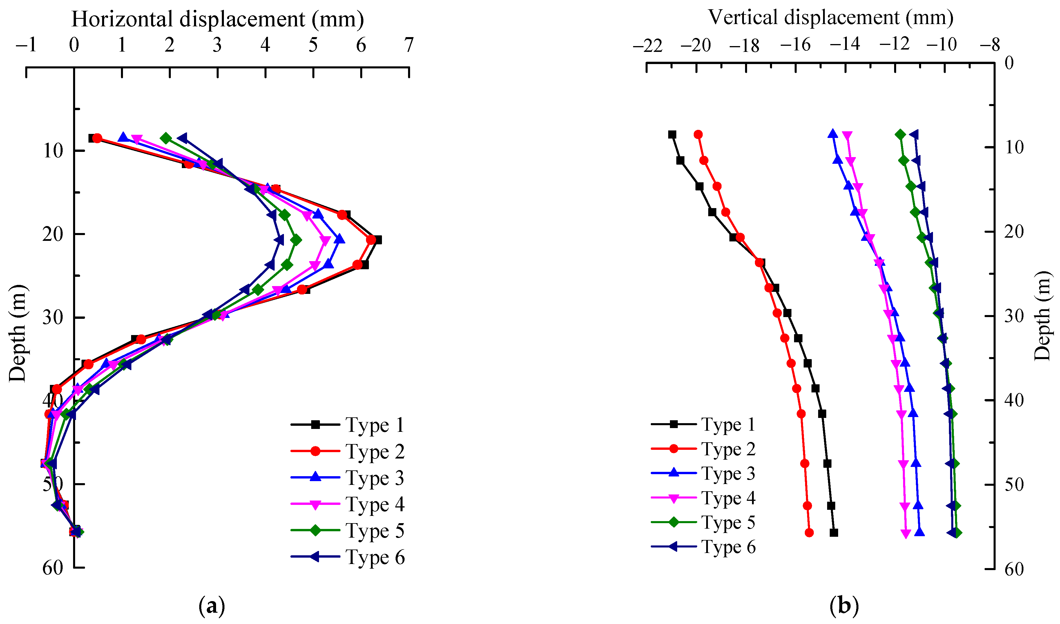
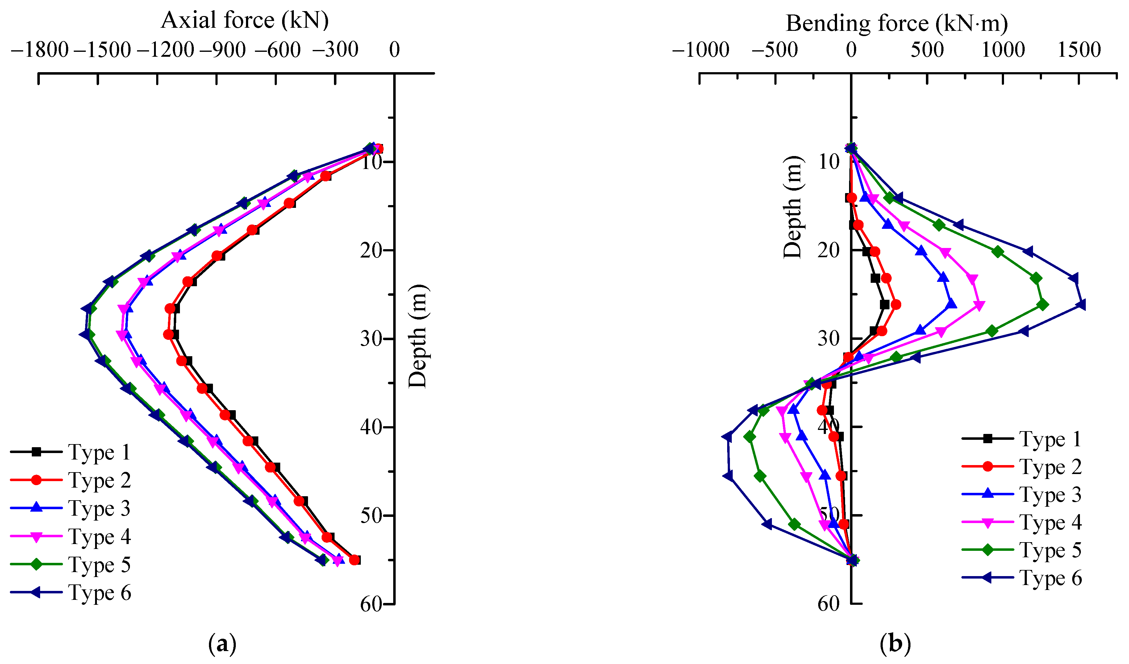
To investigate the influence of pile stiffness on deformation behavior and internal force distribution, the pile stiffness coefficient (δ) is defined as δ = EA/L, where E represents the Young’s modulus of the pile material, A denotes the cross-sectional area, and L corresponds to the pile length. A higher δ value indicates a stiffer pile with greater resistance to deformations caused by tunneling activities, whereas a lower δ signifies increased susceptibility to construction-related disturbances. Six distinct pile types, characterized by varying stiffness coefficients, were analyzed, and their respective parameters are presented in Table 4.
Figure 20 illustrates the displacement behavior of piles subjected to varying stiffness coefficients. Both the maximum horizontal and vertical displacements decrease as the stiffness coefficient δ increases, indicating that enhanced pile stiffness effectively limits deformation. A comparison between Type 1 and Type 3 piles shows that increasing the pile diameter results in approximately a 30% reduction in vertical displacement at the pile head, whereas increasing the Young’s modulus alone yields only a 5% reduction. This finding suggests that vertical displacement is predominantly influenced by pile diameter. Larger diameters increase the pile–soil contact area, thereby raising δ and improving both bearing capacity and resistance to vertical deformation. Additionally, differential settlement between the pile head and toe is affected by the pile’s Young’s modulus. Specifically, a lower Young’s modulus corresponds to greater compressive deformation within the pile and consequently larger differential settlement between the pile top and bottom. Conversely, a higher Young’s modulus reduces self-compression deformation, resulting in smaller differential settlement along the pile length.
Figure 21 illustrates the change in internal forces in the pile with different stiffness coefficient (δ). As pile stiffness increases, the axial force on the pile also increases. Analysis shows that both the pile diameter and Young’s modulus increase with pile stiffness, although the increase in Young’s modulus is relatively small. Changes in pile diameter have minimal impact on the development of pile side friction resistance. Increasing the pile diameter primarily raises the total frictional resistance along the pile side, while reducing the frictional resistance borne by the pile toe, which leads to an increase in the maximum axial force experienced by the pile foundation. As the pile stiffness coefficient increases, the bending moment in the pile also increases. According to the principle of pile–soil deformation compatibility, additional deformation and stress in the soil surrounding the pile are transferred to the pile body with higher stiffness, resulting in an increased bending moment in the pile.

5.4. Grouting Pressures

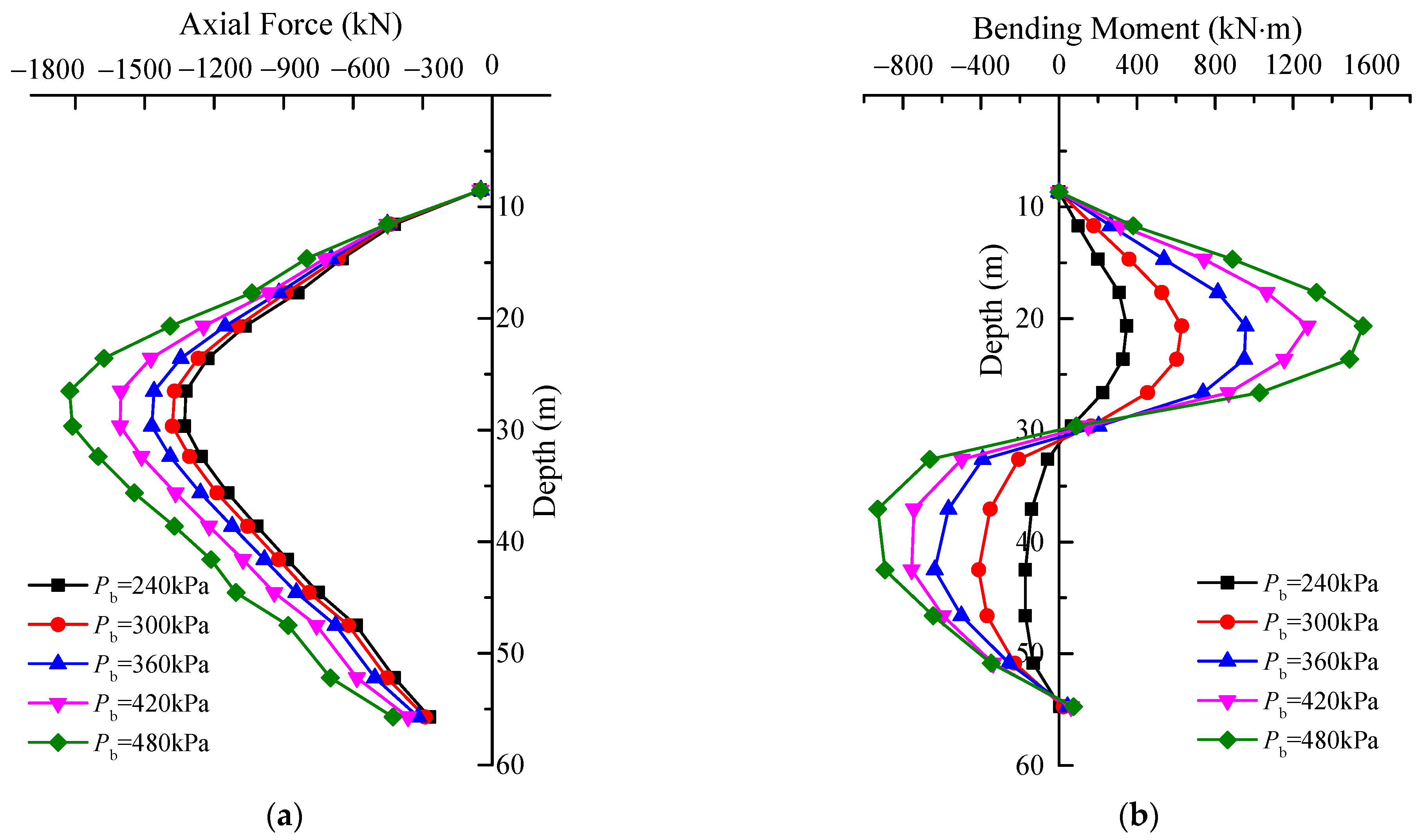
Figure 22 shows the variation in pile displacement under different grouting pressures (Pb). As can be seen from the figure, both the horizontal and vertical displacements of the pile increase with higher grouting pressure. The horizontal displacement of the pile first increases and then decreases along the pile depth, reaching a maximum value of 7.16 mm near the tunnel axis. This occurs because the grouting pressure applied behind the shield exerts a squeezing effect on the surrounding soil near the tunnel axis, leading to significant horizontal displacement of the pile in this region. The maximum settlement of 14.76 mm occurs at the pile head, which is primarily attributed to the fact that the pile is rock-socketed and the influence of grouting pressure on the portion of the pile below the tunnel is relatively limited.
The variation in internal forces in the pile under different grouting pressures is shown in Figure 23. The distribution of internal forces along the pile remains consistent across different grouting pressures, while the magnitude of these forces increases with higher pressure. The maximum internal force consistently occurs near the tunnel axis. During shield tunneling, the application of grouting pressure compensates for some of the stress loss in the ground caused by excavation. However, increased grouting pressure also introduces additional disturbance to the surrounding soil, thereby increasing the internal forces in adjacent piles. The soil near the tunnel axis experiences the most significant disturbance from grouting pressure, resulting in the highest internal forces in the pile at this location. Therefore, it is essential to carefully control both the grouting pressure and volume during construction to mitigate the impact of shield tunneling on adjacent piles.

6. Discussion

6.1. Findings

The finite model and parametric results demonstrate that the influence of tunnel excavation on the behavior of adjacent bridge pile foundations can be divided into three distinct phases:
  • The initial phase occurs before the shield tunneling construction reaches the pile foundation site. During this stage, the pile foundations are primarily affected by the propagation of soil pressure from the excavation face, resulting in slight deformations that are mainly directed away from the tunnel boundary.
  • The second phase occurs as the shield tunneling process reaches and advances beyond the pile foundation. During this stage, the soil strata adjacent to the pile foundation on the tunnel side experience unloading, resulting in a significant reduction in the lateral constraint forces acting on the pile. Consequently, the pile foundation is subjected to a complex interaction of forces, including soil pressure from the excavation face, frictional resistance between the shield machine and the surrounding soil, and grouting pressure at the shield tail. These combined effects induce substantial bending deformation of the pile foundation toward the tunnel side, with internal forces and deformations reaching their maximum values near the tunnel axis. This observation aligns well with the findings reported by Zhang et al. [39]. Notably, the shield machine’s proximity within 1D of the foundation produces the most pronounced effects.
  • The final stage involves the shield machine advancing beyond the pile foundation, during which the pile is primarily influenced by displacement effects caused by the grouting pressure at the shield tail. This results in the stabilization of internal forces and deformations within the pile. Throughout the tunnel construction process, the upper soil layer surrounding the pile experiences significant settlement, exerting downward negative skin friction along the pile shaft. Meanwhile, the pile toe is constrained by the deeper, less-displaced firm soil stratum. This combination of “pulling from above and supporting from below” places the pile in a state of tension and compression, resulting in greater settlement at the pile head than at the pile toe. In general, when the pile response is dominated by external soil displacement, the vertical displacement at the pile head is typically larger than that at the base. The development of vertical pile displacement due to soil settlement and skin friction has also been validated through a numerical simulation study carried out by Nabil et al. [40]. In summary, internal forces and displacements within the pile foundation progressively increase in tandem with the advancement of the shield tunneling process.
The vertical position of the pile toe relative to the tunnel axis significantly influences the pile foundation’s response to tunneling. When the pile toe is located above the tunnel axis, soil settlement above the tunnel is pronounced, resulting in substantial settlement of the pile foundation. Under these conditions, the impact of tunnel excavation is relatively modest: the pile predominantly experiences negative skin friction, internal forces within the pile remain low, and the maximum horizontal displacement occurs at the pile toe. Conversely, when the pile toe aligns with the tunnel axis, the effect of tunnel excavation intensifies. Soil rebound beneath the tunnel causes the soil surrounding the pile toe to rise relative to the adjacent soil, generating positive skin friction along the pile shaft. This scenario is characterized by increased internal forces within the pile foundation, a peak in horizontal displacement, and a reduction in vertical displacement. When the pile toe lies below the tunnel axis, the rebound effect of the soil beneath the tunnel becomes more pronounced, further amplifying the impact of tunnel excavation on the pile foundation. In this case, the maximum horizontal displacement is observed along the pile segment corresponding to the tunnel axis. The observed deformation amounts under different vertical relative positions of tunnel–pile foundations are consistent with the numerical simulation results reported in Nabil et al. [40].
The influence of shield tunneling construction on adjacent pile foundations depends on variations in the pile foundation’s stiffness coefficient and the spatial relationship between the pile foundation and the tunnel. An increase in the pile foundation’s stiffness enhances its bearing capacity, improves its resistance to deformation, and consequently reduces the extent of pile deformation. As the horizontal clearance between the tunnel and the pile foundation increases, the disturbance to the surrounding soil caused by tunnel excavation diminishes, leading to a corresponding decrease in the internal forces and displacements experienced by the pile foundation. Notably, beyond a certain threshold of horizontal clearance, the horizontal influence of tunnel excavation on the pile foundation becomes negligible. Moreover, grouting pressure can compensate for a portion of the ground stress loss induced by shield tunneling, while excessively high pressure may cause additional disturbance to the surrounding soil, adversely affecting adjacent piles.
In summary, during shield tunneling construction, careful attention must be paid to the settlement of pile heads located within a distance equal to 1D from the tunnel, as well as to the horizontal deformation and variations in internal forces of piles situated near the tunnel axis. A comprehensive analysis of the effects of shield tunneling on piles should consider factors such as pile stiffness and the spatial relationship between the piles and the tunnel. In addition, grouting pressure and volume must be carefully controlled during construction to minimize adverse effects. Where appropriate, mitigation strategies should be implemented to control pile deformation.

6.2. Limitations

While this study provides valuable insights into the responses of pile foundations to adjacent shield tunneling, it is imperative to acknowledge several limitations inherent in the numerical modeling approach adopted.
Firstly, the constitutive models employed to represent material behavior introduce certain simplifications. The use of the Mohr–Coulomb criterion for the soil mass, while computationally efficient and widely accepted for preliminary analyses, does not capture the complex stress-path-dependent behavior of soils. Notably, it fails to account for the non-linear stiffness at small strains, soil anisotropy, and the stress-dependent reduction in stiffness upon shearing. Similarly, the assumption of linear elastic behavior for both the concrete piles and the tunnel lining, although common, is a simplification. This model ignores potential cracking in concrete or the plastic yielding of reinforcement under excessive loading, which could lead to an overestimation of the system’s stiffness and an underestimation of permanent deformations.
Secondly, this study did not consider time-dependent effects, which could significantly influence the long-term interaction mechanism. The consolidation process of the surrounding clayey soils, triggered by tunneling-induced excess pore water pressures, was not simulated. Consequently, the model potentially overlooks the long-term creep settlement of the soil and the corresponding evolution of internal forces in the piles over time.
Finally, the inherent uncertainties in the actual construction process pose another limitation. Although a simplified, idealized construction sequence was simulated, the real-world tunneling process involves complex, variable factors such as exact face support pressure fluctuations and potential workmanship issues. These uncertainties were not stochastically modeled, meaning the analysis presents a deterministic outcome that may not fully represent the spectrum of possible responses.
Despite these limitations, the current model successfully captures the fundamental mechanisms of soil–pile–tunnel interaction and provides a robust qualitative and quantitative assessment of key influencing factors. Future research efforts will focus on implementing advanced constitutive models (e.g., Hypoplasticity or Modified Cam-Clay) to better represent soil behavior, incorporating coupled hydro-mechanical analyses to simulate consolidation, and performing more systematic parametric studies on construction variables to account for operational uncertainties.

7. Conclusions

This paper presents a finite element model of a shield tunnel intersecting the Haiqin Bridge pile foundation within the Guangzhou–Zhuhai Intercity Railway project. It analyzes the impact of shield tunnel construction on the adjacent bridge pile foundation. This study investigates how the relative position between the tunnel and pile foundation, along with the pile foundation’s stiffness coefficient, affects the structural performance of the bridge pile foundation. Subsequently, the following significant conclusions have been drawn:
  • The published centrifuge test results validate the accuracy of the finite element modeling method used in this paper, which effectively simulates changes in the structural performance of adjacent pile foundations at various stages of tunnel construction.
  • Finite element simulation results indicate that tunnel shield construction causes nearby bridge pile foundations to bend and deform toward the tunnel side. It should be noted that the bridge pile foundations experience the greatest horizontal displacement and internal forces in the same plane as the tunnel. The tunnel shield construction has the most significant impact on the internal forces and displacement of pile foundations within a range of 1D before and after the pile foundation location.
  • As the vertical length-to-depth ratio (η) increases, indicating elongation of the pile length, the impact of tunnel construction on nearby pile foundations varies. When the pile toe is located above the tunnel axis burial depth (η < 1), the pile foundation primarily experiences settlement accompanied by negative frictional forces, with the greatest horizontal displacement observed at the pile toe. When the pile toe aligns with the tunnel axis (η = 1), the pile foundation begins to exhibit positive frictional forces, and the horizontal displacement reaches its maximum magnitude. When the pile toe extends below the tunnel axis burial depth (η > 1), the positive frictional forces within the pile foundation intensify further, while the maximum horizontal displacement decreases and shifts to the depth corresponding to the tunnel axis. Moreover, as the pile length increases, internal forces within the pile foundation amplify, whereas the overall settlement of the pile foundation decreases.
  • The distribution patterns of internal forces and displacements along the pile foundation remain consistent subjected to different horizontal axial-to-clearance ratios (r). A decrease in the horizontal axial-to-clearance ratio (r) corresponds to a reduction in the internal forces and displacements experienced by the pile foundation. Furthermore, once the horizontal clearance reaches a specific threshold, tunnel construction no longer affects the structural behavior of the pile foundation.
  • As the pile stiffness coefficient increases, the maximum displacement of the pile decreases, while the internal force in the pile shaft increases. Both the pile diameter and Young’s modulus affect the pile behavior similarly to the stiffness coefficient. However, the pile diameter has a greater influence compared to Young’s modulus.

Author Contributions

Conceptualization, H.L.; methodology, Z.C.; software, J.W.; validation, W.D.; formal analysis, B.L.; investigation, C.H.; resources, Z.C.; data curation, C.H.; writing—original draft preparation, C.H. and J.W.; writing—review and editing, B.L.; visualization, C.H.; supervision, W.D.; project administration, H.L.; funding acquisition, C.H. All authors have read and agreed to the published version of the manuscript.

Funding

This research was funded by the Science and Technology Planning Project of Guangzhou Municipal Construction Group Co., Ltd. (Grant No. [2024]-KJ018).

Data Availability Statement

The original contributions presented in this study are included in the article. Further inquiries can be directed to the corresponding author.

Conflicts of Interest

Authors Cong He, Huan Liang and Zhongzhang Chen were employed by the company Guangzhou Municipal Engineering Group Ltd. The remaining authors declare that the research was conducted in the absence of any commercial or financial relationships that could be construed as a potential conflict of interest.

References

  1. Mao, J.H.; Yuan, D.J.; Jin, D.L.; Zeng, J.F. Optimization and application of backfill grouting material for submarine tunnel. Constr. Build. Mater. 2020, 265, 120281. [Google Scholar] [CrossRef]
  2. Liu, C.; Li, J.; Zhang, Z.; Li, P.; Cui, J.; Liu, H.; Yang, Y. Model tests on tail-grouting process during URUP shield tunneling in soft soil. Tunn. Undergr. Space Technol. 2020, 103, 103451. [Google Scholar] [CrossRef]
  3. Xu, Q.; Xu, S.; Li, Y.; Zhang, Y.; Tian, H.; Zhao, M. Deformation control strategies for shield tunnel underpassing viaduct of high-speed railway: A case study. Chin. J. Eng. Res. 2023, 13, 390–398. [Google Scholar] [CrossRef]
  4. Yan, B.; Wang, R.; Wang, Y. Deformation of adjacent buildings and ground settlement induced by shield construction of three-line small-spacing tunnels. Alex. Eng. J. 2023, 79, 237–251. [Google Scholar] [CrossRef]
  5. Wu, C.; Zhu, Z. Analytical Method for Evaluating the Ground Surface Settlement Caused by Tail Void Grouting Pressure in Shield Tunnel Construction. Adv. Civ. Eng. 2018, 3729143. [Google Scholar] [CrossRef]
  6. Xie, X.; Yang, Y.; Ji, M. Analysis of ground surface settlement induced by the construction of a large-diameter shield-driven tunnel in Shanghai, China. Tunn. Undergr. Space Technol. 2016, 51, 120–132. [Google Scholar] [CrossRef]
  7. Bhattacharya, S.; Demirci, H.E.; Nikitas, G.; Prakhya, G.; Lombardi, D.; Alexander, N.; Aleem, M.; Amani, S.; Mylonakis, G. Physical modeling ofinteractionproblems in geotechnical engineering. In Modeling in Geotechnical Engineering; Academic Press: Cambridge, MA, USA, 2021; pp. 205–256. [Google Scholar] [CrossRef]
  8. Fu, J.; Yang, J.; Zhang, X.; Klapperich, H.; Abbas, S.M. Response of the ground and adjacent buildings due to tunnelling in completely weathered granitic soil. Tunn. Undergr. Space Technol. 2014, 43, 377–388. [Google Scholar] [CrossRef]
  9. Wang, N.; Jiang, Y.; Geng, D.; Huang, Z.; Ding, H. Numerical Investigation of the Combined Influence of Shield Tunneling and Pile Cutting on Underpinning Piles. Front. Earth Sci. 2022, 10, 896634. [Google Scholar] [CrossRef]
  10. Liang, F.; Zhang, H.; Yang, K. A variational solution for nonlinear response of laterally loaded piles with elasto-plastic winkler spring model. KSCE J. Civ. Eng. 2015, 19, 74–80. [Google Scholar] [CrossRef]
  11. Zhang, Z.; Huang, M.; Jiang, Y.; Wang, W. Simplified solution for tunnel-soil-pile interaction in Pasternak’s foundation model. Tunn. Undergr. Space Technol. 2018, 78, 146–158. [Google Scholar] [CrossRef]
  12. Zhang, Z.; Zhang, C.; Jiang, K.; Wang, Z.; Jiang, Y.; Zhao, Q.; Lu, M. Analytical Prediction for Tunnel-Soil-Pile Interaction Mechanics based on Kerr Foundation Model. KSCE J. Civ. Eng. 2019, 23, 2756–2771. [Google Scholar] [CrossRef]
  13. Jia, H.; Wang, N.; Ding, H.; Guan, L. Impact of Tunneling on Adjacent Piles Based on the Kerr Foundation Model Considering the Influence of Lateral Soil. Buildings 2023, 13, 2548. [Google Scholar] [CrossRef]
  14. Wu, T.; Gao, Y.; Huang, C.; Jin, A.; Zhou, Y.; Li, J. Horizontal mechanical responses of single pile induced by adjacent tunneling considering the effect of multiple factors based on Timoshenko Beam-Kerr foundation model. Appl. Math. Model. 2025, 140, 115885. [Google Scholar] [CrossRef]
  15. Wang, C.; Zou, J.; Shu, D. A Method for Calculating the Deformation of Existing Bridge Pile Foundations Caused by the Oblique Crossing of Shield Tunnels. Int. J. Geomech. 2025, 25, 04025130. [Google Scholar] [CrossRef]
  16. Zhou, J.; Han, K.; Chen, W. Study on Influence Mechanism of Tunnel Construction on Adjacent Pile Foundation and Resilience Assessment. Buildings 2024, 14, 2818. [Google Scholar] [CrossRef]
  17. Ng, C.W.W.; Lu, H.; Peng, S.Y. Three-dimensional centrifuge modelling of the effects of twin tunnelling on an existing pile. Tunn. Undergr. Space Technol. 2013, 35, 189–199. [Google Scholar] [CrossRef]
  18. Soomro, M.A.; Mangi, N.; Mangnejo, D.A.; Memon, N.A. 3D centrifuge and numerical modelling of lateral responses of a vertical loaded pile group to twin stacked tunnels. Eur. J. Environ. Civ. Eng. 2021, 26, 5517–5544. [Google Scholar] [CrossRef]
  19. Soomro, M.A.; Ng, C.W.W.; Memon, N.A.; Bhanbhro, R. Lateral behaviour of a pile group due to side-by-side twin tunnelling in dry sand: 3D centrifuge tests and numerical modelling. Comput. Geotech. 2018, 101, 48–64. [Google Scholar] [CrossRef]
  20. He, S.; Lai, J.; Li, Y.; Wang, K.; Wang, L.; Zhang, W. Pile group response induced by adjacent shield tunnelling in clay: Scale model test and numerical simulation-ScienceDirect. Tunn. Undergr. Space Technol. 2022, 120, 104039. [Google Scholar] [CrossRef]
  21. Su, J.; Pan, Y.; Niu, X.; Zhang, C. Effect of shield tunneling on adjacent pile foundations in water-rich strata. Transp. Geotech. 2025, 52, 101557. [Google Scholar] [CrossRef]
  22. Guo, C.; Yue, H.; Tao, Y.; Liu, G.; Kong, F.; Lu, D.; Du, X. Mechanical response of pile group and stratum induced by shallow tunneling based on the model test. Tunn. Undergr. Space Technol. Inc. Trenchless Technol. Res. 2025, 159, 106480. [Google Scholar] [CrossRef]
  23. Kitiyodom, P.; Matsumoto, T. A simplified analysis method for piled raft foundations in non-homogeneous soils. Int. J. Numer. Anal. Methods Geomech. 2003, 27, 85–109. [Google Scholar] [CrossRef]
  24. Kitiyodom, P.; Matsumoto, T.; Kawaguchi, K. A simplified analysis method for piled raft foundations subjected to ground movements induced by tunnelling. Int. J. Numer. Anal. Methods 2005, 29, 1485–1507. [Google Scholar] [CrossRef]
  25. Asgarkhani, N.; Kazemi, F.; Jankowski, R. Machine-learning based tool for seismic response assessment of steel structures including asonry infill walls and soil-foundation-structure interaction. Comput. Struct. 2025, 317, 107918. [Google Scholar] [CrossRef]
  26. Lee, G.T.K.; Ng, C.W.W. Effects of advancing open face tunneling on an existing loaded pile. J. Geotech. Geoenviron. Eng. 2005, 131, 193–201. [Google Scholar] [CrossRef]
  27. Yang, X.J.; Deng, F.H.; Wu, J.J.; Liu, J.; Wang, F.Q. Response of carrying capacity of piles induced by adjacent Metro tunneling. Min. Sci. Technol. 2009, 19, 176–181. [Google Scholar] [CrossRef]
  28. Jongpradist, P.; Kaewsri, T.; Sawatparnich, A.; Suwansawat, S.; Youwai, S.; Kongkitkul, W.; Sunitsakul, J. Development of tunnelinginfluence zones for adjacent pile foundations by numerical analyses. Tunn. Undergr. Space Technol. 2013, 34, 96–109. [Google Scholar] [CrossRef]
  29. Liu, C.; Zhang, Z.X.; Regueiro, R.A. Pile and pile group response to tunnelling using a large diameter slurry shield-Case study in Shanghai. Comput. Geotech. 2014, 59, 21–43. [Google Scholar] [CrossRef]
  30. Boonyarak, T.; Phisitkul, K.; Ng, C.W.W.; Teparaksa, W.; Aye, Z.Z. Observed ground and pile group responses due to tunneling in Bangkok stiff clay. Can. Geotech. J. 2014, 51, 479–495. [Google Scholar] [CrossRef]
  31. Soomro, M.; Yi, H.; Ng, C.W.W.; Hu, L.; Peng, S. Load transfer mechanism in pile group due to single tunnel advancement in stiff clay. Tunn. Undergr. Space Technol. 2015, 45, 63–72. [Google Scholar] [CrossRef]
  32. Zidan, F.A.; Ramadan, M.O.O. Three dimensional numerical analysis of the effects of tunnelling near piled structures. KSCE J. Civ. Eng. 2015, 19, 917–928. [Google Scholar] [CrossRef]
  33. Li, H.J.; Tong, L.Y.; Liu, S.Y. Multistage-based evaluation of tunnelling effects onthe skin friction of adjacent building piles in layered media. Structures 2021, 32, 96–105. [Google Scholar] [CrossRef]
  34. Dai, X.; Cai, J.; Diao, Y.; Huo, H.; Xu, G. Influence of tunnelling on the deformation of the overlying excavation bracing system and analysis of countermeasures. Comput. Geotech. 2021, 134, 104089. [Google Scholar] [CrossRef]
  35. Huang, K.; Sun, Y.; Huang, X.; Li, Y.; Jiang, M.; Liu, R. Effects of different construction sequences on ground surface settlement and displacement of single long pile due to twin paralleled shield tunneling. Adv. Civ. Eng. 2021, 1–14. [Google Scholar] [CrossRef]
  36. Huang, K.; Sun, Y.W.; Zhou, D.Q.; Li, Y.J.; Jiang, M.; Huang, X.Q. Influence of water-rich tunnel by shield tunneling on existing bridge pile foundation in layered soils. J. Central South Univ. 2021, 28, 2574–2588. [Google Scholar] [CrossRef]
  37. Ayasrah, M.; Qiu, H.; Zhang, X.; Andrianov, I.V. Influence of cairo metro tunnel excavation on pile deep foundation of the adjacent underground structures: Numerical study. Symmerty 2021, 13, 426. [Google Scholar] [CrossRef]
  38. Lv, J.; Lin, D.; Wu, W.; Huang, J.; Li, Z.; Fu, H.; Li, H. Mechanical Responses of Slurry Shield Underpassing Existing Bridge Piles in Upper-Soft and Lower-Hard Composite Strata. Buildings 2022, 12, 1000. [Google Scholar] [CrossRef]
  39. Zhang, S.; Zhang, X.; Ning, X.; Lu, H.; Jiang, M.; Wei, S.; Xiao, X. Effect of Shield-Tunnel Construction on the Horizontal Response of Adjacent Piles in a Silty Layer. Buildings 2023, 13, 2455. [Google Scholar] [CrossRef]
  40. Nabil, M.H.; Tamir, A.; Abderahim, B. Three-dimensional numerical analyses of pile responses to tunneling-induced ground movements in bilayer soil. World J. Eng. 2024, 21, 71–90. [Google Scholar] [CrossRef]
  41. Jiao, N.; Ding, J.; Liao, Z.; Wan, X.; Gao, P. Impact of Double Shield Tunnel Construction on Adjacent Pile Foundation in Silty Fine Sand Strata. J. Perform. Constr. Facil. 2025, 39. [Google Scholar] [CrossRef]
  42. GB/T 50783-2012; Technical Code for Composite Foundation. China Planning Press: Beijing, China, 2012.
  43. Liu, W.; Zhao, L.; Yao, X.C.; Zheng, H.A.; Liu, W.L. Impact of Shield Tunnel Construction on Adjacent Railway Bridge: Protective Measures and Deformation Control. Buildings 2024, 14, 3024. [Google Scholar] [CrossRef]
  44. Zhang, Y.; Yin, Z.; Xu, Y. Analysis on three-dimensional ground surface deformations due to shield tunnel. Chin. J. Rock Mech. Eng. 2002, 21, 388–392. [Google Scholar]
  45. Franzius, J.N.; Potts, D.M. Influence of mesh geometry on three-dimensional finite-element analysis of tunnel excavation. Int. J. Geomech. 2005, 5, 256–266. [Google Scholar] [CrossRef]
  46. Mair, R.J.; Taylor, R.N.; Bracegirdle, A. Subsurface settlement profiles above tunnels in clays. Geotechnique 1993, 43, 315–320. [Google Scholar] [CrossRef]
  47. Ren, R.; Zhong, Y.J.; Xu, S.S.; Ma, E.L.; Xie, Y. Numerical Simulation on Safety Influence of Shield TunnelingSide Crossing on Adjacent High Buildings of Steel Tower Atop. Highway 2018, 12, 318–324. [Google Scholar]
  48. Lin, C.; Jiang, R.; Xiao, S.; Wang, Z. Mechanism of influences of shield construction nearby friction pile foundation on its bearing capacity and its controlling techniques. Chin. J. Geotech. Eng. 2023, 45, 241–246. [Google Scholar] [CrossRef]
  49. Zhang, Z.G.; Huang, M.S.; Wang, W.D. Additional stresses of disturbed soils induced by shield tunneling based on fictitious force method. Chin. J. Geotech. Eng. 2014, 36, 1235–1242. [Google Scholar] [CrossRef]
  50. Cao, S.; Qian, D.L.; Wei, X.Y.; Cheng, H.; Ma, X.F. Influence of deep foundation pit excavation on underlying metro tunnel and control measures. J. Hefei Univ. Technol. 2014, 37, 1479–1482. [Google Scholar] [CrossRef]
  51. Poulos, H.G.; Chen, L.T. Pile response due to excavation-induced lateral soil movement. J. Geotech. Geoenvironmental Eng. ASCE 1997, 123, 94–99. [Google Scholar] [CrossRef]
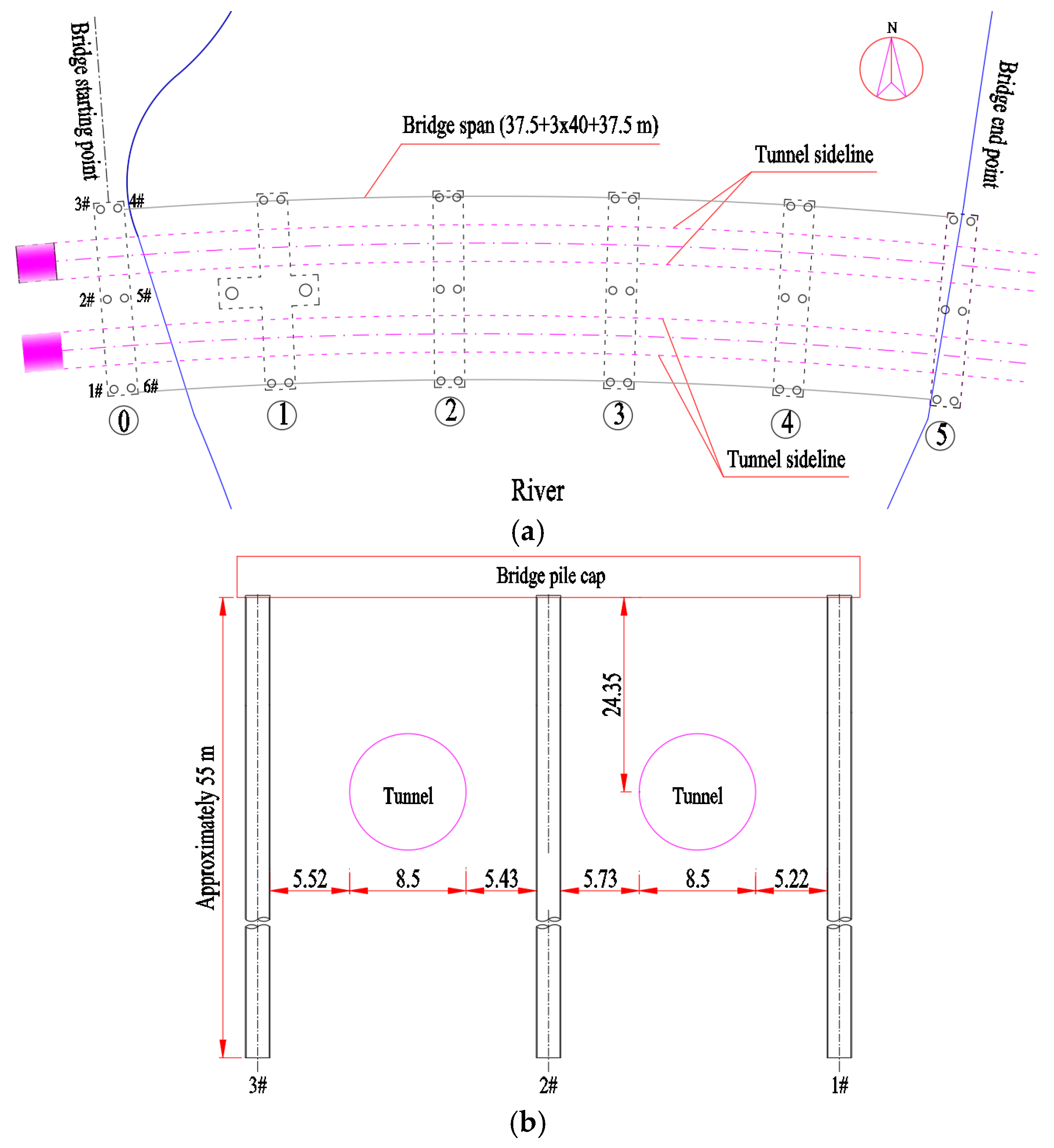
Figure 1. The positional relationship between the tunnel and the pile. (a) Diagram showing the overall plane. (b) Diagram showing the 0# abutment elevation (unit: m).
Buildings 15 03263 g001
Figure 2. Finite element model mesh diagram.
Buildings 15 03263 g002
Figure 3. Simplified schematic diagram of shield tunnel construction.
Buildings 15 03263 g003
Figure 4. The overall numerical model of centrifugal test.
Buildings 15 03263 g004
Figure 5. Comparative of ground surface settlement.
Buildings 15 03263 g005
Figure 6. Comparison of internal pile forces. (a) Pile bending moment distribution. (b) Pile axial force distribution.
Buildings 15 03263 g006
Figure 7. The plane relationship of shield excavation face and pile (m).
Buildings 15 03263 g007
Figure 8. Tunnelling-induced horizontal displacement on pile.
Buildings 15 03263 g008
Figure 9. Horizontal displacement variation in pile at tunnel axis with tunneling.
Buildings 15 03263 g009
Figure 10. Tunnelling-induced vertical displacement on pile.
Buildings 15 03263 g010
Figure 11. Vertical displacement variation in pile head with tunneling.
Buildings 15 03263 g011
Figure 12. Tunnelling-induced axial force on pile.
Buildings 15 03263 g012
Figure 13. Axial force variation in pile at tunnel axis with tunneling.
Buildings 15 03263 g013
Figure 14. Tunneling-induced bending moment on pile.
Buildings 15 03263 g014
Figure 15. Bending moment variation in pile at tunnel axis with tunneling.
Buildings 15 03263 g015
Figure 16. Influence of tunnel–pile vertical length-to-depth ratio (η) on displacement of pile. (a) Horizontal displacement. (b) Vertical displacement.
Buildings 15 03263 g016
Figure 17. Influence of tunnel–pile vertical length-to-depth ratio (η) on internal force of pile. (a) Axial force. (b) Bending moment.
Buildings 15 03263 g017
Figure 18. Influence of tunnel–pile horizontal axial-to-clearance ratio (r) on displacement of pile. (a) Horizontal displacement. (b) Vertical displacement.
Buildings 15 03263 g018
Figure 19. Influence of tunnel–pile horizontal axial-to-clearance ratio (r) on internal force of pile. (a) Axial force. (b) Bending moment.
Buildings 15 03263 g019
Figure 20. Influence of stiffness coefficient on displacement of pile. (a) Horizontal displacement. (b) Vertical displacement.
Buildings 15 03263 g020
Figure 21. Influence of stiffness coefficient on internal force of pile. (a) Axial force. (b) Bending moment.
Buildings 15 03263 g021
Figure 22. Influence of the grouting pressures on displacement of pile. (a) Horizontal displacement. (b) Vertical displacement.
Buildings 15 03263 g022
Figure 23. Influence of the grouting pressures on internal force of pile. (a) Axial force. (b) Bending moment.
Buildings 15 03263 g023
Table 1. Soil basic physical property index.
CategoriesDepth/mUnit Weight/kN·m−3Compression Modulus/MPaPoisson’s RatioCohesion/kPaInternal Friction/°
Artificial fill (after treatment)8.51825.30.32035
Silt9.216.64.660.422.92.8
Clay23.917.94.660.416.323.3
Coarse sand5.919.5300.3038
Sandy clay5195.270.31922.4
Completely decomposed granite3.219400.253530
Highly weathered granite5.32020000.250028
Moderately weathered granite2430000.15100040
Table 2. Material properties of segmental tunnel and pile.
Material TypeUnit Weight/kN·m−3Young’s Modulus/MPaPoisson’s Ratio
Shield machine shell78206,0000.25
Ling segment2530,0000.2
Pile2531,5000.2
Grouting body (initial set)221.80.2
Grouting body (final set)224000.2
Table 3. Material properties of centrifugal test.
Material TypeUnit Weight
/kN·m−3
Young’s Modulus/MPaPoisson’s RatioCohesion/kPaInternal Friction/°
Soil26.520.33323
Tunnel Lining2530,0000.2
Pile2525,0000.2
Table 4. Calculation table of stiffness coefficient of different pile types (kN·m−1).
Pile TypeYoung’s Modulus/GPaDiameter/mCross-Sectional Area/m2Length/mStiffness Coefficient
/kN·m−1
Type 1201.21.13564.03 × 105
Type 2301.21.13566.05 × 105
Type 3201.82.54569.07 × 105
Type 4301.82.54561.36 × 106
Type 5202.44.52561.61 × 106
Type 6302.44.52562.42 × 106
Disclaimer/Publisher’s Note: The statements, opinions and data contained in all publications are solely those of the individual author(s) and contributor(s) and not of MDPI and/or the editor(s). MDPI and/or the editor(s) disclaim responsibility for any injury to people or property resulting from any ideas, methods, instructions or products referred to in the content.