Article

Axial Compressive Performance of Wood-Cored GFRP Sandwich Columns

1
College of Civil Engineering and Architecture, Yangzhou Polytechnic Institute, Yangzhou 225127, China
2
College of Civil Science and Engineering, Yangzhou University, Yangzhou 225127, China
3
National Engineering Research Center of Biomaterials, Nanjing Forestry University, Nanjing 210037, China
*
Author to whom correspondence should be addressed.
Buildings 2025, 15(19), 3632; https://doi.org/10.3390/buildings15193632
Submission received: 13 July 2025 / Revised: 5 September 2025 / Accepted: 6 October 2025 / Published: 9 October 2025
(This article belongs to the Special Issue Performance Analysis of Timber Composite Structures)

Abstract

Paulownia wood, as a fast-growing natural material, exhibits inherently low axial compressive strength. To improve the axial structural performance of Paulownia wood, wood-cored glass fiber-reinforced polymer (GFRP) sandwich Paulownia wood columns were developed in this study. Nevertheless, the behavior of such columns remained largely unexplored—particularly under elevated temperatures and upon subsequent cooling. Consequently, an experimental program was conducted to characterize the influences of GFRP wrapping layers, steel hoop end confinement, high temperature, post-cooling strength recovery, and chamfer radius on the axial compressive performance of the columns. End crushing occurred in the absence of steel hoops, whereas mid-height fracture dominated when end confinement was provided. As the temperature rose from room temperature to 100 °C and 200 °C, the load-bearing capacity of the columns decreased by 38.26% and 54.05%, respectively, due to the softening of the GFRP composites. After cooling back to room temperature, the post-high-temperature specimens recovered approximately 95% of their original capacity, confirming that no significant thermal decomposition had been initiated. The load-bearing capacity also increased significantly with the number of GFRP layers, as the additional thickness provided both higher axial load capacity and enhanced lateral confinement of the wood core. Relative to a 4.76 mm chamfer, a 9.52 mm radius increased axial capacity by 14.07% by mitigating stress concentration. A theoretical model accounting for lateral confinement was successfully developed to predict the axial load-bearing capacity of the wood-cored GFRP sandwich columns.

1. Introduction

In recent years, timber structures have gained substantial momentum in architectural applications due to their lightweight nature, renewability, and low-carbon environmental sustainability [1,2,3]. However, as a natural material, wood inherently exhibits defects such as susceptibility to decay and insufficient compressive strength. Glass fiber-reinforced polymer (GFRP) has been extensively utilized in structural reinforcement due to its advantages of high strength, corrosion resistance, and ease of processing [4,5,6,7,8]. Moreover, GFRP demonstrates significantly lower material costs and superior processability compared to carbon fiber-reinforced polymer (CFRP) and basalt fiber-reinforced polymer (BFRP), rendering it more economically viable for widespread adoption in structural strengthening applications [9,10]. For instance, Zhang et al. [11] utilized a GFRP skin and steel tubing to reinforce a concrete structure. To enhance the load-bearing capacity and durability of timber structures, GFRP can also be employed for wood reinforcement to form wood cored sandwich beams [12] and columns [13]. These GFRP–wood composite systems exhibit high specific strength, significant economic viability, and low-carbon sustainability. Based on the above-mentioned advantages, several wood-cored GFRP sandwich structures were adopted in buildings and bridges. A prime example is the Avançon Bridge in Bex, Switzerland, built in 2012 [14]. This 11.45 m span bridge is a lightweight road bridge, featuring a GFRP–Balsa sandwich bridge deck that is 7.5 m wide and 285 mm deep. This sandwich bridge deck is adhesively bonded onto two steel girders. Furthermore, as shown in Figure 1, wood-cored GFRP sandwich columns were applied in a modern building, “Jade bamboo”, in Nanjing, China in 2016 [15]. These columns consisted of GFRP face sheet with Douglas-Fir core and were fabricated using pultrusion process. The GFRP face sheet could protect the wood core, thereby offering excellent durability and considerable load-carrying capacity for the columns. Moreover, the columns also served an aesthetic purpose, as their green hue evoked the natural beauty of bamboo, making them visually appealing and reminiscent of the elegant, verdant plant.
Several investigations have been conducted to explore the performance of GFRP sandwich components and structures. As mentioned above, the authors developed a pultruded wood-cored GFRP sandwich (PWGS) component. This sandwich component can serve as a structural beam, providing sufficient bending strength and excellent pseudo ductility. Moreover, this sandwich component can also be adopted as a structural column, offering sufficient axial compressive strength and convenient installation. Yang et al. [13] developed a wood-filled GFRP square column (WGSC) reinforced with lattice webs. Experimental results demonstrated that all specimens with lattice webs failed due to the wrinkling of their face sheets and compressive damage to the core material. The ultimate load capacity of the specimens increased with the number of lattice webs, accompanied by the observation of pseudo-ductile behavior. Depending on the quantity of face sheets, effective confinement and interfacial bonding performance were also enhanced in lattice-web-reinforced specimens. Wang et al. [16] developed a hollow sandwich column with a GFRP skin and a Paulownia wood core (GSW columns), fabricated via a vacuum-assisted resin infusion process. Their numerical parametric study revealed that increasing GFRP skin thickness and wood density enhanced the ultimate axial load capacity of GSW columns. Notably, higher wood density significantly improved the initial stiffness. Zhou et al. [17] adopted CFRP sheets to strengthen the axial compressive strength of rectangular wood columns. A confined stress–strain constitutive model was developed for this type of sandwich column.
Based on the existing research outputs and applications, the wood-cored GFRP sandwich columns exhibited several advantages. However, exposure to elevated temperatures induced resin decomposition within the FRP composite, resulting in increased porosity that accelerates strength loss, stiffness reduction, and interfacial debonding [18,19,20,21,22]. The fire performance of the developed PWGS components has been evaluated by the authors. The PWGS components offered good insulation, although the hot face was fully charred after the 30 min standard fire exposure. It should be noted that the fire (high-temperature) performance can be significantly improved through adding fire protection such as calcium silica board and intumescent coatings to the fire-exposed face [23]. Recently, Lotfalipour et al. [24] employed advanced machine learning algorithms to predict the bonding performance of wood–FRP systems under thermal cycling. Feature contribution analysis revealed that temperature and thermal cycling exerted the most significant effects on bonding performance, while fiber type (glass, carbon, or aramid) exhibited a relatively lower importance. The study established design guidelines for FRP–wood bonding under varying thermal cycling conditions. Furthermore, Wang et al. [25] experimentally investigated the axial compressive behavior and energy absorption capacity of foam-filled GFRP tubes under elevated temperatures. They observed that below the glass transition temperature of GFRP, foam-filled tubes predominantly failed in brittle modes, while ductile failure tendencies emerged when temperatures exceeded the glass transition temperature. Specimens exhibited higher axial compressive capacities at lower temperatures, with optimal energy absorption performance observed at 50 °C.
Subsequent to fire (high-temperature) exposure, post-fire (high-temperature) behavior is another factor in the structural safety of wood-cored GFRP sandwich structures. It seems that GFRP–wood sandwich beams exhibit significant bending-strength recovery after exposure to fire [26]. Particularly, the GFRP composites exhibit sufficient recovery in material strength and stiffness. However, following fire incidents or prolonged high-temperature exposure, research on the residual mechanical properties of GFRP–wood composite structures remains notably limited.
The aforementioned studies have primarily focused on the synergistic interaction mechanisms between GFRP and wood, as well as the configuration of the axial compressive performance of wood-cored GFRP sandwich columns. It should be noted that the circumferential constraining effect of the GFRP wrapping layers in wood-cored GFRP sandwich columns demonstrably enhances both the load-bearing capacity and durability of the wood columns. However, the effects of section shape and GFRP skin thickness on the axial compression performance of wood-cored GFRP sandwich columns remain inadequately investigated, especially in a high-temperature environment. Moreover, the post-high-temperature behavior of such columns is not well-known. These unresolved issues pose critical challenges to the effective integration of GFRP with wood materials. To bridge this knowledge gap, a Paulownia wood column wrapped in GFRP fiber fabric was fabricated, aiming to experimentally investigate the influence patterns of GFRP wrapping layers, high-temperature treatment (at high temperature and after exposure to high temperature), and chamfer radius on failure modes, load-bearing capacity, and stiffness, thereby providing valuable references for the design of such wood-cored GFRP sandwich columns.

2. Experimental Program

2.1. Specimen Design and Fabrication

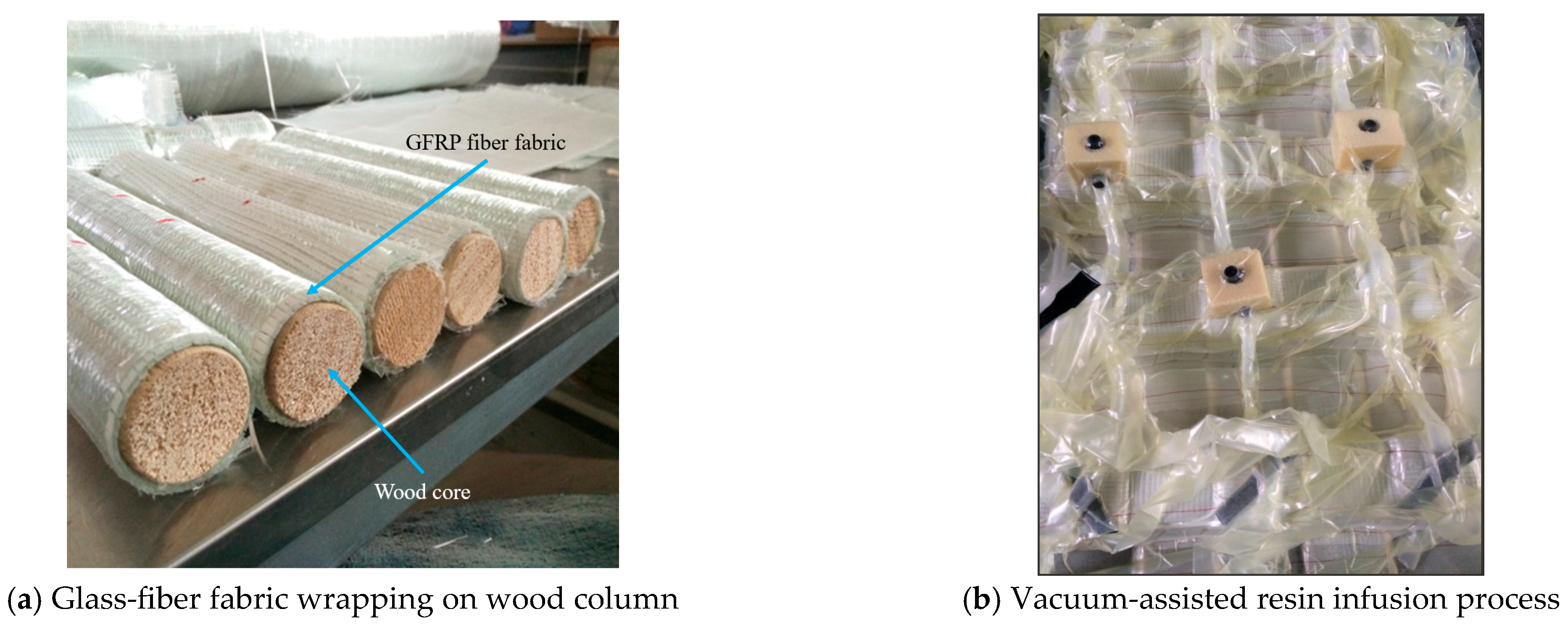
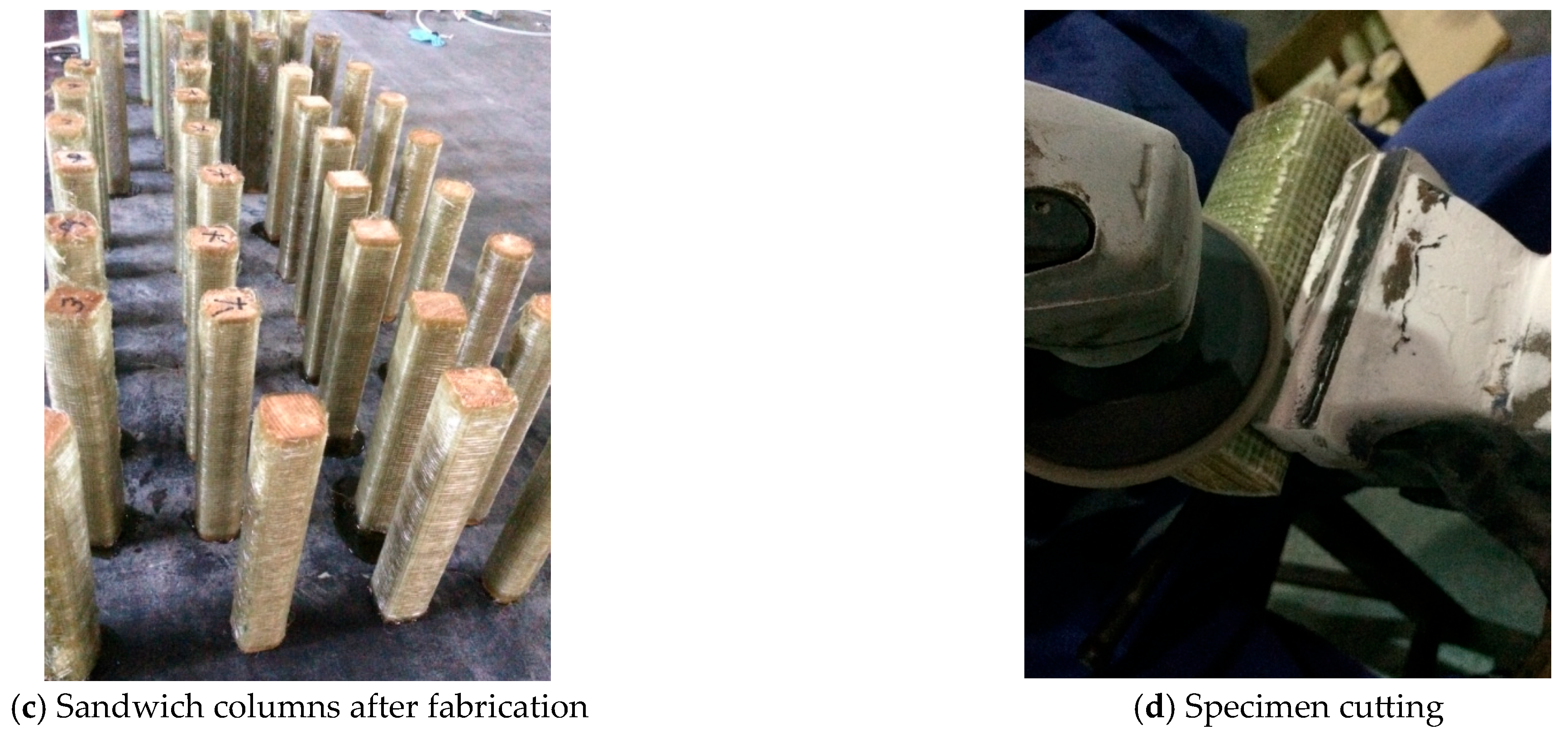
In this experiment, square and circular Paulownia wood columns with three chamfer radii were fabricated as core components of wood-cored GFRP sandwich columns, as illustrated in Figure 2. The wood columns measured 40 mm in side length and 120 mm in height, with chamfer radii of 4.76 mm, 9.52 mm, and 20 mm (circular). Cross-sectional schematics of the three chamfer configurations are detailed in Figure 3. GFRP fiber fabric with a single-layer thickness of 0.6 mm and fiber orientation angles set at 0°/90° was circumferentially wrapped around the wood columns. As a thermosetting polymer, unsaturated polyester resin (UPR) demonstrates superior interfacial bond strength and enhanced creep resistance compared to thermoplastic resins [9,10]. Consequently, UPR was selected as the bonding resin for the GFRP–wood interface in this study. A vacuum-assisted resin infusion process was subsequently employed to infuse UPR under negative pressure, achieving robust interfacial bonding between the fiber fabric and wood core (Figure 4). The wrapping layer count was varied between 0 (bare wood), 2, 3, and 4 layers. The specimens are shown in Figure 4c,d.
The specimens were categorized into four groups: unconfined specimens tested at room temperature, steel hoop end-confined specimens tested at room temperature, steel hoop end-confined specimens tested at high temperatures and steel hoop end-confined specimens subjected to thermal conditioning at 200 °C followed by cooling to ambient temperature prior to mechanical testing.
Table 1 summarizes the details of all specimens. In the table, b and h represent the side length and height of the square wood columns, respectively; r denotes the chamfer radius; L indicates the number of layers of fiber fabric; and T stands for the temperature the specimen experienced prior to cooling, with 20 representing room temperature. The specimen nomenclature adheres to the following conventions: R represents room temperature conditions, P represents post-high-temperature treatment, A represents conditions under high-temperature exposure, s denotes steel hoop end confinement, r indicates chamfer radius, T represents thermal conditioning temperature (°C), and L specifies GFRP wrapping layer count. Specifically, r5, r9, and c correspond to chamfer radii of 4.76 mm, 9.52 mm, and 20 mm (cylindrical), respectively. Two replicate specimens were tested for each experimental configuration, with the average mechanical properties adopted for subsequent analysis to ensure statistical validity.

2.2. Material Properties

The Paulownia fortunei wood utilized in this study was sourced from Shandong Province, China. As a deciduous tree of the Scrophulariaceae family, it is cultivated in sustainably managed plantations with a rotation cycle of 8–12 years. The raw material cost is 1600 CNY/m3. This rapid-growing species features low material costs and has achieved extensive application in China, primarily employed in furniture manufacturing and structural applications for eco-building projects.
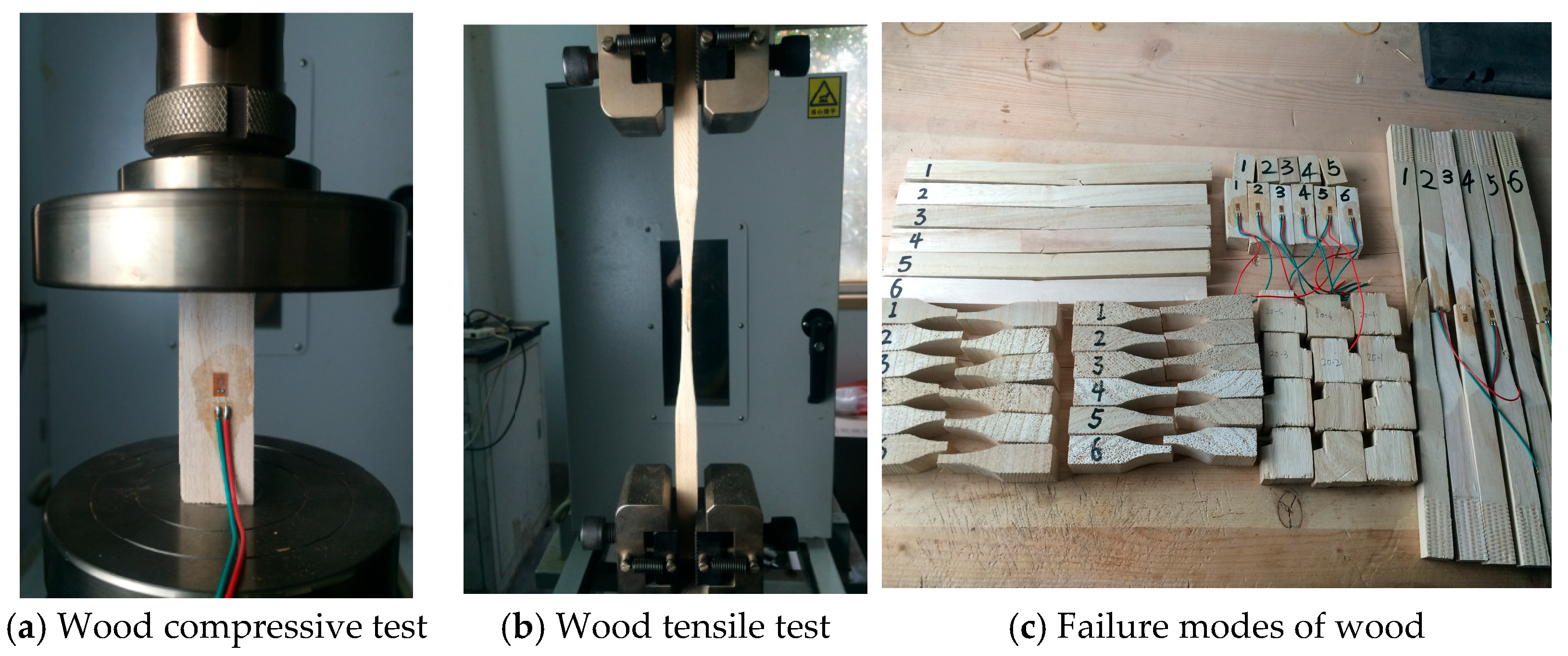
This Paulownia wood was employed as the core material for wood-cored GFRP sandwich columns in the study. The equilibrium moisture content was determined according to GB/T 1931-2009 [27]. Tensile and compressive strengths were measured following GB/T 1938-2009 [28] and GB/T 1935-2009 [29], respectively. Additionally, tangential and radial shear strengths were tested in compliance with GB/T 1937-2009 [30]. Table 2 summarizes the room-temperature properties, including density, moisture content, and mechanical strengths—specifically tensile, compressive, tangential shear, and radial shear strengths. The mechanical tests of Paulownia wood at room temperature are illustrated in Figure 5. The mechanical property data and thermal parameters of the Paulownia wood utilized in this study were sourced from the systematic experimental investigations reported by the authors [31].
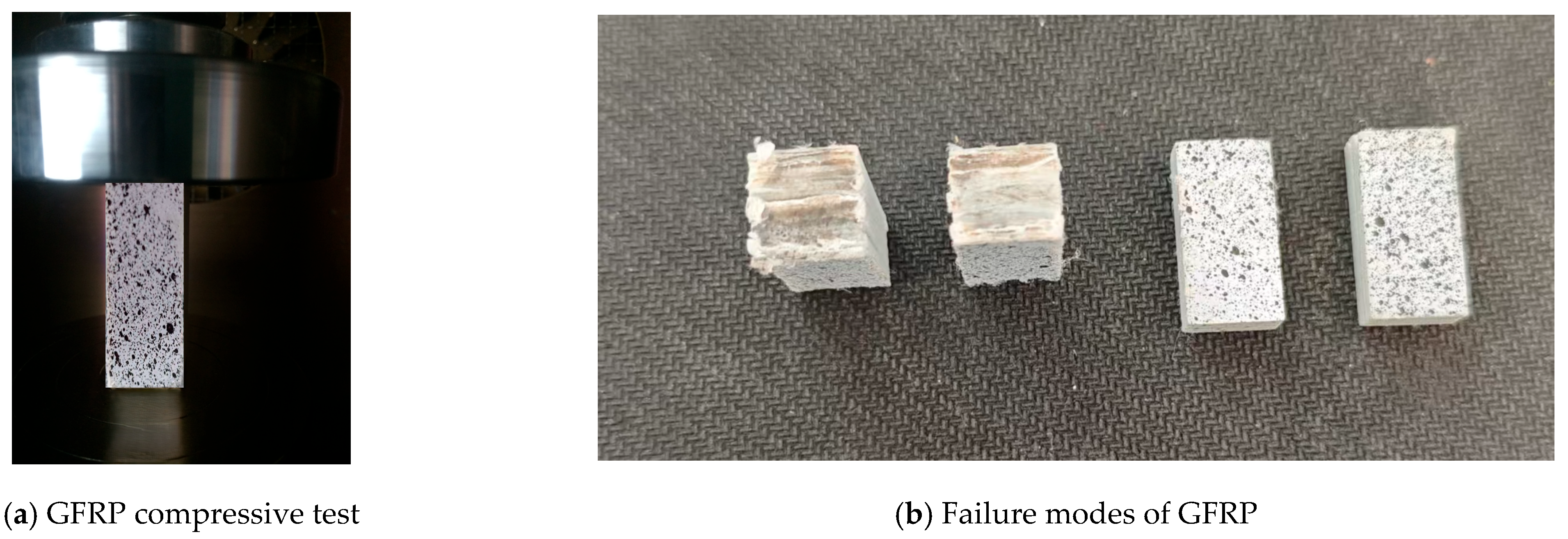
The type of fiberglass selected in the study was E-glass fiber. Tensile and compressive tests of the GFRP composites were conducted in accordance with ASTM D3039 [32] and ASTM D695 [33] standards. The mechanical tests and failure modes of the GFRP at room temperature are illustrated in Figure 6. Table 3 summarizes the mechanical properties of the composites, including tensile strength, tension Young’s modulus, compressive strength, and compression Young’s modulus, accompanied by their corresponding coefficients of variation (COV).
As for the material mechanical tests under high temperature, a thermal chamber equipped with a compression grip for uniaxial mechanical testing was utilized to heat the specimens to target temperatures. Mechanical loading was applied at a constant crosshead speed of 2 mm/min. This protocol enabled the evaluation of temperature-dependent degradation in the parallel-to-grain compressive and tensile strengths of the wood, as well as the axial compressive strength of the GFRP under elevated temperatures.

2.3. Test Instruments and Loading Protocol

Thermogravimetric analysis (TGA) and differential scanning calorimetry (DSC) experiments were conducted on the Paulownia wood and GFRP composite. NETZSCH STA409 and NETZSCH DSC200F3 manufactured by NETZSCH Scientific Instruments Trading (Shanghai) Co., Ltd. (Shanghai, China) were adopted to conduct the TGA and DSC experiments, respectively. Powder samples of GFRP and Paulownia wood were kept in a standard conditioning room (20 ± 2 °C, 75% humidity) prior to thermal testing. Tests were conducted at a heating rate of 5 °C /min, ranging from room temperature to 550 °C. Air was employed as a purge gas, with nitrogen additionally serving as a protective gas.
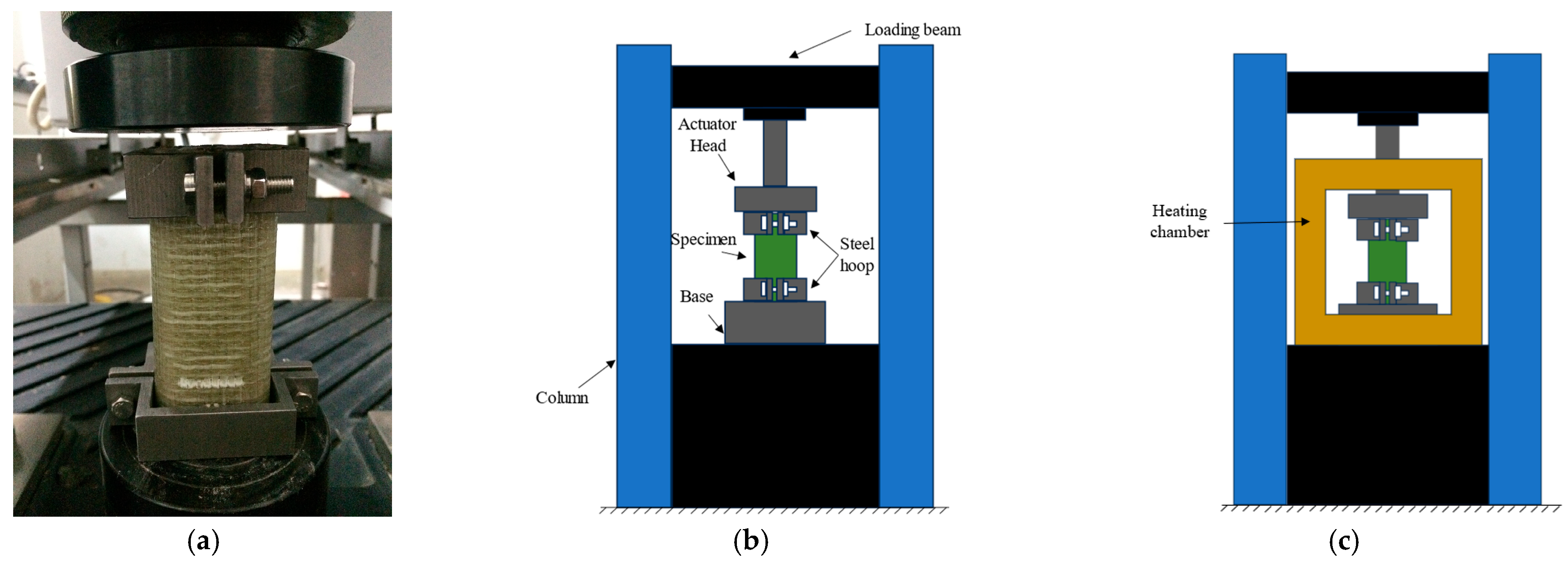
Three experimental protocols were implemented to evaluate the mechanical responses of the specimens under varying thermal histories. Specimens designated for the ambient condition were directly subjected to axial compression testing, while at-high-temperature and post-high-temperature specimens underwent controlled thermal conditioning in a programmable furnace. The thermal protocol involved heating at a rate of 5 °C/min to a target temperature of 200 °C, followed by a 60 min isothermal hold. The temperatures of the core center and the GFRP–wood interface were monitored using a reference specimen. After thermal exposure, the mechanical load was applied to the at-high-temperature specimens, while the post-high-temperature specimens were allowed to cool naturally to ambient temperature over a 24 h period prior to mechanical testing. Axial compression loading was administered using a MTS E45 universal testing machine with a capacity of 300 kN (Figure 7a,b) operating in displacement-controlled mode at a constant crosshead speed of 2 mm/min. Additionally, the schematic diagram of the axial loading of specimens under high temperatures is illustrated in Figure 7c.

3. Results and Discussion

3.1. Thermal Analysis

The Thermogravimetric analysis (TGA) and differential scanning calorimetry (DSC) curves are shown in Figure 8. The TGA curve of the wood exhibited a three-stage mass loss process. At the first stage, the mass fraction of the wood continuously decreased from 40 °C to 150 °C due to moisture evaporation. This physical process can also be captured by the DSC curve, since the endothermic peak was observed within this temperature range. At the second stage, the mass fraction of the wood reduced significantly in the temperature range of 150 °C to 305 °C. This was due to the decomposition of cellulose and hemicellulose within the wood. The DSC curve also exhibited a clear exothermic peak at 305 °C. At the third stage, the mass fraction of the wood further decreased from 305 °C to 550 °C with a thermal decomposition of hemicellulose and lignin. As for the GFRP sample, similar decomposition processes were observed except for the moisture evaporation, since there was limited water in the GFRP sample. Two significant reductions in mass fraction were found at 288 °C and 420 °C with two corresponding exothermic peaks. At 200 °C, no obvious endotherm or exotherm was observed for GFRP and wood, indicating that no significant thermal decomposition was initiated at this temperature. Therefore, this temperature was deemed appropriate for the heating treatment of wood-cored sandwich specimens, ensuring they could be used safely.

3.2. Axial Compressive Strength of Component Materials

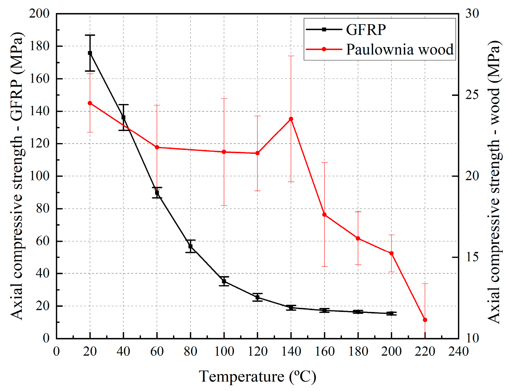
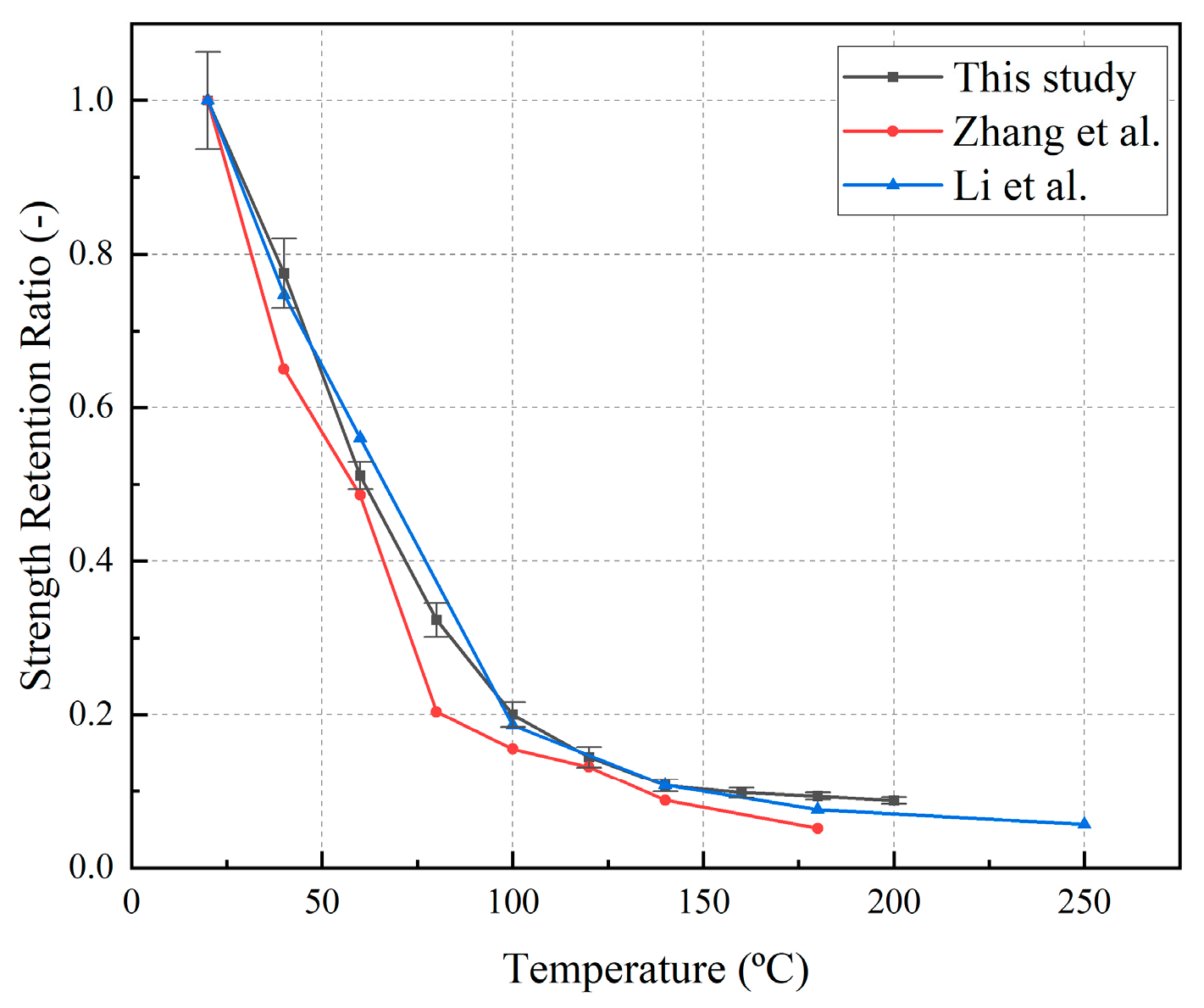
The axial compressive strength of the GFRP composites utilized in this study experienced a significant reduction at elevated temperatures, as shown in Figure 9 and Figure 10. When the temperature increased from 20 °C to 100 °C, the axial compressive strength of GFRP exhibited an almost linear reduction, reaching only 20% of its room-temperature value at 100 °C. Between 100 °C and 200 °C, the degradation trend was moderated, with the residual strength ratio dropping to as low as 8.7% at 200 °C. The residual strength-ratio-degradation behavior of the GFRP composites at elevated temperatures exhibited significant consistency with the axial compression test results documented by Zhang et al. [34] and Li et al. [35], with comparative validation presented in Figure 10. The difference may come from the fiber architectures, since the GFRP in References [34,35] were uniaxial composites. Nevertheless, the difference was very limited, since the axial compressive strength of GFRP is a matrix-dominated property. Compressive tests on Paulownia wood under elevated temperatures parallel-to-the grain were conducted by Zhang et al. [31], with the results presented in Figure 9. It can be found that the parallel-to-the grain compressive strength generally decreased from room temperature to 220 °C. Compared to GFRP, the strength of the Paulownia wood reduced slowly. At 200 °C, the axial compressive strength of the wood was very close to that of the GFRP.

3.3. Failure Modes

As shown in Figure 11a, the pure wood column R-c-20-3 exhibited end local crushing and wrinkling failure modes. This was understood, since there was no confinement at the end of this wood column. The failure mode of specimens R-r5-20-3 and R-r9-20-3 without reinforcement is shown in Figure 11b,c. As the load gradually increased, the core progressively compressed and contracted inward, while the GFRP fiber layers at the specimens’ ends were gradually crushed and peeled outward. At ultimate failure, the fiber layers at the ends were completely debonded, exhibiting a radial peeling morphology. In contrast, the specimens reinforced with steel hoops generally exhibited typical brittle fracture characteristics, as shown in Figure 12a. Failure was accompanied by a sudden explosive sound and the propagation of transverse cracks along the circumferential fiber layers and small longitudinal cracks along the axial loading direction. As for the specimens reinforced with steel hoops under high temperature, their color turned yellow, wrinkling and crushing were observed in the loading direction, and FRP rupturing was found in the circumferential direction (Figure 12b). Specimens reinforced with steel hoops maintained the same yellow color after the heating treatment, and their failure modes were similar to those at room temperature.

3.4. Load–Displacement Curve

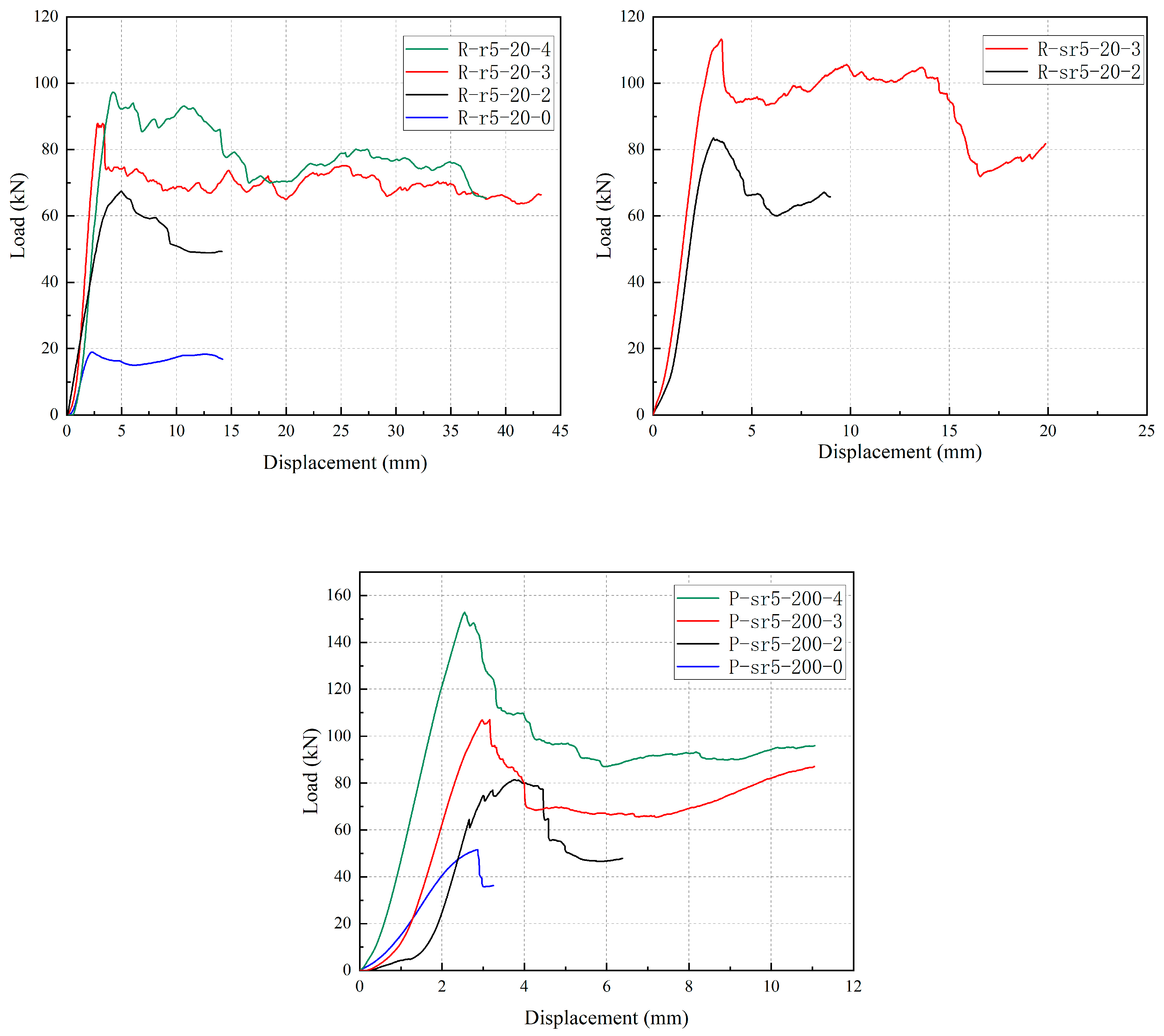
Figure 13 summarizes the representative load–displacement curves of specimens with a chamfer radius of 4.76 mm and varying numbers of fiber fabric layers. As shown in the figure, for specimens tested at room temperature, specimens cooled after high-temperature exposure, and in specimens with or without steel hoop confinement, the peak values of the load–displacement curves increased significantly with the number of fiber fabric layers. Moreover, except for specimen R-r5-20-4, the slope of the ascending segment of the load–displacement curves also increased as the number of fiber fabric layers increased. This phenomenon occurred because the circumferential confinement pressure exerted by the FRP wrap on the wood column increased with the increasing number of fiber-reinforced polymer layers. The enhanced confinement directly improved both the compressive strength and axial stiffness of the composite system [36]. Figure 14 compares the load–displacement responses of non-hooped and steel hoop-confined specimens under ambient conditions. Specimens with hoop confinement exhibited notably enhanced peak load capacity and initial stiffness compared to their non-hooped counterparts with equivalent GFRP wrapping layers. However, the steel hoop-confined specimens demonstrated accelerated post-peak load decay and a shortened residual load-bearing plateau. This behavior stemmed from the steel hoops’ dual confinement effects: a radial constraint restricts the transverse expansion of the wood core, analogous to stirrup confinement mechanisms in confined concrete, while end restraints limit transverse plastic deformation accumulation [37]. These combined effects amplified the load-carrying efficiency at the expense of reduced energy absorption capacity, ultimately promoting a more brittle failure mode characterized by abrupt interfacial fracture and suppressed ductile deformation.
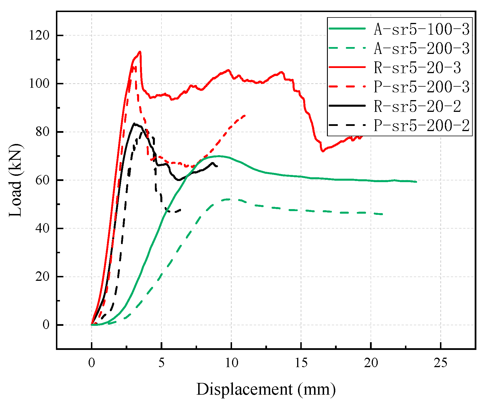
The representative load–displacement curves of specimens with steel hoop confinement under ambient (R-sr5-20-2 and R-sr5-20-3), high-temperature (A-sr5-100-3 and A-sr5-200-3) and post-high-temperature conditions (P-sr5-200-2 and P-sr5-200-3) are presented in Figure 15. The comparison shows that the peak loads of the specimens under post-high-temperature conditions are slightly lower than those tested at room temperature. This was because the temperature of 200 °C did not exceed the thermal degradation thresholds of either GFRP or wood. Consequently, the strength remained largely uncompromised after cooling to ambient temperature. Additionally, the load–displacement curves of the post-high-temperature specimens declined more rapidly after reaching the peak with a shorter residual load-bearing plateau, indicating a relatively more brittle failure. This behavior probably occurred because post-curing of the GFRP after exposure to high temperatures caused an embrittlement of the polymer matrix, characterized by reduced fracture toughness and increased susceptibility to brittle failure modes. Under high temperatures, however, both the peak load and the stiffness dropped markedly relative to the values measured at room temperature and after high-temperature exposure, with the reduction most pronounced at 200 °C.
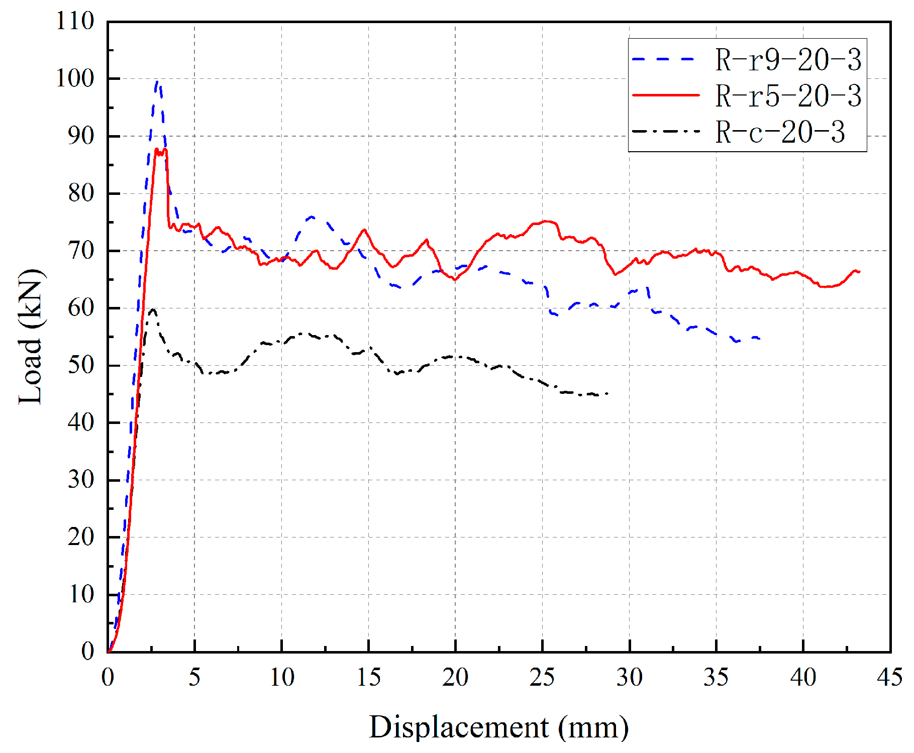
Figure 16 presents the representative load–displacement curves of specimens R-r5-20-3, R-r9-20-3, and R-c-20-3, with chamfer radii of 4.76 mm, 9.52 mm, and 20 mm, respectively, tested at room temperature. As shown in the figure, all three curves exhibited similar trends: the load increased linearly to the peak value, followed by a brief drop, and then transitioned into an extended residual load-bearing plateau, during which the displacement continued to develop while the load remained relatively stable. By comparing these three curves, it can be observed that the peak load of specimen R-r9-20-3 was slightly higher than that of R-r5-20-3, and both were significantly higher than the peak load of specimen R-c-20-3.

3.5. Energy Absorption Capacity Assessment

This section investigated the energy absorption capacity of the specimens to evaluate their impact resistance and toughness. The energy absorption capacity is defined as the energy absorbed by the specimen during deformation, which can be quantified by the area enclosed by the load–displacement curve and the coordinate axes, as shown in Equation (1) [38]:
E = 0 δ m a x F d δ
where E is the absorbed energy (J), δmax is the maximum displacement reached by the specimen before failure (mm), and F denotes the load magnitude (kN).
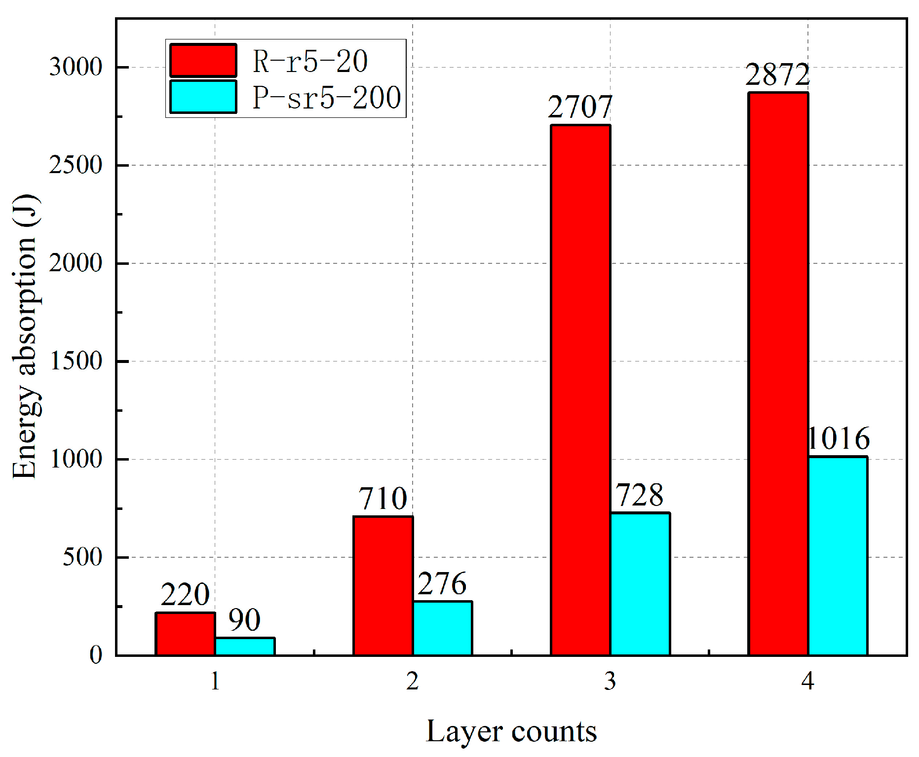
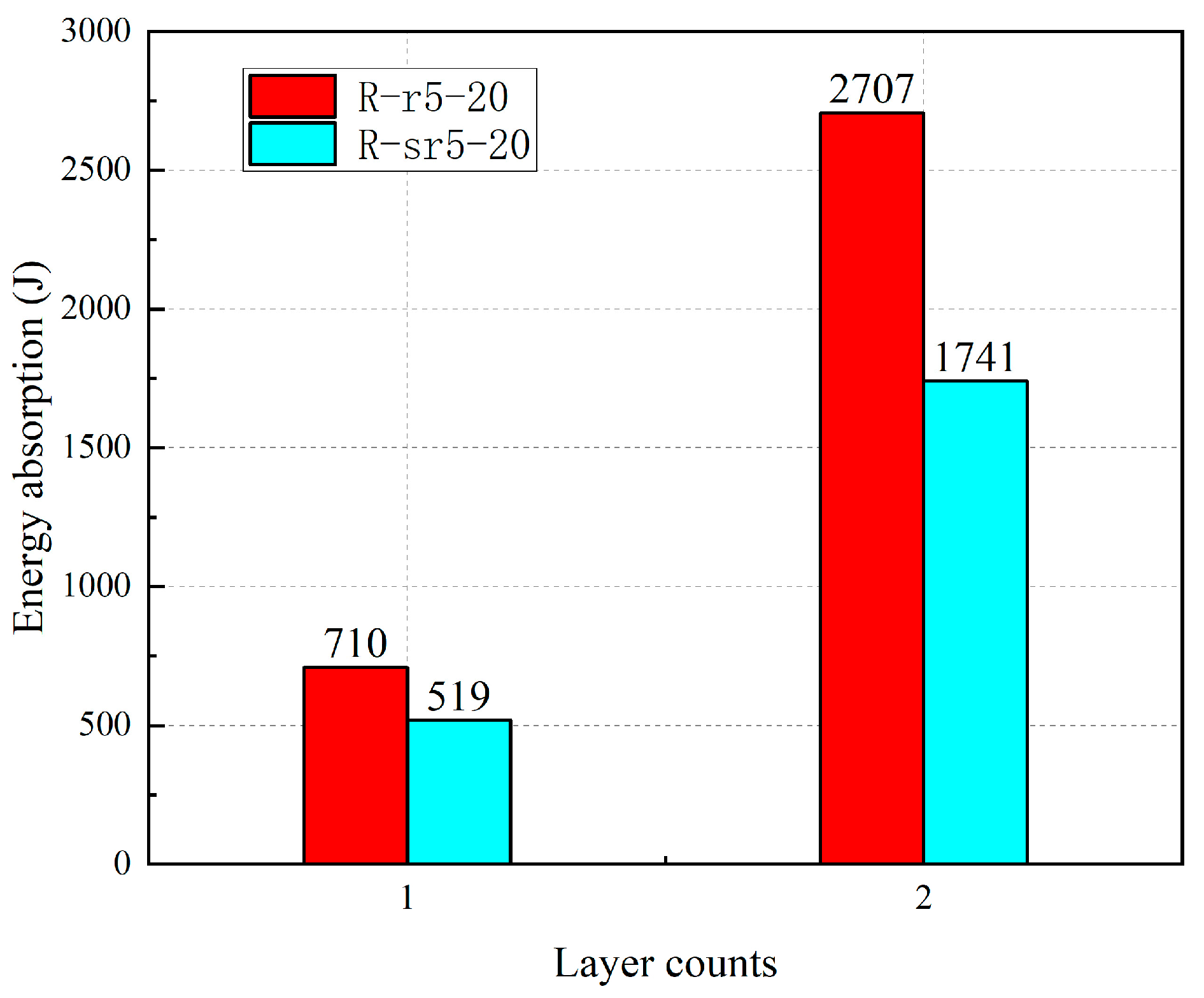
Figure 17 shows the influence of the number of GFRP layers on the energy absorption capacity for the R-r5-20 and P-sr5-200 specimen series. It can be observed that the energy absorption capacity increased significantly with the number of GFRP layers. For the P-sr5-200 specimen series, increasing the number of fiber layers from two to three resulted in a 163.77% enhancement in energy absorption. Similarly, for the R-r5-20 series, increasing the number of fiber layers from two to three led to a 280.42% increase in absorbed energy. The steel hoop confinement at the specimen ends led to a decrease in energy absorption capacity, as illustrated in Figure 18. This was attributed to the fact that while the confined specimens sustained higher loads, they exhibited inferior ductility (as discussed in Section 3.4), resulting in significantly reduced displacement before failure.
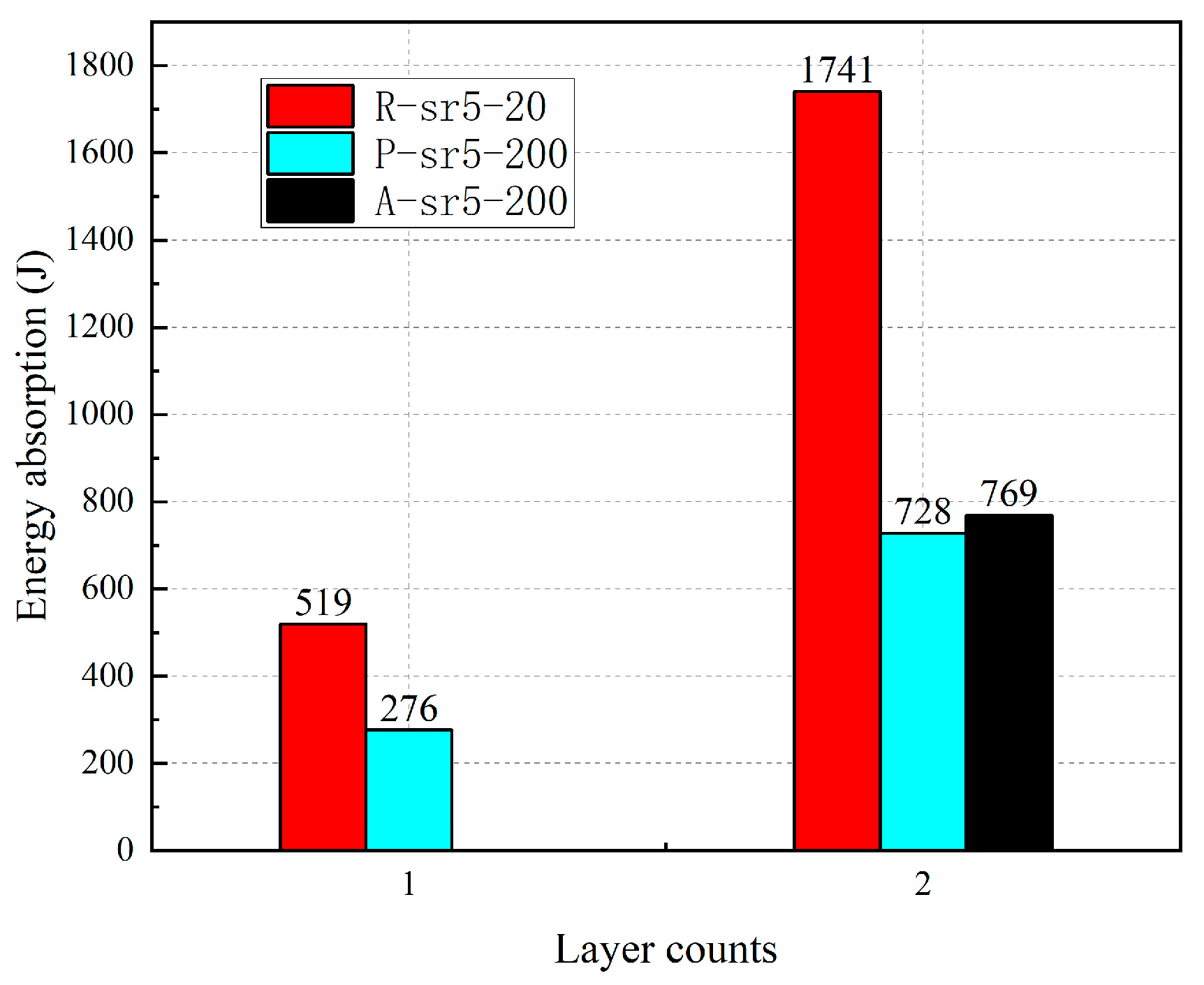
The different temperature treatments also significantly influenced the energy absorption capacity, as shown in Figure 19. The post-high-temperature specimens (P-sr5-200) exhibited markedly lower energy absorption capacity compared to the ambient-temperature specimens (R-sr5-20). Furthermore, although the specimen under high temperature (A-sr5-200-3) sustained a lower peak load than the post-high-temperature specimen (P-sr5-200-3), its superior ductility resulted in a slightly higher energy absorption capacity. The energy absorption capacity of specimens with different chamfer radii is presented in Figure 20. It can be observed that as the chamfer radius increased, the reduction in the cross-sectional area of the specimens led to a significant decrease in their energy absorption capacity. Compared to specimen R-r5-20-3, specimen R-r9-20-3 exhibited a 3.73% reduction in cross-sectional area, resulting in an 11.01% decrease in absorbed energy; meanwhile, specimen R-c-20-3 showed a 20.49% reduction in cross-sectional area, leading to a more substantial 48.10% decrease in energy absorption.

3.6. Load-Bearing Capacity and Stiffness

The load-bearing capacity of the specimen is defined as the peak load of the load–displacement curves, while the slope of the ascending segment is adopted as the stiffness. The load-bearing capacities, stiffness values, and corresponding failure modes of all specimens are summarized in Table 4.
As shown in the table, the number of fiber fabric layers has a significant impact on both the load-bearing capacity and stiffness. For the specimens at room temperature (r5-20-0, r5-20-2, r5-20-3, and r5-20-4), increasing the number of fiber layers from zero to two led to an increase of 256.12% in load-bearing capacity and 45.66% in stiffness. When the layers increased from two to three, the capacity and stiffness rose by 30.30% and 130.29%, respectively. Further increasing to four layers raised the load capacity by 10.70%, albeit with a 25.62% stiffness reduction. For the post-high-temperature specimens (sr5-200-0, sr5-200-2, sr5-200-3, and sr5-200-4), increasing the fiber layers from zero to two enhanced the load-bearing capacity and stiffness by 57.79% and 113.56%, respectively. An increase from two to three layers led to increases of 31.33% in capacity and 5.13% in stiffness. From three to four layers, the capacity and stiffness were further enhanced by 42.84% and 27.73%, respectively. Overall, the number of fiber fabric layers plays a crucial role in significantly enhancing both the load-bearing capacity and stiffness of the specimens.
By comparing the specimens without steel hoop end confinement at room temperature (r5-20-2 and r5-20-3) with those confined with steel hoops (sr5-20-2 and sr5-20-3), it can be observed that the steel hoops increased the load-bearing capacity by 23.80% and 28.89%, respectively, and improved the stiffness by 122.15% and 0.69%, respectively. These results indicate that steel hoop confinement enhances both the load-bearing capacity and stiffness of the specimens.
Through comparing the room-temperature specimens (sr5-20-2 and sr5-20-3) with the high-temperature specimens, it is observed that the load-bearing capacity of the high-temperature specimens (A-sr5-100-3 and A-sr5-200-3) decreased by 38.26% and 54.05%, respectively, while the stiffness decreased by 68.69% and 81.80%, respectively. This can be understood, since the compressive strength of the GFRP skin obviously reduced at high temperatures. Thanks to the residual compressive strength of the wood core, the specimens still exhibited considerable load-bearing capacity at 200 °C. The load-bearing capacity of the post-high-temperature specimens (P-sr5-200-2 and P-sr5-200-3) decreased by 2.46% and 5.57%, respectively, while the stiffness increased by 25.60% and 26.51%, respectively. These results indicate that the residual strength of the specimens after high-temperature exposure can be largely restored to the baseline level at room temperature, with a noticeable improvement in stiffness. It should be noted that the stiffnesses of GFRP and wood exhibited large recoveries after exposure to high temperatures below 250 °C. Moreover, similar results on the recovery in strength of GFRP and wood can be found in reference [24].
By comparing specimens with chamfer radii of 4.76 mm, 9.52 mm, and 20 mm (r5-20-3, r9-20-3, and c-20-3), it can be found that the load-bearing capacity of specimen r9-20-3 is 14.07% higher than that of r5-20-3, while r5-20-3 exhibits a 47.05% increase compared to c-20-3. This is because the specimen with a chamfer radius of 9.52 mm experienced a reduced stress concentration effect compared to that of the specimen with a 4.76 mm chamfer, resulting in a slight improvement in ultimate load-bearing capacity. In contrast, the specimen with a chamfer radius of 20 mm had a significantly smaller cross-sectional area, which lead to higher stress and earlier yielding, thereby exhibiting a much lower load-bearing capacity than the other two specimens.

4. Prediction of Axial Compressive Load-Bearing Capacity

In this study, the specimens mainly exhibited two failure modes: end crushing and mid-height fracture of the GFRP composites. For the end crushing mode, it was assumed that the axial compressive stresses on both the GFRP and the wood reached their ultimate compressive load-bearing capacity. Consequently, the specimen’s ultimate load-bearing capacity was calculated by the summation of the ultimate compressive load-bearing capacities of the fiber fabric layer and wood, respectively. For the mid-height fracture mode, the GFRP confinement must be considered. Several models have been developed for FRP-confined sandwich columns in existing studies [17,39]. Generally, the axial compressive load-bearing capacity can be calculated by considering the contributions of the GFRP and the wood. The compressive load-bearing capacity of the wood core should adopt a confined (enhanced) strength due to its confinement in the GFRP composite skin. Referencing Zhou et al. [17], this study proposed an enhancement factor λ (Equation (6)) for the parallel-to-grain compressive strength of confined wood to quantify the enhancement in axial compressive load-bearing capacity by the GFRP composite skin. Moreover, by adopting the strengths at (after) high temperatures, a predictive model for the axial compressive load-bearing capacity of the specimens in this study was developed, as detailed below.
The ultimate compressive load-bearing capacity of the specimens can be calculated by Equation (2):
N u = N w + N f
where Nu represents the predicted ultimate compressive load-bearing capacity, which is composed of Nw and Nf. The Nw and Nf denote the compressive load-bearing capacity contributions from the wood column and GFRP fiber layers, respectively. Nf can be expressed as Equation (3):
N f = σ f , c , T A f ,   a t   h i g h   t e m p e r a t u r e k σ f , c , 20 A f r p ,   p o s t   h i g h   t e m p e r a t u r e
where σf,c,T represents the compressive strength of GFRP at temperature T; σf,c,20 denotes the compressive strength of GFRP at room temperature; k represents the tensile and compressive strength retention ratio of GFRP after high-temperature exposure relative to its room-temperature strength properties, with a value of 0.9 adopted in this study. Af is the load-bearing area of GFRP fiber layers, which can be calculated as Equation (4):
A f = L t f P
where L denotes the number of layers of GFRP fiber fabric; tf denotes a single-layer fiber thickness (0.6 mm) and P denotes the perimeter of the specimen’s cross-section. The compressive load-bearing capacity contributions from wood column Nw from Equation (2) can be calculated as Equations (5)–(7):
N w = σ w , 0 , T A w ,   n o n     c o n f i n e d λ σ w , 0 , T A w ,   s t e e l   h o o p     c o n f i n e d  
where σw,0,T represents the parallel-to-grain compressive strength of the wood at temperature T and Aw denotes the cross-sectional area of the wood column. The coefficient λ represents the enhancement factor for the parallel to grain compressive strength of confined wood, which can be defined as Equation (6):
λ = a + b f l σ w , 90 , T
where coefficients a and b are regression-derived parameters, assigned values of 0.4239 and 0.1302, respectively; σw,90,T represents the perpendicular-to-grain compressive strength of the wood at temperature T. fl denotes the lateral confining stress provided by the GFRP wraps, which can be expressed as Equation (7):
f l = 2 σ f , t , T t f L b ,   a t   h i g h   t e m p e r a t u r e 2 k σ f , t , 20 t f L b ,   p o s t   h i g h   t e m p e r a t u r e
where σf,t,T and σf,t,20 denote the tensile strength of GFRP at temperature T and room temperature, respectively, and b denotes the width dimension of the wood column cross-section. All aforementioned parameters can be located in Table 1, Table 2, Table 3 and Table 5, as well as Figure 9.
The predicted axial compressive load-bearing capacities of the wood-cored GFRP sandwich specimens are summarized in Table 4. By comparing the predicted and experimental axial compressive load-bearing capacity values, it can be found that the predicted values agreed well with the experimental values, with a maximum deviation of 17% and a mean (predicted value to experimental value) ratio of 1.01. Hence, the developed model can accurately predict the axial compressive load-bearing capacity of wood-cored GFRP sandwich specimens, accounting for the lateral confinement, GFRP layers, and the high-temperature conditions.

5. Conclusions

This study systematically investigated the axial compressive mechanical performance of wood-cored GFRP sandwich columns, revealing the effects of the number of GFRP wrapping layers, steel hoop end confinement, high-temperature treatment, and chamfer radius on the axial compressive performance. The conclusions are summarized as follows:
  • The wood-cored GFRP sandwich wood columns markedly enhanced the axial compressive performance of the bare wood. The number of GFRP wrapping layers significantly contributed to the improvement of load-bearing capacity and stiffness. At room temperature, increasing the number of fiber layers from zero to four resulted in an increase of 413.67% in load-bearing capacity and 153.04% in stiffness, respectively.
  • When the temperature was elevated from room temperature to 100 °C and 200 °C, the load-bearing capacity declined by 38.26% and 54.05%, respectively. Upon cooling back to room temperature, the specimens recovered roughly 95% of their original strength, indicating that the observed losses were primarily thermo-elastic and that thermal decomposition had not yet been initiated.
  • Introducing a 9.52 mm chamfer radius effectively mitigated stress concentrations and elevated the load-bearing capacity by 14.07% relative to a 4.76 mm radius. However, enlarging the radius to 20 mm caused a marked decline in capacity, as the pronounced reduction in cross-sectional area outweighed the benefits of further stress relief.
  • The number of GFRP layers exhibited a positive correlation with energy absorption capacity. For the P-sr5-200 specimen series, increasing the number of fiber layers from two to three resulted in a 163.77% enhancement in energy absorption. Conversely, steel hoop confinement reduced energy absorption due to its adverse effect on ductility. Post-high-temperature specimens demonstrated significantly lower energy absorption capacity than those under ambient temperature conditions, while the specimen under high temperature conditions exhibited marginally higher energy absorption than the post-high-temperature specimen due to its superior ductility. Furthermore, an increase in chamfer radius diminished the cross-sectional area, resulting in reduced energy absorption capacity.
  • End crushing was observed in the specimens without lateral confinement, whereas mid-height fracture occurred in those with confinement. The GFRP skin provided effective lateral confinement in conjunction with the steel hoops. Drawing on these two distinct failure modes, a predictive model for the axial compressive load-bearing capacity was established. The calculated capacities showed excellent agreement with the experimental results for the wood-cored GFRP sandwich columns.
  • This study assessed the axial performance of small-scale wood-cored GFRP sandwich columns. To quantify the size effect, future research will extend the investigation to full-scale specimens.

Author Contributions

Methodology, L.Z.; Formal analysis, Y.F.; Investigation, Y.K. and W.P.; Resources, Z.X.; Writing—original draft, Y.K. and Y.F.; Writing—review and editing, Y.K., Y.F., Z.X., W.P., Z.C. and L.Z.; Supervision, L.Z.; Software, Z.C. All authors have read and agreed to the published version of the manuscript.

Funding

This research was funded by [Qinglan Project (Yangzhou University)] (Grant No. 137050635).

Data Availability Statement

The original contributions presented in this study are included in the article. Further inquiries can be directed to the corresponding author.

Conflicts of Interest

The authors declare no conflicts of interest.

References

  1. Hildebrandt, J.; Hagemann, N.; Thrän, D. The contribution of wood-based construction materials for leveraging a low carbon building sector in europe. Sustain. Cities Soc. 2017, 34, 405–418. [Google Scholar] [CrossRef]
  2. Qu, M.; Pelkonen, P.; Tahvanainen, L.; Arevalo, J.; Gritten, D. Experts’ assessment of the development of wood framed houses in China. J. Clean. Prod. 2012, 31, 100–105. [Google Scholar] [CrossRef]
  3. Ximenes, F.A.; Grant, T. Quantifying the greenhouse benefits of the use of wood products in two popular house designs in Sydney, Australia. Int. J. Life Cycle Assess. 2012, 18, 891–908. [Google Scholar] [CrossRef]
  4. Hu, A.-n.; Ren, H.-t.; Yao, Q.-f. Durability of concrete structures strengthened with FRP laminates. J. Harbin Inst. Technol. 2007, 14, 571–576. [Google Scholar]
  5. Pu, Z.; Wang, Z.; Guan, T.; Tao, X.; Liu, Y.; Yang, Z.; Wang, H.; Sheikh, S.A. Shear Performance of the GFRP Bolt Interface Between the GFRP Profile and UHPC/Concrete Slabs. Struct. Des. Tall Spéc. Build. 2025, 34, e70019. [Google Scholar] [CrossRef]
  6. Rossini, M.; Balconi, G.; Zoller, A.; Braghiroli, N.; Poggi, C.; Nanni, A. Thermoplastic GFRP for Reinforced and Prestressed Concrete. Lect. Notes Civ. Eng. 2023, 351, 140–156. [Google Scholar]
  7. Hurynovich, V.; Nanni, A. GFRP Reinforcement for Concrete Facilities to Protect Against Mudflow. Concr. Int. 2024, 46, 38–42. [Google Scholar]
  8. Zhang, Z.; Ji, Q.; Guo, Z.; Li, C.; Guo, R.; Tian, J.; Zhang, Z.; He, T.; Xian, G. Design, preparation, and mechanical properties of glass fiber reinforced thermoplastic self-anchor plate cable exposed in alkaline solution environment. Polym. Compos. 2024, 45, 11687–11700. [Google Scholar] [CrossRef]
  9. Du, H.; Xian, G.; Tian, J.; Ma, Z.; Li, C.; Xin, M.; Zhang, Y. Effect of fiber surface treatment with silane coupling agents and carbon nanotubes on mechanical properties of carbon fiber reinforced polyamide 6 composites. Polym. Compos. 2024, 46, 1267–1283. [Google Scholar] [CrossRef]
  10. Pan, Y.; Chang, B.; Lu, Z.; Su, L.; Zhu, J. Effects of seawater on durability of hybrid C/BFRP-confined seawater–sea sand concrete columns under axial compression. Adv. Struct. Eng. 2023, 26, 2879–2893. [Google Scholar] [CrossRef]
  11. Zhang, F.; Xie, S.; Xiao, J.; Singh, A.; Xu, J.; Fang, H. Mechanical behavior of Glass fiber-reinforced polymer-timber-steel tube-concrete composite columns under axial compression. Struct. Concr. 2022, 24, 1296–1312. [Google Scholar] [CrossRef]
  12. Mathuros, A.; Thongchom, C.; Bui, L.V.H.; Jongvivatsakul, P. Monotonic and cyclic flexural performance of timber beams strengthened with glass fiber-reinforced polymer rods using near-surface mounted technique. Structures 2024, 65, 106729. [Google Scholar] [CrossRef]
  13. Yang, L.; Li, X.; Fang, H.; Liu, W.; Hong, J.; Hui, D.; Gaff, M. Compressive behaviour of wood-filled GFRP square columns with lattice-web reinforcements. Constr. Build. Mater. 2021, 310, 125129. [Google Scholar] [CrossRef]
  14. Osei-Antwi, M.; de Castro, J.; Vassilopoulos, A.P.; Keller, T. FRP-Balsa Composite Sandwich Bridge Deck with Complex Core Assembly. J. Compos. Constr. 2013, 17, 04013011. [Google Scholar] [CrossRef]
  15. Zhang, L.; Liu, W.; Wang, L.; Ling, Z. Mechanical behavior and damage monitoring of pultruded wood-cored GFRP sandwich components. Compos. Struct. 2019, 215, 502–520. [Google Scholar] [CrossRef]
  16. Wang, L.; Liu, W.; Hui, D. Compression strength of hollow sandwich columns with GFRP skins and a paulownia wood core. Compos. Part B Eng. 2014, 60, 495–506. [Google Scholar] [CrossRef]
  17. Zhou, C.; Liang, L.; Siha, A.; Zhang, I.; Yang, L. Compressive Stress-Strain Model of Combined Strengthening Rectangular Timber Columns. J. Build. Mater. 2021, 24, 171–180. [Google Scholar] [CrossRef]
  18. Tsoi, M.; Zhuge, J.; Chen, R.-H.; Gou, J. Modeling and experimental studies of thermal degradation of glass fiber reinforced polymer composites. Fire Mater. 2013, 38, 247–263. [Google Scholar] [CrossRef]
  19. Correia, J.R.; Bai, Y.; Keller, T. A review of the fire behaviour of pultruded GFRP structural profiles for civil engineering applications. Compos. Struct. 2015, 127, 267–287. [Google Scholar] [CrossRef]
  20. Alhayek, A.; Syamsir, A.; Supian, A.B.M.; Usman, F. Lifespan prediction of glass fiber reinforced polymers subjected to flexural creep and elevated temperatures using analytical and numerical analyses. Polym. Compos. 2024, 45, 17166–17185. [Google Scholar] [CrossRef]
  21. Li, C.; Xian, G. Mechanical property evolution and life prediction of carbon fiber and pultruded carbon fiber reinforced polymer plate exposed to elevated temperatures. Polym. Compos. 2020, 41, 5143–5155. [Google Scholar] [CrossRef]
  22. Yu, Y.; Liu, S.; Pan, Y.; Miu, X.; Liu, J. Durability of glass fiber-reinforced polymer bars in water and simulated concrete pore solution. Constr. Build. Mater. 2021, 299, 123995. [Google Scholar] [CrossRef]
  23. Zhang, L.; Chen, K.; Liu, W.; Liu, Y.; Wang, K.; Ge, W.; Guo, K. Fire performance of pultruded wood-cored GFRP sandwich components for building construction. Case Stud. Constr. Mater. 2022, 17, e01555. [Google Scholar] [CrossRef]
  24. Lotfalipour, F.; Javid, A.; Toufigh, V. Boosting algorithms for predicting the bond properties of timber and fiber reinforced polymer (FRP) under thermal cycling using single-lap shear tests. Eur. J. Wood Wood Prod. 2025, 83, 1–22. [Google Scholar] [CrossRef]
  25. Wang, L.; Fan, X.; Chen, H.; Liu, W. Axial crush behavior and energy absorption capability of foam-filled GFRP tubes under elevated and high temperatures. Compos. Struct. 2016, 149, 339–350. [Google Scholar] [CrossRef]
  26. Zhang, L.; Liu, W.; Omar, A.A.; Ling, Z.; Yang, D.; Liu, Y. Postfire performance of pultruded wood-cored GFRP sandwich beams. Thin-Walled Struct. 2023, 193, 111240. [Google Scholar] [CrossRef]
  27. GB/T 1931-2009; Method for Determination of Moisture Content of Wood. China Standard Press: Beijing, China, 2009.
  28. GB/T 1938-2009; Method of Testing in Tensile Strength Paralle to Grain of Wood. China Standard Press: Beijing, China, 2009.
  29. GB/T 1935-2009; Method of Testing in Compressive Strength Paralle to Grain of Wood. China Standard Press: Beijing, China, 2009.
  30. GB/T 1937-2009; Method of Testing in Shearing Strength Paralle to Grain of Wood. China Standard Press: Beijing, China, 2009.
  31. Zhang, L.; Chen, K.; Xu, B.; Liu, Y.; Guo, K. Parallel-to-Grain Compressive and Tensile Behavior of Paulownia Wood at Elevated Temperatures. Appl. Sci. 2022, 12, 12118. [Google Scholar] [CrossRef]
  32. ASTM D3039/D3039M-17; Standard Test Method for Tensile Properties of Polymer Matrix Composite Materials. ASTM: West Conshohocken, PA, USA, 2017.
  33. ASTM D3410/D3410M-16(2024); Standard Test Method for Compressive Properties of Polymer Matrix Composite Materials with Unsupported Gage Section by Shear Loading. ASTM: West Conshohocken, PA, USA, 2024.
  34. Zhang, L.; Liu, W.; Wang, L.; Ling, Z. On-axis and off-axis compressive behavior of pultruded GFRP composites at elevated temperatures. Compos. Struct. 2020, 236, 111891. [Google Scholar] [CrossRef]
  35. Li, Q. Study on Web Crippling Behavior of GFRP Pultruded Profiles under Elevated Temperature. Master’s Thesis, Yangzhou University, Yangzhou, China, 2024. [Google Scholar]
  36. Wang, L.; Shi, F.; Zhao, M.; Wang, B.J.; Li, H.; Zou, X.; Du, H. Axial compressive behavior of FRP-confined laminated timber columns. Arch. Civ. Mech. Eng. 2023, 24, 28. [Google Scholar] [CrossRef]
  37. Xie, J.; Yang, L.; Xu, F.Q. Study on axial compression performance of concrete stub column strengthened by prestressed steel hoop. Gongcheng Lixue Eng. Mech. 2020, 37, 195–208. [Google Scholar]
  38. Wang, L.; Liu, W.; Fang, Y.; Wan, L.; Huo, R. Axial crush behavior and energy absorption capability of foam-filled GFRP tubes manufactured through vacuum assisted resin infusion process. Thin-Walled Struct. 2016, 98, 263–273. [Google Scholar] [CrossRef]
  39. Teng, J.G.; Lam, L. Behavior and Modeling of Fiber Reinforced Polymer-Confined Concrete. J. Struct. Eng. 2004, 130, 1713–1723. [Google Scholar] [CrossRef]
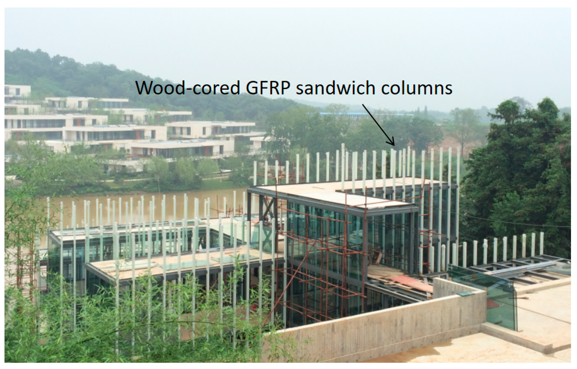
Figure 1. A tourism building, “Jade bamboo”, under construction using wood-cored GFRP sandwich columns in 2016.
Buildings 15 03632 g001
Figure 2. Paulownia wood core columns.
Buildings 15 03632 g002
Figure 3. Cross-sectional schematics of the three chamfer configurations.
Buildings 15 03632 g003
Figure 4. Vacuum-assisted wrapping process of GFRP fiber fabric on wood columns.
Buildings 15 03632 g004aBuildings 15 03632 g004b
Figure 5. Mechanical tests and failure modes of Paulownia wood at room temperature.
Buildings 15 03632 g005
Figure 6. Mechanical tests and failure modes of GFRP at room temperature.
Buildings 15 03632 g006
Figure 7. Axial loading apparatus and schematic diagrams. (a) Axial loading apparatus; (b) Schematic diagram of loading on post-high-temperature and ambient-condition specimens; (c) Schematic diagram of axial loading on specimens at high temperatures.
Buildings 15 03632 g007
Figure 8. TGA and DSC test results of the Paulownia wood and GFRP (Td,onset denotes the temperature at the onset of decomposition, Td refers to the temperature at which the maximum decomposition rate occurred, Td,end indicates the temperatures at the conclusion of thermal decomposition; the subscripts w and FRP represent Paulownia wood and GFRP, respectively).
Buildings 15 03632 g008
Figure 9. Axial (parallel-to-grain) compressive strength of GFRP composites and Paulownia wood at high temperatures.
Buildings 15 03632 g009
Figure 10. Reduction in compressive strength of GFRP at elevated temperatures [34,35].
Buildings 15 03632 g010
Figure 11. Failure modes of non-hooped specimens at room temperature.
Buildings 15 03632 g011
Figure 12. Failure modes of hoop-confined specimens.
Buildings 15 03632 g012
Figure 13. Representative load–displacement curves of specimens with varying GFRP layer counts and a chamfer radius of 4.76 mm.
Buildings 15 03632 g013
Figure 14. Representative load–displacement curves of hoop-confined and non-hooped specimens under ambient temperature.
Buildings 15 03632 g014
Figure 15. Representative load–displacement curves of hoop-confined specimens under ambient, high-temperature, and post-high-temperature conditions.
Buildings 15 03632 g015
Figure 16. Representative load–displacement curves of three-layer GFRP-wrapped specimens with chamfer radii of 4.76 mm, 9.52 mm, and 20 mm under ambient temperature.
Buildings 15 03632 g016
Figure 17. Comparison of energy absorption capacity in specimens with different numbers of GFRP layers.
Buildings 15 03632 g017
Figure 18. Comparison of energy absorption capacity between specimens with and without steel hoop reinforcement.
Buildings 15 03632 g018
Figure 19. Comparison of energy absorption capacity between specimens subjected to different temperature treatments.
Buildings 15 03632 g019
Figure 20. Comparison of energy absorption capacity between specimens with different chamfer radii.
Buildings 15 03632 g020
Table 1. Specimen information.
Specimenb (mm)h (mm)r (mm)L (Layer Count)T (°C)Heating Treatment
R-r5-20-0401204.76020No
R-r5-20-2401204.76220No
R-r5-20-3401204.76320No
R-r5-20-4401204.76420No
R-sr5-20-2401204.76220No
R-sr5-20-3401204.76320No
R-r9-20-3401209.52320No
R-c-20-34012020320No
A-sr5-100-3401204.763100At high temperature
A-sr5-200-3401204.763200At high temperature
P-sr5-200-2401204.762200Post high temperature
P-sr5-200-3401204.763200Post high temperature
P-sr5-200-4401204.764200Post high temperature
Table 2. Mechanical properties of Paulownia wood at room temperature.
Density (kg/m3)Moisture Content (%)Parallel-to-Grain Tensile StrengthParallel-to-Grain Compressive StrengthTangential ShearRadial Shear StrengthPerpendicular-to-Grain Tensile StrengthPerpendicular-to-Grain Compressive Strength
(MPa)COV(MPa)COV(MPa)COV(MPa)COV(MPa)COV(MPa)COV
35310.943.60.14324.50.0676.60.0904.50.0912.50.1172.70.129
Table 3. Material properties of GFRP at room temperature.
Tensile StrengthTensile ModulusCompressive StrengthCompressive Modulus
(MPa)COV(GPa)COV(MPa)COV(GPa)COV
297.60.01523.50.011175.80.02822.10.031
Table 4. Summary of ultimate load capacity, stiffness, and failure modes.
SpecimenPu (kN)K (kN/mm)Failure ModesNu (kN)Nu/Pu
R-r5-20-018.9413.14End crushing--
R-r5-20-267.4519.41End crushing70.761.05
R-r5-20-387.8944.70End crushing86.770.99
R-r5-20-497.2933.25End crushing102.791.06
R-sr5-20-283.5043.12Mid-height fiber fracture81.850.98
R-sr5-20-3113.2845.01Mid-height fiber fracture114.571.01
R-r9-20-3100.2645.59End crushing82.760.83
R-c-20-359.7736.43End crushing70.561.18
A-sr5-100-369.9314.09Mid-height fiber fracture68.10.97
A-sr5-200-352.058.19Mid-height fiber fracture54.71.05
P-sr5-200-281.4554.16Mid-height fiber fracture79.350.97
P-sr5-200-3106.9756.94Mid-height fiber fracture113.931.07
P-sr5-200-4152.8072.73Mid-height fiber fracture148.510.97
Mean 1.01
Table 5. Information regarding the relevant parameters in the equations.
SpecimenAw (mm2)P (mm)σf,c,T (MPa)σf,t,T (MPa)σw,0,T (MPa)σw,90,T (MPa)
R-r5-20-01580.6151.8--24.52.7
R-r5-20-21580.6151.8175.8297.624.52.7
R-r5-20-31580.6151.8175.8297.624.52.7
R-r5-20-41580.6151.8175.8297.624.52.7
R-sr5-20-21580.6151.8175.8297.624.52.7
R-sr5-20-31580.6151.8175.8297.624.52.7
R-r9-20-31522.2143.7175.8297.624.52.7
R-c-20-31256.6125.7175.8297.624.52.7
A-sr5-100-31580.6151.835.2238.121.52.2
A-sr5-200-31580.6151.815.4178.615.21.2
P-sr5-200-21580.6151.8--15.21.2
P-sr5-200-31580.6151.8--15.21.2
P-sr5-200-41580.6151.8--15.21.2
Disclaimer/Publisher’s Note: The statements, opinions and data contained in all publications are solely those of the individual author(s) and contributor(s) and not of MDPI and/or the editor(s). MDPI and/or the editor(s) disclaim responsibility for any injury to people or property resulting from any ideas, methods, instructions or products referred to in the content.