Abstract
Global urbanization has led to massive generation of high-water-content waste slurry, creating serious environmental challenges. Conventional treatment methods are costly and unsustainable, while cement-based foamed lightweight soils typically exhibit low strength and limited CO2 sequestration. To address this issue, this study proposes a novel stabilization pathway by integrating a MgO–mineral powder–carbide slag composite binder with CO2 foaming–carbonation. The approach enables simultaneous slurry lightweighting, strength enhancement, and CO2 fixation. A series of laboratory tests were conducted to evaluate flowability, density, compressive strength, and deformation characteristics of the carbonated lightweight stabilized slurry. Microstructural analyses, including SEM and XRD, were used to reveal the formation of carbonate phases and pore structures. The results showed that MgO content strongly promoted carbonation, leading to denser microstructures and higher strength, while mineral powder and carbide slag optimized workability and pore stability. Orthogonal testing indicated that a mix with 25% mineral powder, 12.5% MgO, and 7.5% carbide slag achieved the best performance, with unconfined compressive strength up to 0.48 MPa after carbonation. Compared with conventional cement- or GGBS-based foamed lightweight soils, the proposed system exhibits superior strength development, improved pore stability, and enhanced CO2 sequestration potential. These findings demonstrate the feasibility of recycling high-water-content waste slurry into value-added construction materials while contributing to carbon reduction targets. This study not only provides a sustainable solution for waste slurry management but also offers new insights into the integration of CO2 mineralization into geotechnical engineering practice.
1. Introduction
With urbanization and the growing emphasis on environmental protection, global warming caused by the greenhouse effect has gained increasing attention. Consequently, reducing and managing CO2, the primary greenhouse gas, has become a key environmental issue. Research indicates that capturing and storing emitted CO2 is the most direct and effective method for reducing atmospheric CO2 concentrations. The primary approaches for controlling total CO2 emissions include enhancing CO2 utilization, reducing emissions at the source, geological storage, ocean storage, and mineral carbonation [1]. In the field of civil engineering, the application of carbon sequestration technology offers new perspectives for the development of “green civil engineering.”
With the accelerated pace of urbanization, the amount of waste slurry generated from construction activities continues to increase. The 2024 Special Research and In-Depth Analysis Report on China’s Construction Waste Treatment Industry [2] indicates that China’s annual construction waste production has reached the scale of 1 billion tons, while its resource utilization rate remains low. Without proper treatment, this waste could lead to secondary environmental issues such as water and soil contamination. Additionally, due to limited urban land and high population density, waste slurry disposal has become an urgent issue.
To address these issues, civil engineering researchers have developed carbonation-stabilized lightweight soil to facilitate waste slurry recycling. This material not only absorbs CO2 but also efficiently utilizes construction waste. Converting construction waste into new building materials reduces soil accumulation and minimizes the risk of secondary pollution during disposal. Construction waste can react with carbon capture materials to form stable carbon sequestration products, effectively managing waste while achieving carbon storage. Currently, research in this field primarily focuses on the development of waste slurry recycling technologies and magnesium oxide-based carbon sequestration techniques.
To address the issue of waste slurry recycling, He et al. [3] conducted a study on marine clay and found that the addition of polyacrylamide (PAM) promotes the formation of large-flake flocs in waste slurry, effectively improving its performance and enabling rapid solid–liquid separation. Yadu [4] found through unconfined compressive strength tests that granulated blast furnace slag (GGBS) significantly improves the strength of soft soil, although excessive amounts of mineral powder have limited effect on strength improvement. Singhi [5] incorporated a mixture of slag and fly ash into soft soil for soil improvement, and the study showed that the strength of the stabilized soil increased significantly with higher amounts of composite stabilizers. However, traditional stabilizers cause significant environmental pollution, making the search for stabilizers that balance performance and environmental friendliness one of the key research focuses in this field.
Recent work from 2022 to 2024 has significantly advanced CO2 mineralization and carbonation-based stabilization in geotechnical engineering. Wang et al. [6] prepared low-carbon foamed lightweight soil using cement, GBFS, and fly ash, achieving 28-day unconfined compressive strength values of 1.9 MPa at 600 kg/m3 density while reducing CO2 emissions by up to 70% compared with pure cement systems. Investigations into accelerated carbonation of alkali-activated slag stabilized sandy soil confirmed that carbonation promotes carbonate formation and strength gains under both ambient and elevated curing conditions [7]. Ngo et al. [8] proposed a sol–gel stabilized CO2 foam to enhance in situ carbonation in foamed fly ash backfills, demonstrating improved strength and microstructure. Que et al. [9] showed that marine sand-amended FLS can achieve unconfined compressive strength values of 0.95–2.64 MPa with flowability between 160 and 229 mm, underscoring the versatility of FLS in sustainable design. Furthermore, field-scale trials with MgO-carbonated composite piles [10] highlighted the feasibility of applying mineral carbonation to large-diameter ground improvement piles, combining improved load-bearing capacity with substantial CO2 emission reductions. These recent studies emphasize both the potential and necessity of integrating CO2 mineralization into geotechnical engineering, providing stronger support for the approach adopted in this study.
Magnesium oxide (MgO), known for its high reactivity, has been widely studied as a low-carbon binder [11]. Active MgO, with its high reactivity, easily undergoes ion exchange reactions with heavy metal ions in polluted soil, and is currently applied in the stabilization of polluted soil. Zhang et al. [12] compared the performance and mechanisms of CaO-GGBS, MgO-GGBS, and ordinary Portland cement in the treatment of zinc-contaminated clay slurry through unconfined compressive strength tests, leaching tests, and thermal analysis. The study showed that MgO-GGBS positively affects the stabilization of polluted soil, significantly improving soil strength. Srinath and Abir [13] studied the stabilization of polluted soil with magnesium oxide cement and found that the pH of the stabilized soil decreased to 6.5–9.2. The leachate concentration of heavy metals decreased significantly, and the mechanical strength and durability were greatly enhanced. Qiang et al. [14] found that the ion leachate concentration and pH of MgO-GGBS stabilized soil remained stable after 90 days.
More recent research has also highlighted the effectiveness of MgO carbonation curing, demonstrating enhanced strength, durability, and CO2 uptake [15,16]. Furthermore, composite systems combining MgO with carbide slag or other additives have been shown to optimize strength development and broaden MgO’s application in soil stabilization [17,18,19]. However, current studies still exhibit several limitations. Most research has focused on low-water-content soils, whereas the stabilization of high-water-content waste slurry remains insufficiently addressed. In addition, conventional cement-based foamed lightweight soils typically exhibit low strength and limited CO2 sequestration, while MgO carbonation studies are often confined to controlled conditions without solving the issue of foam instability and pore collapse in slurry systems. To overcome these challenges, this study introduces an innovative solidification pathway by integrating a MgO–mineral powder–carbide slag composite binder with CO2 foaming–carbonation. This approach enables simultaneous lightweighting, strength improvement, and CO2 fixation, thereby filling the gap in high water-content slurry stabilization. Furthermore, it systematically reveals, for the first time, the effects of binder ratios on mechanical behavior, microstructural characteristics, and carbon–magnesium reaction mechanisms, offering both engineering feasibility and environmental benefits.
2. Test Materials and Programs
2.1. Test Materials
- (1)
- Waste slurry
The experimental waste slurry was sourced from a bored pile construction project at the West Bund Camp in Xuhui District, Shanghai. It was characterized by a dark grayish-black appearance and high water content. To avoid moisture loss, sampling, transportation, and storage were carried out in sealed containers. Basic physical indices, including water content, pH, liquid limit, plastic limit, and specific gravity, were tested in accordance with the Standard for Geotechnical Testing Methods (GB/T 50123-2019) [20] and the Testing Code for Wall-Stabilizing Slurry in Hydropower Engineering (DL/T 5815-2020) [21]. The results are summarized in Table 1. The soil particle size distribution was determined using a laser particle size analyzer, as illustrated in Figure 1. The curve indicates that most particles are distributed in the 10–100 μm range, with a narrow spread, reflecting poor gradation.

Table 1.
Physico-chemical quality of waste slurry.
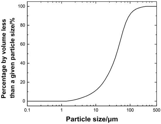
Figure 1.
Particle analysis curve of waste slurry.
- (2)
- MgO
In this experiment, STARMAG150 active MgO was used. It appears as a pure white, ultrafine powder (Figure 2a), with a density of 0.48 g/cm3 and a MgO content of up to 98%. Its chemical composition and content are listed in Table 2. STARMAG150 exhibits excellent reactivity and high density.
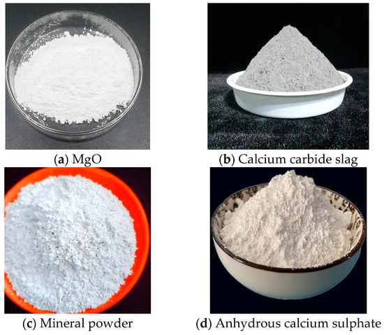
Figure 2.
Test materials.
Table 2.
Chemical composition of active MgO.
- (3)
- Calcium carbide slag
This experiment used high-quality, first-grade carbide slag powder, which is fine-textured and gray in appearance (Figure 2b). It exhibits high reactivity, with a particle size ranging from 150 to 400 mesh and a density of 1.5 g/cm3. The specific chemical composition is listed in Table 3.
Table 3.
Chemical composition of calcium carbide slag.
- (4)
- Mineral powder
This experiment used S95-grade slag powder with a density of 2.8 g/cm3, a flow ratio of 98%, a loss on ignition (LOI) of 0.84%, and a moisture content of 0.45%. It appears grayish-white (Figure 2c). The specific chemical composition is listed in Table 4.
Table 4.
Chemical composition of mineral powders.
- (5)
- Anhydrous calcium sulphate, PAM and CO2
The anhydrous calcium sulfate used in this experiment is of analytical reagent (AR) grade (Figure 2d). The specific technical specifications are listed in Table 5.
Table 5.
Table of technical conditions for anhydrous calcium sulphate.
The anionic polyacrylamide (PAM), also known as analytical-grade PAM, has a PAM content of no less than 90% and a hydrolysis degree of 30%. It appears as a white crystalline substance, with a pH range of 5.0–7.0 and an anionic value of 1.2–1.6. It exhibits excellent flocculation performance.
The CO2 gas used is high-purity, food-grade CO2 with a purity of up to 99%.
- (6)
- Foaming agents
Since lightweight carbonated solidified slurry is alkaline, using an acidic foaming agent would cause CO2 foam to dissolve easily within the slurry, leading to severe defoaming and collapse, which hinders strength development. Therefore, the foaming agent used in this study was an alkaline-type foaming agent mainly composed of anionic surfactants (e.g., sodium dodecylbenzene sulfonate), alkaline additives (sodium hydroxide), and a small amount of stabilizers (lignosulfonate and cellulose ether). The alkaline environment reduces the surface tension of the solution, promoting foam generation, while the stabilizers enhance the foam’s stability and resistance to collapse. Although it readily reacts with CO2, its effects can be mitigated through pre-treatment. The CO2 foam generated with an alkaline foaming agent remains largely insoluble in the slurry, preventing significant collapse and minimizing its impact on strength. Additionally, the foam expansion ratio is high, and foam stability is well-maintained. When air is used for foaming, the resulting foam density is 40 kg/m3, whereas CO2 foaming results in a foam density of 80 kg/m3. The binder system was designed as a combination of reactive MgO, Calcium carbide slag, and Mineral powder to exploit their synergistic effects. Reactive MgO hydrates and carbonates, contributing both strength and CO2 sequestration. Calcium carbide slag rapidly hydrates to provide alkalinity and Ca2+, promoting the dissolution of mineral powder and precipitation of CaCO3. Mineral powder, as a latent hydraulic material, reacts with Ca2+ and OH− to form C–S–H gel, further densifying the matrix. This composite design overcomes the limitations of single binders—such as the slow carbonation of MgO, the expansive behavior of calcium carbide slag, and the low reactivity of mineral powder—and achieves a balance of strength, stability, and carbon fixation, making it particularly suitable for high water-content waste slurry.
2.2. Specimen Preparation
The preparation flowchart is shown in Figure 3 with the following steps:
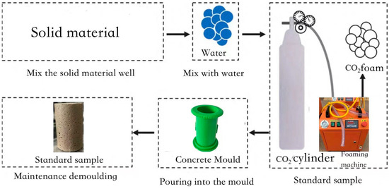
Figure 3.
Schematic diagram of the specimen preparation process.
(1) Preparation of Mixed Slurry: The slurry collected from the construction site undergoes stirring and drying as pre-treatment before being stored in a sealed container for later use. Prior to testing, high-water-content slurry is prepared at a preset water content of 200%. The solidifying agent is then weighed according to the mix design calculations. First, the powdered solidifying agent is mixed evenly and then gradually added in two separate batches to the prepared high-water-content slurry while stirring. Each batch is stirred for 3 min to ensure thorough mixing of the solidifying agent and slurry.
(2) Preparation of CO2 Bubble Clusters: CO2 foaming requires pre-treatment of the foaming agent. Since the foaming agent is alkaline and readily reacts with CO2, and CO2 exhibits some solubility in solution, the foam tends to be unstable and dissipates quickly. Therefore, pre-treatment is necessary. The foaming agent is diluted at a 1:40 ratio before CO2 gas is introduced, with the pressure adjusted to 200 kPa. Once foaming stabilizes, the gas inlet valve is closed, and the mixture is left undisturbed for 20 min to allow full reaction between CO2 and the foaming agent. During this period, the foaming machine pressure is maintained; if pressure drops, the inlet valve is reopened to restore stability. The foaming machine is then activated, and foaming pressure is adjusted. Once stable foaming is achieved, the foam is left undisturbed for 10 min to ensure uniform and stable formation.
(3) Preparation and Pouring of Lightweight Slurry: The foam, which has been left to rest, is measured using a graduated cylinder according to the mix ratio and added to the prepared slurry. The mixture is then stirred for 1 min to ensure thorough and uniform mixing for carbonation. The mixed slurry is poured into the mold for the experiment in three batches. Due to the self-compacting nature of foam-based lightweight slurry, gentle vibration is sufficient to achieve uniform filling. Finally, a transparent plastic film is placed over the poured mold to prevent moisture loss.
(4) Curing: The cast specimens are placed in a standard curing chamber set to a temperature of 20 °C (±1 °C) and humidity of 99% for standard curing. The curing conditions of 20 ± 1 °C and 99% relative humidity were selected in accordance with the Standard for Geotechnical Testing Methods (GB/T 50123-2019) [20] and the Technical Specification for Bubble-Mixed Lightweight Soil Filling Engineering (CJJ/T177-2012) [22], which specify these parameters as reference conditions for evaluating stabilized soils. This choice also reflects field environments where lightweight carbonated stabilized soil is typically applied, such as tunnel backfilling and foundation treatment. In such scenarios, the soil mass remains in a nearly saturated state with minimal temperature fluctuation, providing a similar hydrothermal environment to that of the laboratory curing chamber. Therefore, adopting these curing conditions not only ensured methodological consistency but also enhanced the representativeness and applicability of the experimental results to practical engineering situations. After 48 h, the specimens are demolded and covered with plastic film before being returned to the curing chamber for continued standard curing until the required age for testing is reached.
2.3. Test Methods
In this study, the dosages of mineral powder, active MgO, and carbide slag were selected as factors for a three-factor, three-level orthogonal experiment using the CO2 foaming method. The aim was to investigate the impact of different factors on the physical and mechanical properties of high-water-content waste slurry after 28 days of curing. Carbide slag, as an alkaline activator, provides an alkaline environment to activate both the mineral powder and active MgO. Since the waste slurry used in this study has not undergone a mud-water separation process, anhydrous calcium sulfate and PAM were added as additives to reduce the water content and achieve better curing results. Based on the experimental results from Zhou [23] and Yang [24], the anhydrous calcium sulfate content was set at 5% of the total mass of the waste slurry, and the PAM content was set at 0.5%. The mix ratio designs for the orthogonal experiment are shown in Table 6 and Table 7. The level numbers in the tables correspond to the respective dosages of each factor.
Table 6.
Orthogonal Test Benchmark Proportioning Test Sheet.
Table 7.
Wet weight test results.
The mix percentages listed in Table 6 were determined based on a combination of technical specification guidance (CJJ/T177-2012) [22], previous studies on MgO–slag systems, and laboratory trial mixes. Preliminary tests indicated that MgO contents above 15% led to cracking due to expansion, while contents below 10% limited carbonation strength. Calcium carbide slag contents exceeding 10% reduced stability, whereas mineral powder contents below 20% resulted in insufficient gel formation. Accordingly, the selected ranges (MgO 10–15%, Calcium carbide slag 5–10%, Mineral powder 20–30%) provided a balance of strength, volume stability, and carbon fixation.
In this study, the material dosage is defined as the mass of each added material as a percentage of the total mass of waste slurry. The CO2 foam dosage refers to the volume of CO2 foam added as a percentage of the total volume of lightweight carbonized solidified slurry. Based on existing research [25], the CO2 foam dosage was set at 35% of the total volume. In this study, the CO2 foam dosage was set at 35% of the total volume of the lightweight carbonated stabilized slurry. This value was determined with reference to the Technical Specification for Bubble-Mixed Lightweight Soil Filling Engineering (CJJ/T177-2012) [22] and relevant studies on CO2 foamed lightweight soils [25]. Preliminary trials conducted in our laboratory indicated that when the foam content is below 30%, the slurry density remains relatively high, reducing the lightweight effect, while contents above 40% lead to excessive pore formation and a significant decline in strength. Therefore, a dosage of 35% was selected as a balance between strength and density. Although systematic optimization of foam dosage was not the primary focus of this study, the chosen value ensures good comparability with previous research and stable performance within the composite cementitious material system adopted herein. The mix ratio calculation method follows the Technical Specification for Bubble-Mixed Lightweight Soil Filling Engineering (CJJ/T177-2012) [22]. An orthogonal experimental design was used to establish the baseline mix ratio.
Before casting the specimens into molds, the slurry flow value and wet density before 28 days of standard curing were measured. Unconfined compressive strength (UCS) tests were conducted at curing ages of 7, 14, and 28 days to obtain UCS values, stress–strain curves, and deformation modulus. To assess data variability and quantify the relative influence of the three factors used in the orthogonal design (mineral powder, active MgO, and carbide slag), descriptive statistics and an analysis-of-variance (ANOVA) partitioning were performed on the 28-day unconfined compressive strength (UCS) values The orthogonal L9(3^3) matrix used in this study contains single observations per treatment cell; therefore, the ANOVA was carried out by decomposing the total sum of squares into contributions attributable to each factor (i.e., the classical orthogonal decomposition). We report the mean and standard deviation for the set of orthogonal experiments, the sums of squares, mean squares, F-statistics, and corresponding p-values.
Additionally, microstructural analysis was performed using X-ray diffraction (XRD) and scanning electron microscopy (SEM) to examine the microstructural characteristics.
3. Test Results and Analyses
3.1. Wet Density
Table 7 presents the wet density test results of lightweight carbonized solidified slurry after 28 days of standard curing.
As shown in Table 7, when the CO2 foam content was fixed at 35%, the maximum wet density of the lightweight carbonized solidified slurry reached 14,760 kg/m3. In contrast, when the slag powder content was 25% and the active MgO content was 15%, the wet density decreased to 12,150 kg/m3. A range analysis based on the orthogonal test results was conducted to determine the optimal dosage of the solidifying agents and assess the influence of different factors on wet density. The R-value was used to quantify the impact of each factor, where a higher R-value indicated a greater influence within the tested range. This allowed for a more precise identification and ranking of the most significant variables in the orthogonal test. The range analysis results for wet density are presented in Table 8.
Table 8.
Extreme variance analysis of wet weight results of orthogonal tests.
From Table 8 and Figure 4, it can be observed that the factors influencing the wet density of lightweight carbonized solidified slurry, in descending order of impact, are: slag powder content, active MgO content, and carbide slag content. Due to the higher density of slag powder, its content has a more significant impact on the wet density. Although active MgO has the lowest density, as its content increases, the carbonized solidification products also increase. Therefore, when both slag powder and active MgO contents are at their minimum levels, the wet density of the lightweight carbonized solidified slurry is the lowest. In conclusion, the minimum wet density occurs when slag powder content is 25%, active MgO content is 10%, and carbide slag content is 7.5%.
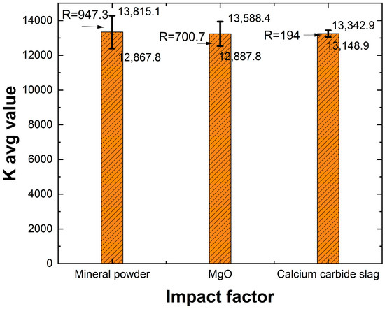
Figure 4.
Histogram of extreme deviation of wet weights.
3.2. Flowability
The flowability of foam lightweight soil is a key indicator for evaluating its construction performance, directly influencing the material’s self-compaction, construction efficiency, and mechanical properties after hardening. The flowability of the slurry was tested in accordance with the Technical Specification for Bubble-Mixed Lightweight Soil Filling Engineering (CJJ/T 177-2012) [22]. Flowability, also referred to as flow value, is an indicator of the slurry’s workability. According to the specification, the typical flowability of bubble-mixed lightweight soil ranges from 160 to 200 mm. The test was performed using a smooth porcelain tile as the base and a cylindrical mold specifically designed for lightweight soil flowability measurement (inner diameter 80 mm, height 80 mm, wall thickness 2 mm). The mold was placed horizontally on the tile and filled with freshly mixed slurry. The surface was leveled with a flat spatula while avoiding slurry spillage outside the mold. The mold was then carefully lifted vertically, allowing the slurry to spread into a circular disc. After 1 min, the average diameter of the spread was measured along two perpendicular directions using a vernier caliper, accurate to 1 mm. The procedure was repeated three times, and the arithmetic mean was taken as the final flow value of the slurry. Table 9 presents the flowability test results of the lightweight carbonized solidified slurry samples after 28 days of standard curing. It can be observed that when the CO2 foam content is 35% of the total volume, the flowability of the lightweight carbonized solidified slurry ranges from 118 to 209 mm.
Table 9.
Orthogonal test flowability test results.
A range analysis was conducted based on the orthogonal test results to determine the effect of different mix proportions on the flowability of lightweight carbonized solidified slurry.
As shown in Table 10 and Figure 5, the factors influencing the flowability of lightweight carbonized solidified slurry, in descending order, are carbide slag content, slag powder content, and active magnesium oxide content. The primary component of carbide slag is Ca(OH)2, which exhibits strong alkalinity. It provides the necessary alkaline environment for the hydration reaction of slag and other geopolymeric materials, breaking the silica-oxygen protective layer on the slag surface and releasing Mg2+ and Ca2+ to facilitate hydration. Therefore, as the carbide slag content increases, the hydration reaction of the lightweight carbonized solidified slurry becomes more thorough, consuming more water from the original waste slurry and leading to a decrease in flowability. When the carbide slag content is reduced to 4%, the solidification effect is relatively poor, but the flowability improves. In summary, the optimal mix proportions for maximizing the flowability of lightweight carbonized solidified slurry are 25% slag powder, 12.5% active magnesium oxide, and 4% carbide slag.
Table 10.
Polar analysis of orthogonal test mobility results.
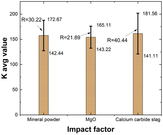
Figure 5.
Histogram of extreme deviation of fluidity.
3.3. Unconfined Compressive Strength
Table 11 presents the unconfined compressive strength (UCS) test results of lightweight carbonized solidified slurry specimens from various orthogonal test groups after 28 days of standard curing.
Table 11.
Orthogonal test and statistical analysis results of unconfined compressive strength test.
The UCS test results indicate that when the CO2 foam content is 35%, the 28-day UCS of the lightweight carbonized solidified slurry ranges from 0.11 to 0.48 MPa. The highest UCS of 0.48 MPa is achieved when the mineral powder content is 25%, the active MgO content is 12.5%, and the carbide slag content is 7.5%. A range analysis based on the orthogonal test results is conducted to determine the effect of different factor contents on the UCS of the solidified slurry.
As shown in Table 12 and Figure 6, the factors affecting the 28-day UCS of lightweight carbonized solidified slurry, ranked in descending order of influence, are mineral powder content, carbide slag content, and active MgO content. The maximum UCS is achieved when the mineral powder content is 25%, active MgO content is 12.5%, and carbide slag content is 7.5%. This is the optimal factor levels. The selection of the optimal factor levels (25% mineral powder, 12.5% active MgO, and 7.5% carbide slag) can be explained by considering both material reactivity and practical performance. A mineral powder dosage of 25% supplies adequate CaO and SiO2 to promote the formation of secondary C–S–H gels, while avoiding excessive density increase that occurs when its content exceeds 25%. For active MgO, a dosage of 12.5% ensures sufficient carbonation products such as nesquehonite and hydromagnesite, which strengthen the pore structure, while preventing the microcracking and strength reduction often observed when MgO exceeds 15%. For carbide slag, 7.5% provides an optimal alkaline environment to activate both mineral powder and MgO, producing a dense matrix, whereas higher dosages tend to leave unreacted particles and reduce overall strength. This balance explains why the orthogonal test identified 25% mineral powder, 12.5% MgO, and 7.5% carbide slag as the most effective proportions, yielding superior strength, lower density, and good flowability. Representative UCS specimens after testing are shown in Figure 7. The samples generally exhibited brittle failure with visible vertical cracks and localized shear planes.
Table 12.
Extreme variance analysis of the results of the orthogonal test for unconfined compressive strength.
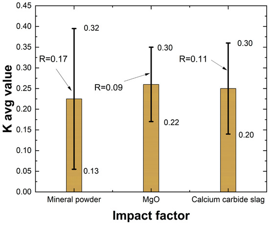
Figure 6.
Histogram of extreme deviation of unconfined compressive strength.
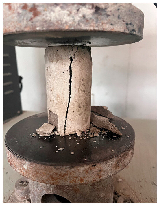
Figure 7.
UCS failure patterns.
Table 11 is statistical analysis of UCS results. To evaluate reproducibility, each orthogonal group (Z1–Z9) was tested in triplicate. The mean 28-day UCS values ranged from 0.11 to 0.48 MPa depending on the factor levels, while the within-group standard deviations were very low (0.002–0.009 MPa), confirming the reliability of the measurements. Thus, the wide variation observed across groups mainly reflects differences in material proportions rather than experimental inconsistency.
An ANOVA (in Table 13) was further carried out to apportion the variance among the three factors. The results indicated that mineral powder content explained the largest proportion of the variance in UCS, followed by carbide slag and MgO. Although no factor effect reached statistical significance at the 5% level, the variance decomposition provides useful insight into the relative contributions of each factor. Together, the mean ± standard deviation reporting and ANOVA results demonstrate both the reproducibility of the measurements and the robustness of the observed factor trends.
Table 13.
ANOVA analysis results.
3.4. Effect of Active MgO Dosage on Unconfined Compressive Strength
With the optimal contents of mineral powder and carbide slag, the influence of varying active MgO content on UCS is investigated, as shown in Figure 8.
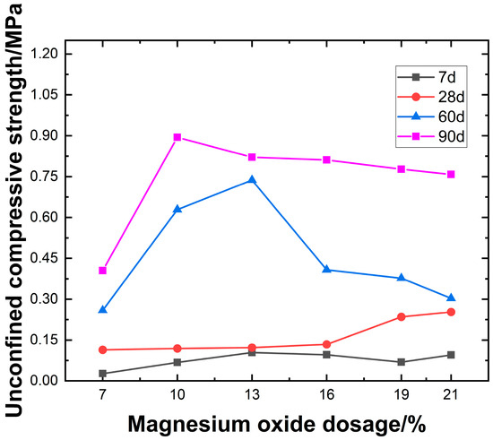
Figure 8.
Effect of active magnesium oxide dosage on unconfined compressive strength.
As shown in Figure 8, the content of active MgO has a significant effect on compressive strength. At a curing age of 7 days, the compressive strength of lightweight carbonated solidified slurry ranges from 0.027 to 0.104 MPa. It initially increases and then decreases with increasing active MgO content, reaching a peak early strength of 0.104 MPa at 13% MgO content. At 28 days of curing, the compressive strength ranges from 0.114 to 0.253 MPa and generally increases with higher active MgO content. At lower MgO contents, the impact on strength is minimal, while the most rapid strength gain occurs in the range of 16–19% MgO. The highest strength of 0.253 MPa is observed at 21% MgO content. For longer curing periods of 60 and 90 days, the strength increases significantly, ranging from 0.259 to 0.894 MPa. The compressive strength initially rises and then declines with increasing active MgO content, with peak values observed at 10% and 13% MgO content.
With increasing active MgO content, the alkaline environment provided by carbide slag promotes hydration reactions in the lightweight carbonated solidified slurry, leading to a higher content of hydration products such as Mg(OH)2. These products subsequently react under high-concentration CO2 foam conditions, forming granular nesquehonite crystals that fill the pores in the slurry and aggregate the slurry particles through encapsulation and cementation. As the active MgO content further increases, the number of internal pores in the slurry decreases, resulting in a denser structure. This indicates that the carbonation products primarily originate from the hydration product Mg(OH)2. Enhancing the active MgO content facilitates the carbonation reaction, thereby improving the unconfined compressive strength of the slurry. However, when the active MgO content is excessively high, excessive carbonation products coat the unreacted raw materials, hindering both hydration and carbonation reactions. As a result, the unconfined compressive strength of the lightweight carbonated solidified slurry decreases.
3.5. Stress–Strain Curves
The 28-day stress–strain curves of the specimens were obtained through unconfined uniaxial compression tests, as shown in Figure 9. The stress failure process of the lightweight carbonated solidified slurry can be divided into three stages: Linear Stage: Before reaching the peak stress, the axial stress increases linearly with axial strain, indicating elastic deformation without structural damage or crack formation. Nonlinear Stage: The axial stress increases nonlinearly with axial strain until the peak stress is reached, at which point plastic deformation occurs and cracks begin to form. Strain-Softening Stage: After reaching the peak stress, the stress gradually decreases with increasing axial strain as internal cracks rapidly propagate until complete failure of the specimen. At a curing age of 28 days, the compressive strength of the lightweight carbonated solidified slurry ranges from 0.114 to 0.253 MPa, showing a continuous increasing trend with increasing active MgO content. When the active MgO content is relatively low, its effect on the compressive strength is minimal. The most rapid strength increase occurs within the MgO content range of 16–19%. This is attributed to the enhanced hydration reactions in the alkaline environment provided by carbide slag as the active MgO content increases, leading to a higher concentration of hydration products such as Mg(OH)2. These products subsequently react under high-concentration CO2 foam conditions, forming granular nesquehonite crystals that fill the pores in the slurry and aggregate the slurry particles through encapsulation and cementation. As the active MgO content further increases, the number of internal pores in the slurry decreases, resulting in a denser structure. This indicates that the carbonation products primarily originate from the hydration product Mg(OH)2. Enhancing the active MgO content facilitates the carbonation reaction, thereby improving the unconfined compressive strength of the slurry. When the active MgO content reaches 21%, the compressive strength of the lightweight carbonated solidified slurry peaks at 0.253 MPa.
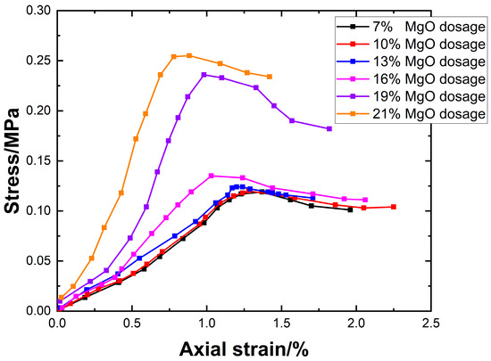
Figure 9.
Stress–strain curves versus active magnesium oxide dosage.
As shown in Figure 9, the peak stresses of the low-dosage groups (7% and 10%) are 0.112 MPa and 0.113 MPa, respectively, occurring at approximately 1.25% strain. For the intermediate dosage group (13%), the peak stress is around 0.125 MPa. In the high-dosage groups (16%, 19%, and 21%), the peak stress gradually increases to 0.136–0.253 MPa, while the peak position shifts significantly to the left.
By selecting samples with a slag content of 25%, magnesium oxide content of 13%, and calcium carbide content of 7.5%, the relationship between stress–strain curves and curing age was analyzed, as shown in Figure 10. It can be observed that as the curing age increases, the peak stress continuously rises, and the failure strain gradually decreases with the increase in peak stress. This indicates that the strength of the sample continues to rise during the curing process, and between 28 and 60 days, the peak stress increases sharply, with the ability to resist deformation continuously improving. At the same time, the material’s brittleness increases.
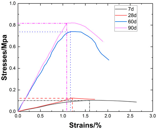
Figure 10.
Stress–strain curves versus age of conservation.
3.6. Modulus E50
The deformation modulus E50 refers to the ratio of stress to strain of lightweight soil under unconfined conditions when the stress is 50% of the compressive strength [26]. It reflects the material’s ability to resist deformation and can be obtained by analyzing the stress–strain curve.
The deformation modulus of carbonated lightweight soil is shown in Figure 11. Analysis of Figure 11a reveals that, as the amount of active MgO increases, the elastic modulus of the material at different ages shows a differentiated trend. The elastic modulus at 90 days increases significantly with the amount of MgO, reaching a peak (approximately 1.7–1.8 MPa) at 19–21%. The slope of the curve is large, with small changes, indicating that high MgO content under long-term curing promotes hydration reactions and structural densification for effective reinforcement. At 60 days, the overall increase is lower than at 90 days but still shows an upward trend. The elastic modulus at 7 days and 28 days is limited by insufficient hydration of active particles, with low dosages (7–13%) showing only a slight increase to 0.03 MPa. It is worth noting that when the dosage exceeds 16%, the elastic modulus at 7 days slightly decreases. This phenomenon reveals that the reinforcing effect of active MgO is highly dependent on the curing age. High dosages require long-term curing to achieve full effectiveness, while the dosage at early stages should be controlled to avoid negative effects.
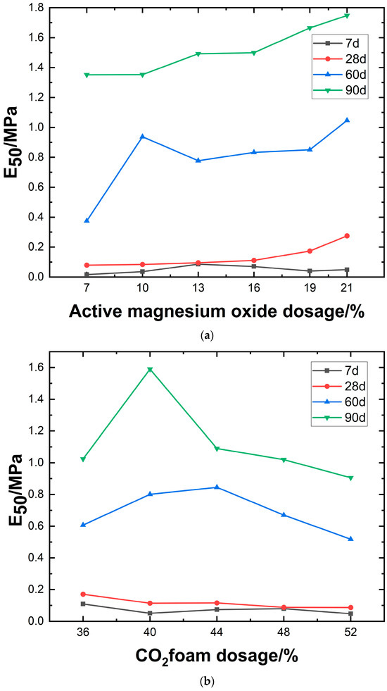
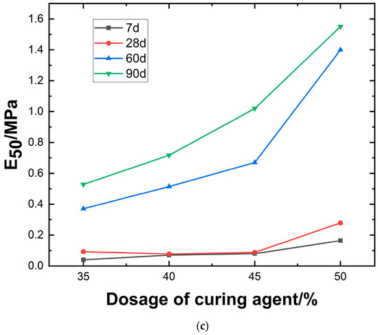
Figure 11.
Relationship between modulus of deformation and magnesium oxide dosage, CO2 foam dosage, and curing agent dosage.
As shown in Figure 11b, the elastic modulus of the material exhibits a differentiated trend with increasing CO2 foam content at different curing ages. At 90 days, the elastic modulus peaks at 1.6 MPa when the CO2 foam content reaches 40%, then gradually decreases to 0.89 MPa as the content increases to 52%. This suggests that under long-term curing, CO2 foam achieves optimal reinforcement by optimizing pore structure or promoting hydration reactions. At 60 days, the variation in E50 is relatively small but follows a general trend of initial increase followed by a decrease, peaking at 0.83 MPa. This indicates that the material stabilizes gradually under mid-term curing. For the 7-day and 28-day groups, the elastic modulus is limited by insufficient hydration of active particles. At low foam contents (36–40%), instability in the foam structure or incomplete hydration results in a strength decline. In the 7-day group, higher foam content (≥40%) leads to only a slight increase, reaching 0.09 MPa. Notably, when the foam content exceeds 40%, the elastic modulus in the 90-day group declines, suggesting the existence of an optimal dosage threshold. This phenomenon highlights the dual effect of CO2 foam in carbonated lightweight solidified slurry: moderate addition enhances long-term performance by optimizing structure, whereas excessive incorporation exacerbates pore defects and compromises mechanical stability. Precise dosage control is necessary based on specific service conditions.
As shown in Figure 11c, the chart compares the effects of different stabilizer dosages and curing durations on the elastic modulus, revealing the trend of material strength variation over time and mix proportions. As the dosage of curing agent increases from 35% to 50%, E50 exhibits an upward trend across all curing ages. The most significant increase occurs at 90 days, reaching a peak of 1.6 MPa, indicating that prolonged curing enhances hydration through continued stabilizer activity. At 7 days, the strength increase is minimal (approximately 0.04–0.18 MPa), reflecting incomplete activation of early-stage hydration. At 28 and 60 days, the modulus stabilizes within the range of 0.3–1.4 MPa, indicating that primary hydration reactions are largely completed during the mid-term, leading to gradual densification. The data suggest the presence of an optimal dosage window (about 45%), beyond which E50 experiences the most significant growth.
Figure 12 illustrates the relationship between the deformation modulus E50 and the unconfined compressive strength qu. Regression analysis yields a well-fitted linear function: E50 = 1.07qu − 0.045. Under identical conditions except for varying magnesium oxide content, the relationship between E50 and qu falls within the range of E50 = 0.698qu − 0.03 to E50 = 1.73qu − 0.074.
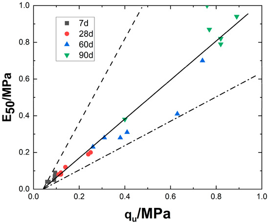
Figure 12.
Relationship between modulus of deformation and unconfined compressive strength.
Further examination of Figure 12 reveals that as the curing period increases, data points shift toward higher values. This trend is closely related to the physical and mechanical properties of lightweight carbonated stabilized slurry. The simultaneous increase in strength and modulus reflects the continuous optimization of the material’s internal microstructure. Specifically, in the early stage (7 days), the data points are concentrated in the low-strength (approximately 0.04–0.1 MPa) and low-modulus (0.03–0.1 MPa) regions, indicating that carbonation is not yet complete. At this stage, the soil exhibits a high porosity, and cement hydration products have not yet formed an effective interwoven structure. In the intermediate stage (28–60 days), red circles and blue triangles transition to the mid-to-high value range (qu: 0.1–0.7 MPa, E50: 0.08–1.0 MPa). This corresponds to an increase in carbonation gel and a reduction in porosity, where the combined effect of enhanced interparticle friction and cementation leads to simultaneous increases in strength and modulus. In the long-term stage (90 days), green inverted triangles reach peak values (qu: 0.9 MPa, E50: 1.0 MPa), indicating further carbonation, increased crystal size, and the formation of a dense network structure, marking the transition into a stable hardening phase.
This phenomenon essentially represents a time-driven hydration–carbonation coupling effect. As the curing period extends, CO2 reacts with the hydration products of magnesium oxide to form carbonates that fill the pores, ultimately leading to a linear improvement in macroscopic mechanical properties (strength and modulus).
4. Discussion
4.1. Mechanisms of Hydration and Carbonation Reactions
The experimental materials used contain a high proportion of reactive MgO, CaO, and Ca(OH)2, which undergo hydration upon contact with water to form brucite, accompanied by the generation of Ca(OH)2, as shown in Equation (1). In a humid environment with CO2 foam, brucite continues to absorb water and undergo carbonation, primarily forming nesquehonite, hydromagnesite, and dypingite. During this process, calcium-based compounds carbonate into CaCO3. The complete reaction process is presented in Equation [27].
As shown in Figure 13, the XRD relative intensity of several diffraction peaks increases with rising MgO content. The vertical axis of Figure 13 indicates the relative diffraction signal intensity (a.u.), where a higher peak reflects either a stronger diffraction capacity of the corresponding crystal plane family or a greater abundance of crystalline phases with that orientation in the sample. Due to the high quartz content in the waste slurry, the XRD spectrum exhibits strong peak intensities. After carbonation and solidification, numerous low-intensity peaks emerge, indicating the formation of substantial hydration and carbonation products. The identified phases include ettringite, magnesite, aragonite, spherulitic aragonite, calcite, dolomite, and MgO. Zhang et al. [28] reported that the carbonation of Mg2+ ions and the formation of hydrated hydroxy-magnesium carbonates are the primary contributors to the strength of MgO-based carbonated foam lightweight soil. Li et al. [16] suggested that the strength development of reactive MgO cement depends on the extent of hydration and carbonation reactions. As shown in Figure 8, with increasing reactive MgO content, both the number and intensity of magnesite peaks increase, indicating that higher MgO content enhances the internal carbonation reaction, leading to greater carbonate formation. However, unreacted MgO slightly increases when the MgO content reaches 21%, suggesting a saturation threshold for carbonation.
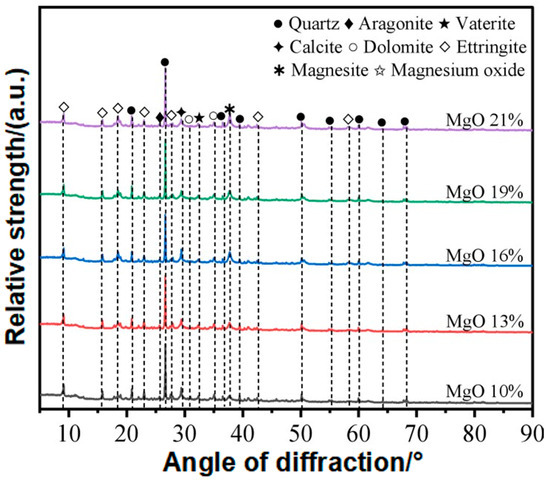
Figure 13.
XRD spectra of lightweight carbonized cured slurry.
Figure 14 presents the localized microstructural characteristics of the sample at a magnification of 5000×. The hydration product brucite exhibits weak cementation capacity [29] and does not significantly contribute to strength development. However, its subsequent carbonation leads to the formation of spherical nesquehonite, hydromagnesite, and other basic magnesium carbonates, which possess superior cementation properties, higher strength, and greater hardness. During the reaction, these carbonates undergo volumetric expansion, filling internal pores while simultaneously bonding solid particles. This densifies the sample structure, enhancing its mechanical performance. Based on the microstructural observations and XRD results, the transformation pathway of reaction products can be summarized as “Reactive MgO → Brucite → Hydromagnesite/Nesquehonite/Dypingite.” The spherical structures observed in the figure correspond to nesquehonite. These spheres facilitate physical encapsulation and chemical bonding between soil particles and impurities in the waste slurry, acting as “bridging agents.” This bridging effect forms an adhesive layer between particles, significantly enhancing interparticle friction and the efficiency of normal stress transmission. Additionally, nesquehonite fills pores, thereby reducing porosity. Nesquehonite rapidly forms in the early curing stage (7–28 days), contributing to the initial compressive strength. The needle-like or fibrous crystals observed along pore walls correspond to hydromagnesite. These crystals align directionally to form a network structure, continuing to develop in the later curing stage (60–90 days). In conjunction with nesquehonite, they enhance strength, enabling the material to reach 0.894 MPa at 90 days. As hydromagnesite grows along pore walls, it “anchors” loose particles within a dense network, restricting particle displacement. Meanwhile, its fibrous structure absorbs external stress energy, delaying crack propagation. The plate-like or fibrous amorphous gel observed in the figure corresponds to C-S-H gel. This gel, together with nesquehonite, forms a three-dimensional network, enhancing overall structural integrity. Additionally, it improves the interfacial bonding between soil particles and the cementing phase, reducing weak zones.
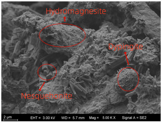
Figure 14.
Microstructure characterization at 5000 times magnification.
4.2. Effect of MgO Content on Relative Strength and Microstructural Mechanisms
As shown in Figure 13, the enhanced peaks corresponding to nesquehonite, hydromagnesite, and brucite demonstrate that higher MgO dosage promotes the hydration–carbonation reactions of MgO, leading to more carbonate and hydroxide products. These crystalline phases provide rigid fillers and contribute to microstructural densification.
SEM images (Figure 14) support this interpretation. With increasing MgO content, more spherical and fibrous carbonate products are observed filling pores and coating soil particle surfaces, while C–S–H gel generated by the activation of Mineral powder further bonds particles together. This microstructural evolution reduces porosity, improves interparticle contact, and enhances matrix continuity. Consequently, higher MgO content results in improved mechanical performance of the composite system, as reflected in the microstructural evidence provided by XRD and SEM.
4.3. Evolution of Carbon–Magnesium Reactions in Lightweight Carbonized Cured Muds
Based on the strength formation mechanism of lightweight carbonated solidified slurry, the reaction process can be divided into two stages: hydration and carbonation. (1) Hydration stage: Magnesium oxide (MgO) and calcium oxide (CaO) react with water to form brucite (Mg(OH)2) and Ca(OH)2. (2) Carbonation stage: Brucite further reacts with water and CO2 to form nesquehonite (Mg2CO3(OH)2·3H2O), hydromagnesite (Mg5(CO3)4(OH)2·4H2O), and dypingite (Mg5(CO3)4(OH)2·5H2O). Simultaneously, calcium hydroxide reacts with water and CO2 to form CaCO3. A schematic diagram illustrating the microstructural reaction process of lightweight carbonated solidified soil is proposed, as shown in Figure 15.
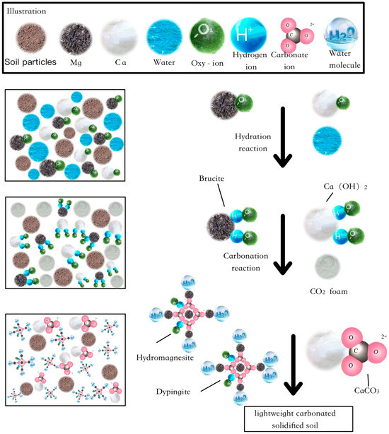
Figure 15.
Schematic diagram of the microscopic reaction of lightweight carbonized cured slurry.
4.4. Advantages of the CO2 Foaming–Carbonation Composite Method over Traditional Approaches
Conventional MgO carbonation solidification has been widely investigated for soft soils and low-water-content sediments, where reactive MgO undergoes hydration to form brucite, followed by carbonation to generate nesquehonite and hydromagnesite, thereby enhancing strength. While these studies have demonstrated considerable improvements in mechanical behavior, their applicability to high-water-content waste slurry is limited. Excess pore water often dilutes alkaline conditions, suppresses the carbonation kinetics, and causes foam instability or pore collapse during curing. As a result, traditional MgO carbonation methods are unable to simultaneously achieve effective lightweighting, strength development, and carbon sequestration in such challenging slurry systems.
The composite approach proposed in this study integrates MgO–mineral powder–carbide slag binders with CO2 foaming–carbonation, thus establishing a synergistic chemo-physical pathway. Compared with conventional methods, several advantages can be highlighted. First, the incorporation of CO2 foam not only reduces density but also promotes a more uniform distribution of CO2 within the slurry, improving carbonation efficiency across the matrix. Second, the foaming process creates a controlled porous structure that is subsequently stabilized by carbonate precipitation, preventing the random pore collapse typically observed in conventional lightweight soils. Third, the addition of carbide slag provides an alkaline environment that accelerates the dissolution of mineral powder and MgO, leading to enhanced formation of C–S–H gel and carbonate crystals. This multi-component activation mechanism ensures that both mechanical strength and CO2 fixation are optimized.
Furthermore, the method demonstrates superior performance in addressing the critical challenge of high-water-content waste slurry. Whereas ordinary cement- or lime-based stabilizers tend to suffer from strength loss and durability issues in water-rich environments, the CO2 foaming–carbonation system effectively transforms excess water into part of the reaction medium, thus mitigating its adverse effects. The experimental results in this study confirm that the unconfined compressive strength of the proposed material is significantly higher than that of conventional foamed lightweight soils, while still maintaining low density.
The superiority of such coupled methods can also be understood in light of recent advances in other fields. For instance, Wang et al. [30] demonstrated that thermo-mechanical cyclic treatments, specifically heating–cryogenic cooling cycles, could markedly accelerate microcrack development and permeability evolution in low-permeability coal, outperforming conventional single-mechanism approaches. Analogously, our study shows that the coupling of foaming and carbonation enables more efficient structural modification of slurry than traditional single-phase MgO carbonation. The synergy between gas–liquid foaming dynamics and carbonation reactions provides an additional driving force that conventional approaches inherently lack.
In summary, the CO2 foaming–carbonation composite method achieves a unique balance of lightweighting, strength improvement, and carbon sequestration. By overcoming the limitations of traditional MgO carbonation and conventional cement-based stabilizers, it offers a more sustainable and practical solution for the stabilization and utilization of high-water-content construction waste slurry. This dual advantage not only enhances the mechanical performance of the material but also contributes to carbon reduction in the construction sector, underscoring its potential for large-scale engineering applications.
4.5. Permeability Considerations and Study Limitations
It should be noted that the present evaluation mainly relied on E50, while permeability—a critical indicator of durability and seepage resistance—was not experimentally determined in this study. Microstructural analyses indicate that carbonation products and C–S–H gel densify the pore structure and are expected to reduce permeability; however, this remains to be verified. Future work will therefore include systematic permeability measurements (e.g., falling head and NMR-based pore connectivity tests) to establish a direct link between mechanical behavior, permeability, and carbon sequestration performance.”
4.6. Comparative Performance Analysis
To provide a quantitative context for the performance of the proposed MgO–Calcium carbide slag–Mineral powder–CO2 foamed system, we compare our results with representative values reported for conventional cementitious foamed lightweight soils (FLS) and for MgO-assisted carbonation systems. Typical cement-based FLS reported in the literature often attain 28-day compressive strengths around 1.0–1.9 MPa at wet densities near 600 kg·m−3 under standard curing conditions, depending on mix design and curing regime [6]. By contrast, alkali-activated or Mineral powder-dominated foamed systems usually show 28-day strengths below 0.4 MPa in many reported cases unless higher binder contents or elevated curing temperatures are applied [31].
In MgO-enhanced carbonation studies, supplementation with reactive MgO and Mineral powder has been shown to notably increase both mechanical strength and CO2 uptake compared with MgO-free systems; recent reports demonstrate multi-fold strength gains and measurable carbonate formation when MgO/GGBS ratios and carbonation conditions are optimized [32].
In this study, under CO2 foam dosage of 35%, the optimal orthogonal mix (mineral powder 25%, MgO 12.5%, Calcium carbide slag 7.5%) achieved a 28-day UCS of 0.48 MPa (range 0.11–0.48 MPa) with corresponding wet-weight results presented in Table 7. While the 28-day UCS value is lower than some high-binder cement-based FLS examples (which generally use higher binder contents or different curing regimens), our system attains comparable or superior strength relative to many low-binder or Mineral powder-based foamed systems at similar or lower effective binder proportions, and—importantly—provides substantially higher potential for CO2 sequestration due to the presence of reactive MgO and carbide-slag derived Ca—both of which promote carbonate formation under CO2-rich foaming/carbonation conditions [32].
Therefore, the quantitative comparison indicates that the proposed MgO–Calcium carbide slag–Mineral powder–CO2 foamed approach occupies a distinct performance: it achieves moderate 28-day mechanical performance at relatively low binder addition while offering enhanced carbon uptake capacity.
4.7. Durability Considerations and Limitations
Although this study extended the experimental period to 90 days, the long-term durability of the lightweight carbonated stabilized slurry has not yet been systematically evaluated. Durability is a critical factor for the field application of cementitious or carbonation-based binders, as external environmental actions such as freeze–thaw cycling, wet–dry alternation, continuous water immersion, and potential leaching of soluble components can significantly affect strength retention and structural stability.
In the present work, the focus was placed on strength development and microstructural evolution within 90 days. Durability-related properties such as freeze–thaw resistance, water stability, and leaching behavior were not tested, which is acknowledged as a limitation of this study. Nevertheless, the observed pore filling and densification effects of carbonate products and C–S–H gel suggest that the material may exhibit favorable resistance to water ingress and freeze–thaw damage compared to traditional cementitious foamed lightweight soils.
Future work will therefore include systematic durability tests, such as cyclic freeze–thaw resistance, long-term immersion stability, and leachate analyses to quantify the release of calcium, magnesium, and potential trace heavy metals. These investigations will provide a more comprehensive understanding of the long-term performance, environmental safety, and engineering applicability of the MgO–Calcium carbide slag–Mineral powder–CO2-foamed stabilization system.
It should be emphasized that this study mainly focused on the mechanical performance and microstructural evolution of the slurry after CO2 carbonation. Although the presence of carbonation products and the observed hardening behavior clearly confirm CO2 absorption and associated environmental benefits, the exact amount of CO2 uptake (kg/m3) was not quantified. This constitutes a limitation of the present work, and future studies will therefore include systematic quantification of CO2 uptake to complement the mechanical performance evaluation.
5. Conclusions
This study investigates the effects of the carbon-magnesium reaction on the physical and mechanical properties of lightweight carbonated solidified soil. Experimental analyses were conducted on its physical-mechanical behavior and microstructure, leading to the following key conclusions:
- (1)
- The combination of mineral powder (25%), reactive MgO (12.5%), and carbide slag (7.5%) significantly enhances the overall performance of the material. Under this mix proportion, the 28-day unconfined compressive strength reaches 0.48 MPa, exceeding the UCS requirement (0.3 MPa) for tunnel backfilling materials specified in CJJ/T177-2012 [22], while maintaining a low wet density. In addition, the slurry exhibits good flowability, ensuring constructability for filling irregular voids. These findings suggest strong laboratory-scale feasibility for tunnel excavation backfilling. Nevertheless, further field-scale validation is required to fully confirm engineering applicability under practical construction conditions.
- (2)
- Under vertical loading, the stress–strain relationship of lightweight carbonated solidified soil exhibits brittle failure characteristics. The simplified expression for the deformation modulus and compressive strength is given as E50 = 1.07qu − 0.045.
- (3)
- Reaction pathway of the carbon–magnesium process: Active MgO and CaO in the waste slurry hydrate to form brucite, which subsequently carbonates into nesquehonite and hydromagnesite in a CO2-rich environment. The calcium-based components react to form calcium carbonate (CaCO3), accompanied by the generation of C-S-H gel, which further binds and fills the pores. Early stage (7–28 days): Nesquehonite provides initial strength by physically encapsulating and chemically bonding the particles. Long-term stage (60–90 days): Hydromagnesite grows directionally along pore walls, forming a dense network structure that significantly enhances compressive strength, reaching 0.894 MPa at 90 days.
- (4)
- The CO2 foaming method enhances the solidification of slurry while achieving carbon sequestration, contributing to the reduction in greenhouse gas emissions. This technique is particularly suitable for civil engineering applications such as tunnel backfilling and foundation reinforcement, demonstrating excellent performance in improving the mechanical properties of high-water-content waste slurry.
Author Contributions
Conceptualization, L.S.; Data curation, W.Y.; Formal analysis, W.Y.; Funding acquisition, L.S.; Investigation, S.W. and H.D.; Methodology, X.D. and C.B.; Project administration, Q.Y.; Resources, B.H., H.D. and C.B.; Software, S.T.; Supervision, Q.Y., B.H., S.T., H.D. and C.B.; Validation, W.Y.; Visualization, W.Y.; Writing—original draft, L.S. and W.Y.; Writing—review and editing, S.W. and X.D. All authors have read and agreed to the published version of the manuscript.
Funding
This research received no external funding.
Data Availability Statement
Data is contained within the article.
Acknowledgments
This work was supported by the National Natural Science Foundation of China (Grant No.: 42177145).
Conflicts of Interest
The authors declare no conflicts of interest.
References
- Gerdemann, S.J.; Dahlin, D.C.; O’Connor, W.K. Carbon dioxide sequestration of magnesium silicate minerrals. In Greenhouse Gas Control Technologies, Proceedings of the 6th International Conference on Greenhouse Gas Control Technologies, Kyoto, Japan, 1–4 October 2002; Elsevier Science: Amsterdam, The Netherlands, 2003. [Google Scholar]
- Weber Consulting. 2024 China Construction Waste Treatment Industry Research and In-Depth Analysis Report; Weber Consulting: Shenzhen, China, 2024. [Google Scholar]
- He, J.; Chu, J.; Tan, S.K.; Vu, T.T.; Lam, K.P. Sedimentation behavior of flocculant-treated soil slurry. Mar. Georesources Geotechnol. 2017, 35, 593–602. [Google Scholar] [CrossRef]
- Yadu, L.; Tripathi, R.K. Effects of granulated blast furnace slag in the engineering behaviour of stabilized soft soil. Procedia Eng. 2013, 51, 125–131. [Google Scholar] [CrossRef]
- Singhi, B.; Laskar, A.I.; Ahmed, M.A. Investigation on Soil–Geopolymer with Slag, Fly Ash and Their Blending. Arab. J. Sci. Eng. 2015, 41, 393–400. [Google Scholar] [CrossRef]
- Wang, Y.; Wan, H.; Liu, H.; Zhang, G.; Xu, X.; Shen, C. Preparation and Properties of Low-Carbon Foamed Lightweight Soil with High Resistance to Sulphate Erosion Environments. Materials 2023, 16, 4604. [Google Scholar] [CrossRef]
- Razeghi, H.R.; Safaee, F.; Geranghadr, A.; Ghadir, P.; Javadi, A.A. Investigating accelerated carbonation for alkali activated slag stabilized sandy soil. Geotech. Geol. Eng. 2024, 42, 575–592. [Google Scholar] [CrossRef]
- Ngo, I.; Ma, L.; Zhao, Z.; Zhai, J.; Yu, K.; Wu, Y. Sol–gel-stabilized CO2 foam for enhanced in-situ carbonation in foamed fly ash backfill materials. Geomech. Geophys. Geo-Energy Geo-Resour. 2024, 10, 80. [Google Scholar] [CrossRef]
- Que, Y.; Chen, X.; Zhu, T.; Zhang, H.; Huang, W.; Leung, K.A.; Jiang, Z.; Xue, B.; Lu, D. Characterizing the Engineering Properties of Marine Sand-Amended Foamed Lightweight Soil: Macroscopic and Microscopic Perspectives. Constr. Build. Mater. 2023, 367, 130305. [Google Scholar] [CrossRef]
- Liu, Y.-Z.; Liu, S.-Y.; Li, H.-J.; Du, G.-Y.; Zhang, C.-Z.; Sun, J.-W. Field investigation on the performance of low-carbon MgO-carbonated composite piles for ground treatments. Can. Geotech. J. 2024, 62, 1–22. [Google Scholar] [CrossRef]
- Harrison, A.J.W. New cements based on the addition of reactive magnesia to Portland cement with or without added pozzolan. In Proceedings of the CIA Conference: Concrete in the Third Millenium, CIA, Brisbane, Australia, 17–19 July 2003; pp. 24–35. [Google Scholar]
- Zhang, Y.; Ong, Y.J.; Yi, Y. Comparison between CaO− and MgO− activated ground granulated blast-furnace slag (GGBS) for stabilization/solidification of Zn-contaminated clay slurry. Chemosphere 2022, 286, 131860. [Google Scholar] [CrossRef] [PubMed]
- Iyengar, S.; Al-Tabbaa, A. Application of two novel magnesia-based cements in the stabilization/solidification of contaminated soils. In GeoCongress 2008: Geotechnics of Waste Management and Remediation; American Society of Civil Engineers: Reston, VA, USA, 2008; pp. 716–723. [Google Scholar] [CrossRef]
- Xue, Q.; Wang, P.; Li, J.S.; Zhang, T.-T.; Wang, S.-Y. Investigation of the leaching behavior of lead in stabilized/solidified waste using a two-year semi-dynamic leaching test. Chemosphere 2017, 166, 1–7. [Google Scholar] [CrossRef]
- Vandeperre, L.J.; Al-Tabbaa, A. Accelerated carbonation of reactive MgO cements. Adv. Cem. Res. 2007, 19, 67–79. [Google Scholar] [CrossRef]
- Li, Z.; Hua, Y.; Chang, Z.; Yue, Y.; Qin, J.; Qian, J. Hydration, carbonation and strength development of reactive MgO cement blended with lime (CaO) under different curing conditions. J. Build. Eng. 2023, 76, 107082. [Google Scholar] [CrossRef]
- Zheng, C.; Cai, G.; Zhong, Y.; Du, G. Experimental Study of Carbide Slag-MgO Stabilized Mud Under Carbonation Condition. Sci. Technol. Ind. 2023, 23, 233–238. (In Chinese) [Google Scholar]
- Yi, Y.; Liska, M.; Unluer, C.; Al-Tabbaa, A. Carbonating magnesia for soil stabilization. Can. Geotech. J. 2013, 50, 899–905. [Google Scholar] [CrossRef]
- Cai, G.; Liu, S.; Du, Y.; Zhang, D.-W.; Zheng, X. Strength and deformation characteristics of carbonated reactive magnesia treated silt soil. J. Cent. South Univ. 2015, 22, 1859–1868. [Google Scholar] [CrossRef]
- GB/T 50123-2019; Standard for Geotechnical Test Methods. China Architecture & Building Press: Beijing, China, 2019. (In Chinese)
- DL/T 5815-2020; Test Procedure for Fixed-wall Mud of Hydropower and Water Conservancy Engineering. China Electric Power Press: Beijing, China, 2020. (In Chinese)
- CJJ/T 177-2012; Technical Specification for Filling Engineering with Bubble Mixed Lightweight Soil. China Planning Press: Beijing, China, 2012. (In Chinese)
- Zhou, D.; Shao, Y.; Cao, Q.; Zhang, B.; Li, J. Experiment research on mixture ratio of stabilizing lacustrine soft soil in Binhu New Area of Hefei Province. J. Pingdingshan Inst. Technol. 2017, 26, 53–60. (In Chinese) [Google Scholar] [CrossRef]
- Yang, S. Experimental Study on Effect of Different Flocculants on Flocculation and Dewatering Performance of Engineering Waste Mud. Sichuan Environ. 2021, 40, 31–37. (In Chinese) [Google Scholar] [CrossRef]
- Cai, G.; Liu, S.; Zhang, Z.; Cao, Q. Preliminary Investigation on Reinforcement of Soft Soil Based on the Method of Carbonation by Carbon Dioxide Foams. Chin. J. Undergr. Space Eng. 2015, 11, 34–38. (In Chinese) [Google Scholar]
- Wang, Z.C.; Liu, S.Y.; Wu, K.; Huang, L.; Wang, J. Study on the mechanical performance of alkali residue-based light-weighted soil. Constr. Build. Mater. 2023, 384, 131353. [Google Scholar] [CrossRef]
- Luo, K.; Li, J.; Lu, Z.; Wang, L.; Deng, X.; Hou, L.; Jiang, J. Preparation and performances of foamed hydraulic lime. Constr. Build Mater. 2021, 290, 32–44. [Google Scholar] [CrossRef]
- Zhang, X.; Wu, K.; Yuan, Z.Y.; Liu, S. Investigations into magnesium oxide carbon sequestration foamed concrete: Mechanical performance, microstructure and environmental benefits. Constr. Build. Mater. 2024, 421, 135679. [Google Scholar] [CrossRef]
- Li, Y.; Emeriault, F.; Kastner, R.; Zhang, Z. Stability analysis of large slurry shield-driven tunnel in soft clay. Tunn. Undergr. Space Technol. 2009, 24, 472–481. [Google Scholar] [CrossRef]
- Wang, L.; Zhu, L.; Cao, Z.; Liu, J.; Xue, Y.; Wang, P.; Cao, X.; Liu, Y. Thermo-mechanical degradation and fracture evolution in low-permeability coal subjected to cyclic heating–cryogenic cooling. Phys. Fluids 2025, 37, 086617. [Google Scholar] [CrossRef]
- Zhu, J.; Zhang, Z.; Zhang, R.; Yin, C.; Liu, D.; Zhang, B. Mechanical Properties of Sustainable Foam Lightweight Soil at Varying Curing Temperatures and Its Early-Stage Quality Control. Sustainability 2025, 17, 1343. [Google Scholar] [CrossRef]
- Wang, D.; Duan, Z.; Xiao, J.; Zhang, D.; Deng, B. Strength and Microstructural Development of Reactive MgO–Blast Furnace Slag Solidified Sludge Subjected to CO2 Carbonation. J. Mater. Civ. Eng. 2024, 37, 04024115. [Google Scholar] [CrossRef]
Disclaimer/Publisher’s Note: The statements, opinions and data contained in all publications are solely those of the individual author(s) and contributor(s) and not of MDPI and/or the editor(s). MDPI and/or the editor(s) disclaim responsibility for any injury to people or property resulting from any ideas, methods, instructions or products referred to in the content. |
© 2025 by the authors. Licensee MDPI, Basel, Switzerland. This article is an open access article distributed under the terms and conditions of the Creative Commons Attribution (CC BY) license (https://creativecommons.org/licenses/by/4.0/).