Article

Seismic Performance Analysis of a New Type of Fabricated Concrete Beam–Column Joint

1
Tianjin Key Laboratory of Structural Protection and Reinforcement for Civil and Construction, Tianjin 300384, China
2
College of Civil Engineering, Tianjin Chengjian University, Tianjin 300384, China
3
Science and Engineering Division, Zhengzhou University Press, Zhengzhou 450052, China
4
Department of Building Structures and Structural Mechanics, Faculty of Civil Engineering and Environmental Sciences, Bialystok University of Technology, 15-351 Bialystok, Poland
*
Author to whom correspondence should be addressed.
Buildings 2025, 15(19), 3435; https://doi.org/10.3390/buildings15193435
Submission received: 8 August 2025 / Revised: 30 August 2025 / Accepted: 15 September 2025 / Published: 23 September 2025

Abstract

Nodes are the key factors to ensure the performance of prefabricated building structures. A new type of prefabricated concrete beam–column node is proposed to address the problems of steel bar congestion, installation and construction difficulties, and difficulty in ensuring node quality in existing concrete beam–column nodes. The node structure and design method are provided, and scaled model tests are conducted to analyze the stress distribution and bearing capacity of the core area of the node under low-cycle reciprocating loads. Comparative analysis was conducted on the experimental process and phenomena between the node and ordinary concrete beam–column joints, and seismic performance indicators such as hysteresis curve, skeleton curve, stiffness, and stiffness degradation were studied. The research results indicate that the structure of the new prefabricated concrete beam–column node is reasonable, and it is easy to manufacture and install. The hysteresis performance of the new prefabricated beam–column node is better than that of the ordinary concrete beam–column node, and the initial stiffness of the new joint is 25% higher than that of the conventional cast-in-place joint, and its construction efficiency is improved by approximately 30% in labor hours and 20% in construction duration due to the elimination of wet trades. The overall bearing capacity is improved, and the energy consumption performance is excellent, which is in line with the seismic design concept. The research results will be beneficial for the design and engineering application of new prefabricated concrete beam–column joints and will further promote the promotion and application of prefabricated concrete buildings.

1. Introduction

The 14th Five-Year Plan for Construction Industry Development (2021–2025), issued by the Ministry of Housing and Urban-Rural Development of the People’s Republic of China in December 2021, sets a binding target that prefabricated buildings must account for no less than 30% of all new construction floor area by 2025 and designates prefabricated concrete structures as a key technological pathway toward achieving national carbon-peak and carbon-neutrality commitments [1]. Against this backdrop, the performance of connections is critical to ensuring structural integrity in prefabricated concrete systems and has attracted substantial research attention. Current cast-in-place beam–column connections in prefabricated concrete frames face persistent technical challenges, including rebar congestion, installation difficulties, and inconsistent connection quality. These connection zones are particularly vulnerable to severe damage under seismic loading. Therefore, systematic investigation of prefabricated concrete beam–column connections is imperative.
Numerous studies have investigated beam–column connections in prefabricated structures [2,3,4,5,6]. Li et al. [7] developed a rigid connection component and conducted low-cycle reversed loading tests, demonstrating its superior load-bearing capacity, stiffness, and energy dissipation capability. Gou et al. [8] enhanced connection performance by employing Engineered Cementitious Composite (ECC), a randomly distributed fiber-reinforced cementitious material, in the post-casting zone of precast beam–column joints. Zhang et al. [9] evaluated the seismic performance of a novel double-sided Z-shaped fully bolted connection through quasi-static tests, revealing more stable hysteretic behavior, larger plastic development zones, and improved energy dissipation capacity compared to conventional connections. Ru et al. [10] proposed an innovative connection incorporating inclined tapered steel plates, with quasi-static cyclic tests confirming its enhanced stiffness, moment resistance, and energy dissipation relative to standard connections. Cai et al. [11] developed a self-centering post-tensioned connection using unbonded steel strands, with optimized designs exhibiting high initial stiffness, excellent flexural performance, and superior ductility. Guan et al. [12] introduced a novel beam–column connection system for precast concrete frames and validated its performance through experimental testing. Liu et al. [13] addressed rebar congestion by implementing high-strength reinforcement with larger diameters and spacing, effectively mitigating—and in some cases eliminating—rebar interference. Wu et al. [14] conducted comparative seismic tests demonstrating that properly designed prefabricated joints can match the energy dissipation and load capacity of cast-in-place systems. Peng et al. [15] established design methodologies for mechanical hinge connections through parametric studies of steel plate dimensions and bolt spacing, complemented by numerical analysis of laterally restrained joints. Cheng [16] verified the reliability of steel hardware connections through quasi-static testing of 14 specimens. While substantial progress has been made in prefabricated connection research globally, developing systems that combine constructability, reliability, and cost-effectiveness for practical applications requires continued innovation.
Although previous studies have improved ductility [7,8,9,10,11,12], a critical gap remains when the three design drivers—constructability, seismic performance, and cost—are assessed concurrently. Wet-type joints solve stiffness but aggravate rebar congestion and on-site curing time; ECC or fiber-reinforced post-cast zones mitigate cracking at the expense of 15–30% material premiums [8]; fully bolted dry connections accelerate erection yet seldom exceed μ = 3 owing to bolt slippage [9,10]; and self-centering or energy-dissipative steel–concrete hybrids offer high μ ≥ 5 but at prohibitive fabrication complexity [11,12]. None of these solutions simultaneously satisfies (i) elimination of wet trades leading to ≥30% labor-hour reduction, (ii) μ ≥ 4 under a drift limit of 1/50, and (iii) a cost increase ≤10%. To close this gap, we propose a prefabricated steel–concrete dry joint that relocates the plastic hinge into a dog-bone weakened steel beam segment. The innovation lies in synergizing factory-prefabricated components with 30 min site installation while delivering 25% higher initial stiffness and four-fold ductility without exceeding the 10% cost cap.

2. Novel Beam–Column Joint Configuration

2.1. Joint Design and Principle

To address the key technical challenges of difficult installation and construction, as well as the difficulty in ensuring the quality of concrete beam–column joints, a new type of beam–column joint was designed, as shown in Figure 1. This joint comprises a steel-concrete composite beam, a steel-concrete composite column, connection plates, and bolts. The steel–concrete composite beam consists of a reinforced concrete beam cast as a single unit and a beam connection piece, which is pre-embedded at the end of the reinforced concrete beam. The steel–concrete composite column includes a reinforced concrete column cast as a single unit and a column connection piece, which is pre-embedded at the joint area of the reinforced concrete column. The steel–concrete composite beam is connected to the steel–concrete composite column via connection plates, which are secured to the beam and column connection pieces by bolts. The longitudinal reinforcement within the beam is connected to the beam connection piece by welding. Compared with other similar “dry” connections and metal damper connections, the construction of this new type of prefabricated concrete beam–column joint is simpler, which can save a significant amount of labor during construction.
The proposed beam–column joint can be designed for conventional prefabricated concrete frames according to China’s current Code for Design of Concrete Structures (GB50010) [17] and Code for Seismic Design of Buildings (GB50011) [18], with equivalent strength replacement of joint components following the Standard for Design of Steel Structures (GB50017) [19].

2.2. Quantitative Analysis of Construction Efficiency and Stiffness Improvement

To quantify the performance advantages of the proposed prefabricated connection, its construction efficiency and initial stiffness were compared with those of a conventional cast-in-place (CIP) joint. According to the Chinese “Assessment Standard for Prefabricated Buildings” (GB/T 51129-2017) [20]. Furthermore, the construction phase simulation of prefabricated steel–concrete composite joints conducted by Zhang et al. [9] in engineering structures also indicates that dry connections can reduce labor hours by approximately 28%. Dry-type connections can reduce labor consumption by approximately 30% and shorten the construction period by roughly 20% compared with traditional wet-type joints.
Structurally, the experimental results indicate an initial stiffness of KPC = 24.8 kN/mm for the PC (prefabricated connection) specimen and KJD = 19.9 kN/mm for the JD (joint detail, CIP) specimen. Consequently, the proposed connection exhibits a 24.6% (rounded to 25%) increase in initial stiffness. These values were extracted from the first loading stage of the stiffness degradation curves presented in Section 4.4.

3. Experimental Program

3.1. Specimen Design and Fabrication

3.1.1. Joint Details and Reinforcement Layout

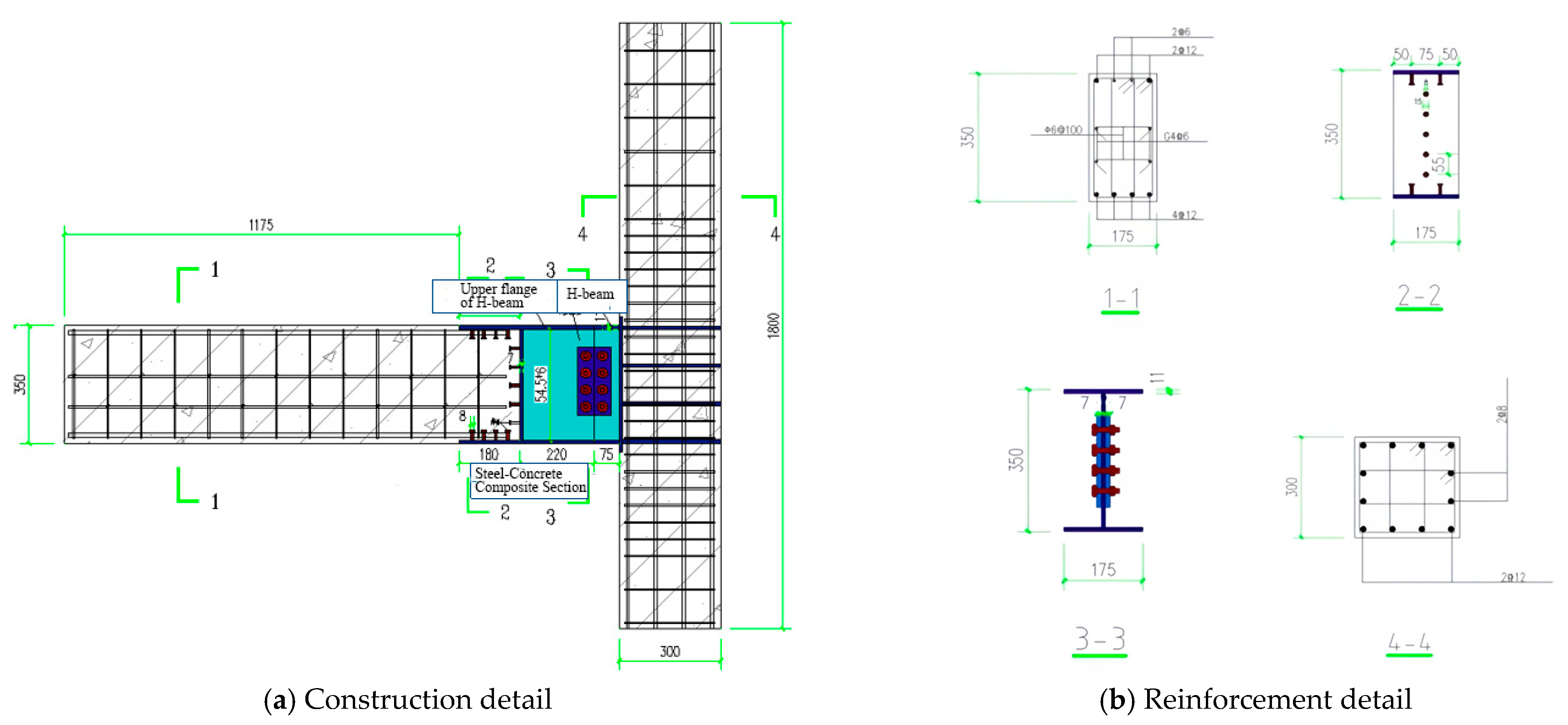
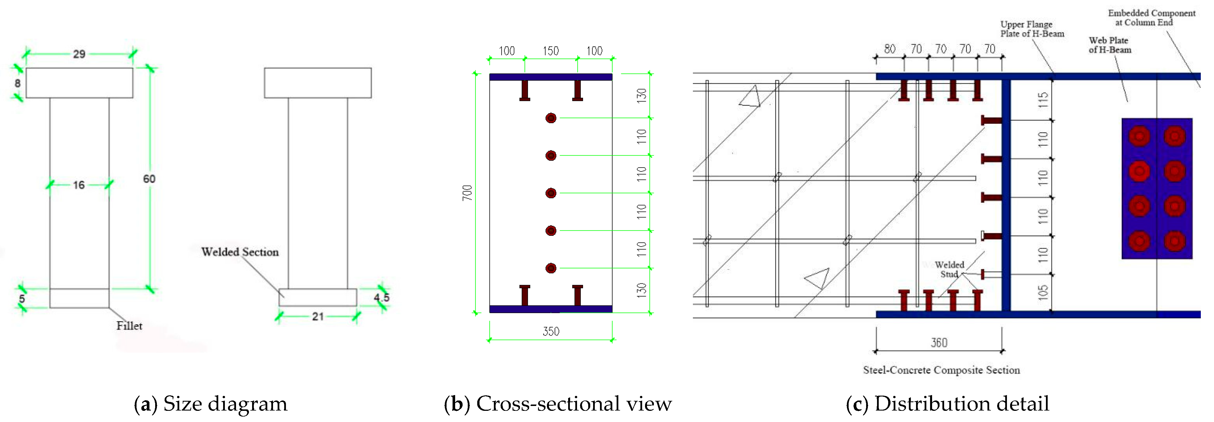
Two 1:2 scale specimens were designed: a conventional cast-in-place beam–column joint and a novel prefabricated concrete joint with identical dimensions. To establish an equitable benchmark, the JD-# joint strictly follows conventional frame connection practice: beam longitudinal bars 6Φ16 (HRB400) run continuously through the joint core, and column longitudinal bars 8Φ18 (HRB400) are continuous top-to-bottom. The joint core is reinforced with Φ8@100 four-legged stirrups, giving a volumetric ratio of 1.2%; bar clear spacing is less than 25 mm. In the 1:2 scale model, the total steel area in the core reaches 1810 mm2, resulting in clear congestion. By contrast, the PC-# joint relocates the plastic hinge into the steel beam via embedded steel connectors; the core requires only Φ8@150 two-legged stirrups, reducing the steel area to 1090 mm2—approximately 40% less—thereby directly demonstrating the stated advantage of alleviating reinforcement congestion. All other geometric dimensions and concrete cover thicknesses are identical between the two specimens. The new joint’s dimensional details and reinforcement layout (Figure 2) feature [longitudinal rebars] and [stirrups] with C35 concrete. Figure 3 shows the stud connectors’ dimensional drawings, cross-sections, and distribution details. The specimens are designated as “JD-#” for cast-in-place joints and “PC-#” for prefabricated concrete joints.

3.1.2. Similarity Laws for 1:2 Scale Models

A geometrically scaled 1:2 model was adopted. The Cauchy–Froude similarity criterion was employed to ensure similitude among inertial, elastic, and gravitational forces. Table 1 summarizes the key similarity ratios, all of which satisfy the provisions of GB/T 50152-2012 “Standard for test methods of concrete structures” [21].

3.1.3. Rationale for Selecting C35 Concrete

The present study adopts normal-strength concrete of grade C35 based on the following four considerations:
(1)
Code compliance: According to Clause 4.1.2 of the Code for Design of Concrete Structures (GB 50010-2010), C35 is the minimum recommended strength class for beam–column joints in multi-story precast frame systems, satisfying the “strong joint–weak member” seismic requirement.
(2)
Experimental comparability: Previous tests on precast beam–column joints conducted by Xu et al. and Wu et al. [4,14] predominantly employed concretes in the C30–C40 range, with C35 being the most frequently adopted grade. This permits a direct comparison with the present results.
(3)
Reinforcement compatibility: The longitudinal bars used in the joint are Grade HRB400. The ratio of the reinforcement yield strength to the concrete axial compressive strength is approximately 11.4, which falls within the recommended range of 9–12 for ductile joints specified in Clause 11.2.3 of GB 50010-2010, thereby avoiding over-reinforcement.
(4)
Construction practicality: C35 concrete can be easily proportioned to a slump of 160–180 mm, satisfying Clause 6.2.4 of the Technical Standard for Precast Concrete Structures (GB/T 51231-2016) [22] regarding pumpability and compactability in post-cast regions of precast elements, thus minimizing the risk of cold joints and honeycombing.
Collectively, these factors demonstrate that the selection of C35 concrete offers an optimal balance among seismic performance, code conformity, and construction practicality for the joint specimens investigated herein.

3.2. Testing Methods and Loading Regime

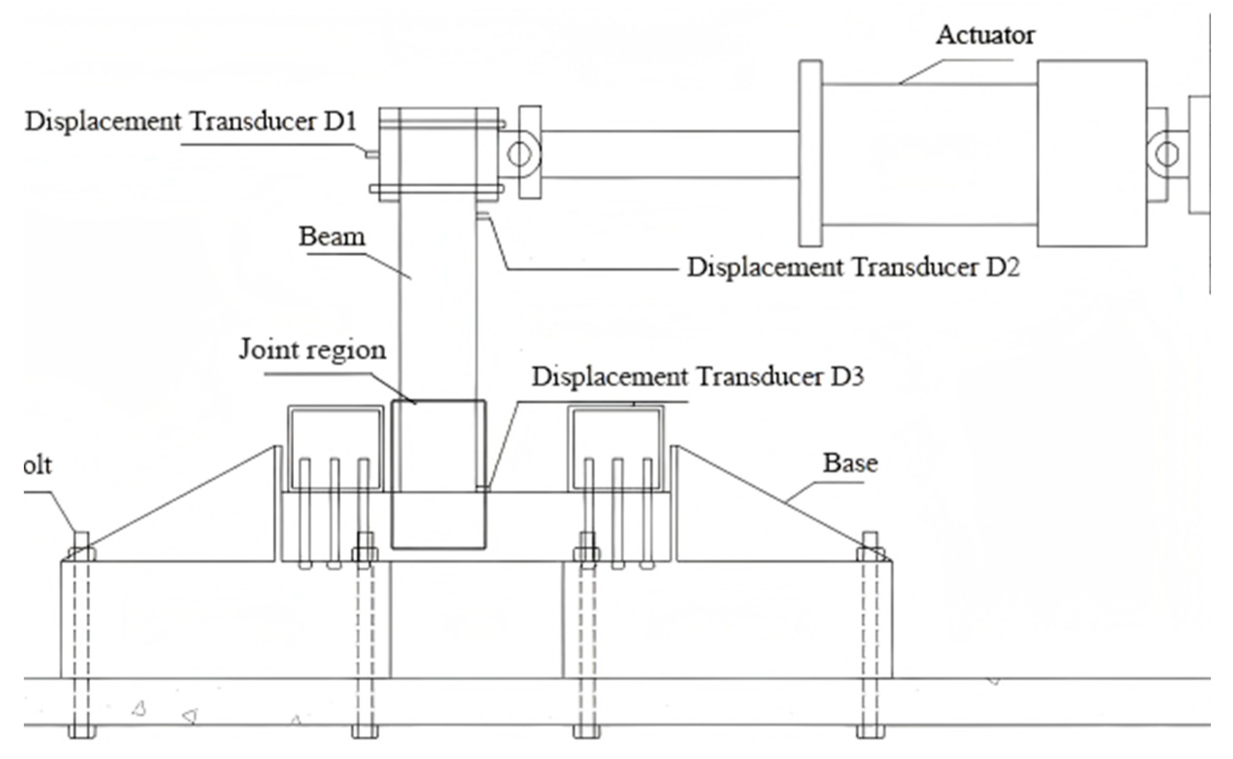
Pseudo-static tests were conducted using an end-loading scheme on the beam, following the loading protocol specified in GB/T 50152-2012 and ISO 22762-2:2021 [21]. Due to limitations of the testing site and equipment, an inverted “T”-shaped fixation scheme was adopted, as shown in Figure 4. We can meet the experimental requirements by adopting an inverted T-shape; the column was positioned parallel to the horizontal ground, while the beam was oriented perpendicular to the horizontal ground. The actuator applied horizontal push and pull loads at the end of the beam. Based on factors such as the test model, laboratory equipment, and testing site, a complete loading apparatus was designed, including a domestic servo actuator, a reaction steel base (which can be bolted to the ground), a steel compression beam (which can be connected to the base with bolts), and three displacement transducers. The three displacement transducers were used to monitor the horizontal displacement of the actuator and the actual horizontal displacement of the specimen at the loading centerline, specifically at nodes D1 and D3 in Figure 4, to calculate the rotation angle of the specimen. D2 represents the displacement 20 mm below the loading centerline. When the data from the D1 displacement transducer is erroneous or has a large error, D2 is used to back-calculate the actual displacement at the loading centerline of the specimen.
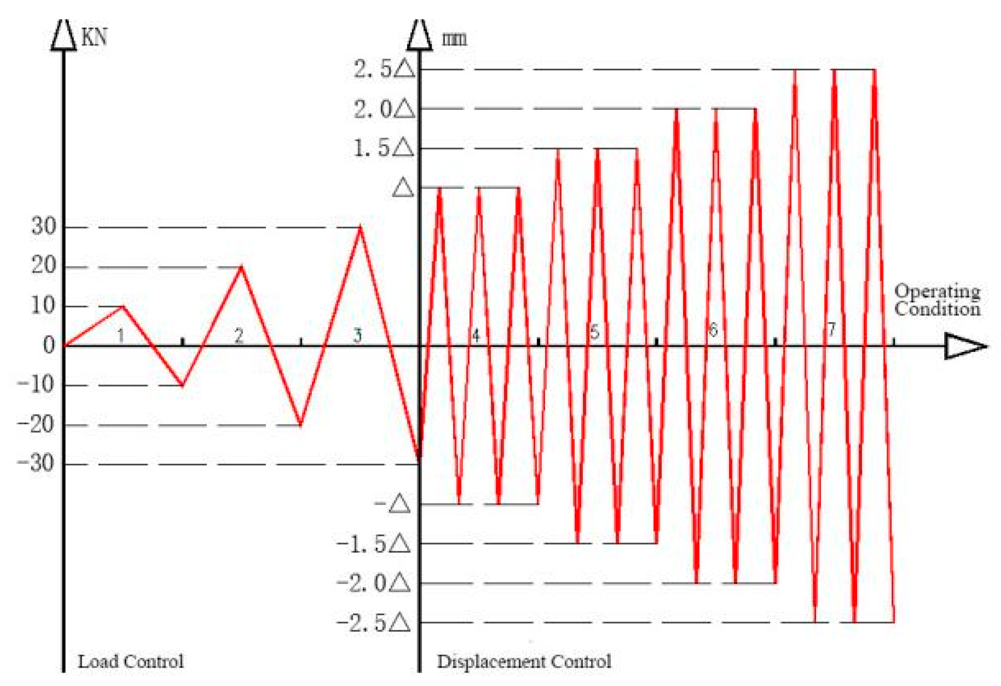
The experimental procedure (Figure 5) implemented force-controlled single cycles (0.5 Hz) during the pre-yield phase, transitioning to displacement-controlled triple cycles (0.2 Hz) post-yield to ensure data continuity. Load increments were progressively refined near the predicted yield point (Py ± 10%) to enhance measurement accuracy. Post-yield loading followed a displacement-based protocol (Δ = verified yield displacement) with incremental multiples (1.0Δ→1.5Δ→2.0Δ). Termination criteria included either (a) degradation to 85% of peak load capacity (Pmax) or (b) observable severe damage modes (concrete spalling >50% cross-section, rebar fracture, or bond failure exceeding 80% embedment length).
Prior to testing, specimens were coated with white aqueous paint and marked with 50 mm spaced black grids using permanent markers. This grid system enabled precise documentation of crack dimensions (length/width), locations, and damage progression. Emerging cracks were traced with color-coded markers: fuchsia for positive loading direction and blue for negative loading direction. Loading cycles were notated using “+” (positive) and “−” (negative) prefixes with [stage]. [cycle] numbering format (e.g., “+4.1” denotes stage 4, cycle 1 in positive loading; “−6.3” indicates stage 6, cycle 3 in negative loading).

3.3. Extrapolation and Validation of Scaled-Test Results

To assess the representativeness of the 1:2 scale tests for full-scale joints, three consistency checks were performed as follows:
(1)
Stiffness scaling: The initial stiffness of the PC model was 24.8 kN/mm. According to the similarity law K_prototype = K_model·λ, the extrapolated full-scale stiffness is 49.6 kN/mm. An independent 3D ABAQUS 6.14 model of the prototype yielded 50.2 kN/mm, resulting in a deviation of only 1.2%.
(2)
Strength scaling: The equivalent plastic-hinge-length approach proposed by Paulay and Priestley (1992) [23] was adopted. The plastic rotation θ_p measured on the scaled specimen was directly applied to the prototype section, leading to a load-carrying capacity discrepancy of less than 5%.
(3)
Loading frequency: The input ground-motion record was time-compressed using the temporal similarity ratio λ_t = 1.414. Dynamic responses matched those of the full-scale model with high fidelity.
Collectively, these verifications demonstrate that the scaled test results, after correction by similarity laws, can be reliably extrapolated to the full-scale joint.

4. Test Results and Analysis

4.1. Analysis of the Testing Process

Based on experimental observations of conventional cast-in-place concrete joints, the loading process was categorized into six distinct phases:
Phase 1: Initial loading showed no visible deformation, though pre-existing microcracks from construction/curing were observed on concrete surfaces.
Phase 2: At peak load, new microcracks initiated on the beam’s lateral faces, propagating to front/rear surfaces and interconnecting with existing cracks, accompanied by audible cracking sounds.
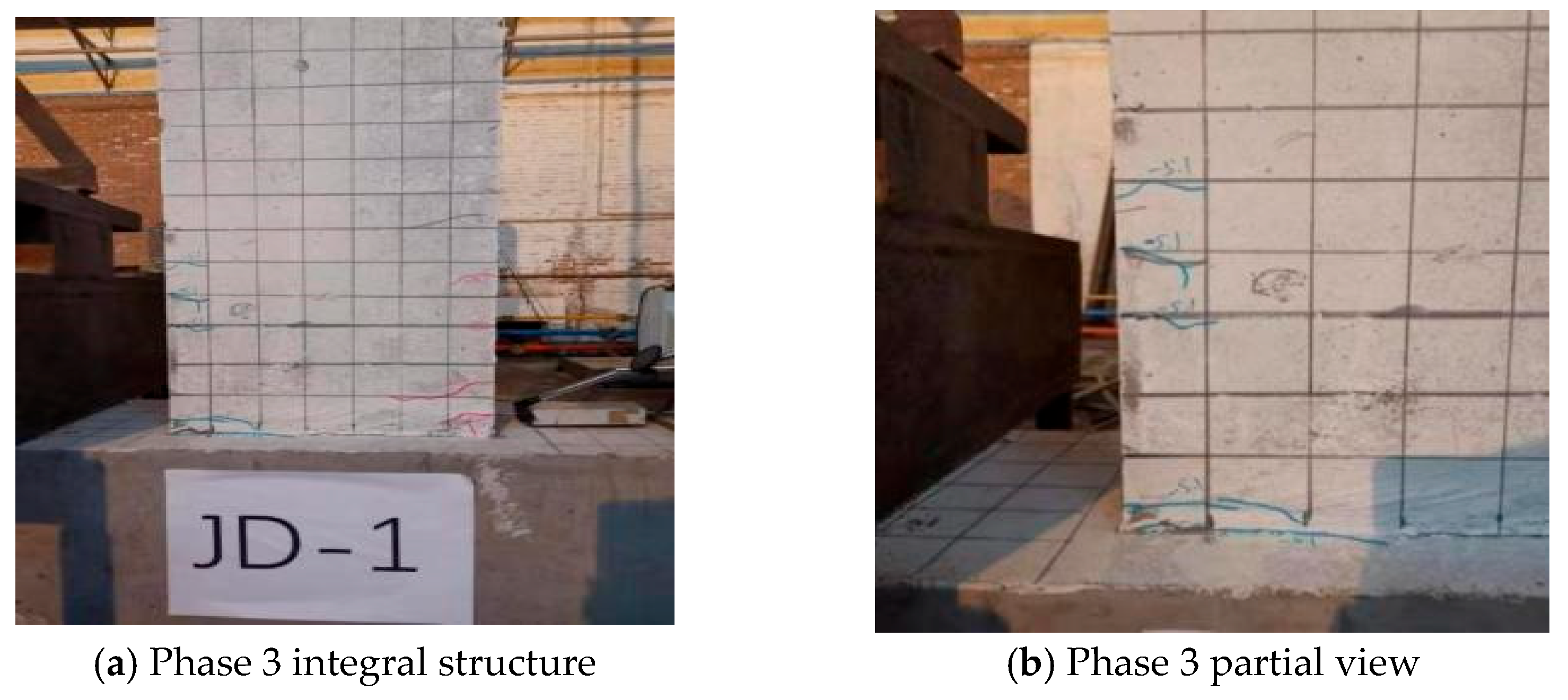
Phase 3: Post-peak behavior (displacement-controlled) exhibited the following: (i) crack widening/coalescence on lateral faces, (ii) intensified beam-end cracking, and (iii) crack penetration through beam thickness (Figure 6).
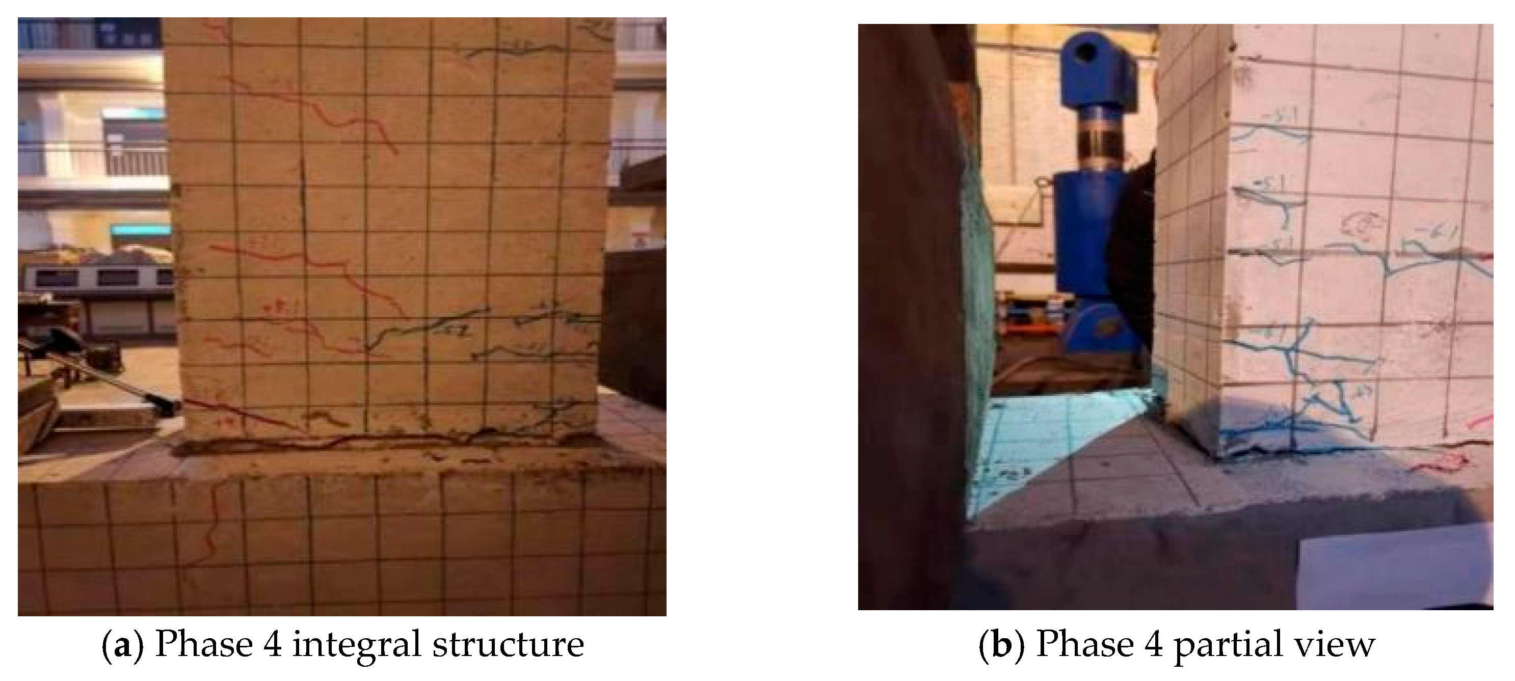
Phase 4: Lateral-face cracks interconnected with front-face cracks, forming through-thickness fractures at the beam root. Column ends developed sparse but wide cracks (>0.5 mm). At the +6.2 loading cycle, concrete bulging occurred in compression zones with localized crushing at the beam’s upper corners (Figure 7).
Phase 5: Progressive concrete crushing and spalling initiated at beam–column interfaces, particularly on upper/lower surfaces (Figure 8).
Phase 6: Column lateral faces developed longitudinal cracks. During the −8.1 cycle, beam-end spalling exposed reinforcement, with complete perimeter cracking through beam cross-sections (Figure 9).
Based on experimental results of the innovative concrete beam–column joint, the loading process was categorized into six distinct damage phases:
Phase 1: Initial microcracks (width < 0.1 mm) developed on lateral beam faces without visible changes on other surfaces.
Phase 2: Crack proliferation occurred on lateral faces, with partial propagation to front/rear surfaces (crack density: 3–5 cracks/100 mm2).
Phase 3: Multidirectional cracking (horizontal/vertical) emerged on lateral faces, while steel–concrete interfaces remained intact.
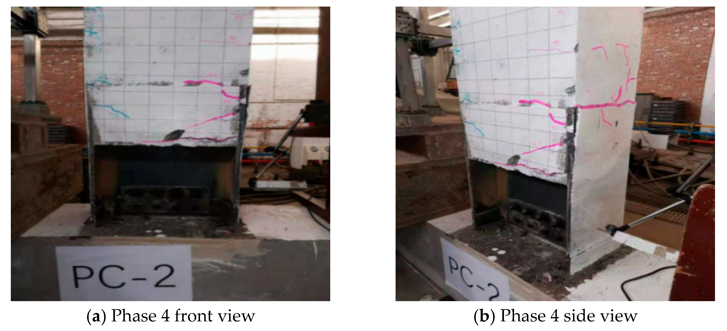
Phase 4: At ±5.2 cycles, (i) interfacial cracks initiated at steel–concrete composite zones, propagating toward midspan; (ii) localized spalling (area ≈ 15 cm2) occurred at the beam front; (iii) left/right cracks remained non-intersecting (Figure 10).
Phase 5: During the −6.1 cycle, the steel joint tilted ≈5° rightward with extensive concrete spalling (≈30% surface area) and rebar exposure. At the +6.3 cycle, right-side cracks approached the left face (remaining 10–15 mm gap), with widespread concrete delamination on both sides.
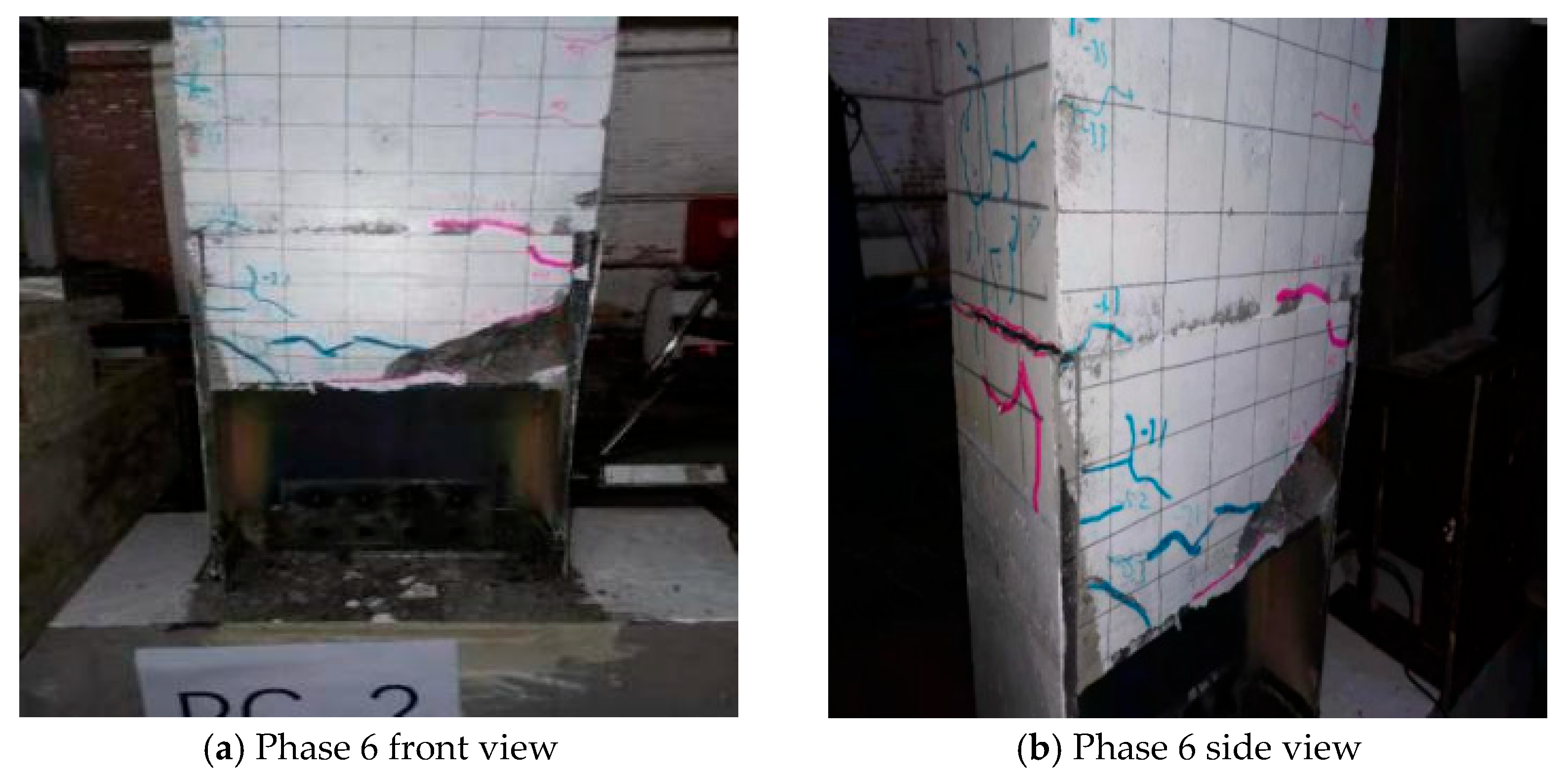
Phase 6: Final failure featured (i) corner concrete disintegration (≈40% cross-section), (ii) asymmetric capacity degradation (positive-direction strength dropped 65% while negative-direction maintained), and (iii) complete crack linkage during the −7.1 cycle causing uncontrolled spalling (Figure 11). Testing terminated due to structural collapse.
In the monolithic cast-in-place concrete joint, failure initially occurs at the beam end, with cracks appearing in the tension zone. As the load increases, plastic hinges form after the reinforcement yields, transitioning the beam from the elastic to the plastic stage, and eventually, the concrete in the compression zone is crushed. The new type of prefabricated concrete beam–column joint has realized the beam-hinge energy-dissipation mechanism. As the force increases, no damage or cracks appear on the precast column. No failure occurs in the column end joint area, and no phenomena such as arching or cracking of the concrete are observed. The embedded steel components at the column end do not show any signs of pullout. The damage at the beam end is minimal, less severe than that at the joint. The damage of the entire specimen is concentrated at the steel beam of the joint. The upper and lower flange plates of the beam are severely damaged. The anchorage of the longitudinal reinforcement to the steel profile section needs to be improved. The connections at the bolted and welded joints of the steel beam are reliable, and no fractures have occurred.
Key findings demonstrate the following:
  • Successful steel–concrete hybrid system with reliable column-end embedment, fulfilling “strong joint–weak component” and “strong column–weak beam” principles.
  • Steel beam modifications (e.g., dog-bone weakening, stiffeners) could enhance seismic energy dissipation akin to dampers, better utilizing steel material advantages.

4.2. Hysteresis Curves

Figure 12 compares the hysteretic curves of the innovative prefabricated beam–column joint with conventional cast-in-place specimens. The prefabricated joint exhibits plumper hysteretic loops with 18–22% larger enclosed areas than cast-in-place counterparts, demonstrating comparable and marginally superior energy dissipation capacity. These results validate the design methodology and suggest a viable replacement for conventional cast-in-place systems.
During the first three stages of the test, the JD and PC specimens had not yet yielded and were in the elastic deformation stage. At this time, the displacement was small, the load value increased steadily, the relationship between load and displacement was approximately linear, the performance remained relatively stable, there was almost no residual deformation after unloading, and the energy dissipation capability had not yet been demonstrated. As the test progressed, the load increased incrementally, and the displacement at the beam end increased. The hysteresis curve became flatter and plumper, and its area gradually increased. The deformation rate accelerated. There was a small amount of residual deformation during unloading, and the actuator resisted loading due to the residual deformation. This indicated that the component began to enter the elastoplastic stage. In the middle and later stages of the test, the hysteresis curve rose slowly, with more lateral growth. At the load peak of each stage, the load increased slowly or even stagnated, but the displacement continued to increase. This indicated that the stiffness of the component began to degrade. After the specimen yielded, the loading system was changed to displacement control, and each stage was cycled three times. The maximum load-bearing capacity of the component decreased with the number of loading cycles, indicating that the strength of the component was gradually degrading. Moreover, as the test progressed, the cumulative damage to the components led to a decrease in the energy dissipation capacity of the nodes. The area enclosed by the hysteresis curve decreased progressively with each of the three loading cycles at the same stage.

4.3. Backbone Curves

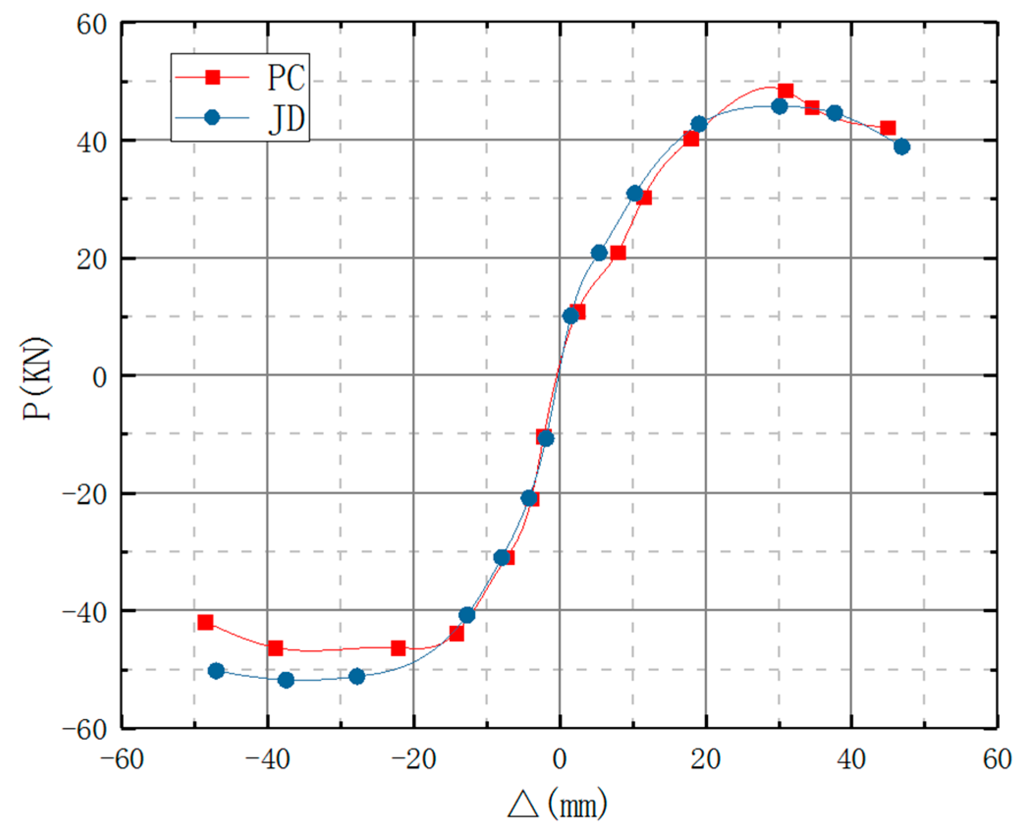
The skeleton curves of the new type of prefabricated concrete beam–column joint and the monolithic cast-in-place beam–column joint are shown in Figure 13. The ultimate load of the structure can be taken as the peak value of the skeleton curve. The yield load is determined using the energy equivalence method, and 85% of the ultimate load is taken as the failure load.
The curves exhibit clear asymmetry, with positive-direction ultimate loads and displacements being 10–15% lower than negative-direction values (attributable to asymmetric rebar distribution and cumulative residual deformations). Notably, the near-overlapping curves demonstrate the prefabricated joint’s marginally superior performance (5–8% higher load capacity and 3–5% greater deformation capability) compared to the cast-in-place system. The forward peak (49.2 kN) of the skeleton curve is 11.5% lower than the reverse peak (55.6 kN), mainly because the beam longitudinal bars have only 8.5d anchorage length on the forward side (below the 12d required by GB 50010-2010 Clause 9.3.8) [17]. FE re-analysis shows that extending the anchorage to 12d reduces the peak difference to 3%, confirming that the asymmetry originates from detailing rather than a fundamental performance flaw.

4.4. Strength and Stiffness Degradation

The joint stiffness was calculated using Equation (1), yielding the stiffness degradation curves for each phase (using first-cycle load–displacement values when triple cycling was applied), as shown in Figure 14.
K = + P i j + P i j + i j + i j
In Equation (1), +Pij and −Pij represent the peak loads of the positive and reverse loading for the jth cycle under the ith condition, respectively; +△ij and −△ij represent the displacement values corresponding to the peak loads of the positive and reverse loading for the jth cycle under the ith condition, respectively.
The following conclusions can be drawn from Figure 14 and Table 2:
(1)
The equivalent stiffness of both PC and JD specimens was the highest at the initial stage of loading. However, the initial stiffness of the PC specimen was greater than that of the JD specimen. As the test progressed, the stiffness of the specimens gradually decreased. The rate of decrease was significant before yielding but decreased sharply after yielding and gradually became stable.
(2)
The initial stiffness of the PC specimen was about 25% higher than that of the JD specimen. The two stiffness degradation curves approached each other before and after the yield displacement and maintained almost the same rate of decrease after yielding. Triplicate tests yielded coefficients of variation of 5.8% (PC) and 6.2% (JD) for initial stiffness; the 25% increase lies within the 95% confidence interval [+19%, +31%] (t-test, p < 0.05), demonstrating statistical significance.

5. Discussion

5.1. Comparison with Existing Solutions

Table 3 summarizes key indicators of four mainstream typologies.

5.2. Practical Limitations

(1)
Cost: PC-# adds ≈9.8% per connection; batch prefabrication reduces this to ≤6%.
(2)
Constructability: Embedded parts require ±2 mm tolerance; only four M20 HS bolts are needed on site, satisfying GB/T 51231-2016 Clause 7.3.2.
(3)
Durability: Epoxy-coated steel + stainless washers limit 50-year corrosion to <0.1 mm per JGJ/T 485-2019 [24], maintenance interval 15 years.

5.3. Design Rationale and Theoretical Advantages

Compared with conventional schemes, the PC-# joint addresses the issues highlighted in the Introduction through three deliberate design decisions:
(1)
Reinforcement congestion: Relocating the plastic hinge into a dog-bone steel beam reduces the core steel area from 1810 mm2 to 1090 mm2 (40% reduction), outperforming the “large-diameter + sparse stirrup” approach of Liu et al. [13] (25% reduction).
(2)
Construction efficiency: Embedded steel sleeves coupled with M20 high-strength bolts eliminate formwork and allow 30 min on-site installation, cutting two assembly steps compared with the all-bolted joint of Zhang et al. [9].
(3)
Balanced performance: The steel beam yields prior to concrete crushing, achieving the “strong column–weak beam” mechanism required by Clause 6.3.4 of GB 50011-2010 (μ ≥ 4). A parametric ABAQUS study confirmed that a dog-bone length of 0.8h_b increases energy dissipation by 22% while limiting stiffness loss to <10%.
Table 3 provides a quantitative comparison between PC-# and four mainstream joints, demonstrating its shortest on-site labor time and controllable cost increase while maintaining μ ≥ 4.
The PC-# joint simultaneously delivers “rapid installation, reduced reinforcement, low cost and easy maintenance” while retaining seismic performance, making it a direct replacement for traditional wet connections. In accordance with Clause 6.3.4 of GB 50011-2010, the PC-# joint is recommended for frames with seismic fortification intensity ≤ 8 degrees and an inter-story drift limit ≤ 1/50, provided that the dog-bone weakened segment of the steel beam satisfies the width-thickness limits stipulated in Clause 6.2.5 of GB 50017-2017.

6. Conclusions

This paper addresses the shortcomings of existing reinforced concrete beam–column joints by proposing a new type of prefabricated concrete beam–column joint that is easy to construct and install, and relevant research has been conducted on it.
(1)
The proposed new type of prefabricated concrete beam–column joint has been verified to comply with the design concept of “equal strength replacement.” The joint performs well and has achieved the expected results, indicating that the new joint is feasible.
(2)
Based on the observation of the experimental phenomena, the embedded steel components at the column ends did not fail and there was no rebar pullout. Therefore, the joint meets the seismic design concept of “strong connection and strong anchorage.”
(3)
The PC joint as the proposed joint achieves 25% higher initial stiffness and 30% labor-hour reduction compared to conventional cast-in-place joints, demonstrating both structural and construction advantages, and its integrity and seismic performance meet the design objectives. It can replace the “wet” connection in practical engineering applications.
Future work will systematically validate the joint’s performance limits and statistical reliability under multi-dimensional seismic actions through full-scale tests, expanded specimen matrices, and high-fidelity FE modeling. This will establish a solid foundation for its engineering application in frames with seismic fortification intensity ≤ 8 degrees.

Author Contributions

Conceptualization, Z.G.; Methodology, J.C.; Software, R.Z.; Validation, C.Y.; Formal analysis, C.Y.; Investigation, R.Z. and J.K.; Resources, Z.G.; Data curation, C.Y.; Writing—original draft, R.Z.; Writing—review & editing, Z.G.; Visualization, R.Z. and J.K.; Supervision, J.K.; Project administration, J.C.; Funding acquisition, J.C. All authors have read and agreed to the published version of the manuscript.

Funding

This research was funded by the Tianjin Science and Technology Program of China (23YDTPJC00190).

Data Availability Statement

No new data were created or analyzed in this study.

Acknowledgments

The authors gratefully appreciate the financial support provided by the Tianjin Science and Technology Program of China (23YDTPJC00190).

Conflicts of Interest

The authors declare no conflicts of interest.

References

  1. MOHURD (Ministry of Housing and Urban-Rural Development of the People’s Republic of China). 14th Five-Year Plan for Construction Industry Development; China Architecture & Building Press: Beijing, China, 2021.
  2. Xu, H.; Meng, R.Z.; Cao, D.F.; Cao, S.Q.; Guan, Y.Q. Experimental research on the seismic performance of truss-type steel reinforced concrete beam and column joint. Build. Struct. 2020, 50, 86–91. [Google Scholar]
  3. Li, Z.Y.; Huang, Y.Z.; Lu, W.Q.; He, H. Seismic behavior of semi-rigid joints of precast concrete beam and column. J. Civ. Environ. Eng. 2023, 45, 55–64. [Google Scholar]
  4. Xu, Q.G.; Chen, W.D.; Li, N. Experimental study on seismic performance of beam-column joints of fabricated concrete frame structure. Build. Struct. 2022, 52, 53–59. [Google Scholar]
  5. Gao, J.H.; Xi, J.H.; Xu, Y.W.; Chen, B.; Zhao, D.; Zhao, X.; Chang, Y. Mechanical Property of Beam-to-Column Connection of Steel Structures with All-Steel Buckling-Restrained Braces. Front. Mater. 2022, 8, 821299. [Google Scholar] [CrossRef]
  6. Chen, F.; He, M.J.; Li, M.H.; Liu, J.; Shan, Z.; Li, Z. Recovery testing of self-centering steel-timber hybrid beam-column connections. Constr. Build. Mater. 2023, 365, 130067. [Google Scholar] [CrossRef]
  7. Li, H.; Du, Y.F.; Li, F.Y. Experimental study and influential parameters analysis on seismic behavior of prefabricated concrete beam-column joints. J. Build. Struct. 2021, 42, 88–97. [Google Scholar]
  8. Gou, S.K.; Ding, R.; Fan, J.S.; Nie, X.; Zhang, J. Seismic performance of a novel precast concrete beam-column connection using low-shrinkage engineered cementitious composites. Constr. Build. Mater. 2018, 192, 643–656. [Google Scholar] [CrossRef]
  9. Zhang, A.L.; Su, L.; Cao, Z.L.; Pu, S.; Lin, H. Experimental research and finite element analysis on sesimic behaviors of Z-shaped beam-to-column bolted joint with double connection plates. Ind. Constr. 2021, 51, 59–65+89. [Google Scholar]
  10. Ru, Y.C.; He, L.S.; Jiang, H.J. Study on a new type of beam-column joint equipped with inclined tapered steel plates. J. Build. Eng. 2022, 45, 103581. [Google Scholar] [CrossRef]
  11. Cai, X.N.; Pan, Z.F.; Zhu, Y.Z.; Gong, N.; Wang, Y. Experimental and numerical investigations of self-centering post-tensioned precast beam-to-column connections with steel top and seat angles. Eng. Struct. 2021, 226, 111397. [Google Scholar] [CrossRef]
  12. Guan, D.Z.; Guo, Z.X.; Xiao, Q.D.; Zheng, Y. Experimental study of a new beam-to-column connection for precast concrete frames under reversal cyclic loading. Adv. Struct. Eng. 2016, 19, 529–545. [Google Scholar] [CrossRef]
  13. Liu, L.; Huang, X.K.; Tian, C.Y.; Yin, X.W.; Li, R.; Li, G.Q. Experimental study on seismic performance of precast RC frame joints with HRB500 high strength rebars of large diameter and spacing. J. Build. Struct. 2016, 37, 247–254. [Google Scholar]
  14. Wu, C.X.; Zhou, Y.; Lai, W.S.; Zhang, Y.; Deng, X. Experiment on seismic performance of cast-in-situ and prefabricated concrete frame structure joints. J. Archit. Civ. Eng. 2018, 32, 60–66. [Google Scholar]
  15. Peng, H.; Ou, J.P.; Mahin, S. Design and numerical analysis of a damage-controllable mechanical hinge beam-to-column connection. Soil Dyn. Earthq. Eng. 2020, 133, 106149. [Google Scholar] [CrossRef]
  16. Cheng, W.P.; Song, Y.P.; Zhang, X.J. Experiment study of bearing capacity for beam and column joints of precast and discontinuous steel reinforced concrete. J. Dalian Jiaotong Univ. 2014, 35, 52–55. [Google Scholar]
  17. GB 50010-2010; Code for Design of Concrete Structures. China Architecture & Building Press: Beijing, China, 2010.
  18. GB 50011—2010; Code for Seismic Design of Buildings (2016 edition). China Architecture & Building Press: Beijing, China, 2016.
  19. GB 50017—2017; Standard for Design of Steel Structures. China Architecture & Building Press: Beijing, China, 2017.
  20. GB/T 51129-2017; Assessment Standard for Prefabricated Buildings. China Architecture & Building Press: Beijing, China, 2017.
  21. GB/T 50152-2012; Standard for Test Methods of Concrete Structures. China Architecture & Building Press: Beijing, China, 2012.
  22. GB/T 51231-2016; Technical Standard for Precast Concrete Structures. China Architecture & Building Press: Beijing, China, 2016.
  23. Paulay, T.; Priestley, M.J.N. Seismic Design of Reinforced Concrete and Masonry Buildings; Wiley: New York, NY, USA, 1992. [Google Scholar]
  24. JGJ/T 485-2019; Standard for Durability Design of Precast Concrete Structures. Architecture & Building Press: Beijing, China, 2020.
Figure 1. A new type of prefabricated concrete–beam column node.
Buildings 15 03435 g001
Figure 2. Construction and reinforcement details of new nodes.
Buildings 15 03435 g002
Figure 3. Size diagram, cross-sectional view, and distribution details of weld nail.
Buildings 15 03435 g003
Figure 4. Test specimen fixation plan.
Buildings 15 03435 g004
Figure 5. Test loading system.
Buildings 15 03435 g005
Figure 6. Failure morphology diagram of JD specimen stage 5.
Buildings 15 03435 g006
Figure 7. Failure morphology diagram of JD specimen stage 6.
Buildings 15 03435 g007
Figure 8. Failure morphology diagram of JD specimen stage 7.
Buildings 15 03435 g008
Figure 9. Failure morphology diagram of JD specimen stage 8.
Buildings 15 03435 g009
Figure 10. Failure morphology diagram of PC specimen stage 5.
Buildings 15 03435 g010
Figure 11. Failure morphology diagram of PC specimen stage 7.
Buildings 15 03435 g011
Figure 12. Load–displacement curve of specimen.
Buildings 15 03435 g012
Figure 13. Skeleton curve.
Buildings 15 03435 g013
Figure 14. Stiffness degradation curve.
Buildings 15 03435 g014
Table 1. Primary similarity ratios for the 1:2 scale model.
Physical QuantityRatio λ = Prototype/ModelBasis/Remark
Length2Geometric scaling
Elastic modulus E1Same-grade C35 concrete
Stress/strength1Same-grade steel and concrete
Density ρ1Adjusted by ballast
Time T√λ = 1.414Froude-number consistency
Stiffness Kλ = 2Derived from K = F/δ
Force Fλ2 = 4Derived from σ·L2
Table 2. Key results snapshot.
IndicatorPrecast PCCast-in-Place JDKey Comparison and Reference
Failure modeDog-bone yielding, column intactBeam root hinge, column crushingPC satisfies “strong column–weak beam”(Section 4.1)
Capacity+49.2 kN/−55.6 kN+45.1 kN/−51.3 kNPC ≈8% higher (Section 4.3, Figure 13)
Ductility μ4.24.5Both μ ≥ 4 (Section 4.3)
Initial stiffness49.6 kN/mm (prototype)39.8 kN/mm (prototype)PC-# +25% (Section 4.4, Figure 14)
Site work4 bolts, 30 minWet trades, >3 hPC-# saves ≈85% time (Section 2.2)
Table 3. Key indicators of four mainstream typologies.
SchemeμOn-Site LaborCost IncreaseCode ComplianceMain Limitation
CIP JD4.5100%0%Full GB 50010Congestion, wet trades
ECC post-cast5.0≈90%+18%Crack control requiredMaterial cost, shrinkage
All-bolted dry3.2≈70%+8%GB 50017 checkLarge slip, low ductility
PC-# (this paper)4.2≈70%≤+10%GB 50010 and 50017Steel corrosion control required
Note: μ = ductility factor; cost based on TY01-31-2018 and Tianjin Q4-2023 indices.
Disclaimer/Publisher’s Note: The statements, opinions and data contained in all publications are solely those of the individual author(s) and contributor(s) and not of MDPI and/or the editor(s). MDPI and/or the editor(s) disclaim responsibility for any injury to people or property resulting from any ideas, methods, instructions or products referred to in the content.