Abstract
Currently, the global construction industry is facing challenges of stagnant efficiency and cost overruns. The potential of modular construction has not been fully unleashed due to the disconnection between design and manufacturing. This paper proposes a P-DFMA (Platform-Design for Manufacture and Assembly) building product platform architecture for modular apartments. The research establishes a three-level standardization framework of “modular unit-component-connector”, covering core residential modules, light steel keel systems, and high-strength bolt joints. Finite element simulation using SimSolid is employed to ensure manufacturing feasibility, and a standardized component library and a full-process collaborative P-DFMA architecture for modular apartments are developed. Verified through the case of the modular dormitory building project at Tianjin Chengjian University, the results show that compared with the traditional prefabricated construction mode, the P-DFMA platform mode achieves a cost savings rate of 54.8% in project design, production, and cross-link collaboration. This proves the feasibility and architectural advantages of the platform in improving the full-process efficiency and optimizing costs of modular buildings.
1. Introduction
The global construction industry currently faces a contradiction between scale expansion and stagnant efficiency. Over the past two decades, its average annual production growth rate has been only 1%, far lower than the 3.6% of the manufacturing industry and the 2.8% average of the global economy [1]. Against the backdrop of rising labor costs, skill shortages, and pressure from carbon emission control, the industry is in urgent need of transformation towards industrialized construction. Modular construction, as a core carrier, has demonstrated significant advantages. For example, the UK has shortened the on-site construction cycle by 40% through platform-based design, and Singapore’s public housing projects have improved production efficiency by 40% [2,3].
However, the potential of modular construction has not been fully tapped. Academic research mostly focuses on optimizing individual links and lacks a full life cycle perspective. For instance, the application of BIM technology is limited to the design stage, and research on component standardization fails to address interface compatibility issues [4,5]. In industrial practice, the disconnection between design and manufacturing phases leads to over 60% of precast concrete components requiring on-site secondary processing, a high rework rate in the steel structure supply chain, and the lack of interface standardization resulting in an average cost overrun of 15–20% in global modular projects [5,6,7]. The Design for Manufacture and Assembly (DFMA) concept has achieved remarkable results in the manufacturing industry, reducing the number of parts by 51% and shortening assembly time by 62% [8]. When applied to the construction industry, it is necessary to balance the diversity of modules and manufacturing standardization. Existing research has not formed a platform architecture that takes into account full-process collaboration, and the application of DFMA remains at the theoretical level.
To address this, this paper establishes a P-DFMA technology system for modular apartment buildings. These buildings have fixed core functional layouts and high repetition rates of the same unit types, which align with the P-DFMA concept. The specific objectives include the following: constructing a three-level standardization framework of “modular unit-component-connector”, systematically defining the reuse rules and interface constraints of core residential modules, light steel keel load-bearing systems, and high-strength bolt connection joints to solve the problems of fragmentation and poor compatibility in existing standardization research; verifying the mechanical properties of key joints through SimSolid finite element simulation, establishing a closed-loop mechanism for design, simulation, and optimization to fill the academic gap in digital verification of manufacturing feasibility; developing a standardized component library suitable for apartment buildings, integrating and storing the basic attributes, technical parameters, production information, and association rules of components to provide reusable data support for modular design; researching and developing a “front-end-middle-end-back-end” full-process collaborative architecture, breaking the limitation of data fragmentation in traditional platforms, establishing a closed-loop of design and production data flow, and improving the theoretical system of building product platforms. The cost savings rate in project design, production, and cross-link collaboration reaches 54.8%, providing support for the large-scale promotion of industrialized construction. Additionally, this technology system can adapt to other building types, such as hospitals and commercial facilities, by adding special modules and constraint rules, providing a flexible technical tool for the industrial transformation of the industry.
2. Literature Review
2.1. Product Platform
The concept of product platform originated in the manufacturing industry. Its core definition is “a set of shared design and technical elements that can derive a variety of products” [9], and its essence is to support the development of serialized products through shared core technologies and standardized frameworks [10]. In the field of product platforms, the search scope covers three major databases: Web of Science Core Collection, Scopus, and CNKI (China National Knowledge Infrastructure), with literature limited to the period 2021–2025. Effective literature (823 articles) was obtained through subject term combination search. The screening criteria were a frequency of ≥15 times and direct relevance to platform-based design, component standardization, and manufacturing collaboration, initially resulting in 32 candidate keywords. Using the cosine similarity algorithm (cluster resolution 0.7) of VOSviewer 1.6.20 software for clustering, three core clusters were generated. After verification by two experts with more than 10 years of research experience in modular construction, terms with weak correlation were excluded, and finally 28 core analysis keywords were determined (Figure 1). With “platform”, “product”, and “construction” as core nodes, it presents the research ecosystem in the interdisciplinary field of architecture and manufacturing. The red cluster focuses on “platform”, “construction”, and “component”, associated with practices such as construction industrialization and prefabricated components; the green cluster centers on “integration”, “industry”, and “digital twin”, reflecting the penetration of digital technology into the industry; and the blue cluster involves “system”, “productivity”, and “planning”, pointing to systematic management and efficiency improvement. The dense connections between clusters reflect the trend of in-depth integration of platformization, digitalization, and manufacturing technology in the process of construction industrialization and also reveal the industry’s research path of exploring “technology integration-efficiency improvement-system reconstruction”, providing visual support for this paper to sort out the technical collaboration logic in the field of building manufacturing and explore innovative directions.

Figure 1.
Keyword co-occurrence map in the product platform field in the recent three years.
To verify the feasibility of the building product platform, BIM can be used to build a parametric model of core components, and material performance data and manufacturing constraints can be embedded simultaneously. Then, finite element software is used to model and analyze key components. Load types should fully cover static, wind, seismic, and dynamic working conditions: static working conditions include component self-weight and floor live load; wind working conditions determine parameters with reference to the basic wind pressure at the project location; seismic working conditions set analysis conditions according to the site fortification intensity; and dynamic working conditions consider hoisting impact and equipment vibration. Through multi-condition verification, potential risks in structural safety and manufacturing links can be identified in advance, providing data support for the optimization and improvement of the building product platform.
In manufacturing, platform strategies have become industry standards. Toyota’s TNGA (Toyota New Global Architecture) platform [11] achieved a 70% increase in parts commonality and a 30% reduction in new car development cycles by sharing core modules such as chassis and powertrains. General Motors Company (GM)’s global platform strategy further realized cross-brand resource integration; its Delta platform [12] supported the development of compact cars for multiple brands such as Chevrolet and Buick, reducing manufacturing costs by 25%. Apple Inc.’s iOS ecosystem [13] supports multi-terminal collaboration, such as iPhone and iPad, through a unified application programming interface (API), with over 2 million applications created by third-party developers based on this platform, forming a huge product ecosystem. Quantitative studies on platform benefits show that manufacturing enterprises adopting product platforms achieve, on average, a 20–40% reduction in new product development cycles, a 30–50% increase in parts reuse rates, and a 15–25% reduction in production complexity [14]. This efficiency improvement has promoted the expansion of platform concepts from traditional manufacturing to complex product fields, providing methodological references for platformization exploration in the construction industry.
2.2. Design for Manufacture and Assembly (DFMA)
The concept of DFMA is rooted in the DFX (Design for X) set [15], with its core components being Design for Manufacture (DFM) and Design for Assembly (DFA) [16]. As the foundation of DFA, DFM focuses on optimizing product manufacturability; the DFMA principles formed by their integration require product development teams to simultaneously consider manufacturability and assemblability throughout the design process. The goal is to improve efficiency by designing multi-functional and easy-to-manufacture components, reducing the use of fasteners, and minimizing unnecessary adjustments [17,18,19]. The DFMA concept originated in the mid-1980s, initially emerging as a business strategy to enhance enterprise market competitiveness, preceding the implementation of full-quality ISO standardization [20]. In manufacturing, Boothroyd and Dewhurst (1982) first defined DFMA through quantitative tools, clearly identifying it as a methodology “supporting serialized product development through shared core technologies and standardized architectures”, with the core being evaluating the manufacturing feasibility and assembly efficiency of design schemes [21].
In the field of DFMA, the Engineering Village database was supplemented, and 517 valid studies were obtained through retrieval. First, synonymous terms such as “building assembly” and “construction assembly” were merged, and then 25 candidate keywords were selected according to the criteria of frequency ≥12 times and thematic relevance. Using the cosine similarity algorithm for clustering, four core clusters were generated. After joint verification by one DFMA expert in the manufacturing industry and one building structure expert, 23 core keywords were retained (Figure 2). With “dfma” as the core node, it connects research directions in multiple fields. The red cluster focuses on manufacturing, assembly processes, and efficiency, which is the traditional application scenario of DFMA; the green cluster is associated with materials and recycling, reflecting its expansion to the field of sustainability; the blue cluster involves systems and integration, reflecting research on digital technology and cross-link collaboration; and scattered nodes such as the yellow cluster supplement subdivided directions. From the perspective of cluster correlation, the strengthened connection between traditional manufacturing (red), material sustainability (green), and digital collaboration (blue) indicates that DFMA is diverging from a single field to multiple fields, showing a trend of integrated development.
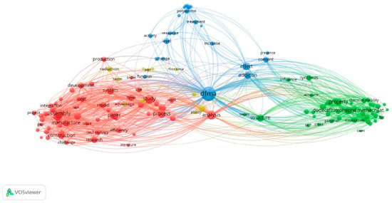
Figure 2.
Keyword co-occurrence network map of DFMA in the recent three years.
The development of digital manufacturing technologies has promoted the upgrading of DFMA towards precision and collaboration. Research by Wen pointed out that reducing module size errors from ±5 mm to ±2 mm through tolerance control models reduced on-site adjustment work by 80% [22]; British scholar Gibb proposed adding an “on-site assembly sequence planning” module for construction scenarios, and his team verified this method in the London Olympic Village project, increasing on-site assembly efficiency by 35% [23]. Currently, multiple tools supporting DFMA implementation have emerged in the market, such as 3D EXPERIENCE-PLM®, ARAS Soft®, and SIEMENS Teamcenter®PLM. These tools help product development teams practice DFMA principles in design and manufacturing links by providing calculation support and process design flexibility [24,25,26,27]. However, the industry still faces three major bottlenecks: first, the lack of dedicated DFMA tools for specific building types, making it difficult to balance product diversity and standardization; second, 70% of manufacturing feasibility evaluations rely on experience judgment, with insufficient digital support; and third, there are barriers to cross-link knowledge transfer, and full-process collaboration efficiency needs improvement.
2.3. P-DFMA (Platform-Design for Manufacture and Assembly)
P-DFMA (Platform-Design for Manufacture and Assembly) refers to platform-based design for manufacture and assembly [28,29]. It is a product development concept that combines platform-based thinking with DFMA methods. Published by the Royal Institute of British Architects (RIBA) in 2021, P-DFMA is defined as “the process by which designers develop and utilize platform construction systems to create new customized construction assets” [30]. Such platforms take digital technology as the core driving force, deeply integrate various links such as architectural design, component manufacturing, and on-site construction, and build an efficient collaborative and data-sharing ecosystem. The design principle of P-DFMA is “Design to Value” [31], which requires that the manufacturability and assemblability value of a product be considered simultaneously in the initial stage of product design to ensure that the design does not increase the product production cost or reduce production efficiency.Existing platforms have many limitations in dimensions such as objectives, methods, and scope, and the specific problems and manifestations can be further clarified with reference to (Table 1).
2.3.1. Objective Level
Existing modular building product platforms have significant limitations in objective setting, with the core manifestations being a tendency towards singularity and the lack of a full-life-cycle perspective. Research by Said et al. [32] on the external wall panel platform of public schools shows that traditional platforms take “minimizing total manufacturing cost (TFC)” as the sole core objective, forcing multiple window panels to be clustered into one platform, resulting in 83% of panels exceeding the Design Deviation Index (DDI) standard. Some classroom windows cannot meet lighting standards due to size limitations, reflecting the imbalance between cost control and design flexibility. The Swedish modular residential project recorded by Popovic et al. [33] further confirms that the platform only designs 2.4 m × 6 m volumetric modules according to factory production efficiency, without considering the local 3.35 m road transportation width limit. The modules, including packaging, exceed the width to 3.5 m, requiring special permits for each batch of transportation, increasing costs by 22%. This reflects that some platforms do not incorporate transportation convenience into the objective system. The light steel keel platform case by Ismail et al. [34] shows that the platform uniformly uses 1.2 mm thick keels to simplify manufacturing but fails to verify the lateral displacement resistance performance of high-rise buildings through simulation. The maximum deflection under wind load exceeds the standard limit, requiring additional support, which instead increases costs by 15%. This reflects the disconnection between structural performance and manufacturing cost objectives, which is contrary to the core logic of P-DFMA multi-objective collaborative optimization.
2.3.2. Method Level
The technical methods of existing platforms cannot support the P-DFMA requirement of synchronous design-manufacturing. The modular apartment project analyzed by Cao et al. [35] shows that the platform only standardizes the size of wall panels to 2.4 m × 3.0 m but does not simultaneously unify the hole position accuracy of connectors and component spacing. A total of 32% of bolt holes on-site cannot be aligned, requiring manual reaming. The installation error exceeds 3 mm and damages the integrity of the keel, exposing the lack of multi-element collaborative standardization methods. The optimization of the external wall panel platform by Said et al. failed to simulate the stress difference in different window sizes, resulting in 12% of panels requiring rework; after adopting the NSGA-II genetic algorithm combined with structural simulation, the rework rate dropped to 3%, proving that existing platforms lack digital simulation and algorithm optimization capabilities. The survey by Dintén, R et al. [36] found that there is no automatic data interface between the Revit model at the design end and Heavy Building Systems Computer-Aided Design at the manufacturing end. The average time for manual entry of module information is 45 min per unit, with an error rate of 8%, highlighting the gap in “design-manufacturing” information collaboration methods.
2.3.3. Scope Level
The application scope of existing platforms is limited to a single link and scenario, failing to meet the requirement of full-process and multi-element coverage of P-DFMA. The survey of American modular enterprise cases by Lessing et al. [37] shows that the platform only completes the construction of the module library in the design stage and does not extend to the cold bending parameters of light steel keels in the manufacturing stage and the hoisting sequence planning in the assembly stage, resulting in a 20-day extension of the construction period, reflecting the defect that the process scope stops at design. The comparative study of nine international enterprises by Zhou [38] shows that the platform is only suitable for single-story modular houses. When applied to dormitories, the floor steel bar configuration is not adjusted, resulting in a cracking risk exceeding the standard, and the large living room module of residential buildings is used, reducing the space utilization rate of dormitories by 30%, reflecting the insufficient universality in multi-scenarios. Jansson et al. [39] pointed out that existing platforms mostly focus on structural modules. In an apartment project, due to the lack of standardization of the interface between bathroom modules and structural modules, 12% of the water leakage rate was caused by on-site hole drilling, and the lack of a bathroom selection library resulted in more than 10 days of selection time for each project, violating the requirement of platform integrity for integrated elements.

Table 1.
Summary of current problems and solutions for P-DFMA.
Table 1.
Summary of current problems and solutions for P-DFMA.
| Current Problems | Specific Performance of Gaps | P-DFMA Solutions in This Research |
|---|---|---|
| 1. Disconnection between design and manufacturing collaboration | Design schemes do not consider manufacturing feasibility; | Construct a three-level standardization framework of “modular unit-component-connector”, and embed manufacturing rules in the design stage; |
| BIM models are only used in the design stage and are disconnected from production data; | Develop a full-process collaborative platform architecture to realize automatic synchronization of BIM models and production data; | |
| 2. Fragmented technical standards | No unified standards for module interfaces and connectors, leading to excessive installation errors; | Define standardized parameters for modular units, components, and connectors; |
| No constraints on component compatibility, prone to selection conflicts; | The platform has a built-in rule engine to automatically verify component compatibility; | |
| 3. Lack of simulation verification | Manufacturing feasibility relies on manual experience, with no digital support for evaluation; | Use SimSolid for finite element simulation to verify the mechanical properties and manufacturing feasibility of modular units, wall panels, and floor slabs; |
| 4. Incomplete process coverage | Existing platforms focus on a single stage and lack full-process coverage; | Build a three-level “front-end-middle-end-back-end” architecture covering the full “design-production-assembly” process; |
| The operation and maintenance stage is not included, and later module replacement requires disassembly, violating the recyclable concept; | Reserve operation and maintenance attributes in the component library to support later disassembly and replacement; | |
| 5. Insufficient versatility of component libraries | Existing component libraries only contain basic models without association rules; | Build a component library containing “basic attributes, technical parameters, production information, and association rules”; |
| Ununified data formats, making cross-platform reuse impossible; | Adopt a unified data interface to support connection with Revit and factory ERP systems; | |
| 6. Lack of multi-objective balance | 1. Excessive pursuit of standardization, ignoring customized needs; | Adopt a combination of “Type A standard modules + Type B supplementary modules” to realize standardized production and customized space adaptation; |
| Failure to consider full-life-cycle costs, focusing only on the construction stage; | The platform has a built-in cost estimation module covering “material-production-operation and maintenance” full-life-cycle costs; |
2.4. Investigation of Existing Building Product Platforms
Considering that the term “P-DFMA” has not yet formed a unified expression in existing research, this study first establishes a theoretical foundation through multi-directional literature retrieval. The search scope focuses on core concepts such as “product platform”, “design system”, and “design architecture”, and conducts targeted surveys on mainstream building digital platforms in the market. Through channels such as enterprise official website materials, product trial version experience, and industry case reports, platform information covering the entire design and production process is collected. Based on functional positioning and application stages, existing platforms are divided into three categories (Table 2):
Table 2.
Survey and analysis table of existing platforms.
Investigations found that the three existing platform types have the following problems. First, there is disconnection between stages: form, construction, and production platforms each take charge of a segment, with data failing to flow smoothly. For example, manufacturing feasibility is not considered in form design, and models lack parameters required for production, leading to later rework of form schemes, which wastes time and money. Second, key production-related information is lacking: the first two types of platforms do not consider the maximum size of components that factories can manufacture or transportation restrictions; although the third type understands production, it cannot provide suggestions for front-end form design and construction, resulting in design and production being “out of sync”. Third, components cannot be reused: most platforms are developed for individual projects, lacking a set of standard component libraries that can be used across projects. Useful components and technologies verified in previous projects have to be redeveloped for new projects, which is inconsistent with the “more, faster, better, and cheaper” requirements of industrialized construction. Fourth, poor collaboration between different platforms: form design platforms rely on AI for generation and basic project information, construction design platforms use BIM software, and production platforms connect to factory systems. Their data formats are different, leading to frequent information loss and model display errors during data transmission. Moreover, there is no unified location management data, resulting in low efficiency when developers, designers, and factories work together. Fifth, platform functions are difficult to upgrade: the architecture is fixed from the start, and adding functions such as cost estimation, energy consumption analysis, automatic drawing output, or seismic analysis requires major system modifications, which are time-consuming and error-prone. Finally, multi-party collaboration needs are not considered: for example, designers and factories lack common standards to judge scheme feasibility, making communication difficult, and platforms are not connected to upstream and downstream partners such as parts suppliers and logistics companies, failing to manage the entire process from design to final delivery. The relationship between the three existing platform types is shown in the following figure (Figure 3).
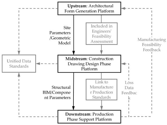
Figure 3.
The relationship between the three existing platform types.
3. Methodology
3.1. Research Framework
Centering on the development of the P-DFMA platform, this study forms a four-stage research framework of status diagnosis, logic construction, technical implementation, and case verification (Figure 4). Each stage is progressive and features two-way feedback. In the status diagnosis stage, the connotation of the P-DFMA term is defined through literature review, and pain points of design-production disconnection are identified through surveys of existing platforms, clarifying core requirements for platform development such as full-process collaboration and manufacturing feasibility verification. In the logic construction stage, four types of rules are refined: mandatory and optional principles for component groups, association rules for component groups, quantity constraint principles for component groups, and distribution derivation and constraint verification rules, forming the core decision-making logic of the platform. In the technical implementation stage, the design logic is transformed into technical solutions, including the construction of a three-level standardization framework, finite element simulation, component library development, and platform architecture implementation. In the case verification stage, the dormitory building project of Tianjin Chengjian University is used as an empirical case to verify the feasibility of the research framework in reverse, while providing optimization feedback for the technical implementation stage.
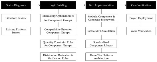
Figure 4.
Research framework.
3.2. Constructing the Design Logic Architecture of Building Product Platform
To address the core contradictions in building industrialization, such as the imbalance between design flexibility and production standardization, multi-stage data fragmentation, difficulty in balancing structural safety and production efficiency, and complex project dynamic decision-making, based on the P-DFMA full-process building product platform architecture, this paper proposes constructing the design logic architecture of the building product platform from four aspects: mandatory and optional rules for component groups, correlation rules for component groups, quantity constraint rules for component groups, and step-by-step derivation and constraint verification rules (Figure 5), realizing integration of “design-production-assembly”.
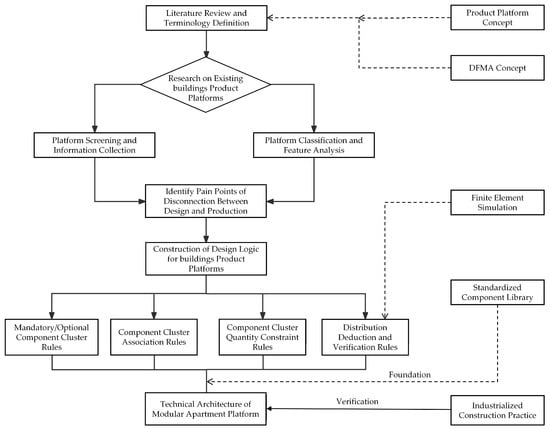
Figure 5.
Design logic architecture for the building products platform.
3.2.1. Mandatory and Optional Rules for Component Groups
The product architecture is defined as a tree-like hierarchical structure: module units, as top-level elements, can be disassembled into several components; connections between and within components need to be realized through connectors. When users select a residential module unit, the system automatically associates light steel keel load-bearing components and high-strength bolt connectors; if two adjacent module units are selected simultaneously, the platform will automatically add transition connectors between modules, clarifying the mandatory correlation of core elements. For example, in the design of dormitory bathroom modules, after selecting the “integral bathroom unit”, waterproof components and pipeline connectors will be compulsorily included in the scheme to ensure functional integrity.
3.2.2. Correlation Rules for Component Groups
Regarding technical adaptability between components, two constraint relationships are set: exclusion and association. If the “light steel keel wall” component group is selected, the system will automatically exclude options related to “traditional masonry walls”; when “prefabricated composite floor slabs” are selected, the platform will synchronously recommend associated components such as “truss reinforcement connectors” to avoid construction problems caused by selection conflicts.
3.2.3. Quantity Constraint Rules for Component Groups
Combined with project scale and technical requirements, quantity thresholds are set for core component groups. After users input project information such as “21,000 m2 dormitory building, 6-story structure”, the system automatically calculates based on the set base rules of constraints. For example, in the design of the dormitory building at Tianjin Chengjian University, this rule ensures that the quantity of load-bearing components meets load specifications, avoiding structural risks caused by excessive material saving.
3.2.4. Step-by-Step Derivation and Constraint Verification Rules
The design process adopts a “state progressive” approach: starting from module unit selection, each operation triggers the rule engine to verify the feasibility of the current scheme. If the distance between module size and site boundary is less than 5 m, the system will prompt adjustment; if component strength verification fails, alternative schemes are automatically recommended. This process terminates only when all parameters meet constraint conditions, reflecting the optimization of “set-based design” over traditional point-by-point design.
The algorithm structure of the constraint rule engine takes four core elements—mandatory and optional principles, component group association rules, component group quantity constraint principles, and distribution derivation constraint verification rules—as its core. These correspond to the definition of mandatory/optional attributes of the product structure, component conflict restrictions, quantity range constraints, and linked selection requirements. For example, combination rules specify the association between bathroom units, waterproof components, and pipeline connector parts; base rules limit the number of modules per floor to ≤12 and the spacing of horizontal connectors to 1.2–1.5 m; the association framework transforms the configuration process into a triple solution of component attribute parameters, four-level rule constraints, and domains. Backtracking search and heuristic pruning are used to improve the efficiency of multi-constraint collaborative processing.
The logical process of the engine follows a closed loop of input, reasoning, verification, and output and is deeply integrated with modular building design and production. In the input stage, project information, customer needs, and technical specifications are parsed—for example, building types are associated with corresponding building codes. In the reasoning stage, rules are executed hierarchically by stage: the general layout stage verifies the matching between the site and building outline; the design stage ensures module-interface compatibility; and the production stage adapts to factory capacity constraints. For example, when designing an integrated bathroom module, dependency rules automatically associate air duct and power interface components. In the verification stage, constraint violations are checked in real time—for example, a pop-up prompt is displayed when the module width exceeds transportation limits, and alternative schemes are recommended. Finally, a configuration list and constraint satisfaction report are output to support subsequent model generation and BOM export.
In terms of implementation strategy, the engine is deployed based on the “front-end-middle-end-back-end” architecture of the configurator. The front end immediately prompts constraint issues (e.g., oversized modules) when components are selected; the middle end parses rules, converts production data, and synchronizes data for multi-party access; and the back end stores rule parameters and execution records and refers to mature platform models to ensure rules run through the entire process from design to production. When new components are added, only rules need to be supplemented without modifying the overall architecture, ensuring easy maintenance.
4. Platform Development
4.1. Constructing the Three-Level Standardization Framework of “Module Unit-Component-Connector”
4.1.1. Module Unit Design
To address structural problems commonly existing in traditional modular prefabricated buildings, such as misalignment of double-floor joints and gaps in exterior wall panel assembly, this study proposes a split-type exterior wall modular design scheme. By deconstructing the external enclosure system into two types of module units (Figure 6), Type A (main module) adopts standard hexahedral units to achieve functional integrity, and Type B (supplementary module) is designed as a double-sided open structure to meet space adaptation needs. Both module units adopt simple, regular, and highly versatile façade designs, forming light and shadow rhythms through staggered window sleeves. Vertical wood-grain grille sunshade components are embedded in some facades to reduce the industrial feel of the building volume. Dark gray metal edging is used around window openings, forming a delicate light–dark contrast with light-colored wall panels.
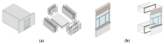
Figure 6.
Two types of module units: (a) Module A standard unit and module A split; (b) B module standard unit and B module split.
In terms of assembly technology, the “staggered lap-joint-gradient supplementary” construction strategy is implemented (Figure 7a–h): Type A modules are first arranged at 1:1 intervals to form the main framework, and in the next stage, Type B modules are embedded into reserved gaps to complete space closure. Especially in the external transverse wall structure, a 3:1 proportion division strategy is adopted, with Type A modules occupying 3/4 of the standard span and Type B modules adapting to the remaining 1/4 span space. Through the size coupling effect of module combination, floor overlapping deviations and exterior wall leakage risks in traditional construction methods are effectively eliminated.
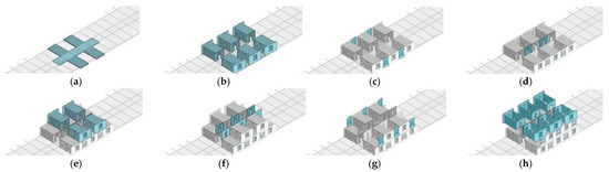
Figure 7.
The construction steps of “displacement and overlap-gradient filling”. (a) Layout of reserved gaps; (b) Type A modules form the initial framework; (c) Embed some Type B modules; (d) Horizontally integrate Type B modules; (e) Fill remaining spaces; (f) Gradient supplement of modules in the external transverse wall area; (g) Near—completion state; (h) Final state of space closure.
4.1.2. Component Design
- 1.
- General Components
General components refer to those that can be reused multiple times, are designed standardly to meet different user needs, and are adaptable to structures of different types and sizes. In the design of general components for dormitory apartment buildings (Figure 8), based on modular construction concepts and prefabricated rapid construction needs, combined with the characteristics of small and medium spans and multi-story loads, the general component structure selects lightweight and high-strength C-shaped steel and U-shaped steel with excellent torsion resistance as the core framework, supplemented by a small number of square steel tubes to strengthen key joints. C-shaped and U-shaped steel are precisely prefabricated through cold bending processes, enabling rapid splicing of standardized components and significantly improving construction efficiency; the closed section of square steel tubes balances corrosion resistance and appearance regularity. The collaborative application of the three not only meets the mechanical stability and spatial adaptability of modular buildings but also reduces transportation and installation costs through lightweight design. The general components of this system adopt a 3 m basic modulus to divide the dual-unit modular system, realizing spatial combinability with topological adaptability.
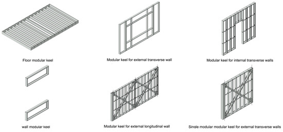
Figure 8.
General components.
- 2.
- Non-General Components
Non-general components refer to those that can be modified or customized but need to follow “rules” when interfacing with general components, used to provide mass customization and meet specific user needs. For prefabricated internal walls and prefabricated stairs, according to the above prefabricated component division principles, production modulus, transportation size, on-site lifting capacity, and connection conditions with adjacent window openings, curtain walls, and platforms are comprehensively considered.
4.1.3. Connector Design
- 3.
- Inter-Component Connector Design
Inter-component connector design details each connection joint. Among them, the connection between walls and floor slabs (Figure 9a) adopts bolting; self-tapping screws penetrate the flange of the floor slab edge beam to form a composite section constraint effect, establishing a shear-compression force transmission path at the slab–wall interface. Connection joints are arranged at standardized modulus intervals to ensure continuous load transmission along the longitudinal direction of components. This structural measure significantly improves interface shear performance and displacement coordination ability through mechanical anchoring and geometric interlocking, realizing reliable connection between horizontal load-bearing components and vertical lateral-resistant components; the connection between walls (Figure 9b) adopts cold-formed square steel tube columns with high-strength bolts as connecting components to achieve precise assembly positioning between walls. The cross-sectional size of cold-formed square steel tubes is consistent with wall thickness, meeting the biaxial bending stiffness requirements of the joint area and conforming to the modulus coordination principle of industrialized buildings; the connection between walls and concrete foundations (Figure 9c) is realized through bar planting anchoring technology, resisting vertical loads and overturning moments through dual force transmission mechanisms of interface friction and bonding anchoring. Meanwhile, an anti-pulling connector system is integrated, with its anchoring end forming a continuous force transmission path with the foundation through chemical bar planting and, together with shear keys, constructing a composite lateral displacement resistance system.
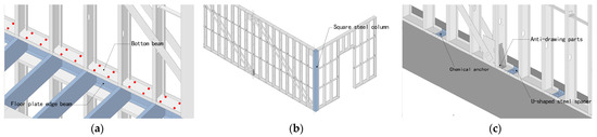
Figure 9.
Inter-component connector design: (a) connection of walls and floors (The red dots represent bolt holes); (b) wall to wall connection; (c) connection between wall and foundation.
- 4.
- Intra-Component Connector Design
Floor slab connector reinforcement design: In the design of floor slab beam joint connections, aiming at the phenomenon of bending moment concentration in the mid-span area, a prestressed steel strip reinforcement (Figure 10a) scheme is adopted. Steel strip reinforcement components are longitudinally arranged at the bottom of the beam, realizing reliable connection with the beam flange through self-tapping screw anchoring technology, and C-shaped cold-formed thin-walled steel support components are set to form a bidirectional constraint system. For shear concentration areas at supports, C-shaped section stiffeners are symmetrically arranged on both sides of the beam web, connected using high-strength bolt groups (Figure 10b).
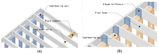
Figure 10.
Intra-component connector design: (a) floor connection reinforcement node 1; (b) floor connection reinforcement node 2.
Wall panel connector reinforcement design: In wall panel reinforcement, steel strips arranged in an X-shaped 45° cross pattern (Figure 11a) form triangular stable units, decomposing the wall into four synergistically working subsystems; meanwhile, double-layer horizontal constraint ring beams (top cold-formed thin-walled steel beams + bottom U-shaped channel steel) are set, combined with lateral U-shaped steel support components to form a three-dimensional space truss system (Figure 11b); finally, rigid connection between columns and beams is realized through high-strength bolt connections.
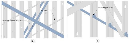
Figure 11.
Wall panel connector reinforcement design: (a) wall panel connection reinforcement node 1; (b) wall panel connection reinforcement node 2.
Corner connector reinforcement design: In corner areas, triangular anti-pulling connectors are set at the four corners of modules (Figure 12a), forming rigid anchoring joints with vertical columns through high-strength bolts to improve corner anti-pulling capacity and rotational stiffness. Anti-pulling components effectively transmit the pulling force generated by vertical seismic action through axial tension, and bolts constrain relative slip of corner components through interface friction and pressure.
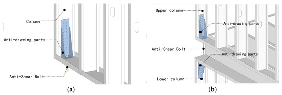
Figure 12.
Corner connector reinforcement design: (a) joint reinforcement node 1; (b) joint reinforcement node 2.
The lightweight light steel keel system reduces reliance on large-scale hoisting equipment. Combined with the precise connection of high-strength bolt joints, the on-site installation error is controlled within 2 mm, far better than the error standard of traditional construction methods. From the perspective of material processing, in accordance with the Technical Code for Cold-Formed Thin-Walled Steel Structures (GB/T 50018-2025) [47], high-precision cold bending forming technology is adopted, and raw materials are precisely processed using professional equipment, resulting in a component dimensional accuracy of ±0.5 mm. For example, when a factory produces light steel keels, the key dimensions, such as flange width and web height, are controlled within the allowable deviation of ±0.3 mm and ±0.5 mm. In the connection link, high-strength bolt joints use bolt holes processed by CNC (Computer Numerical Control) drilling technology, with a hole position accuracy of ±0.3 mm. In a large-scale light steel building project, for instance, a sample inspection of a large number of bolt holes showed that all met this accuracy standard. During on-site installation, positioning rulers with scales and laser levels with an accuracy of ±1 mm are used for real-time calibration, ensuring that the axis alignment and elevation deviation during keel splicing are within 1 mm, which is verified by relevant project acceptance records.
4.2. Improving Manufacturing Feasibility Through Finite Element Simulation
After the structural design of modular units is completed, SimSolid finite element analysis software is used to build a 3D model, and stress simulation verification is conducted on the entire modular unit, floor slabs, and various wall panels under multiple working conditions, including static loads, wind loads, seismic actions, and dynamic loads. The material used is Q345 steel conforming to GB standards (elastic modulus: 2.06 × 10⁸ kN/m2, Poisson’s ratio: 0.3, bulk density: 76.98 kN/m3). Under the combined static and vertical load conditions (Figure 13), including 1.3 times the permanent load (equipment point load: 1.5 kN/m2) and 1.5 times the live load (snow load: 0.55 kN/m2, roof live load: 2.0 kN/m2), the maximum displacement of the entire module is approximately 0.32 mm, and the displacement shows a uniform decreasing trend along the spatial position. The displacement range of all measurement points is 1.39 × 10⁻³–0.32 mm, which is lower than the conventional allowable deformation threshold of 0.1–1 mm in engineering. The maximum displacement of the floor slab simulated independently is only 1.9787 × 10⁻¹ mm, the maximum displacement of the transverse wall simulated independently is only 5.2199 × 10⁻¹ mm, and the maximum displacements of the two longitudinal walls simulated independently are 2.7 × 10⁻¹ mm and 3.7 × 10⁻¹ mm, respectively. The displacements all show a regular decreasing trend along the structural surface, confirming their extraordinary stiffness performance, and the deformation meets the requirements of the Standard for Testing Technology of Building Structures (GB/T 50344-2019) [48].
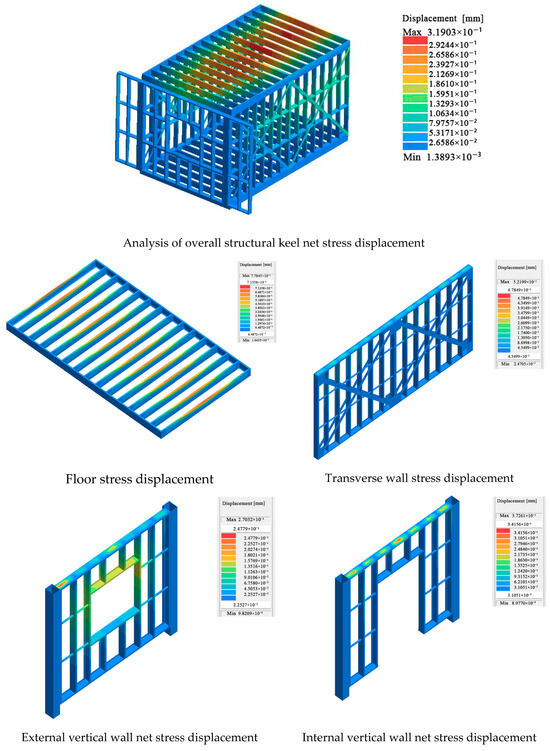
Figure 13.
Finite element stress simulation.
The wind load stress is calculated in accordance with the Code for Loads on Building Structures (GB 50009-2012) [49], with the standard wind load value usually taken as 1.5 kN/m2. The seismic load stress is determined in accordance with the Code for Seismic Design of Buildings (GB/T 50011-2010, 2016 edition) [50]. According to the seismic fortification intensity of seven degrees in Tianjin, flat site conditions, and structural natural vibration characteristics, the seismic influence coefficient is determined to be 0.08, and the structural internal forces and stresses under seismic action are calculated. As shown in the figure, under wind load and seismic load (Figure 14), the maximum horizontal displacement of the structure is 0.57 mm (calculated value), which meets the standard limit requirements. For dynamic load conditions (Figure 15), modal and harmonic response analysis using SimSolid verifies that the natural frequency of the module is 38.5 Hz, and the peak dynamic stress under dynamic load is 113 MPa, which is within the yield strength standard value of 345 MPa for Q345 steel [51].
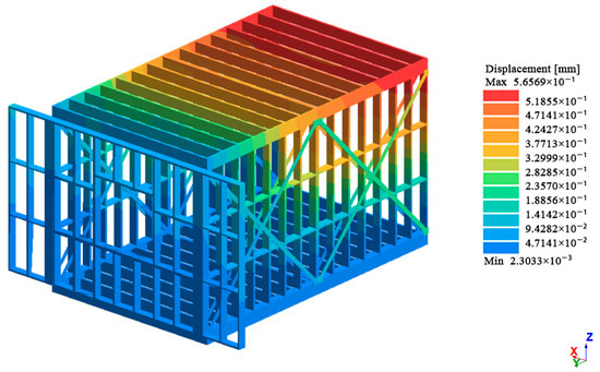
Figure 14.
Analysis of wind load and seismic load working conditions.
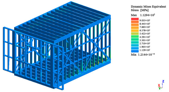
Figure 15.
Analysis of dynamic load working conditions.
After the structural design of the three-layer module assembly is completed, a 3D model is built using SimSolid finite element analysis software to conduct stress simulation verification on the overall module under static load, wind load, and seismic action conditions (Figure 16). The Q345 steel used complies with the GB/T 1591-2018 standard [51]. Under the combined static and vertical load conditions, the maximum displacement of the overall module is approximately 0.93 mm, with the displacement of each component showing a regular decreasing trend along the structural surface, meeting the requirements of the Standard for Testing Technology of Building Structures GB/T 50344-2019 [48]. Indicators such as the maximum horizontal displacement of the structure under wind load and seismic load also meet the specifications. The peak dynamic stress under dynamic load is within the yield strength range of Q345 steel, verifying the reliability of the structure.
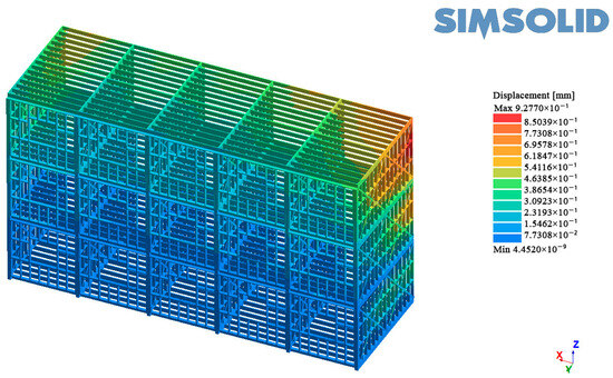
Figure 16.
Analysis of three-layer module splicing.
4.3. Creating a Component Library for Modular Apartments
As the core data support for the P-DFMA platform to realize modular design, the component library (Figure 17) covers various core components required for the full life cycle of modular apartment buildings. Through standardized data formats and structured storage methods, it provides accurate data support for platform scheme design. Based on the three-level standardization framework of “module unit-component-connector” and combined with functional requirements and technical parameters of the modular dormitory building project at Tianjin Chengjian University, this study constructs a comprehensive component library system including structural components, connecting components, and door and window components.
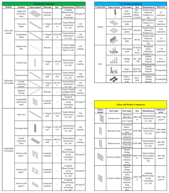
Figure 17.
Component library for modular apartments.
The component library interacts with the application layer of the P-DFMA platform through a unified data interface. Each component entry contains four categories of metadata: basic attributes (name, model, material), technical parameters (size, performance indicators), production information (manufacturer, price), and association rules (adaptable modules, compatible components), supporting multi-dimensional retrieval by function type, material characteristics, performance parameters, etc. Through the construction of this component library, the platform can realize rapid combination and verification of modular schemes.
4.4. Building the P-DFMA Platform Architecture for Modular Apartments
The three-layer architecture design of the modular apartment platform adopts “data-application separation” to avoid system reconstruction risks. The multi-user collaborative permission system supports real-time data sharing among architects, engineers, and manufacturers, significantly reducing cross-link communication costs, laying a solid technical foundation for the integration of “design-production-assembly” in industrialized buildings, and accelerating the implementation of digital transformation in the construction industry. The specific platform architecture is shown in the figure (Figure 18):
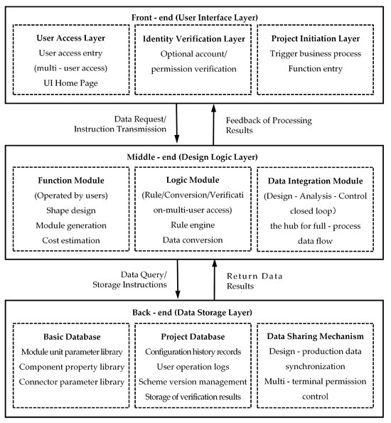
Figure 18.
P-DFMA platform architecture for modular apartments.
4.4.1. Front-End (User Interface Layer)
As the interaction layer directly accessible to users, the front-end focuses on visual operation and real-time feedback, consisting of three parts: User Access Layer: builds multi-user access portals, with the UI homepage as the carrier, supporting users to easily access the system and start the design process. Identity Verification Layer: provides optional account/permission verification mechanisms to ensure that different roles access system functions as needed and strengthens data security. Project Initiation Layer: serves as the entry point for triggering business processes, allowing users to initiate projects from here, promote the flow of design tasks, and connect to subsequent functional modules. Through data requests and command transmission, the front end converts user operations into requirements and simultaneously receives processing results fed back by the middle end, realizing real-time presentation of design intentions.
4.4.2. Middle-End (Design Logic Layer)
The middle-end carries the core logic of the system and connects the closed loop of design, analysis, and management, consisting of three parts: Function Modules: which focus on user direct operation scenarios, covering form design, module generation, cost estimation, etc., and convert front-end interactions into design results. Logic Modules: which rely on the rule engine to handle component compatibility and quantity constraints and convert design schemes into production-ready data through data conversion tools, connecting multi-disciplinary collaboration. Data Connection Modules: which serve as the hub for full-process data flow. After receiving front-end commands, they initiate data query/storage requests to the back-end and then feed back the returned results to the front-end, ensuring closed-loop data flow for design, analysis, and management.
4.4.3. Back-End (Data Storage Layer)
The back-end is based on a database and builds a storage, sharing, and traceability system consisting of three core units: Basic Database: which stores basic data such as modular unit parameters, component attributes, and connector parameters, providing standards for design and production and ensuring a reliable basis for scheme implementation. Project Database: which records project history, user operation logs, scheme versions, verification results, etc., forming a full-lifecycle data file for the project and supporting process traceability and version management. Data Sharing Mechanism: which realizes synchronous design-production data and multi-terminal permission control, achieving a unified data source for design, production, and construction, and facilitating full-lifecycle traceability of industrialized building products such as prefabricated components. The middle-end and back-end interact through data query and storage commands, and the back-end returns processing results to provide data support for the middle-end’s logical operations and function execution.
5. Case Verification
This chapter takes the modular apartment project at Tianjin Chengjian University as a case, completing the full-process practice from site environment analysis to production implementation based on core components and architecture design of the building product platform. Through closed-loop verification of environment adaptation, design deepening, and production transformation, this case highlights the application value of the platform in industrialized construction projects. The project is located in the core area of Tianjin Chengjian University campus, with an overall six-story standardized design and a total construction area of approximately 21,000 m2.
5.1. Environment Adaptation and Master Plan Layout Design
Environmental analysis and master plan layout are the starting points of project design. The platform realizes accurate integration of site data and generation of building outlines through master plan layout components, laying a compliance foundation for subsequent design. Based on the project site location (core area of Tianjin Chengjian University campus), key geographical data such as relevant current site information, surrounding existing buildings (north dormitory building, west canteen), and Mingfei Lake waterfront landscape are input. Through data visualization functions, planners clarify core site constraints: connecting to the south urban road, undertaking pedestrian flow from the west canteen, retaining the view of the central axis landscape corridor, and avoiding areas with dense underground pipelines, providing objective data support for master plan layout.
Based on actual site conditions, the platform’s master plan layout components generate building outlines with “functional adaptation + regulatory compliance” as the core. Combined with campus planning requirements, the site needs to balance building density and landscape resources. The platform finally determines a reasonable layout through multi-scheme comparison: arranging symmetrical modular groups based on the central axis, with two dormitory buildings extending east–west, not only echoing the campus axis sequence but also realizing a gradual transition with the skyline of existing buildings through setback design.
In the master plan interface (Figure 19), technical and economic indicators of the site can be intuitively viewed, such as a total construction land area of 14,175 m2 and a plot ratio of 0.7, assisting planners in quickly verifying density constraints; meanwhile, through the “Site Entrance”, the traffic organization strategy of the main entrance connecting to the south urban road and the west pedestrian entrance undertaking canteen pedestrian flow is clearly presented, verifying the functional rationality of the master plan layout. During generation, the platform automatically verifies core constraints: in accordance with Tianjin planning regulations, the building height is controlled within 24 m (six-story design) to avoid blocking the central axis landscape corridor.
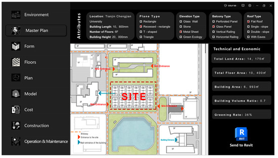
Figure 19.
Master plan interface.
5.2. Form Design and Model Generation
Based on the master plan layout, the platform optimizes schemes through the form design module and then completes the transformation from conceptual design to manufacturable models through the model generation module, verifying the platform’s rule-driven and data integration capabilities.
5.2.1. Form Design Module
In the scheme generation stage, core site parameters are input. Combined with functional requirements and landscape resource utilization, the design team selects a “rectangular frame” layout—a symmetrical modular group extending east–west along the axis. This not only echoes the campus axis sequence but also realizes dynamic and static zoning through the enclosed courtyard (e.g., dynamic functions such as fitness areas and art exchange areas are separated from static functions such as study areas and accommodation areas). The interface clearly presents the functional zoning logic diagram(Figure 20), distinguishing “dynamic areas (fitness, communication), transition areas (work, academic), and static areas (study, accommodation)” through color coding, verifying the platform’s rule verification capability for “function-space” matching in form design. Meanwhile, the building form preview intuitively shows the connection between the scheme and the general layout, ensuring design continuity.
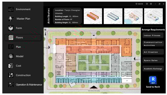
Figure 20.
The functional zoning logic interface.
Based on the “rectangular frame” outline and equipped with standard modules for 2–3 person rooms, the platform automatically adjusts the module arrangement to meet the Code for Fire Protection Design of Buildings (GB 50016) [52]. The underlying calculation logic is that, combined with the given compliance evacuation distance of 21 m and exit width of 1.8 m, the calculation is performed in accordance with the fire evacuation simulation requirements for high-rise residential buildings. In terms of total evacuation time, calculated with an early warning delay time of 60 s and a personnel evacuation speed of 1.2 m/s, the path walking time is 17.5 s, and the total evacuation time is 77.5 s, which meets the compliance requirement of ≤300 s. In terms of exit evacuation capacity, taking the single-exit passage capacity coefficient of 1.3 persons/(m·s), 2 exits, and a safe evacuation time of 300 s, the total exit evacuation capacity reaches 1404 persons, which can meet the accommodation needs of 2–4 persons per room, and the exit capacity meets the demand.
Calculation process:
Total Evacuation Time = Early Warning Delay Time + Path Walking Time
Path Walking Time = Evacuation Distance ÷ Evacuation Speed = 21 m ÷ 1.2 m/s = 17.5 s
Total Evacuation Time = 60 s + 17.5 s = 77.5 s
Total Exit Evacuation Capacity = Single–Exit Passage Capacity × Number of Exits × Safe Evacuation Time
Single–Exit Passage Capacity = Exit Width × Passage Capacity Coefficient = 1.8 m × 1.3 persons/(m⋅s) = 2.34 persons/s
Total Exit Evacuation Capacity = 2.34 persons/s × 2 × 300 s = 1404 persons
In addition, the platform generates a differentiated entrance and exit scheme based on site pedestrian flow characteristics: the south main entrance is set to connect to the urban road, maximizing the use of the Mingfei Lake waterfront landscape; the west pedestrian main entrance is set to undertake the dense pedestrian flow from the canteen; and the north and east secondary entrances are set to ensure the convenience of students’ daily activity routes, realizing dual optimization of landscape utilization and traffic efficiency. Through axis space topology analysis, this layout is fully compatible with the existing campus space structure.
5.2.2. Model Generation Module
Based on the determined axis network parameters (bay width 3.6 m, depth 6.0 m) and size constraints, the platform retrieves corresponding modules from the P-DFMA standardized component library and automatically assembles them to generate a complete BIM model. The model covers production details such as dimensional accuracy of prefabricated components, connection joints (e.g., connection rules for surfaces a/b of modules A/B), and installation sequence, which can directly guide factory production without multiple engineering refinements.
The model interface shows module connection logic through 3D views (Figure 21), with clear identifiers presenting connection rules for “Module A-a face and Module B-a face, Module A-b face and Module B-b face”, verifying the platform’s ability to check assembly relationships of prefabricated components; meanwhile, the content library categorically displays components such as “modules, furniture, doors and windows, balconies”, reflecting the standardization and reusability of the platform’s component library.
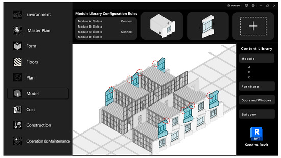
Figure 21.
Module connection logic interface(The red circles mark the positions between modules where overlapping errors tend to occur during joining).
5.3. Production Model Transformation
After design completion, the platform enters the production model transformation stage: designers first complete module selection initialization for a single suite, including details such as module combination (“bedroom + independent bathroom” standard module), wall type (prefabricated lightweight partition wall), and door and window type (broken-bridge aluminum casement window). The model interface (Figure 22) intuitively presents the integration degree of the project with the campus environment–buildings are symmetrically arranged along the central axis, and the enclosed courtyard echoes the Mingfei Lake landscape, verifying the platform’s ability to check “building–environment” synergy in the scheme design stage; meanwhile, the refined building appearance (e.g., metal sheet facade, glass curtain wall main entrance) shows the platform’s degree of “design intention-manufacturing implementation” in production model generation, reflecting the advantages of industrialized construction.
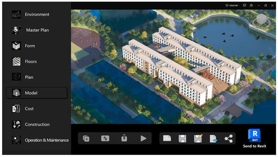
Figure 22.
Model interface.
After parameter confirmation, the platform retrieves site data and layout data from the database, automatically matches prefabricated wall panels, floor slabs, stairs, and other component models from the product database, imports project files, and completes assembly according to position parameters to generate an enhanced BIM model containing detailed component information.
5.4. Cost Savings Based on the P-DFMA Platform
1. Multidisciplinary Labor Costs
According to information from Buildhr.com [53], the monthly labor cost for architectural designers is CNY 7000.
Traditional model: A cross-disciplinary team of 35 people is required, including 8 architects, 8 structural engineers, 10 MEP (mechanical, electrical, plumbing) engineers, and 9 BIM modelers. Due to repeated iterations caused by model conflicts, the total construction period is 80 days. Calculation formula: 35 people × 2.67 months × 7000 CNY/person/month = CNY 654,150.
DFMA model: The rule engine automatically matches the parameters of the component library, reducing the team size to 18 people and shortening the construction period to 60 days. Calculation formula: 18 people × 2 months × 7000 CNY/person/month = CNY 252,000.
2. Third-Party Review Fees
In accordance with the Notice on Standardizing the Charging Standards for Construction Drawings Design Document Review (Jinjiaguan [2011]. No. 46) [54], the basic fee for building review is 1.7 CNY/m2, and a 50% service fee is added for re-review.
Traditional model: Since the indicators such as evacuation distance and fire compartment fail to meet the requirements of the Code for Fire Protection Design of Buildings (GB 50016-2014) [52], two rounds of review are required. Calculation formula: 21,000 m2 × 1.7 CNY/m2 × (1 + 50%) = CNY 53,550.
P-DFMA model: The platform has a built-in database of current codes, and the design results are automatically verified for compliance, so only one round of review is needed to pass. Calculation formula: 21,000 m2 × 1.7 CNY/m2 = CNY 35,700.
3. Component Processing Costs
As mentioned in the Summary and Case Illustration of Steel Structure Engineering Cost Analysis [55], the unit price of processing and manufacturing fees in steel structure projects is 32 CNY/m2.
Traditional model: The lack of data collaboration leads to processing deviations, with a total cost of 21,000 m2 × 32 CNY/m2 = CNY 672,000.
P-DFMA model: The parameters of the component library are directly connected to the factory’s CNC drilling equipment, reducing the secondary processing fee by 15 percentage points. Calculation formula: 21,000 m2 × 32 CNY/m2 × (1–15%) = CNY 504,000.
4. Material Waste Costs
Based on the project’s material purchase orders and the waste rate limit requirements specified in the Technical Standard for Cold-Formed Thin-Walled Steel Structures (GB/T 50018-2025) [47], the steel consumption of the 21,000 m2 building is 5000 tons, and the unit price of steel is 4500 CNY/ton.
Traditional model: Disordered manual nesting results in a 6% waste rate.
Calculation formula: 5000 tons × 4500 CNY/ton × 6% = CNY 1,350,000.
P-DFMA model: Optimized nesting is carried out according to modular units (e.g., the keels of Type A standard modules uniformly adopt a length of 3.6 m), reducing the waste rate to 2%. Calculation formula: 5000 tons × 4500 CNY/ton × 2% = CNY 450,000.
5. Cross-Party Communication and Coordination Fees
In accordance with the Notice of the State Development Planning Commission on Issuing the Interim Provisions on Charges for Preparatory Consulting Services of Construction Projects (Jijia Ge [1999]. No. 1283) [56] and the Notice of Tianjin Municipal Development and Reform Commission on Issues Concerning Service Charge Standards for Some Construction Projects (Jinfagai Jiaguan [2014]. No. 716) [57], the one-time fee for a coordination meeting involving multiple parties (including designers, factories, constructors, supervisors, etc.) is set at CNY 13,000.
Traditional model: Frequent design changes and component dimensional deviations lead to approximately 30 coordination meetings [58]. Total cost: 30 meetings × 13,000 CNY/meeting = CNY 390,000.
P-DFMA model: Real-time shared data dashboards for design progress, production status, and installation errors enable remote resolution of collaboration issues, requiring only 13 meetings. Calculation formula: 13,000 CNY/meeting × 13 meetings = CNY 169,000.
6. Rework and Repair Costs
An analysis of 19,605 rework incidents across 346 construction projects shows that the average rework rate of construction projects is 4%, with a rework cost of 60 CNY/m2 [59].
Traditional model: With a 4% rework rate, the rework cost includes expenses for component removal, reinstallation, and sealing treatment. Calculation formula: 21,000 m2 × 4% × 60 CNY/m2 = CNY 50,400.
P-DFMA model: The installation accuracy of high-strength bolt joints, combined with laser positioning calibration, reduces the rework rate by more than 50% (i.e., to 2%).
Calculation formula: 21,000 m2 × 2% × 60 CNY/m2 = CNY 25,200.
By comparing the cost differences between the P-DFMA platform model and the traditional prefabricated construction model (Table 3), the results show that in the dimensions of multi-disciplinary labor costs, third-party review fees, component processing costs, material waste costs, cross-party communication and coordination fees, and on-site rework and repair fees, the P-DFMA platform model reduces design labor costs by 61.4%, third-party review fees by 33.3%, and so on. Ultimately, the platform achieves a 54.8% cost savings rate in project design, production, and cross-link collaboration, which verifies the value of the platform in reducing costs for prefabricated construction projects.
Table 3.
Cost savings based on the P-DFMA platform.
6. Discussion
6.1. Multi-Dimensional Benefits of the P-DFMA Technology System
The P-DFMA technology system constructed in this study achieves efficiency improvement and value optimization throughout the entire process of modular buildings through multi-dimensional innovations. In terms of cost and environmental protection, the three-level standardization framework of “modular unit-component-connector” promotes centralized procurement and specialized manufacturing. It not only reduces material waste rates through precise installation but also reduces redundant resource consumption through the intensification of supply chain logistics, thus realizing the coordination of economic benefits and ecological benefits. Taking the Tianjin Chengjian University project as an example, the mass production of standardized components increases the reuse rate of building materials.
The technology system achieves a dynamic balance between performance and practicality. The lightweight light steel keel system (95% of components can be transported and installed manually) reduces reliance on large-scale hoisting equipment. Combined with the precise connection of high-strength bolt joints, the on-site installation error is controlled within 2 mm, which is far better than the error standard of traditional construction methods. The verification of the mechanical properties of key joints through SimSolid finite element simulation effectively avoids later rework caused by unreasonable design. At the same time, by laying out modular manufacturing centers in underdeveloped areas, the system creates standardized jobs, alleviates the problem of skill shortages in the industry, and realizes the extension of social benefits.
In terms of digital collaboration, the full-process platform architecture builds a data closed loop for “design-production-assembly”. For example, the user-friendly operation interface for non-professionals (such as the parametric adjustment function for the number of suites) reduces reliance on professional BIM software, enabling the design team to focus on scheme innovation rather than tool operation, which significantly improves the efficiency of design iteration.
6.2. Platform Expansion Directions for Complex Building Types
To adapt to projects for other purposes, the platform will be expanded in multiple aspects. For hospitals, it is necessary to add special functional modules such as operating rooms and ICUs, embed medical-specific constraint rules, and strengthen simulations of cleanliness and air distribution. For large commercial facilities, it is required to develop flexible space modules, build rules for multi-scenario switching, and deepen data collaboration with operation systems. For high-rise residential buildings, it is essential to optimize lateral force resistance modules and vertical transportation modules and add analyses of wind-induced vibration comfort and vertical deformation coordination. For mixed-use projects, it is necessary to establish a component library that combines a general foundation with special extensions, build cross-functional collaboration rules, and integrate full-life-cycle data to realize efficient connection and collaborative operation of various functional modules. At the same time, it is necessary to continuously improve the ability to handle complex working conditions, reduce the threshold for using the component library, and innovate cross-link collaboration models.
6.3. Data Dependence of the Standardized Component Library
The standardized component library’s dependence on manufacturer data faces problems such as the lack of industry data sharing and low supply willingness of small and medium-sized contractors, which may increase the initial setup and maintenance costs. To address this, on the one hand, an interest-binding mechanism can be established: manufacturers that proactively provide data are given priority in project recommendations, and data leakage risks are avoided through non-disclosure agreements. At the same time, lightweight collection tools are developed, providing modular templates and mobile data collection functions to simplify the data upload process for small and medium-sized contractors. On the other hand, third-party data resources are introduced: by connecting to industry testing agency databases and market-oriented data service providers, the supply gap of manufacturers is filled; the back end sets up data validity reminders and user feedback portals to dynamically update data and ensure the timeliness of the component library.
7. Conclusions
This study constructs a P-DFMA-based modular apartment building product platform technology system, realizing seamless connection from design to construction. The research establishes a three-level standardization framework of “modular unit-component-connector”, clarifying module combination rules and interface constraints; verifies the mechanical properties of key joints through finite element simulation to ensure manufacturing feasibility; builds a standardized library containing structural components, connecting components, and door and window components to support rapid scheme combination; and constructs a “front-end-middle-end-back-end” full-process collaborative platform architecture to connect the data flow closed loop. The case of the dormitory building at Tianjin Chengjian University verifies the feasibility and value of the hierarchical architecture building product platform in the field of industrialized construction. On the one hand, it confirms the feasibility of the new model of “design driven by manufacturable components”—that is, conducting design based on a component library containing manufacturing knowledge can avoid later production rework and alleviate supply chain pressure. On the other hand, it also verifies the advantages of the hierarchical architecture: core functions can be completed outside proprietary BIM software, and BIM applications can be extended to the full product life cycle. In addition, it demonstrates the multi-functionality and expandability of the building product platform: its core functions are modular and can be extended to data analysis. Furthermore, it verifies the potential value of the building product platform in optimizing the time, cost, and quality of construction projects, laying a foundation for subsequent related quantitative research.
Future research needs to be deepened in the three following aspects:
- While ensuring the current core function of assembly collaboration, the platform will gradually enhance its ability to handle complex working conditions: (1) Within 1–2 years, optimize the two-way data interface with third-party mechanical software such as SimSolid and PKPM to reduce manual conversion and improve closed-loop efficiency; (2) Within 2–3 years, embed a simplified mechanical calculation module, while still connecting to third-party software for special scenarios; (3) Within 3–5 years, develop a dedicated mechanical model based on platform assembly data to realize the built-in calculation of complex working conditions, forming a fully functional closed loop for assembly efficiency optimization and structural performance assurance.
- Develop an automatic component library generation algorithm to reduce the threshold for initial database construction.
- Study the organizational model of real-time collaboration between manufacturers and designers to break through cross-link collaboration barriers and promote the upgrading of modular construction industrialization towards intelligence.
Author Contributions
Conceptualization, F.L. and M.W.; methodology, J.W.; software, X.L. and M.W.; validation, M.W., F.L., and X.L.; formal analysis, M.W.; investigation, X.L.; resources, F.L.; data curation, X.L.; writing—original draft preparation, M.W.; writing—review and editing, M.W.; visualization, M.W.; supervision, F.L. and J.W.; project administration, J.W.; funding acquisition, F.L. All authors have read and agreed to the published version of the manuscript.
Funding
This research was funded by the Tianjin Chengjian University Educational Teaching Reform and Research Project: Research and Practice on Progressive Curriculum System of Architectural Construction Based on Technology-Enabled Design.
Data Availability Statement
The data supporting the reported results in this study are primarily derived from the practical process and related technical documents of the modular dormitory building design project at Tianjin Chengjian University. The core data generated in the study include parameters of the “module unit-component-connector” three-level standardization framework, raw calculation data from finite element simulations (SimSolid), metadata of the standardized component library (including technical parameters and association rules of structural components, connecting components, and door/window components), as well as design schemes and production transformation model data during the case verification phase. Due to the involvement of specific project technical details and partner information, the aforementioned data have not been publicly archived. For access to relevant data, requests can be made through contact with the corresponding author (email: lifeng@tcu.edu.cn) for negotiation. We will provide necessary support under the principles of data security and privacy protection. This study strictly adheres to MDPI’s data policies, ensuring that data usage complies with ethical standards.
Acknowledgments
Thanks to the Tianjin Technology Innovation Center for New Industrialized Prefabricated Buildings for providing practical support and technical materials, which laid the foundation for the theoretical verification of this study. Gratitude is extended to all experts and scholars for their professional guidance, as well as to laboratory colleagues for their technical assistance in simulation analysis and component library construction. During the preparation of this manuscript, Doubao (web version) was used for text proofreading and language optimization. The authors have thoroughly reviewed and edited the output and take full responsibility for the entire content of this publication. Sincere thanks are expressed to all individuals and institutions that provided support.
Conflicts of Interest
Author Xinrui Li was employed by the company Tianjin Architecture Design Institute Co., Ltd. The remaining authors declare that the research was conducted in the absence of any commercial or financial relationships that could be construed as a potential conflict of interest.
Abbreviations
The following abbreviations are used in this manuscript:
| P-DFMA | Platform-Design for Manufacture and Assembly |
| DFMA | Design for Manufacture and Assembly |
| BIM | Building Information Modeling |
References
- Wang, Z.; Hu, T.; Liu, J. Decoupling economic growth from construction waste generation: Comparative analysis between the EU and China. J. Environ. Manag. 2024, 353, 120144. [Google Scholar] [CrossRef]
- Bryden Wood. Platforms in Practice: A Lean Approach to Industrialised Construction; Bryden Wood: London, UK, 2023; pp. 1–107. [Google Scholar]
- Lim, J.Y.; Wang, S.Q.; Tiong, R. Precasting in Singapore’s Design & Build Projects. Int. J. Constr. Manag. 2002, 2, 1–12. [Google Scholar] [CrossRef]
- Roxas, C.L.; Bautista, C.R.; Dela Cruz, O.G.; Dela Cruz, R.L.; De Pedro, J.P.; Dungca, J.R.; Lejano, B.A.; Ongpeng, J.M.C. Design for Manufacturing and Assembly (DfMA) and Design for Deconstruction (DfD) in the Construction Industry: Challenges, Trends and Developments. Buildings 2023, 13, 1164. [Google Scholar] [CrossRef]
- Laovisutthichai, V.; Lu, W. Design for manufacture and assembly (DfMA) in architectural design meetings: From a case study to knowledge-to-action framework. Smart Sustain. Built Environ. 2022, 12, 1117–1134. [Google Scholar] [CrossRef]
- Hammad, A.W.; Akbarnezhad, A.; Wu, P.; Wang, X.; Haddad, A. Building information modelling-based framework to contrast conventional and modular construction methods through selected sustainability factors. J. Clean. Prod. 2019, 228, 1264–1281. [Google Scholar] [CrossRef]
- Widanage, C.; Kim, K.P. Integrating Design for Manufacture and Assembly (DfMA) with BIM for infrastructure. Autom. Constr. 2024, 167, 105705. [Google Scholar] [CrossRef]
- He, Q.F.; Zou, J.M.; Zhang, C.F.; Zhong, Y.; Li, J.S.; Yi, W.J. Experimental study on the seismicperformance of two-storey UHPC modular building structure. J. Build. Eng. 2024, 97, 110966. [Google Scholar] [CrossRef]
- Zhang, X.; Ming, X.; Liu, Z.; Qu, Y.; Yin, D. A framework and implementation of Customer Platform-connection manufactory to service (CPMS) model in product service system. J. Clean. Prod. 2019, 230, 798–819. [Google Scholar] [CrossRef]
- Zhang, L.L.; Jiao, R.J.; Huang, G.; Maccarthy, B.L. Extended Guest Editorial: Smart Product Platforming in the Industry 4.0 Era and Beyond. Int. J. Prod. Econ. 2024, 280, 109490. [Google Scholar] [CrossRef]
- ElMaraghy, H.; AlGeddawy, T. A Methodology for Modular and Changeable Design Architecture and Application in Automotive Framing Systems. J. Mech. Des. 2015, 137, 121403. [Google Scholar] [CrossRef]
- General Motors, Co. General Motors to Outline Plans for Decade of Growth, Doubling of Annual Revenues by 2030 with Increased Margins [Press Release]. General Motors Investor Relations. Available online: https://investor.gm.com/news-releases/news-release-details/general-motors-outline-plans-decade-growth-doubling-annual (accessed on 15 August 2025).
- Kang, H.Y. Digital Platform Complementors and the Number of Product Features: Evidence from the Apple iOS App Store. Br. J. Manag. 2023, 35, 854–870. [Google Scholar] [CrossRef]
- Carlisle, B.; Webb, P. Construction kits: A platform for improving how civil engineers deliver infrastructure. Proc. Inst. Civ. Eng.-Civ. Eng. 2021, 174, 10. [Google Scholar] [CrossRef]
- Montazeri, S.; Lei, Z.; Odo, N. Design for Manufacturing and Assembly (DfMA) in Construction: A Holistic Review of Current Trends and Future Directions. Buildings 2024, 14, 285. [Google Scholar] [CrossRef]
- Nguyen, D.C.; Jeon, C.H.; Roh, G.; Shim, C. BIM-based preassembly analysis for design for manufacturing and assembly of prefabricated bridges. Autom. Constr. 2024, 160, 105338. [Google Scholar] [CrossRef]
- Lu, W.; Tan, T.; Xu, J.; Wang, J.; Chen, K.; Gao, S.; Xue, F. Design for manufacture and assembly (DfMA) in construction: The old and the new. Archit. Eng. Des. Manag. 2020, 17, 77–91. [Google Scholar] [CrossRef]
- Yuan, Z.; Sun, C.; Wang, Y. Design for Manufacture and Assembly-oriented parametric design of prefabricated buildings. Autom. Constr. 2017, 88, 13–22. [Google Scholar] [CrossRef]
- Formentini, G.; Rodríguez, N.B.; Favi, C. Design for manufacturing and assembly methods in the product development process of mechanical products: A systematic literature review. Int. J. Adv. Manuf. Technol. 2022, 120, 4307–4334. [Google Scholar] [CrossRef]
- Bogue, R. Design for manufacture and assembly: Background, capabilities and applications. Assem. Autom. 2012, 32, 112–118. [Google Scholar] [CrossRef]
- Rozali, A. Product Design Improvement Through Design for Manufacture and Assembly (DFMA) and Theory of Inventive Problem Solving (TRIZ). Ph.D. Thesis, Universiti Teknologi Malaysia, Johor Bahru, Malaysia, 2010. [Google Scholar]
- Wen, X.; Teng, Y.; Shen, G.Q. Extended end-of-life carbon assessment and savings: A case study of steel-framed modular buildings in Hong Kong. Build. Environ. 2024, 266, 112056. [Google Scholar] [CrossRef]
- Gibb, A.G.F. Off-Site Fabrication: Principles, Processes, and Management; Taylor & Francis: Abingdon, UK, 2018. [Google Scholar]
- Cao, J.; Bucher, D.F.; Hall, D.M.; Lessing, J. Cross-phase product configurator for modular buildings using kit-of-parts. Autom. Constr. 2021, 123, 103437. [Google Scholar] [CrossRef]
- Xu, L.; Zou, Y.; Lu, Y.; Chang-Richards, A. Automation in manufacturing and assembly of industrialised construction. Autom. Constr. 2024, 170, 105945. [Google Scholar] [CrossRef]
- Arenas, S.R.; Osorio-Gómez, G. Integration of DFMA Throughout an Academic Product Design and Development Process Supported by a PLM Strategy. In Proceedings of the International Conference on Engineering Design, ICED11, Lyngby, Denmark, 15–18 August 2011. [Google Scholar]
- Ghodsian, N.; Benfriha, K.; Olabi, A.; Gopinath, V.; Arnou, A.; Charrier, Q. Toward designing an integration architecture for a mobile manipulator in production systems: Industry 4.0. Procedia CIRP 2022, 109, 443–448. [Google Scholar] [CrossRef]
- Johnston, J. Delivery Platforms for Government Assets: Creating a Marketplace for Manufactured Spaces; Bryden Wood: London, UK, 2017; Available online: http://www.brydenwood.co.uk/resources/e-books/s36467/ (accessed on 15 August 2025).
- Boldt, S.; Linnéusson, G.; Rösiö, C. Exploring the Concept of Production Platforms—A literature review. Procedia CIRP 2021, 104, 158–163. [Google Scholar] [CrossRef]
- Royal Institute of British Architects. “RIBA Publishes New Design for Manufacture and Assembly Guidance”. Specificationonline. 20 September 2021. Available online: https://specificationonline.co.uk/articles/2021-09-20/riba/riba-publishes-new-design-for-manufacture-and-assembly-guidance (accessed on 15 August 2025).
- Emmatty, F.J.; Sarmah, S.P. Modular product development through platform-based design and DFMA. J. Eng. Des. 2012, 23, 696–714. [Google Scholar] [CrossRef]
- Said, H.M.; Chalasani, T.; Logan, S. Exterior prefabricated panelized walls platform optimization. Autom. Constr. 2017, 76, 1–13. [Google Scholar] [CrossRef]
- Popovic, D.; Elgh, F.; Heikkinen, T. Configuration of flexible volumetric elements using product platforms: Information modeling method and a case study. Autom. Constr. 2021, 126, 103661. [Google Scholar] [CrossRef]
- Ismail, T.; Saeed, A.; Elkharbotly, A.; Zamzam, N. Product platform design for minimum cost in mass customization manufacturing environment. J. Phys. Conf. Ser. 2024, 2811, 012020. [Google Scholar] [CrossRef]
- Cao, J.; Hall, D. Ontology-Based Product Configuration for Modular Buildings. In Proceedings of the 37th International Symposium on Automation and Robotics in Construction (ISARC 2020), Kitakyushu, Japan, 27–28 October 2020. [Google Scholar]
- Dintén, R.; López Martínez, P.; Zorrilla, M. Model-based tool for the design. configuration and deployment of data-intensive applications in hybrid environments: An Industry 4.0 case study. J. Ind. Inf. Integr. 2024, 41, 100668. [Google Scholar] [CrossRef]
- Lessing, J.; Brege, S. Industrialized building companies’ business models: Multiple case study of Swedish and North American companies. J. Constr. Eng. Manag. 2018, 144, 05017019. [Google Scholar] [CrossRef]
- Zhou, S. Platforming for industrialized building: A comparative case study of digitally-enabled product platforms. Build. Res. Inf. 2024, 52, 4–18. [Google Scholar] [CrossRef]
- Jansson, G.; Mukkavaara, J.; Elgh, F.; Lennartsson, M. Breakdown Structure in the Digitalization of Design Work for Industrialized House-Building: A Case Study of Systems Building Using Predefinition Levels of Product Platforms. In Proceedings of the ICCREM 2019, Banff, AB, Canada, 21–24 May 2019. [Google Scholar]
- Parametric AB. Hektar [Computer Software]. 2025. Available online: https://www.parametric.se/product/hektar (accessed on 15 August 2025).
- Autodesk. Autodesk Forma [Computer Software]. 2025. Available online: https://asean.autodesk.com/products/forma/free-trial (accessed on 15 August 2025).
- PKPM. BIM Base [Computer Software]. 2025. Available online: https://libunity.pkpm.cn/#/indexchild (accessed on 15 August 2025).
- Cndswd Software Technology Co., Ltd. Trans BIM [Computer Software]. 2025. Available online: https://www.cndswd.com/ (accessed on 15 August 2025).
- Beijing Yingjianke Software Co., Ltd. YASD [Computer Software]. 2025. Available online: http://www.yjk.cn (accessed on 15 August 2025).
- Autodesk. Revit [Computer Software]. 2025. Available online: https://www.autodesk.com.cn/products/revit/overview (accessed on 15 August 2025).
- Sany Group. Zhuxiangyun [Computer Software]. 2025. Available online: https://www.pcteam.com/ (accessed on 15 August 2025).
- GB/T 50018-2025; Technical Standard for Cold-Formed Steel Structures. China Architecture & Building Press: Beijing, China, 2025.
- GB/T 50344-2019; Technical Standard for Inspection of Building Structures. China Architecture & Building Press: Beijing, China, 2019.
- GB 50009-2012; Load Code for the Design of Building Structures. China Architecture & Building Press: Beijing, China, 2012.
- GB/T 50011-2010; Seismic Design Standard for Buildings (Revised ed. 2024). China Architecture & Building Press: Beijing, China, 2010.
- GB/T 1591-2018; Low Alloy High Strength Structural Steels. China Standards Press: Beijing, China, 2018.
- GB 50016-2014; Code for Fire Protection Design of Buildings (2018 Edition). China Planning Press: Beijing, China, 2018.
- Buildhr.com. Available online: https://www.buildhr.com/ (accessed on 18 September 2025).
- Tianjin Price Bureau. Notice on Standardizing the Charging Standards for Construction Drawings Design Document Review (Jin Price Control [2011] No. 46); [Notice document]; Tianjin Price Bureau: Tianjin, China, 2011. [Google Scholar]
- China Tendering and Procurement Network. Summary and Case Illustration of Steel Structure Engineering Cost Analysis. China Tendering and Procurement Network. 2025. Available online: https://www.gc-zb.com/read-579070009.html (accessed on 18 September 2025).
- State Development Planning Commission of the People’s Republic of China. Notice of the State Development Planning Commission on Issuing the Interim Provisions on Charges for Preparatory Consulting Services of Construction Projects (Jijia Ge [1999] No. 1283). Central Commission for Discipline Inspection of the Communist Party of China & National Supervisory Commission. 1999. Available online: https://www.ccdi.gov.cn/fgk/law_display/3440 (accessed on 18 September 2025).
- Tianjin Municipal Development and Reform Commission. Notice of Tianjin Municipal Development and Reform Commission on Issues Concerning Service Charge Standards for Some Construction Projects (Jinfagai Jiaguan [2014] No. 716). Tianjin Municipal Development and Reform Commission. 2014. Available online: https://fzgg.tj.gov.cn/zwgk_47325/zcfg_47338/zcwjx/fgwj/202012/t20201219_5068006.html (accessed on 18 September 2025).
- Aslam, M.; Baffoe-Twum, E.; Saleem, F. Design Changes in Construction Projects—Causes and Impact on the Cost. Civ. Eng. J. 2019, 5, 1647–1655. [Google Scholar] [CrossRef]
- Love, P.E.D.; Smith, J.; Ackermann, F.; Irani, Z.; Teo, P. The costs of rework: Insights from construction and opportunities for learning. Prod. Plan. Control 2018, 29, 1082–1095. [Google Scholar] [CrossRef]
Disclaimer/Publisher’s Note: The statements, opinions and data contained in all publications are solely those of the individual author(s) and contributor(s) and not of MDPI and/or the editor(s). MDPI and/or the editor(s) disclaim responsibility for any injury to people or property resulting from any ideas, methods, instructions or products referred to in the content. |
© 2025 by the authors. Licensee MDPI, Basel, Switzerland. This article is an open access article distributed under the terms and conditions of the Creative Commons Attribution (CC BY) license (https://creativecommons.org/licenses/by/4.0/).