1. Introduction
Industrial development in South Korea since the 1970s has driven the expansion of industrial complexes, which now serve as key engines of economic growth. These complexes encompass a wide range of industries, from chemical plants to high-tech factories, necessitating buildings that can be rapidly constructed and easily expanded at low cost. Sandwich panels, which consist of insulation material inserted between thin galvanized steel plates, have become widely used in industrial buildings, accounting for approximately 65% of such structures in South Korea [
1,
2]. Their advantages include thermal insulation, soundproofing, fire resistance, and lightweight construction, allowing for rapid installation [
3]. However, historical applications of sandwich panels have exhibited vulnerabilities, particularly under fire conditions, such as internal material melting and steel plate deformation [
4,
5]. Notably, fires at the Icheon and Yong-in logistics warehouses in 2020 resulted in multiple casualties due to toxic gas emissions from polyurethane foam [
6].
Industrial facilities frequently handle combustible dust, flammable liquids, and polymeric materials, making them prone to rapid fire events [
7,
8]. Such fires, often classified as ultra-fast fires, occur in environments with high concentrations of combustible dust, volatile liquids, flammable gases, or polymeric materials and can be exacerbated by oxygen-rich or confined spaces. Ultra-fast fires are characterized by a rapid rise in heat release rate (HRR) and the potential generation of overpressure, posing severe risks to structural safety and highlighting the need for fire-resistant design [
9].
Previous research has further emphasized these risks. Metal–polyethylene sandwich panels exhibit rapid flame spread, structural deformation, and droplet shedding during combustion, which heighten fire hazards [
10]. In addition, innovative composite shear connectors, such as steel–glass FRP, affect bending and composite behavior under load, potentially influencing structural integrity during fires or their impact [
11]. Current regulations focus primarily on material combustibility and fail to prescribe performance under overpressure conditions [
12]. Advanced numerical studies, including LS-DYNA simulations, provide insights into designing protective structures to withstand combined thermal and mechanical loads [
13,
14,
15].
To address these gaps, this study proposes a panel-type protective block that is simple to construct and cost-effective, aiming to mitigate risks associated with fire-resistant sandwich panels during ultra-fast fires accompanied by overpressure. Given the lack of a standardized definition of ultra-fast fire in Korea, the study first established fire and protection scenarios. Due to experimental limitations on temperature and HRR, a representative fire growth curve for medium- and small-size industrial complexes was used, and the maximum overpressure scenario was determined based on dust fire conditions. Using these scenarios, analytical simulations were conducted to evaluate the structural performance of protective blocks in industrial buildings, providing a basis for practical design and implementation.
2. Definition and Scope of Ultra-Fast Fire
Ultra-fast fires, unlike general fires, tend to grow rapidly and extinguish quickly due to their high HRR. According to previous studies, the HRR can exceed 1 MW within a short time and then dissipate quickly [
16,
17,
18,
19,
20,
21]. The National Fire Protection Association (NFPA), the world’s largest disaster prevention organization and a global reference for fire codes, defines the growth range of ultra-fast fires in its fire-type growth curves, as presented in the NFPA 92B (2009) standard [
22] (
Figure 1). Based on this, the present study defines an ultra-fast fire as one that reaches 1 MW within 1 min, in accordance with NFPA standards.
However, conducting full-scale experiments on ultra-fast fires is challenging, and even in actual ultra-fast fire incidents, it is nearly impossible to measure HRR data directly. Therefore, to derive the time–temperature heating curve for ultra-fast fires, it is necessary to estimate HRR inversely using numerical analysis or by identifying the point at which the maximum temperature is reached.
In this study, inverse calculations determined that an HRR of 1 MW corresponds to a temperature of 1200 °C reached within 1 min, which is considered the upper limit achievable in experimental conditions. Subsequently, flashover was estimated to occur within 5 min. The ultra-fast fire scenario was designed to simulate dust and flammable material fires in medium-sized industrial complexes (approximately 1000 m2), rather than explosive fires in large-scale oil and chemical plants, to ensure experimental feasibility.
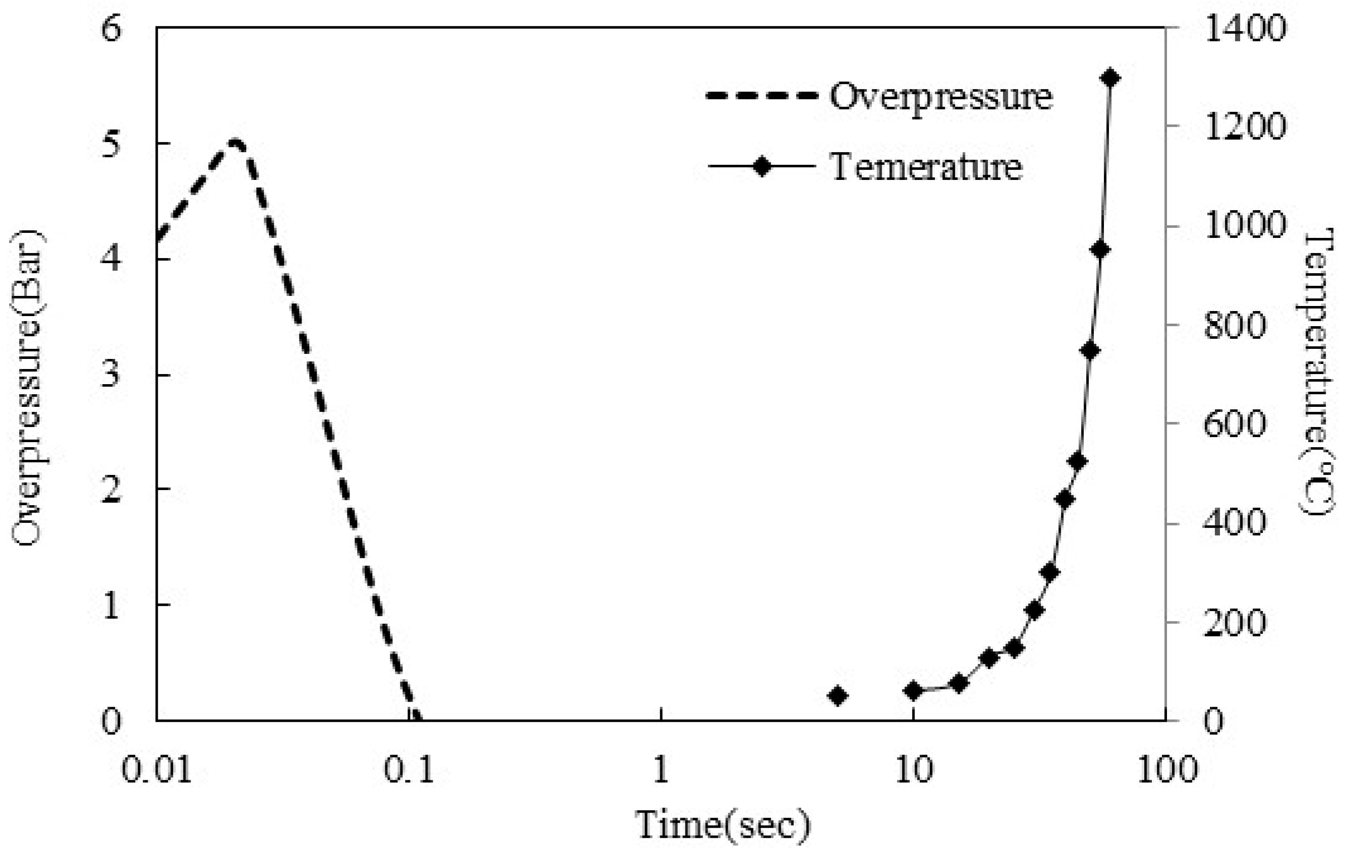
Additionally, ultra-fast fires in industrial complexes are often accompanied by overpressure. In the case of dust fires, overpressures of approximately 3 bar or more have been reported. Therefore, this study extended the time–pressure curve proposed by Kim et al. [
20] from 3 bar to 5 bar and conducted an analytical study accordingly (
Figure 2).
3. Ultra-Fast Fire Experiment and Analysis Method
3.1. Ultra-Fast Fire Scenario
In this study, the ultra-fast fire range was defined as a fire reaching 1 MW within 60 s and a maximum fire pressure of 5 bar. Since the standards for ultra-fast fires are undefined in Korea, the definition was based on the ultra-fast fire growth curve of the NFPA 92B [
22] fire-type growth curve (
Figure 1). NFPA is the world’s largest disaster prevention organization and serves as the foundation for fire codes in the United States, serving as an international standard for fire safety. Ultra-fast fires impose a combination of two types of loads: thermal loads from fire exposure and pressure loads generated by overpressure. As illustrated in
Figure 2, the overpressure develops and dissipates in a much shorter duration compared to the thermal load. The time–pressure curve used in this study also shows that the maximum pressure is reached in 0.02 s and then rapidly decreases. The time–temperature heating curve for 1 MW at 1 min is based on the 60 s temperature limit for reaching 1200 °C. At 0.02 s, when overpressure occurs, it corresponds to the onset of heating, and the temperature remains nearly equivalent to ambient levels (
Figure 3). Accordingly, for the protective block, the pressure load induced by overpressure is expected to occur first, followed by the thermal load arising from elevated temperature. To accurately reflect this sequence in the numerical analysis using LS-DYNA, the time–pressure and time–temperature heating curves were implemented such that the pressure was applied prior to the thermal load.
3.2. Ultra-Fast-Fire-Resistant Protective Block
The basic aim of the ultra-fast-fire-resistant protective block proposed in this paper is to manufacture it in a lightweight and simple form, analogous to sandwich panels, to enable easy installation and integration within existing industrial complexes. To leverage the advantages of sandwich panels, a similar form-factor configuration was adopted for the protective block. Its configuration was determined based on the experimental results of Kim et al. [
20], which sought to minimize the thickness of steel plates and glass wool, as well as to reduce the required amount of fire-resistant paint. The proposed sandwich panel-type protective block is composed of layers of fire-resistant paint, front and rear steel plates, and glass wool insulation. The material properties used in this study are listed in
Table 1. However, experiments by Kim et al. [
20] revealed that the fire-resistant paint detached during the overpressure test. Accordingly, the experimental plan for the ultra-fast fire resistance test was designed both to prevent such detachment and to determine the appropriate paint thickness. To achieve this, a minimum-thickness, fire-resistant paint detachment plate was installed in front of the impact-facing steel plate.
There are two primary reasons for maintaining a fixed spacing between fire-resistant paint detachment prevention plates. First, placing the anti-spalling plate in front of the steel faceplate protects the fire-resistant paint from direct impact. Second, due to the material characteristics of the paint, it expands when exposed to heat, which helps to reduce heat transfer to the rear side. Thus, fixed spacing was provided to accommodate thermal expansion of the paint.
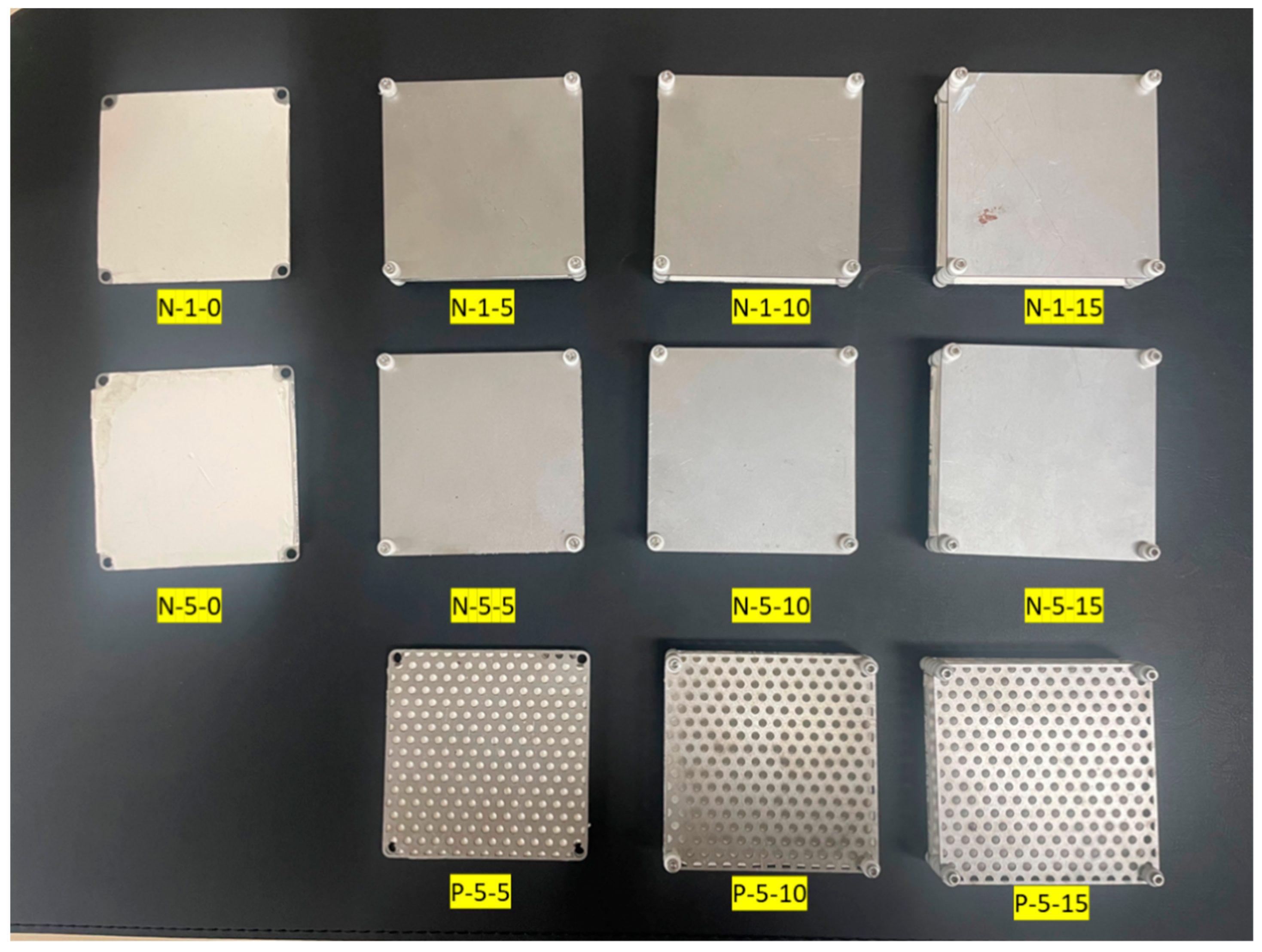
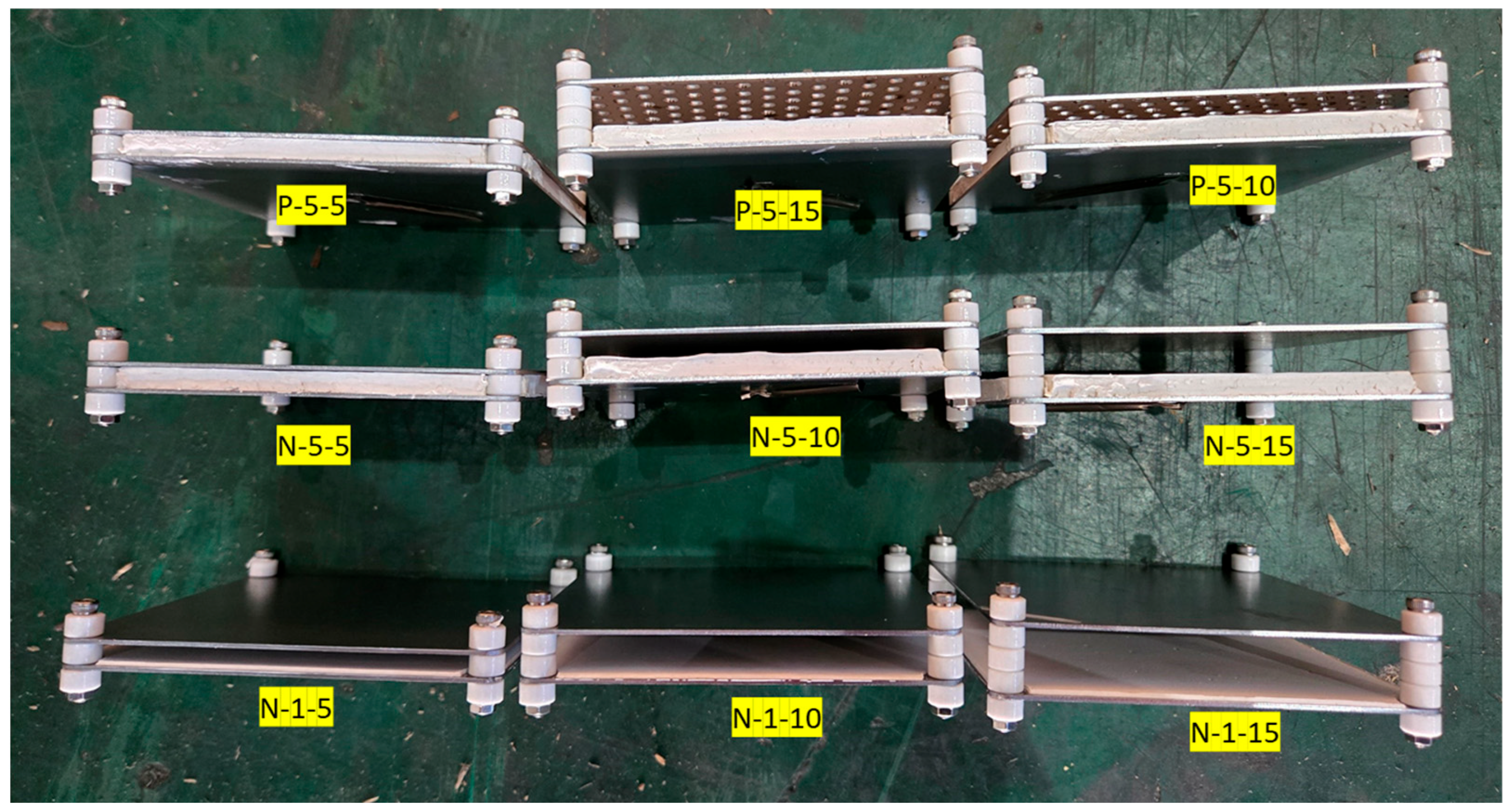
To further evaluate the effectiveness of this approach, especially in cases where no expansion space is available between the paint and the steel plate, two types of faceplates were tested: standard steel plates and perforated steel plates (
Table 2,
Figure 4 and
Figure 5). The perforated steel plates had holes with a diameter of 4 mm, and the spacing between perforations was kept constant.
3.3. Ultra-Fast Fire Experiment Method
The protective block test was conducted as a fire resistance performance evaluation simulating ultra-fast fire conditions. For this purpose, a time–temperature curve was developed based on the time–HRR curve, reaching a peak temperature of 1200 °C within 60 s (
Figure 2). A methane–oxygen torch burner system was employed to heat the specimen surface to 1200 °C within one minute, after which the oxygen supply was terminated.
The test specimens were fabricated with dimensions of 100 × 100 mm. During the test, K-type thermocouples were installed at two locations: at the center of the exposed front steel surface and at the center of the rear side of the front steel plate coated with fire-resistant paint.
The experimental variables for the ultra-fast fire protective blocks included the presence or absence of a fire-resistant paint detachment prevention plate, the thickness of the fire-resistant paint layer, and the expansion gap between the paint and the steel plate. The fire-resistant paint was applied in 1–2 mm layers, with each layer air-dried for 24 h before subsequent coatings were added.
3.4. Ultra-Fast Fire Analysis Model and Method
Simulating ultra-fast fires requires the consideration of both overpressure effects and rapid thermal loading. Because reproducing such conditions in real-scale experiments involves significant hazards, such experimental programs are necessarily limited. Therefore, in this study, LS-DYNA was employed to evaluate the performance of protective blocks under ultra-fast fire scenarios. To enhance the accuracy of the analysis, results from a jet fire experiment—used as a representative simulation of ultra-fast fire conditions—were incorporated.
In the numerical simulation, a uniformly distributed initial overpressure of 5 bar was applied to the specimen. Subsequently, a time–temperature heating curve was derived from measurements on the rear surface of the front steel plate obtained during the ultra-fast fire simulation experiment, where the specimen reached 1200 °C within 60 s at the material level (
Figure 6). The heating curve was defined by the peak temperature recorded during the test.
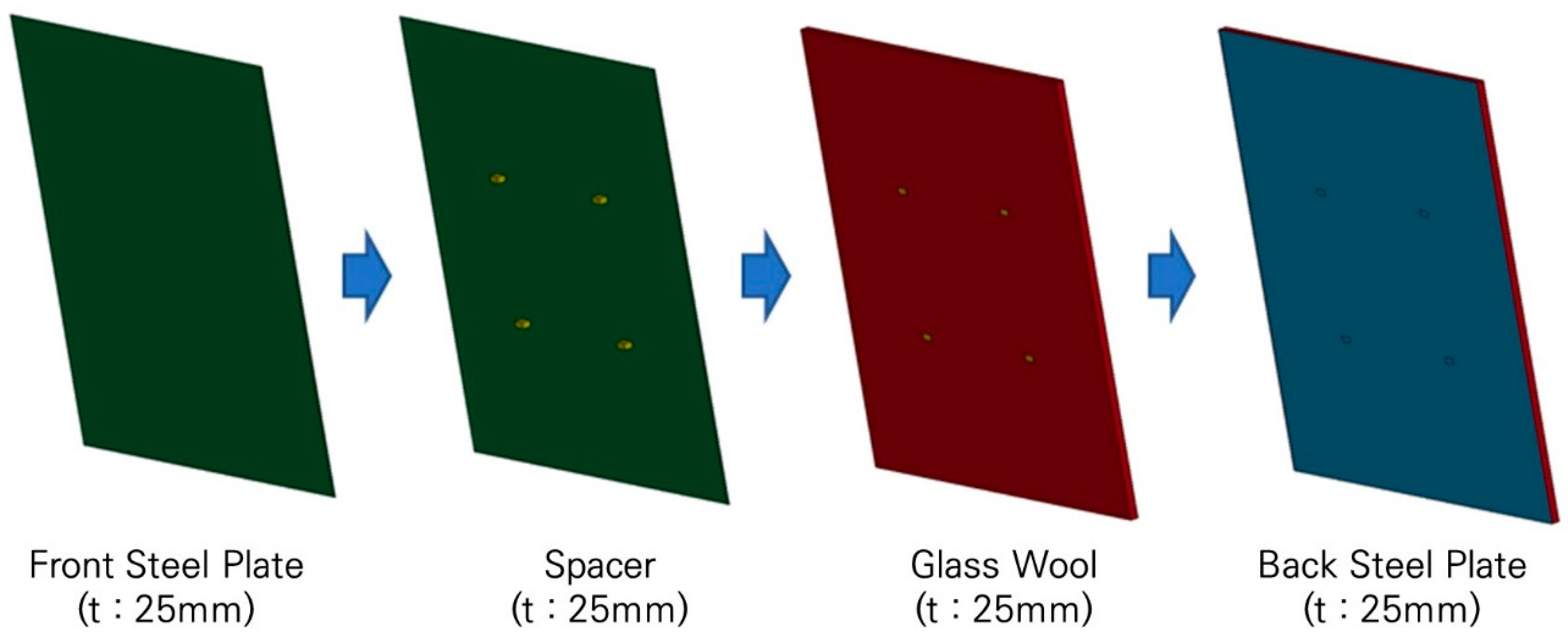
The protective block configuration used in the analysis (
Figure 7) consisted of a 2 mm front steel plate, a spacer, a 25 mm glass wool core, and a 2 mm back steel plate.
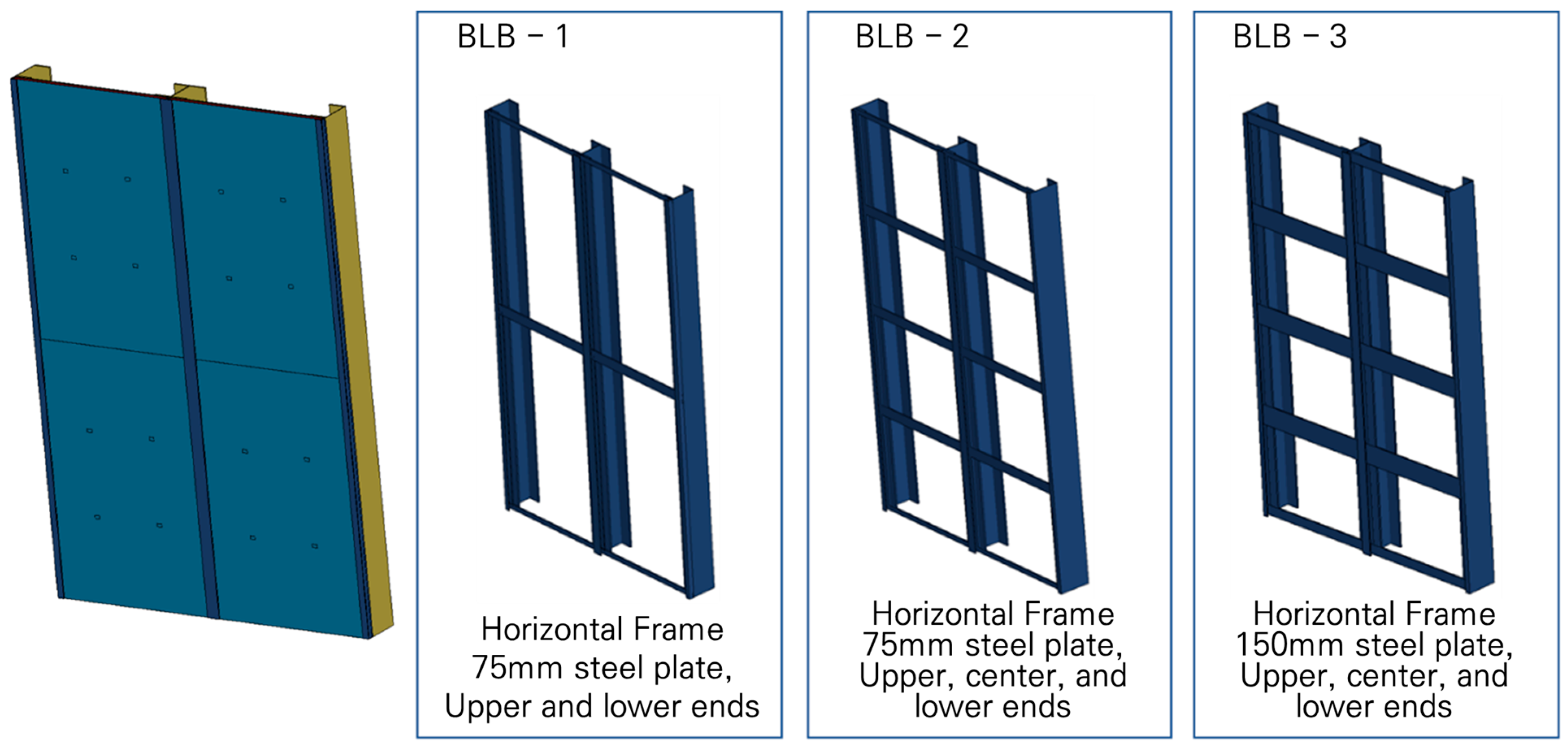
To ensure the overpressure-resistant performance of the protective block system, a structural support framework was introduced. For the vertical members, H-beams (200 mm × 200 mm) were employed, while for the horizontal members, the location and width of the steel plate installation were treated as variables (
Figure 6).
The primary objective of this analysis was to guarantee both resistance to overpressure and durability under ultra-fast fire conditions, which required adopting a structural system rather than relying solely on a single protective block.
The structural system model consisted of 4-unit blocks integrated into a supporting frame, as illustrated in
Figure 8.
The mesh size was set to 10 mm for both the blocks and the structural frame. For certain members where a 10 mm mesh could not be applied due to dimensional constraints, a finer mesh smaller than 10 mm was adopted. The boundary condition was defined such that the interfaces between the 4-unit blocks were kept in a separated state under the contact condition, while only the shortest ends of the structural frame were fixed as rigid.
The material models applied in the LS-DYNA ultra-fast fire analysis consisted of steel plates and glass wool. For the steel plates, the temperature-dependent variations in material properties were incorporated, as summarized in
Table 3. In contrast, the material properties of glass wool remained relatively stable across temperature ranges and exerted only a minor influence on mechanical performance; therefore, constant values were assigned, also presented in
Table 3.
4. Ultra-Fast Fire Experiment and Analysis Result
4.1. Ultra-Fast Fire Experiment Result
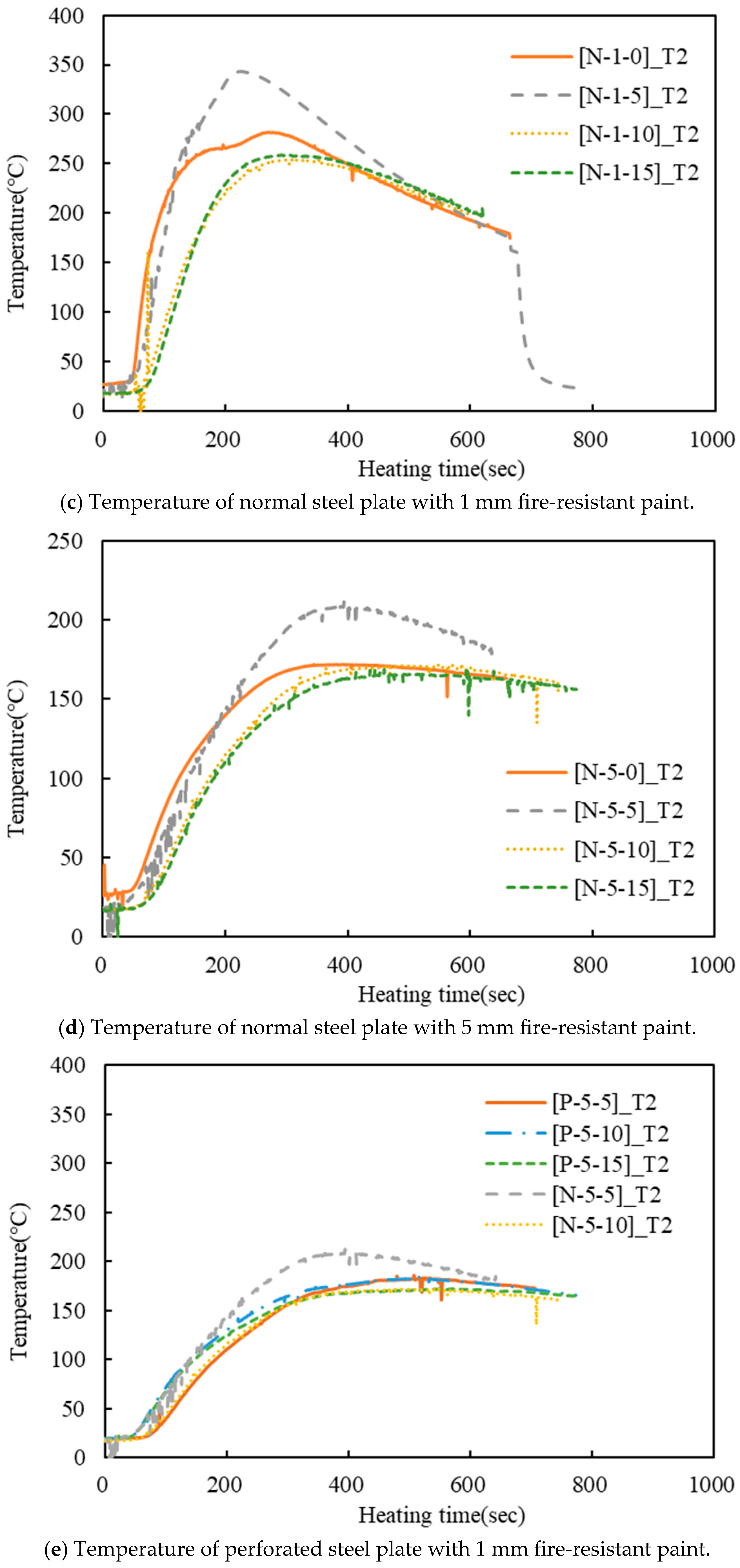
The fire resistance test results for the protective block indicated that the surface temperature reached 1200 °C within the first minute of testing and then dropped immediately once the oxygen supply to the torch burner was cut off (
Figure 9a). The temperature stabilized between 800 and 1000 °C for approximately 200 s before declining rapidly. This sustained high temperature is attributed to the thermal insulation effect of the expanded fire-resistant paint, which delayed heat dissipation by limiting internal heat transfer.
The insulation performance associated with fire-resistant paint thickness is illustrated in
Figure 9b. With a 1 mm coating, the maximum back-surface temperature rose to around 280 °C, whereas with a 5 mm coating, it was reduced to approximately 170 °C, representing a 110 °C difference. In addition, the temperature gradient decreased by nearly 60.71% when comparing the 5 mm thickness to the 1 mm thickness.
The effect of expansion space between the fire-resistant paint and the steel plate is presented in
Figure 9c,d. For both 1 mm and 5 mm paint applications, a 5 mm expansion space exhibited inferior performance compared to the 5 mm case without the anti-spalling plate. Similar performance was observed in both conditions, with the 10–15 mm expansion space delivering the most effective insulation. However, beyond 10 mm, additional expansion space did not yield significant improvements. Notably, the initial performance slope increased sharply from 0 to 5 mm but only gradually improved beyond 10 mm of paint thickness. Therefore, when using steel plates, regardless of paint thickness, a minimum expansion space of 10 mm is required for effective insulation.
As shown in
Figure 9e, the insulation performance of fire-resistant paint anti-spalling plates made of either solid steel or perforated steel was evaluated. The perforated steel plate exhibited superior performance, maintaining maximum back-surface temperatures within the range of 171–187 °C. Even with additional expansion space, the overall thermal response and temperature rise slope remained nearly identical. The specimen with 5 mm of fire-resistant paint applied directly onto the perforated steel plate, without expansion space, demonstrated the best fire resistance, reaching a maximum temperature equivalent to approximately 87.7% of that observed with the solid steel plate.
Furthermore, the N-5-10 specimen, which incorporated 5 mm of paint and a 10 mm expansion space on a solid steel plate, achieved 97.5% of the performance level of its perforated counterpart. These results indicate that, in the case of solid steel plates, effective fire resistance cannot be achieved without sufficient expansion space for the fire-resistant paint. In contrast, perforated steel plates provide inherent expansion voids through their perforations, thereby ensuring consistent performance even without additional spacing.
Among the perforated steel plate configurations, the 15 mm expansion space produced the best thermal insulation, with a maximum temperature of 171.5 °C. However, considering manufacturing feasibility and constructability, minimizing the expansion gap was determined to be more practical. Accordingly, this study proposed a protective block system optimized for ultra-fast fire conditions, with the anti-spalling plate constructed from perforated steel, a 5 mm coating of fire-resistant paint applied to the front plate, and block assembly performed without additional expansion space.
4.2. Ultra-Fast Fire Analysis Result
The overpressure resistance of the protective block system under ultra-fast fire conditions was evaluated by applying both the protective block and its supporting structural system. To assess the influence of horizontal frame size and placement, a case study analysis was conducted. The vertical frame utilized H-beams (200 mm × 200 mm).
For BLB-1, a 75 mm horizontal frame was positioned at the upper and lower ends of the unit protective blocks. The results indicated that BLB-1 failed before reaching maximum overpressure, as the horizontal frame was unable to withstand the applied load, leading to separation between the block edges and the frame (
Figure 10a).
For BLB-2, an additional 75 mm horizontal frame was installed at the center of the protective block. As shown in
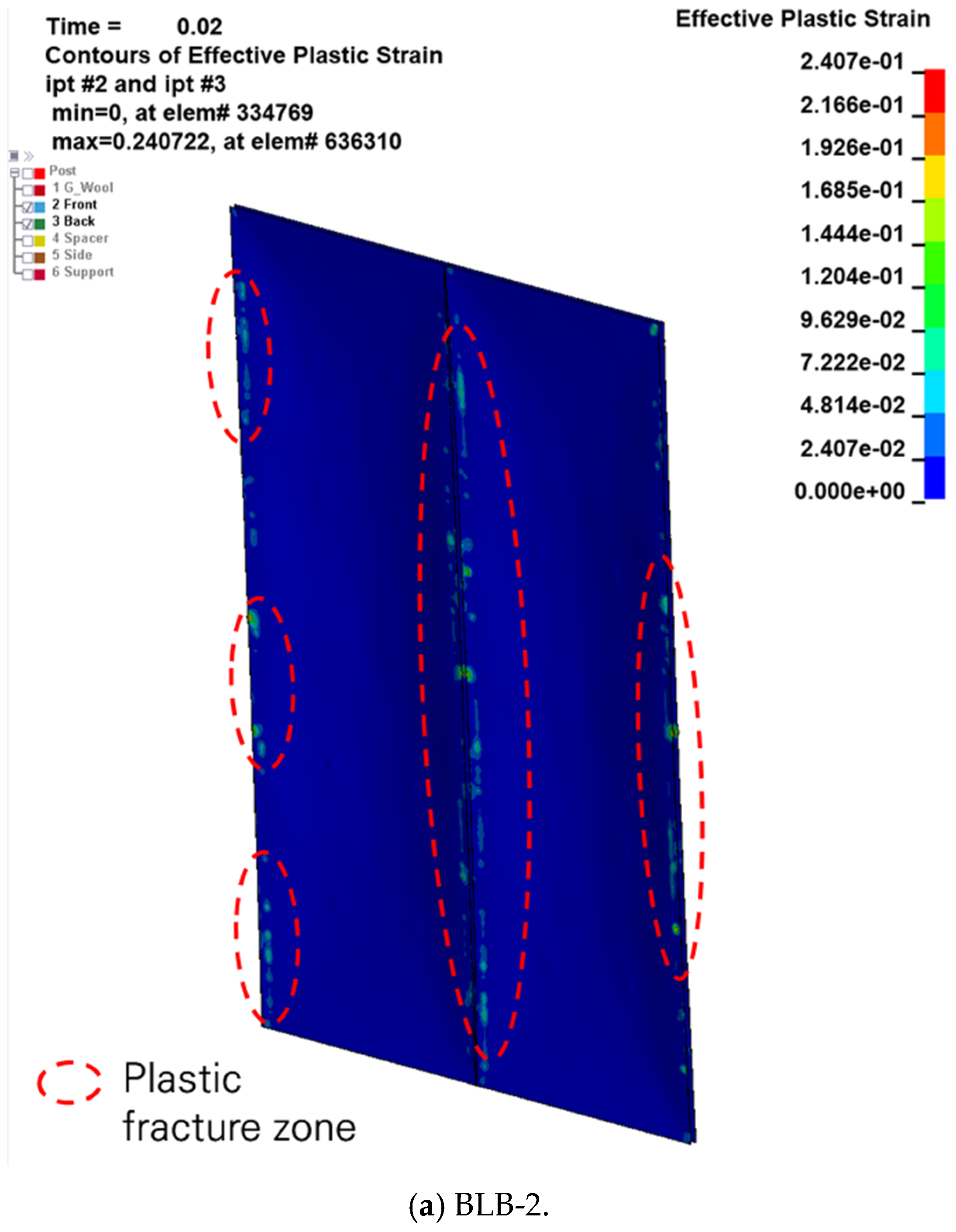
Figure 10b, the system maintained integrity up to 0.02 s, corresponding to the occurrence of maximum overpressure. The peak deflection reached approximately 92 mm (
Figure 11a), converging to ~68 mm after elastic recovery. Although the steel plate maintained overall continuity, the applied load induced a large plastic zone at the block edge under peak pressure (
Figure 12a). This outcome highlights the need for reinforcement to ensure both fire resistance and structural stability.
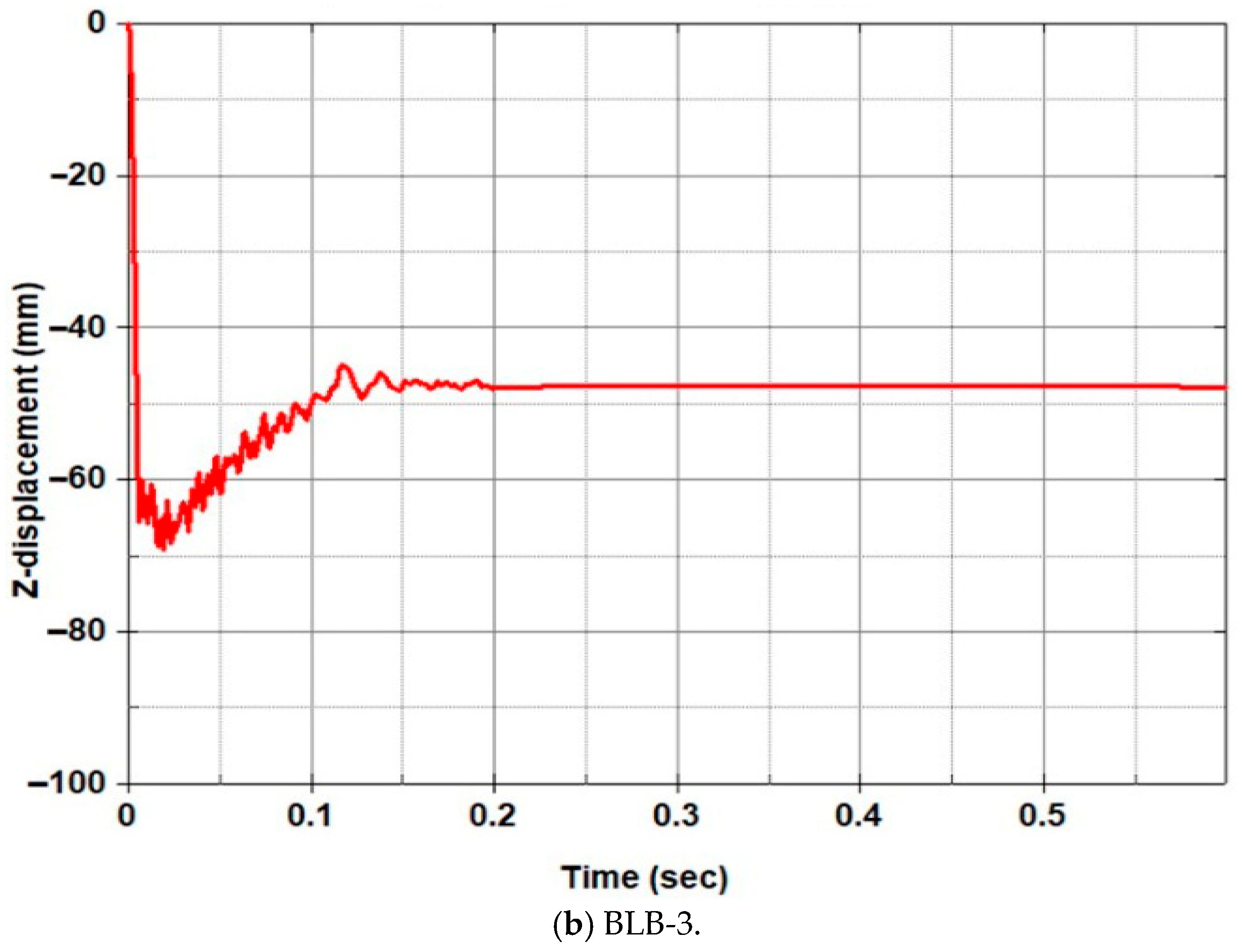
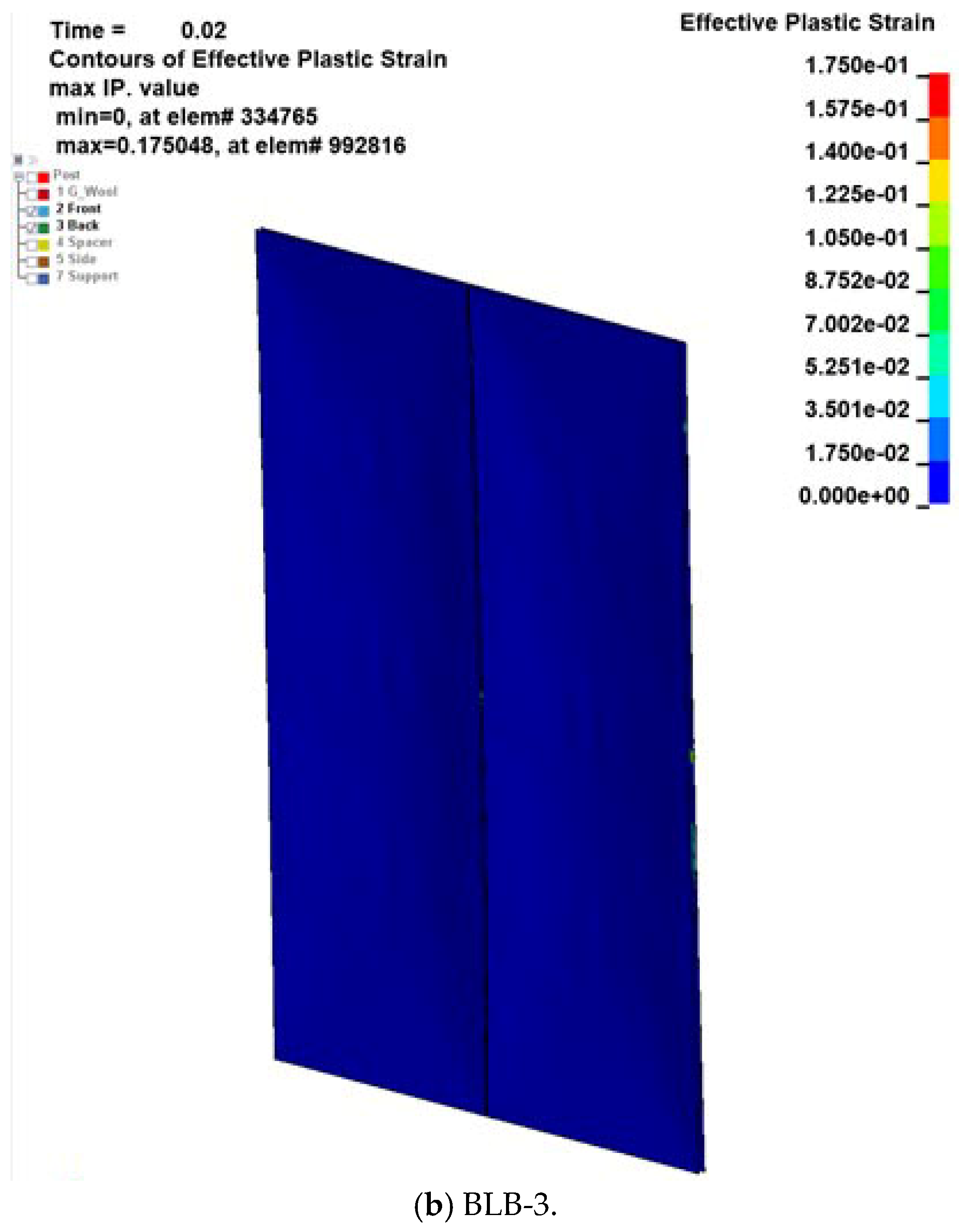
In BLB-3, the same support arrangement as BLB-2 was used, but the vertical width of the horizontal frame was increased by 150 mm. The analysis confirmed structural integrity under peak overpressure. At 0.02 s, the maximum deflection was ~70 mm (
Figure 10c and
Figure 11b), and elastic recovery reduced displacement to ~47 mm. Since no codified design standards currently exist for ultra-fast fires, this study adopted deflection limit states as the design criterion for fire-resistant steel members. A deflection limit of 50 mm was selected based on ISO 834-14 and EN 1363, which specify allowable deflections of L/20–30 [
9,
23,
24]. Given the member length (L = 1500 mm), the 50 mm limit was applied. Compared with BLB-2, elastic recovery performance showed minimal differences. However, as shown in
Figure 12b, the plastic zone was much less pronounced. It should be noted, however, that in the analysis, the ends were assumed to be fixed, so the overpressure acting on the protective blocks in an actual structure may be relatively lower than the simulated values.
Therefore, the results demonstrate that BLB-3 can reliably withstand an overpressure of 5 bar, representative of ultra-fast fire conditions.
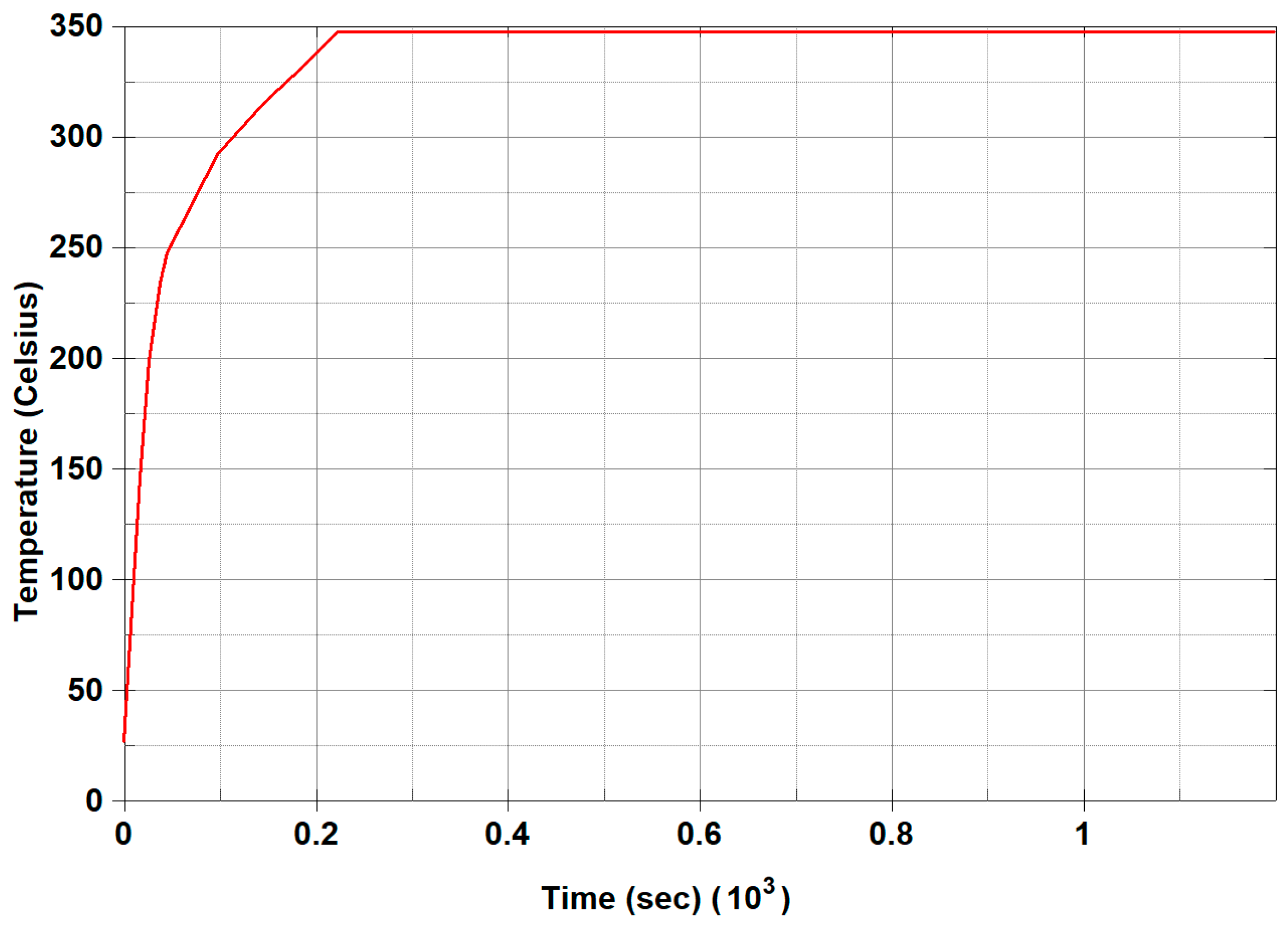
The analysis results for securing fire resistance performance against ultra-fast fires were obtained based on a single unit. In this case, the temperature–time curve was derived from the temperature measured at the front steel plate behind the fire-resistant coating, as shown in
Figure 6. The curve was modified to reflect that the temperature persisted up to 4000 s after reaching the maximum temperature, and the corresponding analysis was conducted accordingly. The temperature–time curve is presented in
Figure 13.
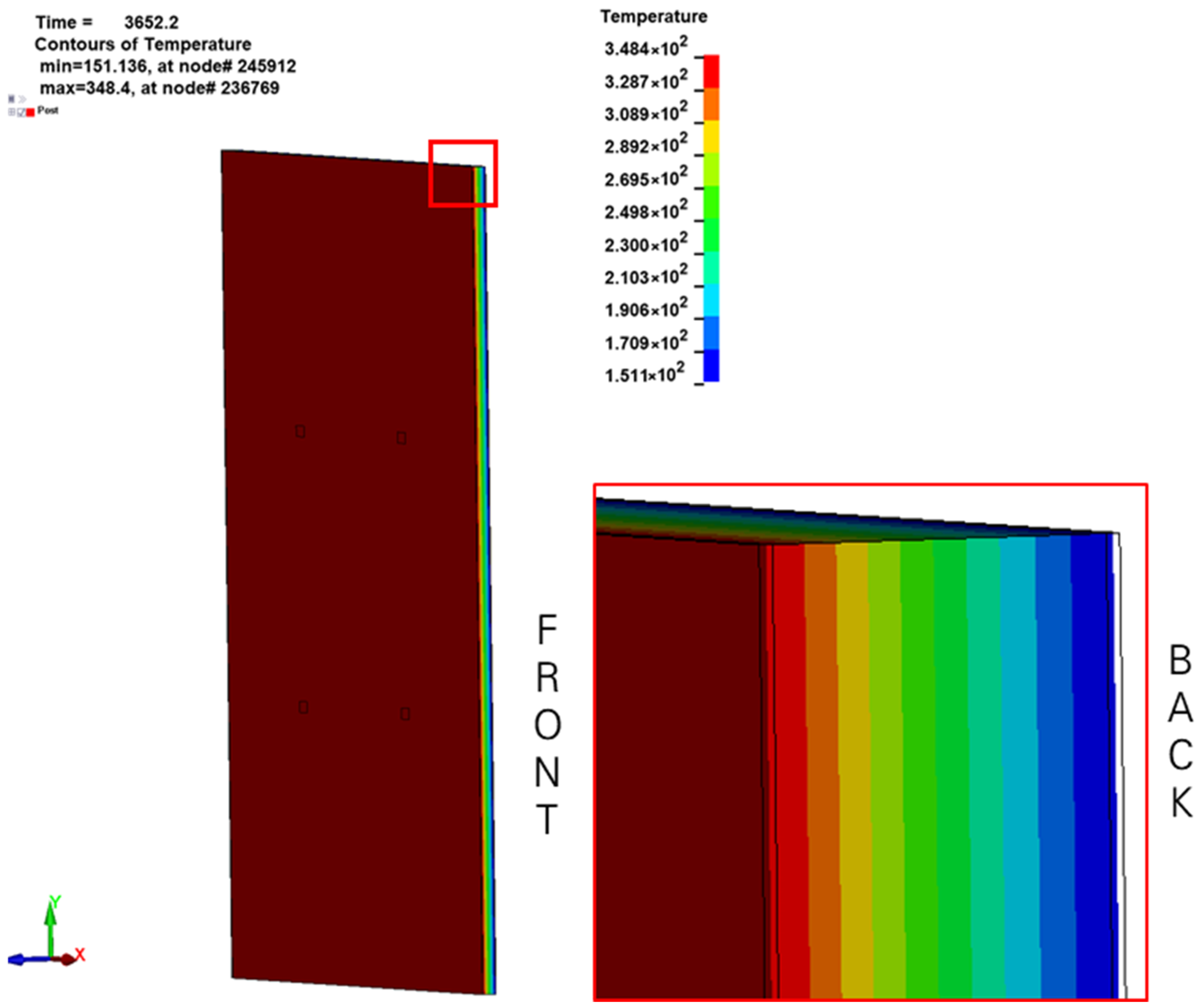
The analysis was conducted to examine the heat transfer process from the front steel plate, located behind the fire-resistant coating, to the rear steel plate. The results, obtained approximately one hour after the onset of heating, are shown in
Figure 14. The front steel plate temperature increased to about 350 °C, after which heat was transmitted through the glass wool insulation to the rear steel plate. Due to the insulation effect of the glass wool, the temperature decreased to around 250 °C at the central region and further reduced to approximately 151 °C at the rear steel plate.
The average temperature of the rear steel plate was represented as a time–temperature curve, as shown in
Figure 15. The curve indicates that the rear plate reached about 60 °C within 20 min after heating commenced and approximately 151 °C after one hour. Experimental results also showed that the maximum rear plate temperature reached about 170 °C, which was consistent with the numerical analysis. Therefore, it can be concluded that the BLB-3 configuration secures adequate resistance against both overpressure and thermal loads under ultra-fast fire conditions.
5. Conclusions
This study proposed a protective block configuration capable of responding to ultra-fast fires and examined the performance of the protective block structural system to protect against the overpressure associated with ultra-fast fires. To ensure the fire-resistant and protective performance of the protective block, experimental and analytical studies were conducted, leading to the following conclusions.
It was experimentally confirmed that when installing a fire-resistant paint anti-spalling plate, space must be secured for the fire-resistant paint to expand in order to secure performance capable of responding to ultra-fast fires.
For fire-resistant paint to respond to ultra-fast fires, the back steel plate surface temperature must reach up to 360 °C with a thickness of 2 mm, so it is recommended to secure a minimum thickness of 5 mm.
When using a normal steel plate as a fire-resistant paint anti-spalling plate, it was confirmed that an expansion space of at least 10 mm must be secured. In the case of perforated steel plate, it was confirmed that a separate expansion space is not necessary because the fire-resistant paint expands through the perforation.
If the front steel plate is made of a 1 mm perforated steel plate, 5 mm fire-resistant paint, and a 2 mm front steel plate, it is possible to respond with a maximum temperature of 200 °C or less based on the back steel plate even if an ultra-fast fire of 1 MW per minute occurs.
In order to protect against overpressure of 5 bar accompanying ultra-fast fire, the structural system requires vertical frames of at least 200 × 200 H-beams and horizontal frames of 75 mm at the top, bottom, and middle.
If you want to secure structural integrity by considering the amount of deflection that occurs after overpressure protection, it is recommended that the vertical width of the horizontal frame be at least 150 mm.
The heat load analysis results indicated that the maximum temperature of the rear steel plate reached approximately 151 °C after one hour. This result is in good agreement with the ultra-fast fire simulation experiment, where the maximum temperature was measured at approximately 170 °C. Therefore, it can be concluded that the protective block proposed in this study is capable of providing effective resistance against ultra-fast fire conditions.
The results of this study show that for a protective block to withstand an ultra-fast fire with a 1 MW per minute rate, it must be constructed with a 1 mm front fire-resistant paint anti-spalling plate, a 5 mm fire-resistant paint coating, a 2 mm front steel plate, 250 mm glass wool, and a 2 mm back steel plate. Furthermore, to protect against overpressure exceeding 5 bar associated with ultra-fast fires, the protective block structural system must be equipped with at least 200 × 200 vertical H-beams and 150 mm horizontal frames at the top, bottom, and middle.
This study establishes quantitative criteria for ultra-fast fires and provides a basis for reliable analysis and evaluation, thereby laying the groundwork for the advancement of predictive modeling and assessment technologies under extreme conditions. However, as the present work was limited to securing overpressure resistance through the integration of protective blocks and structural systems, further research is required for practical application in industrial complexes, particularly on additional design aspects such as entrances, openings, and other architectural components.
Author Contributions
W.-W.K. performed Conceptualization, Investigation, Writing—original draft. G.-C.C., H.-Y.K. and S.-W.K. perfomed Investigation and Data curation. J.-H.M. performed Investigation and Validation. All authors have read and agreed to the published version of the manuscript.
Funding
This paper was supported by a grant from the project ‘Development of Ultra-Fast Fire Prediction·Control·Response Technology in Industrial Complex (3/3)’, which was funded by the Korea Institute of Civil Engineering and Building Technology (KICT).
Data Availability Statement
The original contributions presented in this study are included in the article. Further inquiries can be directed to the corresponding author.
Conflicts of Interest
The authors declare that they have no competing interests.
Abbreviations and Technical Terms
The following abbreviations are used in this manuscript:
| HRR | Heat release rate |
| NFPA | National Fire Protection Association |
| Ultra-fast fire | Fire with rapid heat release and overpressure generation |
| Protective block | Structural block designed to resist ultra-fast fire and overpressure |
| Overpressure | Pressure increase caused by rapid combustion or dust fire |
| Glass wool | Fibrous insulation material used in protective blocks for thermal resistance |
| Deflection limit | Maximum allowable bending or displacement of structural members |
| Structural system | Frame including protective blocks and supporting members (horizontal and vertical frames) |
| Expansion space | Gap provided for thermal expansion of fire-resistant paint |
| Elastic recovery | Structural displacement recovery due to elasticity after load removal |
References
- Kang, D.H.; Kang, D.H.; Shin, D.H.; Kim, H.J. An Analysis of Factors Influencing Insulation Performance of Inorganic Autoclaved Lightweight Concrete Sandwich Wall Panels Using Shear Connectors. J. Archit. Inst. Korea Struct. Constr. 2018, 34, 79–87. [Google Scholar] [CrossRef]
- Moon, J.W.; Chae, C.U. A Study on the Flame Retardation of Polystyrene Foam (EPS) in Sandwich Panels. J. Archit. Inst. Korea 2021, 37, 211–218. [Google Scholar] [CrossRef]
- Davies, J.M. Sandwich Panels. Thin-Walled Struct. 1993, 16, 179–198. [Google Scholar] [CrossRef]
- Lee, J.C.; Lee, S.H.; Song, H. Composition Methods for Fire Resistance of The Glass Wool Sandwich Panel Wall without Girth Reinforcement. J. Archit. Inst. Korea Struct. Constr. 2007, 23, 85–92. [Google Scholar]
- Wi, S.H.; Yang, S.W.; Yun, B.Y.; Kang, Y.J.; Kim, S.M. Fire retardant performance, toxicity and combustion characteristics, and numerical evaluation of core materials for sandwich panels. Environ. Pollut. 2022, 312, 120067. [Google Scholar] [CrossRef] [PubMed]
- Kim, Y.U.; Yang, S.W.; Wi, S.H.; Kim, S.M. Evaluation of heterogeneous core sandwich panels for energy efficiency and fire safety in warehouse buildings. Appl. Therm. Eng. 2024, 249, 123455. [Google Scholar] [CrossRef]
- Gao, W.; Yu, J.; Zhang, X.; Li, J.; Wang, B. Characteristics of vented nano-polymethyl methacrylate dust explosions. Powder Technol. 2015, 283, 406–414. [Google Scholar] [CrossRef]
- Li, Q.Z.; Lin, B.Q.; Li, W.X.; Zhai, C.; Zhu, C.J. Explosion characteristics of nano-aluminum powder–air mixtures in 20 L spherical vessels. Powder Technol. 2011, 212, 303–309. [Google Scholar] [CrossRef]
- Chaturvedi, S.; Vedrtnam, A.; Youssef, M.A.; Palou, M.T.; Barluenga, G.; Kalauni, K. Fire-Resistance Testing Procedures for Construction Elements—A Review. Fire 2023, 6, 5. [Google Scholar] [CrossRef]
- Zhou, R.; Chen, Z.; Fan, Y.; Yu, Z.; Qian, J.; Jiang, J. Fire Spread Characteristics of Metal-Polyethylene Sandwich Panels. Buildings 2021, 11, 396. [Google Scholar] [CrossRef]
- Jiang, H.; Xie, L.; Chang, F.; Cao, Y.; Guo, Z. Study on the Composite Performance of Sandwich Wall Panels with SGCCs. Buildings 2025, 15, 65. [Google Scholar] [CrossRef]
- Studziński, R.; Gajewski, T.; Malendowski, M.; Sumelka, W.; Al-Rifaie, H.; Peksa, P.; Sielicki, P.W. Blast Test and Failure Mecha-nisms of Soft-Core Sandwich Panels for Storage Halls Applications. Materials 2021, 14, 70. [Google Scholar] [CrossRef]
- Liu, C.; Liu, J.; Wei, J.; Xu, S.; Su, Y. Parametric Study on Contact Explosion Resistance of Steel Wire Mesh Reinforced Geopolymer Based Ultra-High Performance Concrete Slabs Using Calibrated Continuous Surface Cap Model. Buildings 2022, 12, 2010. [Google Scholar] [CrossRef]
- Liu, K.; Liu, H.; Li, Y.; Wang, Z.; Wang, J. A Simplified Method for Evaluating the Dynamic Response of the Metal Sandwich Structure under Explosion Load. Metals 2022, 12, 1933. [Google Scholar] [CrossRef]
- Gomes, G.d.J.; Lúcio, V.J.d.G.; Cismaşiu, C.; Mingote, J.L. Experimental Validation and Numerical Analysis of a High-Performance Blast Energy-Absorbing System for Building Structures. Buildings 2023, 13, 601. [Google Scholar] [CrossRef]
- Kim, H.J.; Lilley, D.G. Heat release rates of burning items in fires. In Proceedings of the 30th Aerospace Sciences Meeting & Exhibit, Reno, NV, USA, 10–13 January 2000. [Google Scholar]
- Cheong, M.K.; Cheong, W.O.; Leong, K.W.; Lemaire, A.D.; Noordijk, L.M. Heat release rate of heavy goods vehicle fire in tunnels. Fire Technol. 2014, 50, 249–266. [Google Scholar] [CrossRef]
- Yun, H.S.; Nam, D.G.; Hwang, C.H. An experimental study on the fire spread rate and separation distance between facing stores in passage-type traditional markets. Energies 2020, 13, 4458. [Google Scholar] [CrossRef]
- Regan, J.W. Heat release rate characterization of NFPA 1403 compliant training fuels. Fire Technol. 2021, 57, 1847–1867. [Google Scholar] [CrossRef]
- Kim, W.W.; Yoon, U.G.; Kim, H.S.; Choe, G.C.; Moon, J.H.; Shin, H.S.; Kim, S.W. Experimental Study on the Applicability of Fire Resistant protective Block to Respond to Ultra-fast Fire Accompanied. J. Korean Recycl. Constr. Resour. Inst. 2024, 12, 420–428. [Google Scholar] [CrossRef]
- Kim, W.W.; Choe, G.C.; Moon, J.H.; Shin, H.S.; Kim, H.Y.; Kim, S.W. Analysis of structural system for fire resistant protective panel to respond ultra-fast fire accompanied by overpressure. J. Korean Recycl. Constr. Resour. Inst. 2025, 13, 153–160. [Google Scholar] [CrossRef]
- NFPA 92B; Standard for Smoke Management Systems in Malls, Atria, and Large Spaces. The National Fire Protection Association: Quincy, MA, USA, 2009.
- ISO 834-14:2019; Fire-Resistance Tests. International Organization for Standardization: Geneva, Switzerland, 2019.
- EN 1363-1:2012; Fire Resistance Tests. European Committee for Standardization: Brussels, Belgium, 2012.
| Disclaimer/Publisher’s Note: The statements, opinions and data contained in all publications are solely those of the individual author(s) and contributor(s) and not of MDPI and/or the editor(s). MDPI and/or the editor(s) disclaim responsibility for any injury to people or property resulting from any ideas, methods, instructions or products referred to in the content. |
© 2025 by the authors. Licensee MDPI, Basel, Switzerland. This article is an open access article distributed under the terms and conditions of the Creative Commons Attribution (CC BY) license (https://creativecommons.org/licenses/by/4.0/).


