Abstract
Cracks in concrete dam tunnels compromise structural safety, watertightness, and durability, while conventional repair materials such as epoxy and cement impose environmental burdens. This study investigates biomineralization methods, namely Microbially Induced Calcium Carbonate Precipitation (MICP) and Enzyme-Induced Carbonate Precipitation (EICP), for repairing fine cracks in a large hydropower dam tunnel. Laboratory tests and field applications were conducted by injecting urea–calcium solutions with Sporosarcina pasteurii for MICP and soybean-derived urease for EICP, applied twice daily over three days. Both techniques achieved effective sealing, with precipitation efficiencies of 93.75% for MICP and 84.17% for EICP. XRD analysis revealed that MICP produced a mixture of vaterite and calcite, reflecting biologically influenced crystallization, whereas EICP yielded predominantly calcite, the thermodynamically stable phase. SEM confirmed that MICP generated irregular layered clusters shaped by microbial activity, while EICP formed smoother spherical and more uniform deposits under enzyme-driven conditions. The results demonstrate that MICP provides higher efficiency and localized nucleation control, while EICP offers faster kinetics and more uniform deposition. Both methods present eco-friendly and field-applicable alternatives to conventional repair, combining technical performance with environmental sustainability for hydraulic infrastructure maintenance.
1. Introduction
Cracks in dam tunnels represent more than simply superficial fractures, as they could potentially indicate hidden problems in the structure that could jeopardize the entire hydraulic system if left unattended [1,2,3]. These tunnels are essential for water transport, pressure relief, and drainage. They also undergo water pressure cycling, chemical exposure, thermal cycling, and the natural aging of structural materials. Over time these stressors can cause cracks in the tunnel linings, especially in cement-based materials. As large-scale reinforced concrete (RC) structures that serve in aquatic environments for long periods, dams are susceptible to corrosion of the internal steel bars. This corrosion is primarily caused by factors such as chloride ion penetration from water and wet–dry cycles. The volume expansion of corrosion products—which can reach two to six times the volume of the original steel bars—generates sustained tensile stress inside the dam’s concrete. This stress ultimately induces surface and internal cracks in the dam, seriously endangering the structural safety and service life of the dam [3,4,5]. The consequences of ignoring these cracks are very serious [6,7,8,9,10]. Water penetration through cracks can accelerate both internal erosion and corrosion of steel reinforcement, resulting in weakening the structural integrity of the tunnel. In extreme cases this can cause a significant collapse risk or shorten its life. Furthermore, cracks provide pathways for undesirable water movement, which can lead to energy loss, sediment transport, and even environmental degradation downstream [11,12,13,14]. Various conventional repair methods have been developed to address these issues. Cement-based repair mortars are used for larger surface cracks and epoxy resins and polymer injections for smaller cracks and to make structures watertight. While effective at sealing cracks and improving short-term performance, many of these products have sustainability concerns. Epoxy resins are based on petroleum, which make them Volatile Organic Compounds (VOCs) during application. More importantly, the manufacturing and application of such conventional repair materials significantly contribute to the global carbon footprint, and thus, due to environmental concerns, limiting their use in large-scale applications and reusability in sensitive ecosystems [15,16,17,18,19,20,21]. This raises a high demand for more sustainable maintenance practices in exploring eco-friendly alternatives for crack repair methods that align with long-term durability and environmental protection.
Dam service tunnels are critical for hydropower operations, ensuring water transport, drainage, and pressure relief. However, harsh conditions such as water pressure cycling, temperature fluctuations, and chemical exposure lead to cracking in cementitious linings, compromising structural integrity and hydraulic efficiency. The reliable repair of these cracks is essential to maintaining the safety and functionality of such critical infrastructure, highlighting the need for sustainable and durable solutions.
In recent years, the global push toward sustainability and the reduction in environmentally harmful practices have highlighted the limitations of conventional repair methods. Traditional materials like epoxy and cement not only possess significant carbon footprints but also pose challenges in terms of long-term compatibility and potential toxicity when used in sensitive environments. This research contributes to addressing these challenges by providing a sustainable alternative that leverages naturally occurring biomineralization processes. With MICP and EICP, it is possible to achieve effective crack repair with a considerably lower environmental impact, aligning the methods with modern sustainability goals and green engineering principles.
As the need for sustainable infrastructure maintenance grows, bio-based solutions like Microbially Induced Calcium Carbonate Precipitation (MICP) and Enzyme-Induced Calcium Carbonate Precipitation (EICP) are receiving attention as alternatives to traditional crack repair materials [22,23,24]. Both methods aim to seal cracks by inducing in situ formation of calcium carbonate (CaCO3), a natural mineral that restores structure. MICP uses ureolytic bacteria to obtain urease, an enzyme that breaks down urea into carbonate ions [25]:
CO(NH2)2 + H2O → 2NH4+ + CO32−
Then the carbonate ions interact with surrounding calcium ions to precipitate calcium carbonate [25]:
CO32− + Ca2+ → CaCO3 ↓
The EICP method follows the same chemical pathway; however the bacteria are replaced with the urease enzyme. This simplifies the process and eliminates concerns about bacterial survival or environmental impact. Both methods use mild, non-toxic ingredients and produce minimal waste, a more eco-friendly solution than epoxy resins or cement/polymer-based mortars. By using natural mineralization, MICP and EICP are sustainable ways to repair cracks with minimal ecological disturbance [26,27].
MICP has been employed in different studies to repair cracks of various widths in cement-based specimens under different conditions. For instance, Choi et al. reported that cracks up to 0.52 mm could be fully sealed within a week using alternating bacterial and cementation solutions [28]. Sun et al. improved MICP performance in alkaline environments by supplementing it with glucose, obtaining over 79% surface sealing and moderate recovery in strength for relatively wider cracks [29]. Simple application approaches of MICP, like drop-wise treatment over 20 days, have also shown up to 85% sealing and strength regain [30]. Studies at low temperatures and with different bacteria strains further support MICP’s versatility, though tensile strength recovery remains limited in some cases [31]. Injection and diffusion methods have also proven effective for enhancing durability and water resistance [32]. EICP has also shown promise for crack sealing. Dakhane et al. reported that a low-concentration urease–urea–calcium solution produced uniform CaCO3 precipitation and improved flexural strength [33]. EICP treatments using soybean-derived enzymes helped heal fire-damaged concrete [34], while vacuum-assisted methods significantly boosted repair performance in micro-cracked specimens [35]. Yuan et al. studied EICP with chitosan as an additive to treat structural cracks up to 2 mm in tunnels, enhancing sealing and durability of repair objects for time periods over three months [36]. Other studies demonstrated that frequent EICP applications, with various fillers, can effectively restore strength and permeability, especially in cracks under 0.5 mm [37]. Furthermore, using fillers like fibers for wider cracks (up to 2 mm) can effectively restore structural integrity [38].
Microorganisms utilized in MICP for concrete crack repair are primarily classified into bacteria and fungi. Bacteria can be further divided by metabolic pathway into autotrophic types (e.g., methane-oxidizing Methylocystis parvus and photosynthetic cyanobacteria) and heterotrophic types, including ureolytic (Sporosarcina pasteurii), organic compound-converting (Bacillus subtilis), CO2-absorbing (Bacillus mucilaginus), sulfate-reducing (Desulfovibrio vulgaris), and denitrifying (Pseudomonas aeruginosa) strains. Fungi such as Cladosporium herbarum and Fusarium oxysporum show high alkalinity tolerance, and their hyphae act as nucleation sites for CaCO3. Key enzymes are urease, which hydrolyzes urea to carbonate but releases ammonia, and carbonic anhydrase, which hydrates CO2 to bicarbonate under alkaline conditions, enhancing CaCO3 precipitation without ammonia by-products [39,40].
This article describes the use of calcium carbonate precipitation methods MICP and EICP for biological repair of cracks in case study dam tunnels situated in China. This work started with assessment of the tunnel state before repair, supported by a full photographic record of the condition of the dam tunnel, including the positioning and size of the cracks. After that the repair process took place, where MICP and EICP were applied by grounding. Consequently, the precipitated calcium carbonate inside the cracks was evaluated in terms of crystallography and morphology, providing the material characteristics. In general, all the targeted cracks were treated effectively with no further leakage of water.
2. Crack State of the Tunnel Subjected to Repair
Concrete dams are subjected to constant external stresses and the aging process, both of which contribute to the cracking of structural components. While relatively small surface cracks may seem harmless, they allow water and other substances to start penetrating the member, accelerating the corrosion of the reinforcement and concrete deterioration. In extreme situations, such untreated small cracks can create pathways that could affect the integrity of the dam. Internal tunnels in dams are an inseparable part of the complex, which are used for personnel access, transporting equipment, and maintenance. These tunnels have developed various cracks over time due to stresses from both inside and outside the dam. Inspections have revealed interconnected fine cracks with different orientations: horizontal along construction joints; vertical due to tensile stresses; and diagonal due to shear forces. The tunnel environment during repair was stable, with temperatures of 20–22 °C, a relative humidity of 59–62%, and a measured pH of 9.5. The cracks treated in this study were between 0.1 and 0.3 mm wide and often extended more than 10 cm along tunnel surfaces. Although they are not always obvious at first, these cracks gradually allow water to get in and increase the risk of structure damage. Examples of detailed crack images in the tunnels are shown in Figure 1.
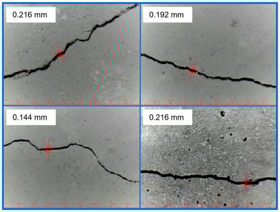
Figure 1.
Detailed crack view in the dam’s tunnel.
3. Repair Solution Preparation and Laboratory Tests
3.1. Preparation of Repair Solutions
In the case of the MICP solution, a Gram-positive ureolytic Sporosarcina pasteurii bacteria was chosen, as it is well known for precipitation of calcium carbonate in the presence of urea and a calcium source [41]. The fundamental biochemical mechanism by which Sporosarcina pasteurii facilitates calcium carbonate precipitation in the MICP process is as follows: Sporosarcina pasteurii causes calcium carbonate precipitation in MICP through its urease enzyme activity. The urease breaks down urea into ammonium and carbonate ions, which increases the local pH. This alkaline environment causes the calcium ions in the surrounding solution to become supersaturated and nucleate and grow calcium carbonate crystals on and around the bacterial cell surface, binding the material together. The bacterial culture medium was prepared by putting yeast extract, ammonium chloride, manganese sulfate, and nickel chloride into deionized water and mixing them at room temperature [40,42]. After pH adjustment, the solution was sterilized in sealed flasks. Under sterile conditions, a small amount of active bacterial culture was introduced to the culture medium after the flasks were cooled and exposed to UV light to reduce possible contamination. The flasks were incubated and stored in a shaker until the bacteria solution achieved sufficient levels of turbidity. Before conducting the experiment, the bacterial concentration was measured. The optical density (OD600) value was determined using the turbidimetric method, which measures the light intensity of suspended substances in the bacterial solution to determine the concentration of the bacterial solution. After the bacteria were cultured for 24 h, they were detected using a spectrophotometer, and the OD600 value was 2.88, indicating that the bacteria were in a growth state with a relatively high concentration. The spectrophotometer was manufactured by Shanghai Yuefeng Instrument and Meter Co., Ltd. (Shanghai, China), with the model number 721. The flow chart of bacterial preparation is shown in Figure 2. In the EICP approach, urease was extracted from soybeans (Glycine max) [43]. The dried beans were milled into a fine powder and sieved through a 0.2 mm mesh to obtain uniformity by a multifunctional crusher. The crusher was manufactured by Shenzhen Elsa Technology Co., Ltd. (Shenzhen, China), with the model number 1000A and a crushing fineness of 70–300 mesh. Milling was performed using a multifunctional crusher, with a crushing fineness of 70–300 mesh—i.e., soybeans were ground into soybean powder with a particle size ranging from 0.085 mm to 0.36 mm. Consequently, the soybean powder was mixed with deionized water in a ratio of 100 g/L, based on a study conducted by Gao et al. [43], and stirred for 30 min to facilitate enzyme release. The mixture was then refrigerated at 4 °C for over 12 h to allow urease diffusion while preserving enzyme activity. Afterward, it was centrifuged and filtered to obtain a clear urease-rich extract. The flow chart of plant urease extraction is shown in Figure 3. For both MICP and EICP treatments, a cementation solution containing urea and calcium chloride (1 M each) was prepared. The ratio of bacteria/urease to the cementation solution for the MICP or EICP method was in proportion of 1:1, mixed together prior to its application.
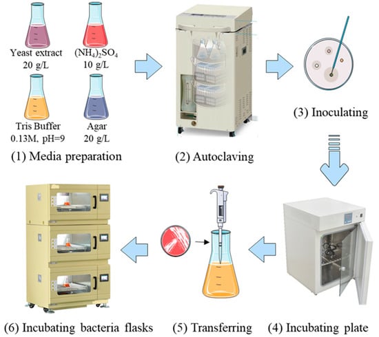
Figure 2.
Schematic illustration of bacterial culture [44].
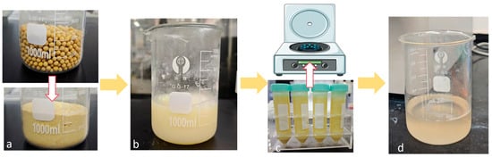
Figure 3.
Schematic diagram of plant urease extraction: (a) grind soybeans into powder; (b) mix soybean powder with deionized water thoroughly and store the mixture at 4 °C for 12 h; (c) centrifuge the mixed solution; and (d) collect the soybean urease solution.
3.2. Laboratory Tests
Laboratory investigations preceded on-site application, utilizing a dropping method [45] to simulate biomineralization crack repair. Based on preliminary preparation and experiments, a peristaltic pump was selected for the experiment using the modified drip method. The electric pump used is from Shanghai Yanshao Technology Co., Ltd. (Shanghai, China), with the model number LP01-3-B1*3. It has a maximum power consumption of 48 watts per hour. One laboratory drip device requires two such peristaltic pumps; however, the pumps do not operate at maximum power continuously during actual use, meaning that the total power consumption of one drip device does not exceed 96 watts per hour. The device occupies a floor space of 0.1 m2 and is height-adjustable, with an adjustment range of 1.1 m to 1.9 m. Solution bottles and electric pumps are either suspended or placed on infusion stands, and the solution bottles have a capacity of 500 mL, as shown in the experimental device setup in Figure 4. During subsequent batch experiments, electric pumps were stacked to save space, as shown in Figure 5.
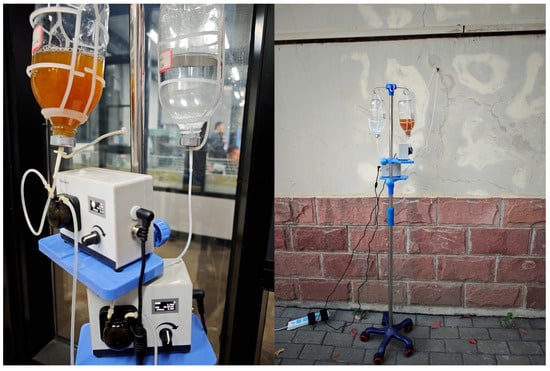
Figure 4.
Experimental device setup.
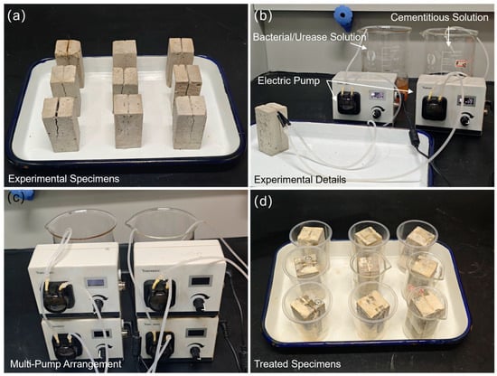
Figure 5.
Repair of specimen cracks by laboratory dropping method: (a) experimental specimens with cracks produced by splitting loading; (b) test setup; (c) multi-pump arrangements; and (d) healed specimens.
Cement mortar specimens (33 × 33 × 70 mm) were fabricated, and artificial cracks mimicking field morphology were induced via fracturing, as shown in the experimental specimen in Figure 5a. After assembling the dropping device, the bacterial solution (or urease solution) and cementitious solution were, respectively, loaded into their corresponding containers. The solutions were injected into the cracks via electric pumps, following the procedure illustrated in the experimental details of Figure 5b. Based on experimental experience, the parameters of the electric pump were set such that 5 mL of each solution was dripped into the crack every three minutes. Meanwhile, since the on-site cracks were wall cracks, the experiment was also designed to simulate the repair process on a wall, with injection on the wall surface simulated as shown in Figure 5b. Multiple repair experiments were conducted simultaneously, as shown in Figure 5c; several electric pumps were arranged in parallel to inject multiple specimens at the same time. Figure 5d shows the morphology of the treated specimens, where obvious white calcium carbonate formation can be observed.
Each treatment cycle applied 50 mL of bacterial (MICP) or urease (EICP) solution alongside 50 mL of cementitious solution. Treatments were administered twice daily (every 12 h) for a total of six cycles (three days). Figure 6 demonstrates the repair efficacy, comparing crack morphology in laboratory specimens before and after treatment.
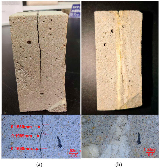
Figure 6.
Laboratory crack repair results: (a) pre-treatment crack morphology and (b) post-treatment morphology showing effective sealing.
3.3. Application of Repair Solution onto the Cracks Located in the Tunnel
Despite the fact that MICP and EICP offer good potential results in crack sealing and improving the durability of materials, most of the MICP and EICP studies published to date are focused on immersion or injection-based configurations in a laboratory frame [40]. However, aging infrastructure such as dam tunnels would need more practical approaches for implementation. In this research, MICP and EICP techniques were modified for on-site application using forced injection by a small electric pump, where the solution is directly introduced into the cracks, as shown in Figure 7.
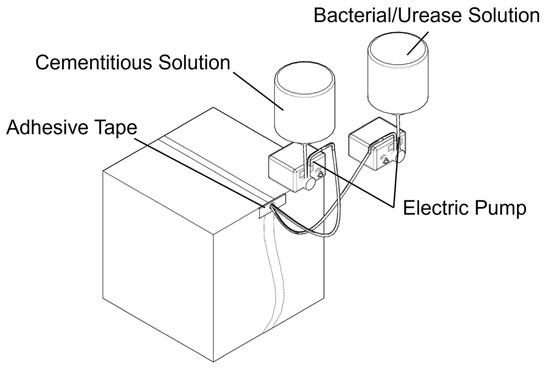
Figure 7.
Application of repair solution using electric pump.
Before any form of treatment, a strict cleaning process was performed in order to eliminate surface debris, loose particles, or contaminants that could spoil calcium carbonate precipitation. To optimize the flow and retention of the repair solution, a suitable application point was selected, typically at the highest accessible location along the crack line. At this point, a small hole was drilled to serve as an anchoring spot for the outlet of the pumping set. The pumping device’s arrangement was quite simple: two containers were suspended over the application area, one with the bacterial suspension or the cured urease enzyme and the other with the cementation solution. The solutions were made according to the description given in Section 3.1. To control solution spillage and direct the solution along the crack surface, the area surrounding the crack was physically fenced off with rudimentary barriers. This allowed the solution to be contained within the plane of the crack and seep slowly into the damaged area rather than gushing out. By means of pressured injection, solutions from each container were applied simultaneously to the fracture so that they could mix naturally within the crack cavity. The treatment was carried out twice a day over three consecutive days, with each session spaced 12 h apart. Every session was about five hours long and required a total of 1000 mL of solution for every cycle, composed of 500 mL of bacteria or urease solution and 500 mL of cementation solution. Electronic pumps, which allow exact volume, speed, and timing control, were used to guarantee consistent and precise delivery over the whole procedure. In this setup, 5 mL of each solution was dispensed every 3 min, which gave a 5 h treatment time for one session. This parameter setting is applicable to cracks with a width ranging from 0.1 mm to 0.3 mm and an approximate length of 40 cm. This stepwise approach tried to simulate the gradual mineralization processes obtained in controlled settings. Such in situ adaptations of MICP and EICP techniques extend the possibilities for restoring large inaccessible fractures in critical infrastructure. Figure 8 shows the general preparation of the treated cracks and application of the repair solutions.
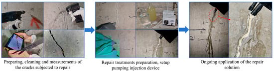
Figure 8.
Repair treatment procedure.
3.4. Evaluation of Bacteria and Cured Urease Activity
In this study, urease activity was evaluated by tracking changes in electrical conductivity over time using a method reported by Whiffin et al. [46]. For this purpose, a DDSJ-308F conductivity meter from Yidian Instrument Company (Foshan, China) was utilized. This approach is based on the principle that when urease catalyzes the breakdown of urea, it produces ammonium and carbonate ions, both of which carry an electric charge. While urea itself does not conduct electricity, the reaction products significantly increase the ionic strength of the solution, making it possible to follow the reaction’s progress through a conductivity meter. Two different urease sources were tested: a bacterial suspension intended for MICP and a urease extract obtained from cured soybeans, later applied in EICP. To ensure excess substrate relative to urease concentration and maintain enzymatic activity as the limiting factor, each of the urease solutions was combined with a 1.11 M urea solution in a 1:9 ratio (urease to urea). To maintain consistent conditions, measurements were taken at a stable temperature using a standard benchtop conductivity meter. Conductivity measurements were taken over a period of 15 min without interruption. As the ureolysis reaction continued, the rising conductivity provided an indirect measure of the enzyme’s catalytic performance. This approach enabled the rapid, non-intrusive measurement of reaction dynamics, providing valuable insight into practical scenarios involving crack repairs where urease-induced mineralization is crucial.
3.5. Acid-Washing Evaluation of Calcium Carbonate Content
An acid-washing method was used to quantify the calcium carbonate (CaCO3) precipitated in MICP and EICP methods [47]. This method relies on the reaction of calcium carbonate with acid, where it releases carbon dioxide, water, and a soluble calcium salt. In the present study, samples of calcium carbonate were dried to a constant weight at 60 °C. After the initial mass was measured, a known volume of dilute hydrochloric acid solution (HCl, usually 2 M) was added to each sample. The reaction of the acid with calcium carbonate is carried out as follows [48]:
CaCO3 (solid) + 2HCl (aqueous) → CaCl2 (aqueous) + CO2 (gas) + H2O (liquid)
This reaction will remove calcium carbonate but could leave behind some insoluble impurities. The solids remaining were filtered off and, while still wet, washed with deionized water before being dried to a constant weight. This approach allowed for the determination of how much CaCO3 actually got dissolved by the acid based on the difference in the dry mass. The loss of mass determined was indicative of the total CaCO3 content that was precipitated within the sample. This method provides a relatively simple and effective means to assess the efficiency of calcium carbonate precipitation in both MICP- and EICP-treated specimens.
3.6. Crystallography of Precipitated Calcium Carbonate—XRD
In order to identify the mineralogical aspects regarding the calcium carbonate produced from MICP and EICP treatments, X-ray Diffraction (XRD) analysis was performed. This method can be used to determine the crystalline phases of a given material based on how X-rays scatter when encountering the orderly placed atomic layers within the material. Each mineral has unique and specific diffracted patterns, which helps to identify the calcium carbonate phase as calcite, vaterite, or other polymorphs. During this study, calcium carbonate deposits were collected from cracks that were treated or repaired within the designated period. The treated samples were not disrupted during collection but were individually oven-dried and gently ground until a fine powder was obtained. Next, they were uniformly and thoroughly sieved to obtain particles with a 300-mesh size of about 50 μm. Such preparation was aimed at achieving uniform surfaces with regard to varying submicrometer defects that would interact and diffract with X-ray beams and thus decrease undesired background noise and increase peak clarity.
3.7. Morphology of Precipitated Calcium Carbonate—SEM
To observe the microstructural characteristics of calcium carbonate formed through MICP and EICP treatments, Scanning Electron Microscopy (SEM) was used. This technique provides highly detailed surface images by scanning the sample with a focused beam of electrons, revealing fine-scale features such as particle morphology, crystal size, texture, and porosity. In this research, small fragments were extracted from repaired crack surfaces where calcium carbonate had visibly accumulated. Each selected piece included both the deposited mineral layer and a thin section of the underlying cementitious substrate in order to not overly damage the precipitation products. The samples were gently rinsed with deionized water to remove surface dust and debris and then oven-dried overnight to prepare them for imaging.
4. Results and Discussion
4.1. Precipitation of Calcium Carbonate in Tunnel’s Crack
This section presents a visual evaluation of the crack sealing effectiveness achieved by MICP and EICP application based on selected crack examples from the dam’s tunnel [49,50]. Figure 9 and Figure 10 show the scope of surfaces changes before and after treatment, providing clear, visual confirmation of the effectiveness of each biomineralization method.
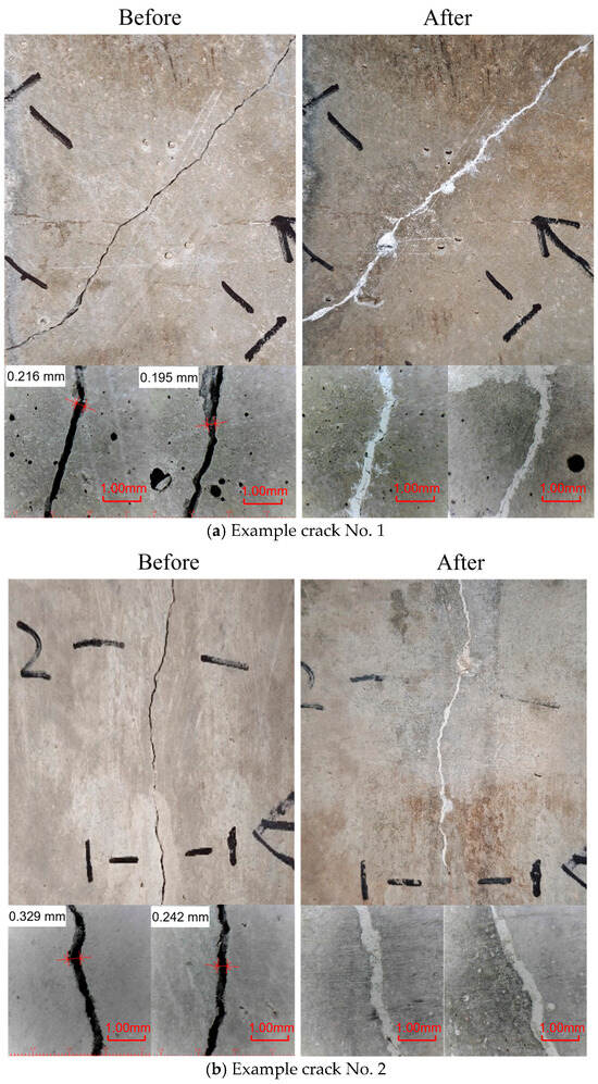
Figure 9.
Crack overview before and after MICP treatments.
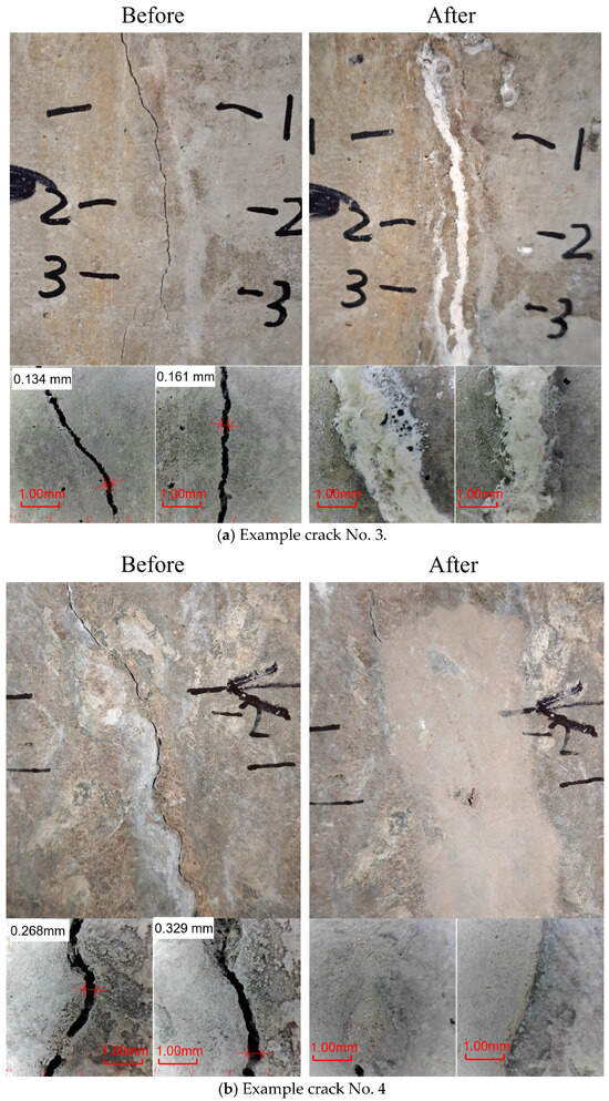
Figure 10.
Crack overview before and after EICP treatments.
Figure 9 highlights the sealing performance obtained via MICP. The images display two examples of cracks: one is relatively straight, while the other is more irregular and branching. These cracks are examples of possible paths for water penetration. Before treatment, the cracks appear as distinct voids with sharp edges and varying widths. After MICP is applied, the images reveal a significant transformation: the fissures are filled with a pale, mineralized substance that visibly reduces the crack aperture. Close-up images below each panel provide additional detail, showing that the deposited calcium carbonate adheres well to the internal surfaces of the cracks. The previously rough, porous surfaces now appear smoother, and the precipitate connects them, suggesting that the process of biomineralization occurred within the voids rather than merely coating the surface. This visual evidence suggests a sealing mechanism that combines mechanical filling and mineral interlocking at the crack interface.
Figure 10 shows the results of the EICP treatment. Figure 10a shows the untreated crack as a fine, linear fracture on the concrete surface. After treatment, the crack is fully sealed with a compact, whitish precipitate consistent with calcium carbonate formation. Close-up images reveal a dense, continuous fill that is well integrated with the original crack walls. Figure 10b features a wider, more irregular fracture and shows a similar trend. The EICP process produces a thicker mineral deposit that closely conforms to the crack’s morphology. It is noteworthy that the precipitate has propagated, forming a layer that connects the entire damaged area. A close-up view reveals that the crack is completely sealed. A visual examination of the treated cracks reveals the absence of any visible voids or discontinuities.
As demonstrated in Figure 9 and Figure 10, the visual observations confirm the efficacy of MICP and EICP treatments in sealing cracks of various complexities. The successful formation of calcium carbonate precipitations was observed in both cases, indicating the establishment of a well-bonded mineralized barrier [51,52]. The precipitated calcium carbonate is hypothesized to have restored surface continuity and thus reduced the permeability of the treated section. The MICP method seems to better fill narrower internal voids more integrally, while EICP can form broader, more uniform deposits even in wider or irregular cracks. These field observations provide a solid basis for further quantitative evaluations, such as permeability tests and mechanical bonding tests, to comprehensively characterize the long-term performance of these bio-based crack repair methods.
4.2. Bacteria and Enzyme Urease Activity
This section presents the results of the conductivity-based test used to monitor urease activity. The two curves captured in Figure 11 reflect different reaction profiles that are closely tied to the nature of the urease sources. In the case of the bacterial solution (Figure 11a), the conductivity curve is strikingly linear. This shows that the urea broke down evenly over the 15 min test. The steady slope (0.4572 mS/cm·min) indicates that the reaction happens at a predictable and controlled speed. This can be useful when the treatment process needs to be precisely adjusted or continued over a longer time, which is often the case in field-scale MICP applications. In contrast, the urease solution derived from cured soybeans (Figure 11b) exhibits a noticeably steeper and curved increase in conductivity. The reaction begins more aggressively, with a rapid release of ions, as evidenced by the higher initial slope (1.5883 mS/cm·min). However, the curve gently flattens out over time, suggesting a possible saturation effect or change in reaction dynamics. This behavior may be related to the nature of the purified enzyme extract. Although it provides high reactivity early on, the enzyme may require more careful handling to avoid uncontrolled precipitation during EICP applications.
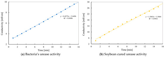
Figure 11.
Urease activity of bacteria and cured soybean enzyme.
The conductivity test not only validates urease function but also reveals how each system is likely to perform in practical applications. The bacterial solution offers stability and predictability, making it suitable for gradual mineralization strategies. Meanwhile, soybean-based urease provides intensity and speed, making it ideal for situations requiring a faster reaction time, although more precise dosing or timing may be necessary to avoid oversaturation.
4.3. Content of Calcium Carbonate in Precipitated Material
Figure 12 illustrates the effectiveness of calcium carbonate precipitation for both MICP and EICP as a percentage of the maximum theoretical value based on the reagent used. This assessment clarifies the degree to which each method utilizes the calcium and urea available to it in the form of a solid mineral for crystallization within identical treatment parameters. Analyzing the MICP results demonstrates that all three samples exhibited high precipitation efficiency, with values ranging from 91.1% to 95.5%. The average yield was approximately 93.75%, suggesting that the bacterial system utilized the provided reactants efficiently. This high performance is likely related to the bacteria’s dual role of providing the necessary urease for hydrolysis and acting as nucleation sites that promote more complete and uniform crystal formation. On the other hand, the EICP samples showed slightly lower values ranging between 81.5% and 86.1%, with an average of 84.17%. Although this is relatively efficient, it indicates that the enzyme-only system contains more unreacted material in the solution. This lower efficiency could be caused by several factors, such as an insufficient nucleation surface, uneven enzyme distribution, or rapid kinetics of the reaction, which could lead to incomplete mineral formation. This comparison shows that both systems effectively drive precipitation, but MICP slightly outperforms in converting available chemicals into solid calcium carbonate.
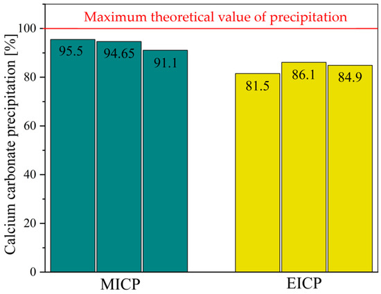
Figure 12.
Acid-washing evaluation of calcium carbonate content.
4.4. XRD–Outcome
The XRD results illustrate the differences in crystal structure and phase composition of calcium carbonate precipitated via MICP and EICP (Figure 13). In the case of MICP, the analysis reveals a mixture of two polymorphic forms, vaterite and calcite. The vaterite peaks are more numerous and intense, especially in the lower 2θ range (approximately 20–35°), indicating that vaterite is the dominant phase. Quantitative analysis confirms this, with the sample containing 58% vaterite and 42% calcite. This outcome is indicative of the microbial processes that have occurred, since the microorganisms are influenced by numerous factors such as the metabolic byproducts and local pH. The average size of crystallite calcium carbonate formed through MICP processes was 31.15 nm, showing the formation of moderately ordered nanocrystals. On the other hand, the XRD pattern for the sample obtained via EICP shows much more uniform mineralogy. For this sample, all peaks are predominantly calcite without vaterite peaks, which suggests better selection and stability in the crystallization pathway, probably because of the reaction environment resulting from using purified urease enzyme as opposed to living bacteria. The EICP process encourages direct precipitation of calcite, the thermodynamically most stable calcium carbonate [50]. In this case, the average crystallite size is slightly smaller at 30.22 nm, although this difference remains small. These results exhibit two distinctive differences between the methods.
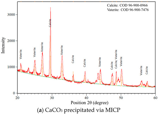
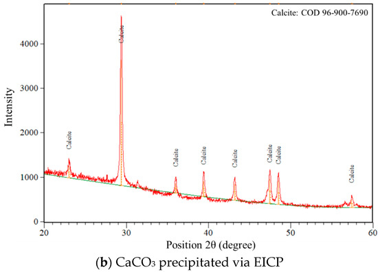
Figure 13.
XRD crystallography of precipitated calcium carbonate.
4.5. Morphology of CaCO3
Figure 14 presents SEM images that show the distinct morphological features of calcium carbonate precipitated via microbial (MICP) and enzyme-induced (EICP) approaches. Although both methods produce relatively dense accumulations of CaCO3, noticeable differences in microstructure are apparent. In the MICP sample (Figure 14a), the precipitates appear as irregular clusters of smooth, overlapping particles. The obtained morphology appears as a coarse, slightly chaotic surface formation, in which the crystals interconnect in a way that implies the simultaneous development of multiple nucleation and growth processes. Such morphology is likely influenced by the impact of microbial activity, namely the presence of microbial cells and byproducts of their metabolism, which may interfere with the uniform growth of the crystals. The layered appearance, which is a typical characteristic seen in many MICP processes, indicates the presence of biological interference during precipitation. In contrast, the EICP sample (Figure 14b) has a slightly different structure. The calcium carbonate particles are rougher and appear in a more spherical form, with better distribution and greater uniformity in size. These precipitations suggest a cleaner and more controlled environment for crystallization processes, likely because there are no living organisms in the EICP approach. The enzyme-catalyzed reaction seems to enhance orderliness in the process of crystallization as the crystals grow into dense clusters with clearly defined boundaries and few irregularities on their surfaces. While XRD confirms the dominant phase to be calcite, which typically comprises rhomboidal crystals, the spherical shapes observed in the SEM image are not conflicting. These structures are most likely due to the aggregation of nanocrystalline calcite into larger globular forms [53]. This is further supported by the rough surface texture seen in SEM under high magnitude. In addition, organic compounds like proteins were shown to stimulate high urease activity during the EICP process, which favors the growth of spherical-shaped crystals [54]. In addition, the initial stages of calcium carbonate formation in EICP may be amorphous or in the form of a nanocrystalline phase, which with time change to typical calcite shapes [55]. Overall, both methods precipitate substantial calcium carbonate deposition; MICP tends to yield more heterogeneous and biologically influenced formations, while EICP-precipitated structures are smoother, rounder, and more orderly, reflecting the cleaner, cell-free conditions under which the crystals are formed.
Figure 14.
Morphology of CaCO3 obtained via MICP and EICP.
4.6. Comparison with Other Repair Strategies
The repair method proposed in this study can be applied for on-site repair in real-world environments and thus possesses practical engineering application value. Currently, mainstream repair strategies rely on traditional methods, such as sealing cracks with epoxy resin [40]. However, these materials still face inherent limitations, including inadequate curing at low temperatures, limited weather resistance, and containing toxic solvents (e.g., xylene and paint thinners). In addition, some conventional crack repair methods adopt the grouting technique using cement–sodium silicate materials, in which a cement slurry is mixed with a sodium silicate solution and injected into the cracks. However, the strength of this material decreases sharply over time due to its poor resistance to underground water and the short gelation time often leads to premature reaction, causing blockage in the grouting pipes [56].
MICP and EICP exhibit significant potential for concrete crack repair; however, they confront substantial challenges regarding scalability and real-world operational effectiveness [57]. Most MICP- or EICP-related studies conducted to date are confined to controlled laboratory settings, which lack the ability to accurately replicate the conditions of real-world applications [58]. When conducting experimental crack repair using MICP and EICP in laboratory settings, the injection method and immersion method are typically employed. In bulk injection, a certain amount of solution is introduced within a very short time. The injected solution can be quickly absorbed by the cement-based material, which may significantly limit precipitation efficiency due to insufficient substrate availability. Instead, stepwise injection allows the solution to be supplied over a longer period to provide the necessary components for better precipitation. The repair strategy proposed in this study has been verified to be effective in real-world application scenarios. However, this method still has certain limitations, such as relatively high costs and lack of adaptability to harsh environments.
5. Conclusions
This study demonstrated that both MICP and EICP are effective and eco-friendly alternatives to conventional crack repair methods for dam service tunnels. Cracks of 0.1–0.3 mm were successfully sealed in field applications, confirming their technical feasibility and environmental benefits.
- 1.
- Both approaches are sustainable alternatives to conventional cementitious/epoxy repair, offering reduced environmental impact and technical feasibility in field applications. MICP offers long-term stability advantages, while EICP provides simpler preparation and faster precipitation.
- 2.
- MICP was more effective in sealing narrow cracks by utilizing microbial cells as localized nucleation sites, while EICP achieved more uniform filling of wider or irregular cracks owing to better dispersibility of the enzyme solution.
- 3.
- XRD and SEM analyses confirmed distinct mineralogical and morphological features. MICP produced mixed vaterite–calcite phases with irregular, biologically influenced clusters, whereas EICP yielded predominantly calcite with smoother and more uniform spherical deposits.
Future research should evaluate the long-term durability of CaCO3 precipitates under mechanical loading, hydraulic pressure, and environmental cycles, supported by field-scale monitoring to ensure reliable performance in service conditions.
Author Contributions
Conceptualization, X.Z.; Methodology, Y.Z. (Yu Zhang), H.L., J.Y. and M.J.J.; Investigation, J.Y.; Resources, X.Z., H.L., B.P. and Y.Z. (Yongzhi Zhang); Writing—original draft, X.Z., Y.Z. (Yu Zhang) and M.J.J.; Writing—review & editing, H.L., B.P., Y.Z. (Yongzhi Zhang), J.Y. and M.J.J.; Visualization, M.J.J.; Supervision, Y.Z. (Yu Zhang) and Y.Z. (Yongzhi Zhang); Project administration, X.Z., Y.Z. (Yu Zhang) and B.P. All authors have read and agreed to the published version of the manuscript.
Funding
This research was funded by the scientific research project support of China Three Gorges Corporation with grant number [Z532302055].
Data Availability Statement
Data are contained within the article.
Acknowledgments
Thanks for the scientific research project support of China Three Gorges Corporation (Contract number: Z532302055).
Conflicts of Interest
Authors Xu Zhang, Yu Zhang, Huiheng Luo, Bo Peng and Yongzhi Zhang were employed by the company China Three Gorges Corporation. The remaining authors declare that the research was conducted in the absence of any commercial or financial relationships that could be construed as a potential conflict of interest.
References
- Fan, Q.; Jiang, X.; Wang, K.; Huang, C.; Li, G.; Wei, P. Cement grouting online monitoring and intelligent control for dam foundations. J. Intell. Constr. 2023, 1, 1–15. [Google Scholar] [CrossRef]
- Wang, Z.; Mao, Y.; Tan, Y.; Shen, Q.; Xu, H. A safety evaluation method and system for a high core wall dam based on construction data. J. Intell. Constr. 2025, 3, 1–14. [Google Scholar] [CrossRef]
- Kim, M.O.; Bordelon, A.; Lee, M.K.; Oh, B.H. Cracking and failure of patch repairs in RC members subjected to bar corrosion. Constr. Build. Mater. 2016, 107, 255–263. [Google Scholar] [CrossRef]
- Kim, M.O.; Bordelon, A.C.; Lee, N.K. Early-age crack widths of thin fiber reinforced concrete overlays subjected to temperature gradients. Constr. Build. Mater. 2017, 148, 492–503. [Google Scholar] [CrossRef]
- Kim, M.O.; Bordelon, A. Determination of total fracture energy for fiber-reinforced concrete. Spec. Publ. 2015, 300, 1–16. [Google Scholar]
- Neville, A.M. Properties of Concrete, 5th ed.; Pearson Education Limited: Essex, UK, 2011. [Google Scholar]
- Pacheco-Torgal, F.; Jalali, S.; Fucic, A. Toxicity of Building Materials; Woodhead Publishing: Cambridge, UK, 2012. [Google Scholar]
- Mehta, P.K.; Monteiro, P.J.M. Concrete: Microstructure, Properties, and Materials, 4th ed.; McGraw-Hill Education: New York, NY, USA, 2014. [Google Scholar]
- Kayondo, M.; Combrinck, R.; Boshoff, W.P. State-of-the-art review on plastic cracking of concrete. Constr. Build. Mater. 2019, 225, 886–899. [Google Scholar] [CrossRef]
- Golewski, G.L. The Phenomenon of Cracking in Cement Concretes and Reinforced Concrete Structures: The Mechanism of Cracks Formation, Causes of Their Initiation, Types and Places of Occurrence, and Method of Detection—A Review. Buildings 2023, 13, 765. [Google Scholar] [CrossRef]
- Aldea, C.M.; Shah, S.P.; Karr, A. Effect of cracking on water and chloride permeability of concrete. Mater. Civ. Eng. 1999, 11, 181–187. [Google Scholar] [CrossRef]
- Thanoon, W.A.; Jaafar, M.S.; Razali, M.; Kadir, A.; Noorzaei, J. Repair and structural performance of initially cracked slabs. Constr. Build. Mater. 2005, 19, 595–603. [Google Scholar] [CrossRef]
- Francois, R.; Laurens, S.; Deby, F. Corrosion and Its Consequences for Reinforced Concrete Structures; ISTE Press: London, UK; Elsevier: Amsterdam, The Netherlands, 2018. [Google Scholar]
- Shaikh, F.U.A. Effect of cracking on corrosion of steel in concrete. Int. J. Concr. Struct. Mater. 2018, 12, 3. [Google Scholar] [CrossRef]
- Delatte, N. Failure, distress and repair of concrete structures. In Woodhead Publishing in Materials; Elsevier: Amsterdam, The Netherlands, 2009. [Google Scholar]
- Kim, T.K.; Park, J.S. Performance evaluation of concrete structures using crack repair methods. Sustainabillity 2021, 13, 3217. [Google Scholar] [CrossRef]
- Issa, C.A.; Debs, P. Experimental study of epoxy repairing of cracks in concrete. Constr. Build. Mater. 2007, 21, 157–163. [Google Scholar] [CrossRef]
- Safan, M.A.; Etman, Z.A.; Konswa, A. Evaluation of polyurethane resin injection for concrete leak repair. Case Stud. Constr. Mater. 2019, 11, e00307. [Google Scholar] [CrossRef]
- Somarathan, H.M.C.C.; Raman, S.N.; Mohotti, D.; Mutalib, A.A.; Badri, K.H. The use of polyurethane for structural and infrastructural engineering applications: A state-of-the-art review. Constr. Build. Mater. 2018, 190, 995–1014. [Google Scholar] [CrossRef]
- He, Z.J.; Zhu, X.D.; Wnag, J.J.; Mu, M.; Wang, Y. Comparison of CO2 emission from OPC and recycled cement production. Constr. Build. Mater. 2019, 211, 965–973. [Google Scholar] [CrossRef]
- Nie, S.; Zhou, J.; Yang, F.; Lan, M.Z.; Li, J.M.; Zhang, Z.Q.; Chen, Z.F.; Xu, M.F.; Li, H.; Sanjayan, J.G. Analysis of theoretical carbon dioxide emissions from cement production: Methodology and application. J. Clean. Prod. 2022, 334, 130270. [Google Scholar] [CrossRef]
- Seifan, M.; Berenjian, A. Microbially induced calcium carbonate precipitation: A widespread phenomenon in the biological world. Appl. Microbiol. Biotechnol. 2019, 103, 4693–4708. [Google Scholar] [CrossRef]
- Castro-Alonso, M.J.; Montanez-Hernandez, L.E.; Sanchez-Munoz, M.A.; Macias Franco, M.R.; Narayanasamy, R.; Balagurusamy, N. Microbially induced calcium carbonate precipitation (MICP) and its potential in bioconcrete: Microbiological and molecular concepts. Front. Mater. 2019, 6, 126. [Google Scholar] [CrossRef]
- Liu, D.; Shao, A.; Li, H.; Jin, C.; Li, Y. A study on the enhancement of the mechanical properties of weak structural planes based on microbiologically induced calcium carbonate precipitation. Bull. Eng. Geol. Environ. 2020, 79, 4349–4362. [Google Scholar] [CrossRef]
- Zhang, X.; Wang, H.; Wang, Y.; Wang, J.; Cao, J.; Zhang, G. Improved methods, properties, applications and prospects of microbial induced carbonate precipitation (MICP) treated soil: A review. Biogeotechnics 2025, 3, 100123. [Google Scholar] [CrossRef]
- Ahenkorah, I.; Rahman, M.; Karim, R.; Beecham SAnd Saint, C. A review of enzyme induced carbonate precipitation (EICP): The role of enzyme kinetics. Sustain. Chem. 2021, 2, 92–114. [Google Scholar] [CrossRef]
- Hu, W.; Cheng, W.C.; Wen, S.; Yuan, K. Revealing the enhancement and degradation mechanism affecting the performance of carbonate precipitation in EICP process. Front. Bioeng. Biotechnol. 2021, 9, 750258. [Google Scholar] [CrossRef]
- Choi, S.G.; Wang, K.; Wen, Z.; Chu, J. Mortar crack repair using microbial induced calcite precipitation method. Cem. Concr. Compos. 2017, 83, 209–221. [Google Scholar] [CrossRef]
- Sun, X.; Miao, L.; Wang, C. Glucose addition improves the bio-remediation efficiency for crack repair. Mater. Struct. 2019, 52, 111. [Google Scholar] [CrossRef]
- Jongvivatsakul, P.; Janprasit, K.; Nuaklong, P.; Pungrasmi, W.; Likitlersuang, S. Investigation of the crack healing performance in mortar using microbially induced calcium carbonate precipitation (MICP) method. Constr. Build. Mater. 2019, 212, 737–744. [Google Scholar] [CrossRef]
- Sun, X.; Miao, L. Application of Bio-remediation with bacillus megaterium for crack repair at low temperature. J. Adv. Concr. Technol. 2020, 18, 307–319. [Google Scholar] [CrossRef]
- Lu, C.; Li, Z.; Wang, J.; Zheng, Y.; Cheng, L. An approach of repair concrete vertical cracks using microbially induced carbonate precipitation driven by ion diffusion. J. Build. Eng. 2023, 73, 106798. [Google Scholar] [CrossRef]
- Dakhane, A.; Das, S.; Hansen, H.; O’Donnell, S.; Hanoon, F.; Rushton, A.; Perla, C.; Neithalath, N. Crack healing in cementitious mortars using enzyme-induced carbonate precipitation: Quantification based on fracture response. J. Mater. Civ. Eng. 2018, 30, 04018035. [Google Scholar] [CrossRef]
- Fan, Y.; Du, H.; Wei, H. Characteristics of soybean urease mineralized calcium carbonate and repair of concrete surface damage. J. Wuhan Univ. Technol. Mater. Sci. 2021, 36, 70–76. [Google Scholar] [CrossRef]
- Wei, H.; Fan, Y.; Sun, L.; Du, H.; Liang, R. Experimental study on high-temperature damage repair of concrete by soybean urease induced carbonate precipitation. Materials 2022, 15, 2436. [Google Scholar] [CrossRef]
- Yuan, H.; Ru, M.; Dong, W.; Zhu, X.; Zhao, Z. Crack repair in in-service tunnel linings using chitosan-combined enzyme-induced carbonate precipitation. J. Mater. Civ. Eng. 2024, 36, 04024365. [Google Scholar] [CrossRef]
- Li, G.; Yan, D.; Liu, J.; Yang, P.; Zhang, P. Experimental study on the crack concrete repaired via enzyme-induced calcium carbonate precipitation (EICP). Materials 2024, 17, 3205. [Google Scholar] [CrossRef]
- Wang, Y.; Chen, Y.; Marchelina, N. Crack repairing performance by soybean urease induced calcium carbonate precipitation (SICP) combined with fibers and lightweight aggregates. Constr. Build. Mater. 2025, 458, 139678. [Google Scholar] [CrossRef]
- Jiang, L.; Xia, H.; Hu, S.; Zhao, X.; Wang, W.; Zhang, Y.; Li, Z. Crack-healing ability of concrete enhanced by aerobic-anaerobic bacteria and fibers. Cem. Concr. Res. 2024, 183, 107585. [Google Scholar] [CrossRef]
- Zhang, Y.S.; Liu, Y.; Sun, X.D.; Zeng, W.; Xing, H.; Lin, J.; Kang, S.; Yu, L. Application of microbially induced calcium carbonate precipitation (MICP) technique in concrete crack repair: A review. Constr. Build. Mater. 2024, 411, 134313. [Google Scholar] [CrossRef]
- Ghosh, T.; Bhaduri, S.; Montemagno, C.; Kumar, A.; Achal, V. Sporosarcina pasteurii can form nanoscale calcium carbonate crystals on cell surface. PLoS ONE 2019, 14, e0210339. [Google Scholar] [CrossRef]
- Ngoma, M.C.; Kolawole, O. Porosity and bedding controls on bio-induced carbonate precipitation and mechanical properties of shale and dolomitic rocks: EICP vs MICP. Biogeotechnics 2024, 2, 100102. [Google Scholar] [CrossRef]
- Gao, Y.; He, J.; Tang, X.; Chu, J. Calcium carbonate precipitation catalyzed by soybean urease as an improvement method for fine-grained soil. Soils Found. 2019, 59, 1631–1637. [Google Scholar] [CrossRef]
- Liu, M.; Chen, X.; Cai, L.; Luo, H. Regulatory mechanism of humic substances on microbially induced carbonate precipitation. Constr. Build. Mater. 2025, 458, 139581. [Google Scholar] [CrossRef]
- Intarasoontron, J.; Pungrasmi, W.; Nuaklong, P.; Jongvivatsakul, P.; Likitlersuang, S. Comparing performances of MICP bacterial vegetative cell and microencapsulated bacterial spore methods on concrete crack healing. Constr. Build. Mater. 2021, 302, 124227. [Google Scholar] [CrossRef]
- Whiffin, V.S.; van Paassen, L.A.; Harkes, M.P. Microbial carbonate precipitation as a soil improvement technique. Geomicrobiol. J. 2007, 24, 417–423. [Google Scholar] [CrossRef]
- Zhan, Q.; Qian, C. Stabilization of sand particles by bio-cement based on CO2 capture and utilization: Process, mechanical properties and microstructure. Constr. Build. Mater. 2017, 133, 73–80. [Google Scholar] [CrossRef]
- Park, S.; Ahn, Y.; Lee, S.; Choia, J. Calcium carbonate synthesis from waste concrete for carbon dioxide capture: From laboratory to pilot scale. J. Hazard. Mater. 2021, 403, 123862. [Google Scholar] [CrossRef]
- Zhang, G.Z.; Liu, C.; Zhang, J.; Wang, H.; Liu, J. Enhanced MICP efficacy for cracks repair of marine mortar with coral sand: Coupled effects of seawater and basalt fiber on products morphology. Constr. Build. Mater. 2025, 470, 140647. [Google Scholar] [CrossRef]
- Huang, W.; Fan, L.; Peng, S.; Qi, Y.; Chen, G.; Liu, X. Experimental study on the principal factors influencing the effectiveness of microbial-induced calcium carbonate precipitation in asphalt concrete crack repair based on response surface methodology. Road Mater. Pavement Des. 2025, 1–23. [Google Scholar] [CrossRef]
- Lee, H.W.; Rahmaninezhad, S.A.; Meng, L.; Srubar, W.V.; Sales, C.M.; Farnam, Y.; Hubler, M.H.; Najafi, A.R. Prediction of microbial-induced calcium carbonate precipitation for self-healing cementitious material. Cem. Concr. Compos. 2025, 158, 105945. [Google Scholar] [CrossRef]
- Lin, R.S.; Liao, Y.; Fu, C.; Pan, T.-H.; Guo, R.; Wang, X.-Y. Mechanism analysis of microwave-carbonation solidification for carbide slag-based low-carbon materials. Cem. Concr. Compos. 2025, 157, 105938. [Google Scholar] [CrossRef]
- Sondi, I.; Skapin, S.D.; Salopek-Sondi, B. Biomimetic precipitation of nanostructured colloidal calcite particles by enzyme-catalyzed reaction in the presence of magnesium ions. Cryst. Growth Des. 2008, 8, 435–441. [Google Scholar] [CrossRef]
- Aishwarya, T.; Ashish, J. Impact of solution chemistry on morphology of enzyme induced calcium carbonate precipitation. Emerg. Mater. Res. 2023, 12, 346–357. [Google Scholar] [CrossRef]
- Cao, G.; Liu, S.; Yu, J.; Cai, Y.; Hu, Z.; Mao, K. Enzyme-induced calcium carbonate precipitation (EICP) and its application in geotechnical engineering. Geol. J. China Univ. 2021, 27, 754–768. (In Chinese) [Google Scholar]
- Zhang, B. Modified Cement-Sodium Silicate Material and Grouting Technology for Repairing Underground Concrete Structure Cracks. Arab. J. Geosci. 2019, 12, 680. [Google Scholar] [CrossRef]
- Omoregie, A.I.; Wong, C.S.; Rajasekar, A.; Ling, J.H.; Laiche, A.B.; Basri, H.F.; Sivakumar, G.; Ouahbi, T. Bio-based solutions for concrete infrastructure: A review of microbial-induced carbonate precipitation in crack healing. Buildings 2025, 15, 1052. [Google Scholar] [CrossRef]
- Fan, Q.; Fan, L.; Quach, W.M.; Duan, J. The impact of seawater ions on urea decomposition and calcium carbonate precipitation in the MICP process. Cem. Concr. Compos. 2024, 152, 105631. [Google Scholar] [CrossRef]
Disclaimer/Publisher’s Note: The statements, opinions and data contained in all publications are solely those of the individual author(s) and contributor(s) and not of MDPI and/or the editor(s). MDPI and/or the editor(s) disclaim responsibility for any injury to people or property resulting from any ideas, methods, instructions or products referred to in the content. |
© 2025 by the authors. Licensee MDPI, Basel, Switzerland. This article is an open access article distributed under the terms and conditions of the Creative Commons Attribution (CC BY) license (https://creativecommons.org/licenses/by/4.0/).