Article

Semi-Analytical Method for the Response of Existing Tunnels to Tunneling Considering the Tunnel–Soil Interaction Based on the Modified Gaussian Function

by
Hualin Zhang
1,
Ahmed Altaib Hussain Suliman Hussaina
1,
Lv Liu
2,
Chaoqun Huang
2,
Dong Huang
2,
Rongzhu Liang
1 and
Wenbing Wu
1,*
1
Faculty of Engineering, China University of Geosciences, Wuhan 430074, China
2
Wuhan Municipal Construction Group Co., Ltd., Wuhan 430023, China
*
Author to whom correspondence should be addressed.
Buildings 2025, 15(16), 2849; https://doi.org/10.3390/buildings15162849
Submission received: 3 July 2025 / Revised: 6 August 2025 / Accepted: 10 August 2025 / Published: 12 August 2025
(This article belongs to the Special Issue Soil–Structure Interactions for Civil Infrastructure)

Abstract

The behavior response of an existing shield tunnel to under-cross tunneling is fundamentally governed by the tunnel–soil interaction. In this study, the existing tunnel is simplified as a single-variable Timoshenko beam to address the shear locking issue of the conventional Timoshenko beam. An elastic continuum solution, which can be degenerated into the Winkler–Timoshenko model, is established by considering the tunnel–soil interaction to evaluate the existing tunnel’s response to underlying tunneling. Meanwhile, greenfield settlement is described using a modified Gaussian function to fit practical engineering cases. The joint opening and segmental dislocation are also quantified. The applicability of the proposed method is validated by two reported engineering cases, where measured greenfield settlements are used to verify the modified Peck formula. Key parameters, including the ground loss rate, intersection angle, tunnel–soil stiffness factor, and vertical clearance, are discussed. The results show that the proposed method can provide references for predicting the potential diseases of existing tunnels affected by new tunnel excavation.

1. Introduction

As an effective solution to alleviate urban traffic congestion, subway tunnel networks have been established in worldwide cities. However, the compression of a shallow underground space poses new challenges for new tunnel construction. With the increasing density of subway shield tunnels, more and more new shield tunnels are inevitably constructed by under-crossing existing ones. Shield technologies (e.g., earth pressure balance shields and slurry shields) are widely used in clayey soils, but tunneling inevitably disturbs the surrounding soils, as documented by numerous studies [1,2,3,4,5,6,7,8]. Cumulative soil disturbance can cause excessive displacements in overlying existing tunnels, threatening their structural stability and serviceability [9,10]. Thus, investigating the impact of under-cross tunneling on existing subway lines is crucial for predicting deformation and ensuring tunnel safety, stability, and durability.
The influence of new tunnel excavation on existing tunnels is primarily longitudinal, with negligible circumferential effects [11,12,13,14,15,16,17]. Longitudinal deformations of existing tunnels include settlement, joint opening, and segmental dislocation. Settlement affects vehicle operation safety and comfort, while joint opening and segmental dislocation relate to structural stability [18,19]. Numerical simulation, model testing, analytical methods, and empirical formulae are predominantly used to assess the existing tunnel response to tunneling underneath. Nowadays, numerous cases have adopted numerical simulations to predict existing deformation behavior, which can account for the properties of field soils and yield good agreement with the measured data [20,21,22,23]. However, numerical simulations depend on typical soil constitutive models, which cannot fully represent the soil’s properties. In addition, the selection of constitutive parameters relies on the preliminary simulation and laboratory or field tests. Moreover, model tests, including reduced-scale model tests and centrifuge model tests, are conducted to investigate the mechanism through which tunneling impacts the existing tunnel, which have provided some references for investigating existing tunnel settlement and the distribution of internal forces induced by tunneling underneath [9,24,25,26,27]. Nevertheless, this method lacks insight into the interaction mechanism between new and existing tunnels, and the costs are usually high.
At present, numerous analytical approaches have been developed to predict the response of existing tunnels induced by adjacent new tunnel excavation. These methods offer valuable insights and design guidance during the preliminary stage while avoiding high computational costs. To characterize tunnel deformation behavior, several Winkler-type models, where the soil reaction is modeled by a series of independent elastic springs, have been proposed and are validated to be of significance in simulating the tunnel–soil interaction [28,29,30,31]. However, research by Klar et al. [32] highlights that elastic continuum solutions are generally more reliable than Winkler-based solutions when predicting pipeline responses to tunneling. The elastic continuum framework proposed by Klar et al. [32,33] treats the existing tunnel as an Euler–Bernoulli beam and the foundation soil as an elastic continuum. Similar to the two-stage methodology [28,31,34,35], this approach first calculates the greenfield settlement along the existing tunnel axis and then solves the tunnel–soil interaction using analytical techniques. Compared to Winkler-type models, the elastic continuum solution excels in rigorously simulating the soil continuum involved in the soil–structure interaction. Recent studies by Franza and Viggiani [36], using a standard Gaussian curve, have shown that the shear factor significantly influences both shear and bending deformations in affected tunnels. However, joint deformations, including opening and dislocation, warrant further investigation to refine predictive models.
Furthermore, both ground and subsurface settlement due to shield tunneling have been explored by many scholars [1,2]. The empirical function proposed by Peck, commonly referred to as the Peck formula, has gained widespread adoption for predicting stratum displacement and underground structure settlement due to its computational simplicity. This formula features two critical parameters: the maximum settlement Smax(z) and the settlement trough width i(z), which together define the shape of the settlement curve at varying depths of the stratum. Building upon the standard Gaussian curve, numerous studies have leveraged existing empirical frameworks to model tunnel-induced ground and subsurface settlements [2,37,38,39,40,41]. These empirical formulae have also proven effective in describing greenfield settlements, serving as a basis for predicting settlements in existing structures affected by new tunnel excavations [3,10,42,43]. However, the Gaussian function lacks a rigorous theoretical foundation, necessitating its application primarily through back-analysis methods to derive specific expressions [21,42,44,45].
To address the limitations of the prior studies outlined above, this research endeavors to develop a semi-analytical method that employs a single-variable Timoshenko beam model. This approach is designed to characterize joint deformations while mitigating the shear locking issues inherent in conventional Timoshenko beam formulations. The greenfield settlement is described using a Gaussian function, theoretically derived and calibrated with extensive field observation data to enhance its applicability in real-world engineering scenarios. Furthermore, a Timoshenko-elastic continuum solution is established to account for existing tunnel–soil interactions. This solution is compared with the Winkler–Timoshenko solution under varying subgrade modulus conditions. The proposed modified Gaussian function and semi-analytical method are validated through two engineering case studies, which include measurements of both greenfield settlement and tunnel displacement. Key parameters, including the ground loss rate, intersection angle, tunnel-soil stiffness factor, and vertical clearance, are systematically analyzed to elucidate their influence on the deformation behavior of existing tunnels.

2. The Elastic Continuum Solution of Existing Tunnel Deformation

2.1. Single-Variable Formulation of a Timoshenko Beam

The Timoshenko beam theory is widely adopted to model the deformation of existing tunnels as it accounts for both bending and shear deformations. The conventional two-variable differential equations for a Timoshenko beam can be expressed as:
E I d 2 θ d x 2 + κ G A ( d w d x θ ) = 0 κ G A ( d 2 w d x 2 d θ d x ) = p
where E is the Young’s modulus of the segment lining, I is the cross-sectional moment of inertia, θ is the cross-sectional rotation angle, κ is the shear correction coefficient (0.5 for annular cross-sections), G is the shear modulus, A is the cross-section area, w is the neutral axis deflection of the beam, p is the applied transverse load, EI is the bending stiffness, and κGA is the shear stiffness.
Completing the solution for Timoshenko beam deformations typically requires resolving the shear locking issue, which necessitates decoupling Equation (1). Fortunately, Kindl et al. [46] proposed a bending-displacement-based single-variable governing differential equation, through which all variables of the Timoshenko beam can be expressed in terms of this displacement variable and its derivatives. Compared with a conventional Timoshenko beam, the single-variable Timoshenko beam solves the shear locking problem that exists in the former. In addition, the single-variable Timoshenko beam has the advantages of being simple to calculate and having the capability to model tunnel deformations under the influence of additional loads [47,48].
The expressions for all Timoshenko beam variables are as follows:
w = w b + w s , w = w b E I κ G A d 2 w b d x 2 , w s = E I κ G A d 2 w b d x 2
θ = d w b d x , γ = E I κ G A d 3 w b d x 3
M = E I d 2 w b d x 2 , Q = E I d 3 w b d x 3 , E I d 4 w b d x 4 = p
where wb is the bending displacement, ws is the shear displacement, and γ is the shear angle.
The governing equation (Equation (2)) proposed by Kindl et al. [46] effectively overcomes the shear locking issue inherent in the conventional Timoshenko beam theory while offering the distinct advantage of computational simplicity.

2.2. Elastic Continuum Solution of Existing Tunnel Deformation

Klar et al. [32] introduced an elastic continuum method to forecast pipeline deformations induced by new shield tunnel excavation, yielding favorable results. Building upon their research, this study adheres to the same foundational assumptions: (1) the existing tunnel maintains continuous contact with the foundation soil throughout the deformation process; (2) the new tunneling operation remains unaffected by the presence of the existing tunnel; (3) the soil response to additional loading is independent of the existing tunnel; and (4) greenfield settlement along the existing tunnel axis conforms to the Gaussian curve model.
As illustrated in Figure 1, the existing tunnel is modeled using a single-variable Timoshenko beam, and an elastic continuum solution is employed to simulate the tunnel–soil interaction. The existing tunnel, with a total length of L, is discretized into n + 5 nodes (including two virtual nodes at each end of the existing tunnel), with a distance of l between adjacent nodes. Owing to the greenfield settlement, the interaction between the tunnel and the foundation soil will result in the deformation of the existing tunnel.
Given that w is a single-variable function of wb in Equation (2a) (w = f (wb)), the deformation of the existing tunnel can be solved by only calculating the bending deformation. By employing the finite difference method (FDM), Equation (2a) can be rewritten as:
w i = w b ( i ) E I κ G A w b ( i 1 ) 2 w b ( i ) + w b ( i + 1 ) l 2
where wi denotes the deflection of the existing tunnel at node i, wb(i) denotes the bending deformation at node i, and l is the spacing between two adjacent nodes (L = nl, with L being the total calculated length of the existing tunnel).
Furthermore, the bending moment M and shear force Q in Equation (2c) can be discretized using the following equations:
M i = E I w b ( i + 1 ) 2 w b ( i ) + w b ( i 1 ) l 2
Q i = E I w b ( i + 2 ) 2 w b ( i + 1 ) + 2 w b ( i 1 ) w b ( i 2 ) 2 l 3
where Mi and Qi denote the bending moment and shear force at node i, respectively.
Assuming both ends of the existing tunnel satisfy free boundary condition, the bending moments and shear forces at both ends of the existing tunnel are equal to zero (M0 = Mn = 0, Q0 = Qn = 0). This allows the virtual nodes to be derived, with their expressions given by:
w b ( 2 ) = 4 w b ( 0 ) 4 w b ( 1 ) + w b ( 2 ) w b ( 1 ) = 2 w b ( 0 ) w b ( 1 ) w b ( n + 1 ) = 2 w b ( n ) w b ( n 1 ) w b ( n + 2 ) = 4 w b ( n ) 4 w b ( n 1 ) + w b ( n 2 )
Substituting Equation (5) into Equation (3) allows the latter to be reformulated in matrix form, as expressed below:
w = ( E + S T ) w b
where w is the deformation matrix of the existing tunnel, E is the identity matrix, wb is the bending deformation matrix, and ST is the finite difference coefficient matrix, whose expression is given by:
S T = E I κ G A l 2 0 0 1 2 1 1 2 1 0 0 ( n + 1 ) × ( n + 1 )
Similarly, the bending moment and shear force can also be derived as:
M = S M w b
Q = S Q w b
where SM and SQ denote the bending moment matrix and shear force stiffness matrix, with their expressions given by:
S M = E I l 2 0 1 2 1 1 2 1 0 ( n + 1 ) × ( n + 1 )
S Q = E I 2 l 3 0 0 1 2 1 1 2 0 2 1 1 2 0 2 1 1 2 1 0 0 ( n + 1 ) × ( n + 1 )
The bending deformation wb can be solved from Equation (2c) through the following equation:
E I w b ( i 2 ) 4 w b ( i 1 ) + 6 w b ( i ) 4 w b ( i + 1 ) + w b ( i + 2 ) l 4 = p i
where pi denotes the additional load at node i.
Substituting the boundary condition equation (Equation (5)) into Equation (10), the bending deformation of the existing tunnel can be expressed as:
S w b = p
where wb denotes the bending deformation matrix, p represents the applied load matrix resulting from the interaction between the existing tunnel and the foundation soil, and S denotes the bending stiffness of the existing shield tunnel, expressed as:
S = E I l 4 2 4 2 0 2 5 4 1 1 4 6 4 1 1 4 6 4 1 1 4 5 2 2 4 2 ( n + 1 ) × ( n + 1 )
To satisfy Assumption (1), the displacement w in Equation (6) can be divided into three components: local displacement, additional displacement, and greenfield settlement, expressed as:
w = w C L + w C A P + w C A T
where wCL is defined as the local displacement, representing the displacement at a point induced exclusively by its own loading; wCAP denotes the additional displacement arising from forces generated by the soil–tunnel interaction; and wCAT signifies the greenfield settlement.
Combining Equations (6) and (13) gives:
w C L + w C A P + w C A T = ( E + S T ) w b
The local displacement wCL and additional displacement wCAP can be calculated using the following expressions:
w CL i = q i G i i
w CAP = j = 1 j i n q j G i j
where qi and qj represent the forces acting on the soil medium at nodes i and j, respectively, arising from the tunnel–soil interaction. Gii and Gij denote Green’s function, which defines the elastic soil continuum displacement at point i due to unit loads applied at points i and j, respectively.
Based on the Mindlin solution [49], Gij in Equation (15) is expressed as:
G i j = 1 16 π E s ( 1 υ s ) ( 3 4 υ s R 1 G + ( z i z j ) 2 R 1 G 3 + 8 ( 1 υ s ) 2 ( 3 4 υ s ) R 2 G + ( 3 4 υ s ) ( z i + z j ) 2 2 z i z j R 2 G 3 + 6 z i z j ( z i + z j ) 2 R 2 G 5 )
where Es and υs represent the elastic modulus and Poisson’s ratio of the foundation soil, respectively. R1G and R2G are given by the following expressions:
R 1 G = ( x i x j ) 2 + ( y i y j ) 2 + ( z i z j ) 2
R 2 G = ( x i x j ) 2 + ( y i y j ) 2 + ( z i + z j ) 2
where (xiyizi) and (xjyjzj) are the coordinates of the point where the unit load is applied and the calculation point, respectively.
However, it is important to note two critical issues that must be addressed before applying the Mindlin solution. First, the Mindlin solution is predicated on the assumption that soil behaves as an elastic semi-infinite body; second, the displacement at the loading point cannot be directly calculated using the Mindlin solution.
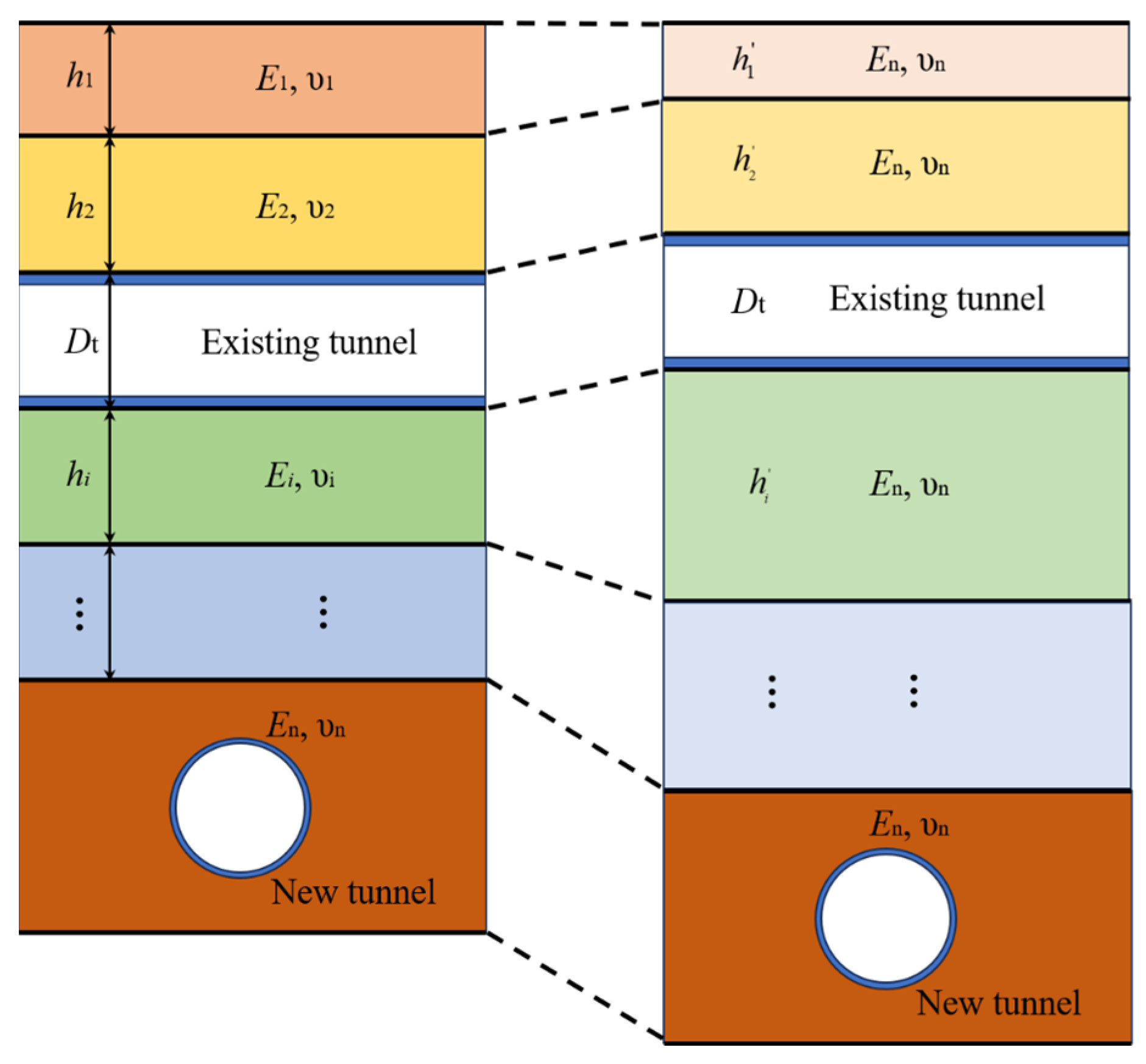
To address the first issue, the soil can be homogenized using the equivalent layer method proposed by Paklovsky, as illustrated in Figure 2, which is based on wave propagation theory. Wang [50] further derived formulae suitable for three-layer materials. Ultimately, the equivalent layer method for multilayer materials can be derived based on wave propagation theory, with its expression given by:
h = h i ρ n E i E n ρ i
where hi is the thickness of the i-th soil layer; ρn and ρi denote the densities of the n-th and i-th soil layers, respectively; and En and Ei represent the elastic moduli of the n-th and i-th soil layers, respectively.
To address the second issue, a reference displacement at the loading point is calculated by transforming the unit load at a different node j into a uniformly distributed load with intensity q = 1/Dtl, where Dt denotes the outer diameter of the existing tunnel [51]. As illustrated in Figure 3, to calculate the displacement at node i induced by the uniform load on the j-th section, a random area (dA = dadb) is selected. The load on this area can be obtained (dq = dadb/Dtl). Consequently, Gij can be obtained by integrating Equation (16):
G i j = l / 2 l / 2 D t / 2 D t / 2 d a d b 16 π E s ( 1 υ s ) D t l ( 3 4 υ s R 1 G + 8 ( 1 υ s ) 2 ( 3 4 υ s ) R 2 G + 2 ( 5 8 υ s ) z i 2 R 2 G 3 + 24 z i 4 R 2 G 5 )
Similarly, Gii can also be derived using the aforementioned method, with its expression given by:
G i i = l / 2 l / 2 D t / 2 D t / 2 d a d b 16 π E s ( 1 υ s ) D t l ( 3 4 υ s R 1 G + 8 ( 1 υ s ) 2 ( 3 4 υ s ) R 2 G + 2 ( 5 8 υ s ) z i 2 R 2 G 3 + 24 z i 4 R 2 G 5 )
Based on the principle of action–reaction forces, Equation (15a) can be rewritten as:
p i = q i = w CL i G i i
Combining Equations (11), (14), and (21), the following relation can be obtained:
S w b + K * S T w b + K * w b = K * w C A P + K * w C A T
where K* can be expressed as follows:
K * = 1 G i i , i = j 0 , i j
Combining Equations (11) and (15b), the additional displacement wCAP can be expressed as:
w C A P = λ s * S w b
where λ S * is given by:
λ s * = G i j , i j 0 , i = j
Substituting Equation (24) into Equation (22) yields:
( S + K * S T + K * + K * λ s * S ) w b = K * w C A T
Then, the single-variable Timoshenko beam elastic continuum-based solution can be derived by numerically solving Equation (26) once the wCAT is determined.

2.3. Greenfield Settlement at the Existing Tunnel Axis

Peck proposed using a Gaussian curve to describe the ground settlement profile induced by tunneling based on extensive field observations, and the expression is given as:
S ( x ) = S max exp ( x 2 2 i 2 )
where Smax is the maximum settlement at the ground surface; i denotes the distance from the vertical centerline to the inflection point of the Gaussian curve at the ground surface, commonly referred to as the settlement trough width; and x represents the horizontal distance from the vertical tunnel centerline.
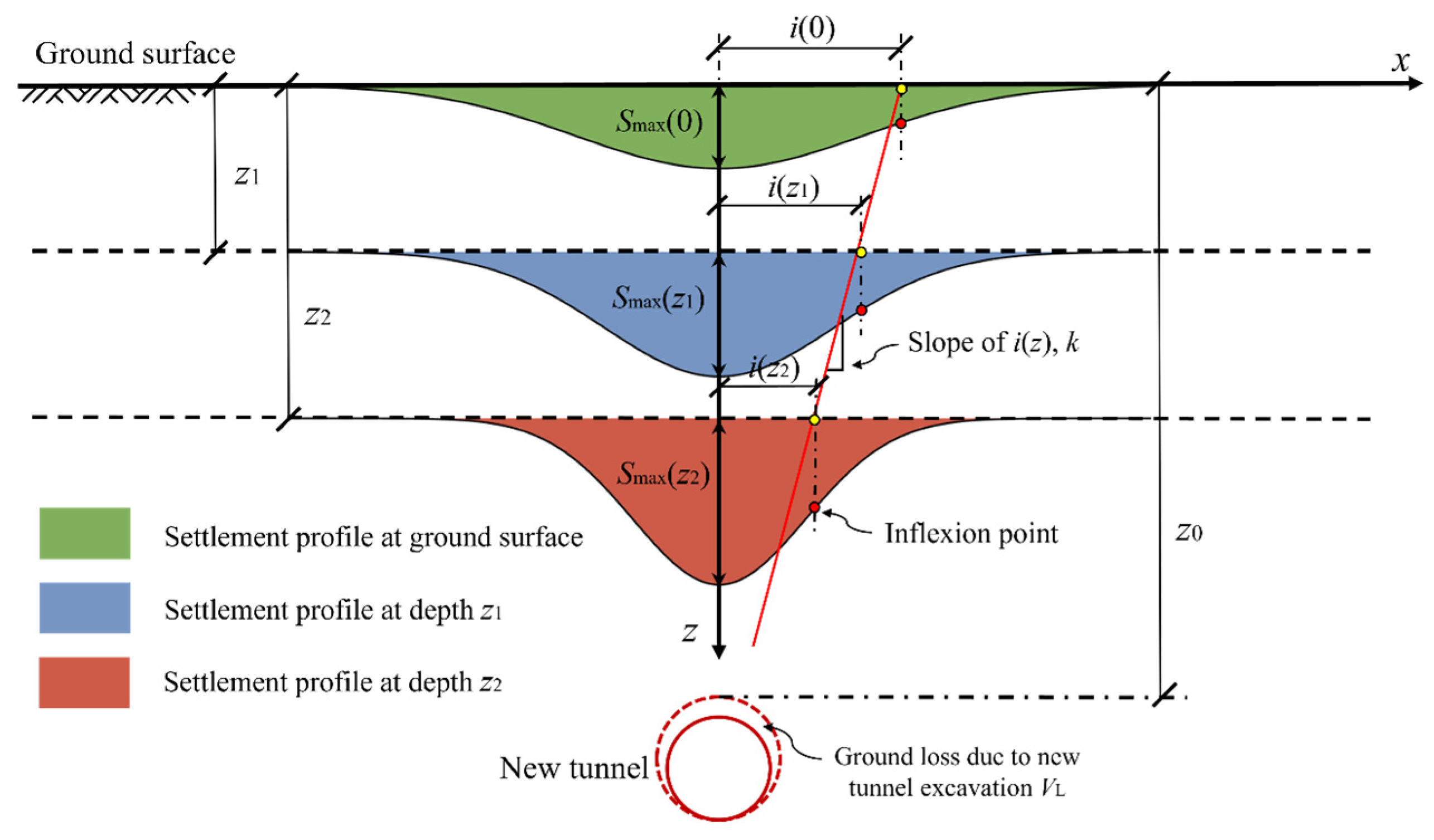
As shown in Figure 4, O’reilly and New [52] demonstrated that the subsurface settlement at a fixed depth can also be characterized by a Gaussian distribution based on comprehensive field measurements. Consequently, Equation (27) can be rewritten as:
S ( x , z ) = S max ( z ) exp ( x 2 2 i ( z ) 2 )
where Smax(z) denotes the maximum settlement at depth z, and i(z) represents the settlement trough width at depth z.
It is evident that the two variables Smax(z) and i(z) in Equation (28) must be determined prior to calculating the greenfield settlement at an arbitrary point (x, z). Findings from field engineering and model tests show that Smax(z) increases nonlinearly from the ground surface to the tunnel crown [41]. Accordingly, a power function proposed by Lu et al. [40] is introduced to characterize the subsurface settlement:
S max ( z ) = S max ( 0 ) S max ( z 0 ) ( 1 z z 0 ) 1 n + S max ( z 0 )
where z0 is the buried depth of the new tunnel crown; Smax(0) and Smax(z0) denote the maximum settlements at the ground surface and new tunnel crown, respectively. n is a parameter that determines the change rate of Smax(z) with depth and comprehensively reflects the influence of various factors on Smax(z). In strata predominantly composed of clay layers, n exhibits a nonlinear relationship with α (α = Smax(0)/Smax(z0)) according to Lu et al.’s [40] research, and Equation (29) can be expressed as:
S max ( z ) = S max ( z 0 ) ( α 1 ) ( 1 z z 0 ) α 0.97 + 1
Substituting Equation (30) into Equation (28), the settlement at an arbitrary point (x, z) can be given as:
S ( x , z ) = S max ( z 0 ) ( α 1 ) ( 1 z z 0 ) α 0.97 + 1 exp ( x 2 2 i ( z ) 2 )
However, S(x, z) is the function of six parameters: the maximum settlement at the ground surface and new tunnel crown, the buried depth of the new tunnel crown, the settlement trough width, and the horizontal and vertical coordinates of point (x, z) (i.e., S(x, z) = f (Smax(0), Smax(z0), i(z), z0, x and z)). Lin et al. [41] proposed a novel analytical method to predict subsurface settlements at any arbitrary depth, which requires the initial determination of Smax(0), Smax(z0), and i(z) based on measured settlement data. Notably, in actual engineering practice, there are often no measured data available to predict the greenfield settlement at the axis of an existing tunnel before new tunnel excavation. Therefore, this paper proposes an improved analytical method for predicting greenfield settlements that is built upon Equation (31).
Mair et al. [37] proposed Equation (32) based on the Peck formula. By integrating field-measured data from new tunnel excavations and results from centrifuge model tests, they developed this equation to predict the maximum ground surface settlement induced by tunneling in clayey soil layers:
S max ( 0 ) = 0.313 V L D 2 i ( 0 )
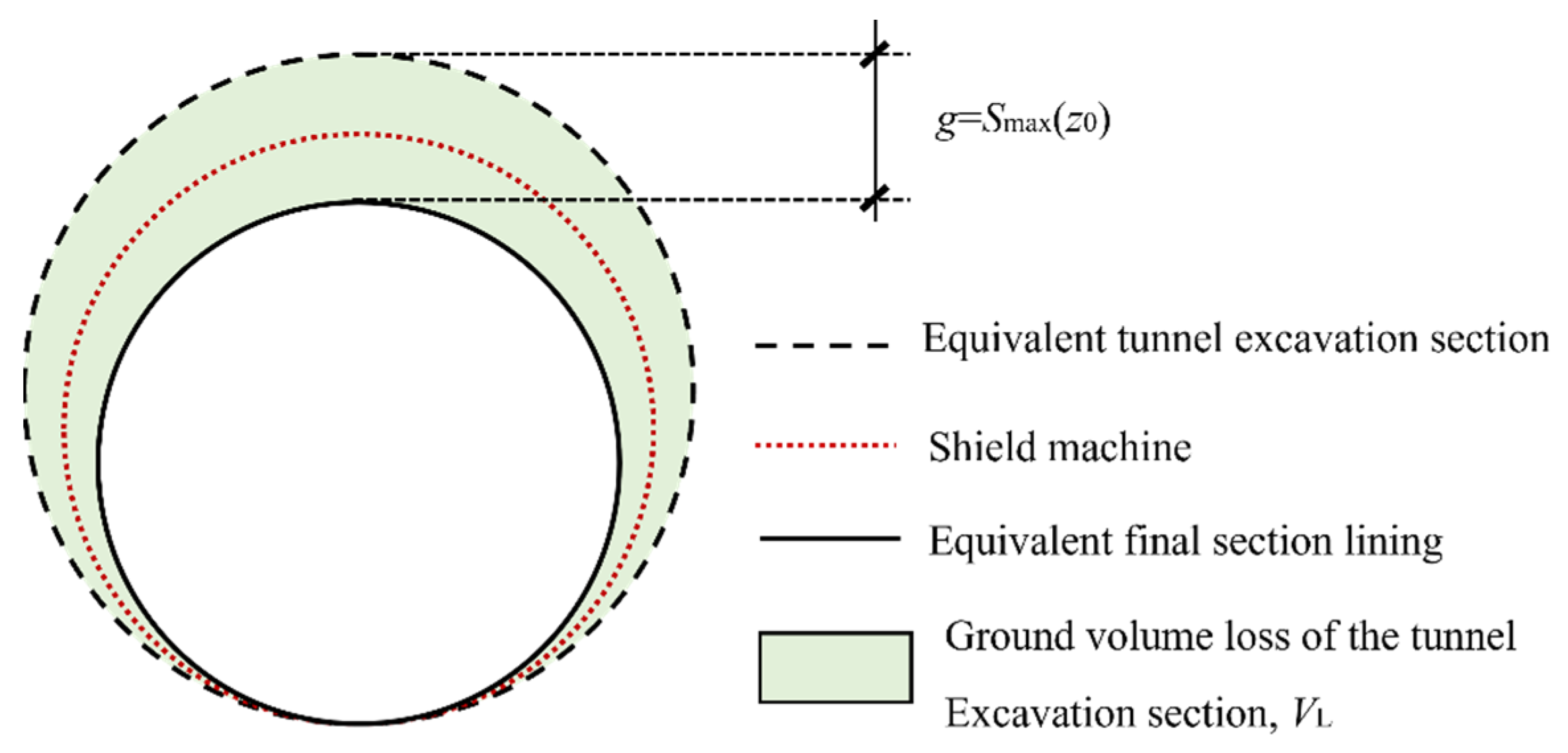
where D is the diameter of the new shield tunnel; i(0) is the settlement trough width at the ground surface, which can be estimated as 0.5 times the buried depth of the tunnel crown [39]; and VL is the ground loss rate due to tunneling, calculated by:
V L = 2 g D + g 2 D 2
where g is the gap parameter between the tunnel excavation section and the final tunnel lining section [38]. Deng et al. [53] have pointed out that the gap parameter can be decomposed into shield thickness and segment erection clearance, provided that the tunnel face soil is in mechanical equilibrium and yawing excavation is not considered. As illustrated in Figure 5, Smax(z0) corresponds to the gap parameter g, which can be calculated using Equation (33):
S max ( z 0 ) = D ( 1 1 V L )
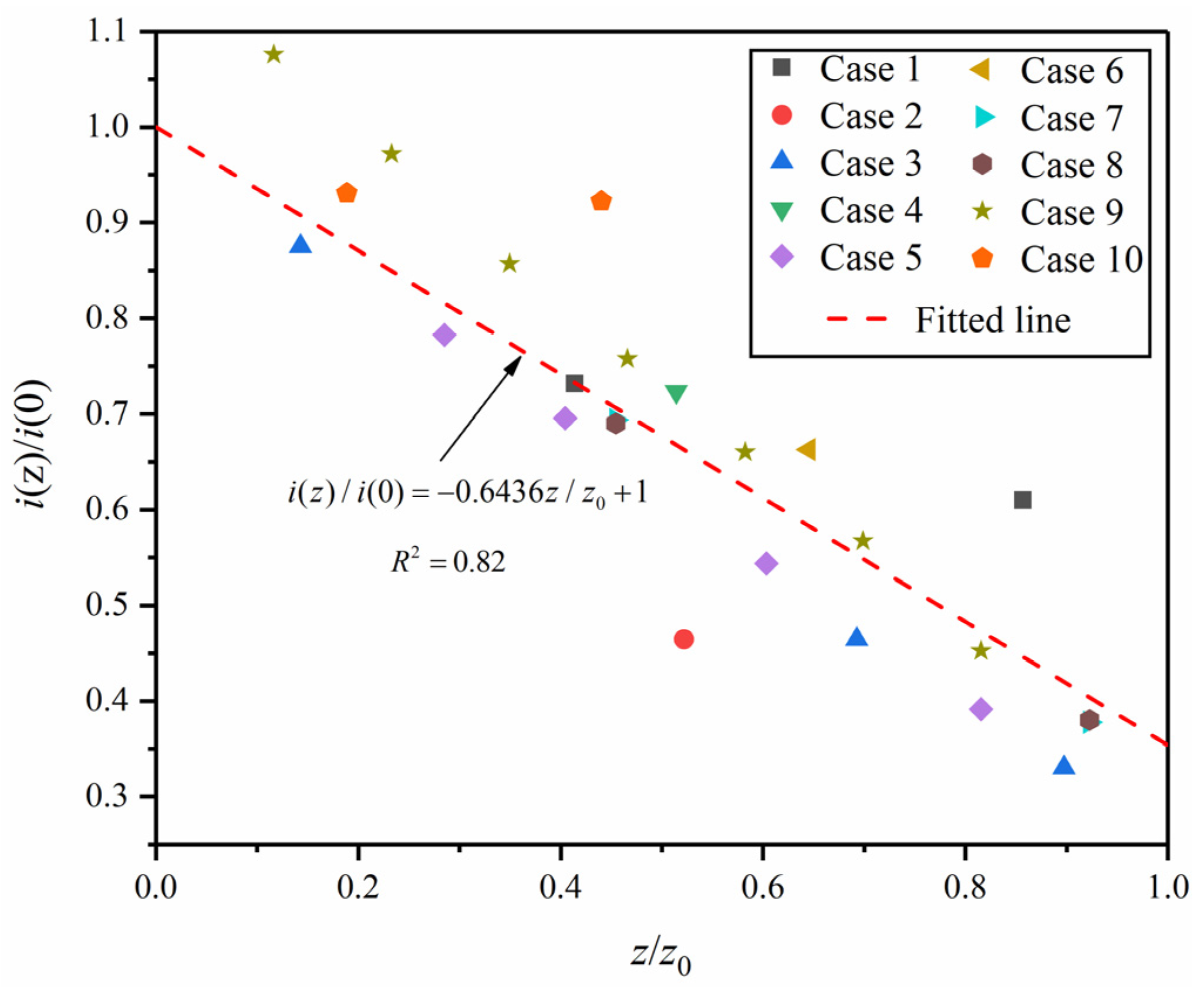
Once the settlement trough width i(z) is determined, Equation (31) can be solved, enabling the calculation of greenfield settlement at any arbitrary point. Therefore, this study establishes the relationship between the settlement trough width i(z) and depth z. Table 1 summarizes 10 sets of settlement trough widths from shield tunneling projects in clay areas, where new tunnels were constructed using closed-type shields (including earth-pressure-balance (EPB) and slurry shields). The data in Table 1 are plotted in Figure 6, with the dimensionless ratio i(z)/i(0) as the vertical coordinate and the normalized depth z/z0 as the horizontal coordinate. Figure 6 illustrates the correlation between i(z)/i(0) and z/z0, revealing that i(z)/i(0) and z/z0 exhibit an inverse proportional relationship. The relationship between i(z)/i(0) and z/z0 can be modeled by:
i ( z ) i ( 0 ) = 0.6436 z z 0 + 1
According to Han’s [39] study, the ground surface settlement trough width i(0) can be taken as 0.5z0, thus simplifying Equation (35) to:
i ( z ) = 0.3218 z + 0.5 z 0
Combining Equations (31), (32), (34) and (36), the greenfield settlement at point (x, z) induced by shield tunneling can be obtained as:
S ( x , z ) = D ( 1 1 V L ) ( α 1 ) ( 1 z z 0 ) α 0.97 + 1 exp ( x 2 2 ( 0.3218 z + 0.5 z 0 ) 2 )
α = 0.616 V L D z 0 ( 1 1 V L )
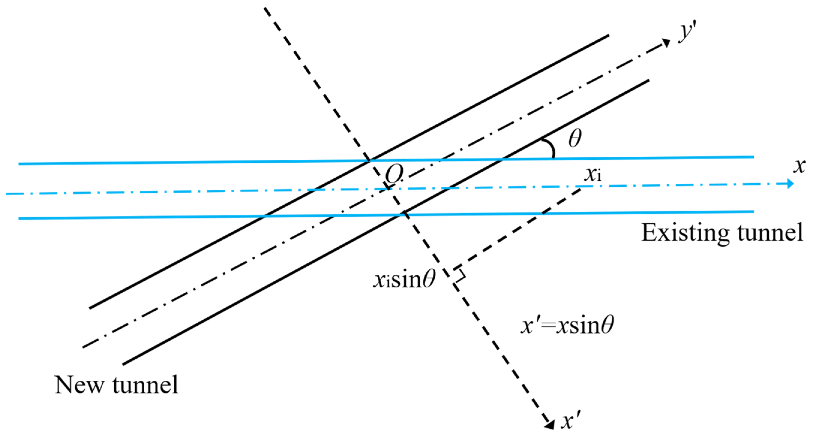
Considering that the constructing tunnel typically under-crosses the existing tunnel obliquely in most cases, a method of coordinate transformation is applied to solve this problem, as shown in Figure 7. Then, the existing tunnel settlement at point xi is equal to the point that is xisinθ away from the new tunnel’s centerline. Therefore, the term x in Equation (37a) can be replaced by xsinθ, where θ denotes the intersection angle between the new and existing tunnels [51,61]. Consequently, Equation (37a) is transformed into:
S ( x , z ) = D ( 1 1 V L ) ( α 1 ) ( 1 z z 0 ) α 0.97 + 1 exp ( ( x sin θ ) 2 2 ( 0.3218 z + 0.5 z 0 ) 2 )
Equation (38) can be readily computed solely based on the new tunnel diameter, ground loss rate, buried depth of the new tunnel crown, and the coordinates of the calculation point (x, z), eliminating the need for measured data. Thus, the greenfield settlement at the existing tunnel axis can be explicitly used as the input wCAT to investigate its impact on the existing tunnel caused by new tunnel excavation.

2.4. Simplification to the Winkler–Timoshenko Solution

It should be noted that Equation (26) can be simplified from the elastic continuum solution to the Winkler–Timoshenko solution when the continuum effect between soil elements is neglected, i.e., when λ s * is set to zero and 1/Gii in Equation (23) is defined as the stiffness of the Winkler foundation. Under this condition, Equation (23) can be expressed as:
K w = k , i = j 0 , i j
where k denotes the subgrade modulus of the Winkler foundation.
Then, Equation (26) can be undegraded as:
  ( S + K w S T + K w ) w b = K w w C A T
It indicates that the existing tunnel is simplified as a Timoshenko beam resting on a series of Winkler springs, as illustrated in Figure 8.
Vesic [62] derived the subgrade modulus of a Winkler foundation by equating the displacements and moments of an infinite beam resting on the ground surface (Winkler foundation) when subjected to concentrated loads. The solution for this equivalence is expressed as:
k Vesic = 0.65 E s D 4 E I 12 E s 1 υ s
where EI is the bending stiffness of the existing tunnel, and Es and υs denote the elastic modulus and Poisson’s ratio of the foundation soil, respectively.
Klar et al. [32] stated that the elastic continuum method is more conservative than the Winkler solution with Vesic’s [62] subgrade modulus when predicting the response of a pipeline subjected to new tunnel excavation, which is attributed to the aforementioned assumption. Yu et al. [63] proposed a novel method to predict the subgrade modulus for pipelines or tunnels buried at any depth of underground movements. The applicability of the Timoshenko beam model was validated by Liang et al. [64], and the modulus proposed by Yu et al. [63] is expressed as:
k Yu = 3.08 η E s 1 υ s 2 E s D 4 E I 8
η = 2.18 h / D 0.5 1 + 1 1.7 h / D h / D > 0.5

2.5. Equivalent Bending Stiffness and Shear Stiffness of the Existing Tunnel

The shield tunnel is composed of concrete segmental rings and circumferential joints, which are weaker than the former. The Timoshenko beam, as a continuous beam model, requires the weakness of circumferential joints to be considered when calculating bending and shear stiffnesses. Wu et al. [65] proposed a method for calculating the shear stiffness, expressed as:
( κ G A ) eq = ξ l s l b n b κ b G b A b + l s l b κ c G c A c
where ξ denotes the modification factor employed to account for the actual contact conditions between shield segments, which is set to 1 in the subsequent analysis [29]. κb and κc are the shear coefficients for bolts and segmental rings, with values of 0.9 and 0.5, respectively. Gb and Gc represent the shear moduli of bolts and the tunnel lining, respectively. Ab and Ac denote the cross-sectional areas of bolts and segmental rings, respectively. ls and lb signify the lengths of the tunnel segments and bolts, respectively.
Cheng et al. [19] proposed a method to calculate the equivalent bending stiffness, expressed as:
( E I ) eq = E c I c l s l s λ l b + λ l b ( cos φ + ( φ + π 2 ) sin θ ) / cos 3 θ
φ + cot φ = π ( 1 2 + n b E b A b E c A c )
where λ denotes the influencing factor of circumferential joints, taken as 0.4725 as proposed by Xu [66]; Ec and Ic represent the elastic modulus of the segmental lining and the area moment of inertia of the tunnel cross-section, respectively. nb is the number of steel bolts connecting segmental rings, and φ is the angle of the neutral axis.
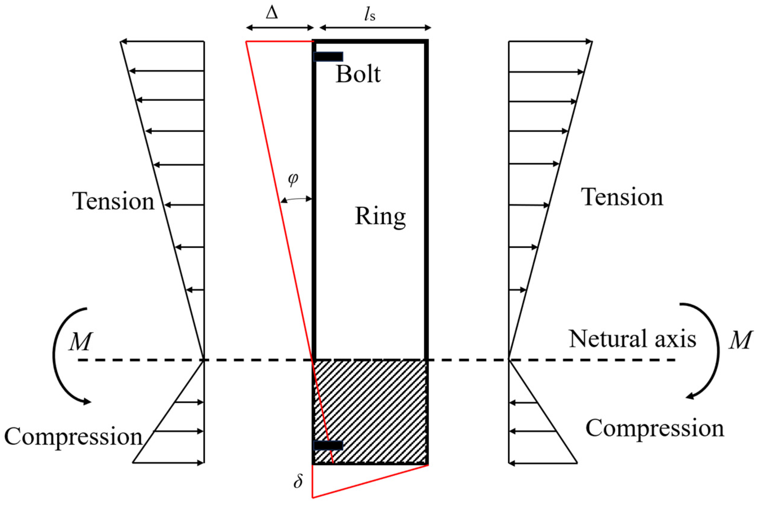
The applicability of both Equation (43) and Equation (44) has been validated to predict the deformation of existing tunnels induced by tunneling [19,29,67]. As shown in Figure 9, the segment deformation mode is explained according to Liang et al.’s research [29]. Based on the research, the joint opening and segmental dislocation can be derived from the geometric relationship, with their expressions given as follows:
Δ = M ( E I ) eq ( R + R sin θ ) l s
δ = l s tan Q ( κ G A ) eq

3. Verification

3.1. Case 1: Shenzhen Metro Line 1 Under-Crossed by Line 9

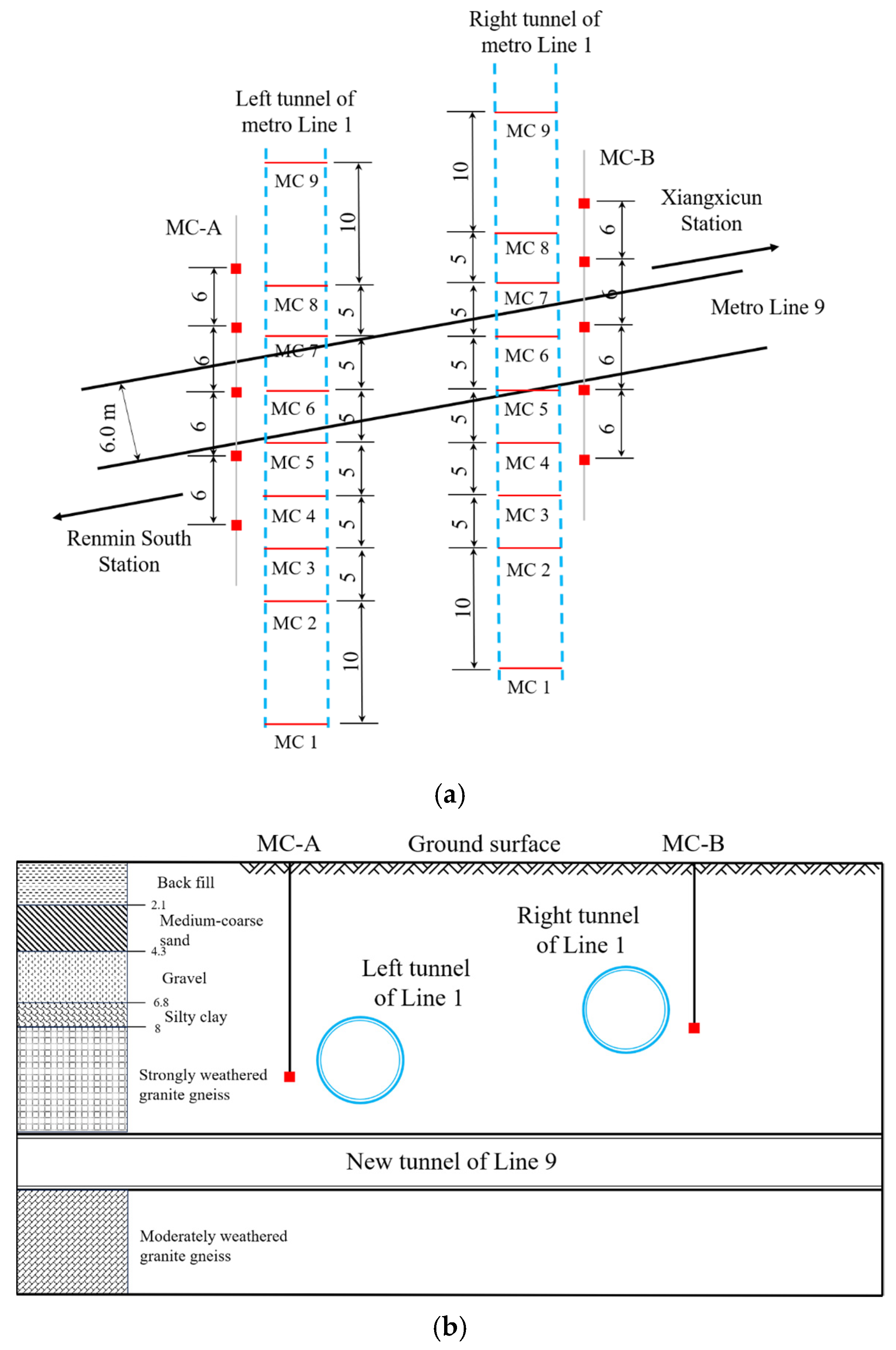
In this study, the deformation response of the existing Shenzhen Metro Line 1 tunnel to the closely under-crossing Metro Line 1 shield tunnel is analyzed. The existing Line 1 tunnels were excavated using an earth pressure balance (EPB) shield, with the segmental lining possessing external and internal radii of 3.0 m and 2.7 m, respectively, and each segment lining being 1.5 m in length. All segmental lining parameters are summarized in Table 2. The intersection angle between the new and existing tunnels is approximately 85°, and the burial depths of the new tunnel, existing right tunnel, and left tunnel are 15.6 m, 8.1 m, and 10.8 m, respectively. The project plan and cross-section are shown in Figure 10. Additionally, the soil physical parameters are provided in Jin et al.’s [68] research. As illustrated in Figure 10, the monitoring points for the existing tunnels are spaced 5.0–10.0 m apart. Meanwhile, a greenfield area 2.0 m away from the existing tunnels is monitored to ensure the safe operation of Line 1. The monitoring point layout, with adjacent points 6.0 m apart, is also depicted in Figure 10.
Considering that the length of each segmental lining in the existing tunnel is 1.5 m, the distance between two adjacent computational nodes is set to 1.5 m (l = 1.5 m), with a calculated length of 180 m (L = 180 m). Thus, the entire existing tunnel is divided into 121 nodes (n = 120 segments). The equivalent longitudinal bending stiffness and shearing stiffness are calculated using Equations (43) and (44), yielding values of 1.52 × 10⁵ MN∙m2 and 1.18 × 10³ MN, respectively. In addition, based on the back analysis method of Jin et al.’s [68] research, the ground loss rates for the existing left and right tunnels are taken as 0.36% and 0.32%, respectively. The multiple soil layers are transformed into a homogeneous soil using the equivalent layer method, where the Poisson’s ratios and elastic moduli of all soil layers are equalized to the clay layer [69]. The subgrade moduli calculated according to Vesic’s [62] and Yu et al.’s [63] research are 8.43 × 10³ kN/m and 2.74 × 10⁴ kN/m, respectively.
Figure 11 shows the calculated greenfield settlement based on the modified Gaussian curve in this study and the tunnel settlement computed using the elastic continuum and Winkler solutions. Notably, the greenfield settlement predicted by this study aligns well with the measured data. Using the same greenfield settlement prediction, the elastic continuum solution and Winkler solution are compared for different subgrade moduli. The results indicate that the elastic continuum solution slightly underestimates the settlement in the existing left tunnel but matches the measured settlement in the right tunnel. In contrast, both Winkler–Timoshenko solutions (based on Vesic’s and Yu et al.’s subgrade moduli) obviously underestimate the settlement in both left and right tunnels. These findings agree with Klar et al. [32], who concluded that the elastic continuum solution is more conservative than the Winkler solution for predicting pipeline responses to tunneling. Comparing calculations using Yu et al.’s and Vesic’s subgrade moduli shows that Yu et al.’s method improves the accuracy of tunnel displacement prediction. However, it should be noted that the Winkler solution yields a significantly wider tunnel settlement trough than both the elastic continuum solution and measured data. Additionally, abnormal bulges are observed on both sides of the new tunnel centerline, which contradict the deformation behavior reported in actual engineering cases of existing tunnels.
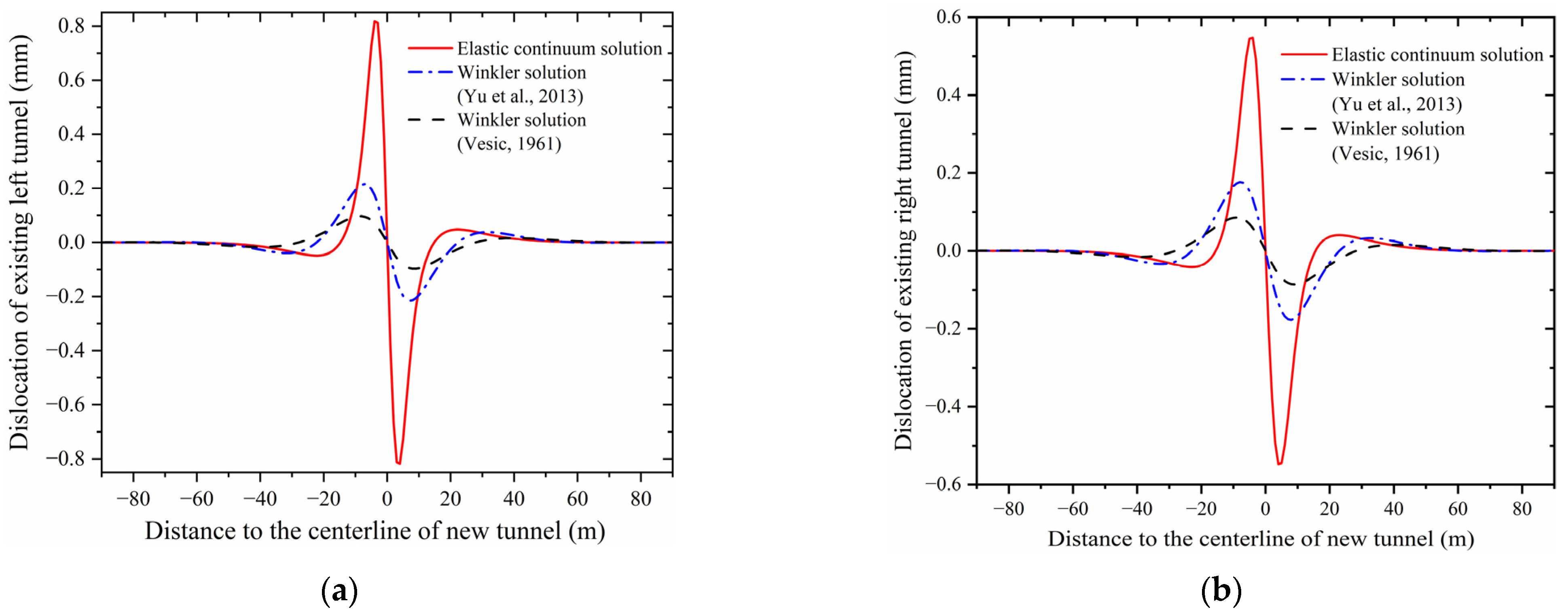
The longitudinal distributions of the joint openings obtained from the elastic continuum method and the Winkler–Timoshenko solution are shown in Figure 12. It can be observed that the Winkler solution significantly underestimates the positive opening (opening occurring at the invert of the existing tunnel) and slightly underestimates the negative opening (opening occurring at the crown of the existing tunnel). As the parameter that has a positive correlation with the bending moment in the existing tunnel, the opening of joints indicates that the bending moment of the area, which is near the new tunnel centerline, may be significantly underestimated when using the Winkler solution. As depicted in Figure 12, the underestimation of the opening when using the Winkler solution may be more than 50% when compared to the elastic continuum solution.
Figure 13 illustrates the distribution of adjacent segmental dislocations when comparing the elastic continuum and Winkler solutions. Similar to the joint openings, the Winkler–Timoshenko solution significantly underestimates segmental dislocations. This discrepancy arises because the Winkler foundation model cannot account for the continuity of foundation soil, potentially leading to errors in predicting both segmental dislocations and shear forces in the existing tunnels. Although Yu et al. [63] revised the Winkler subgrade modulus, their prediction values, while larger than those from the Vesic modulus Winkler solution, still exhibit errors compared to the elastic continuum method.

3.2. Case 2: Shenzhen Metro Line 3 Under-Crossed by Line 9

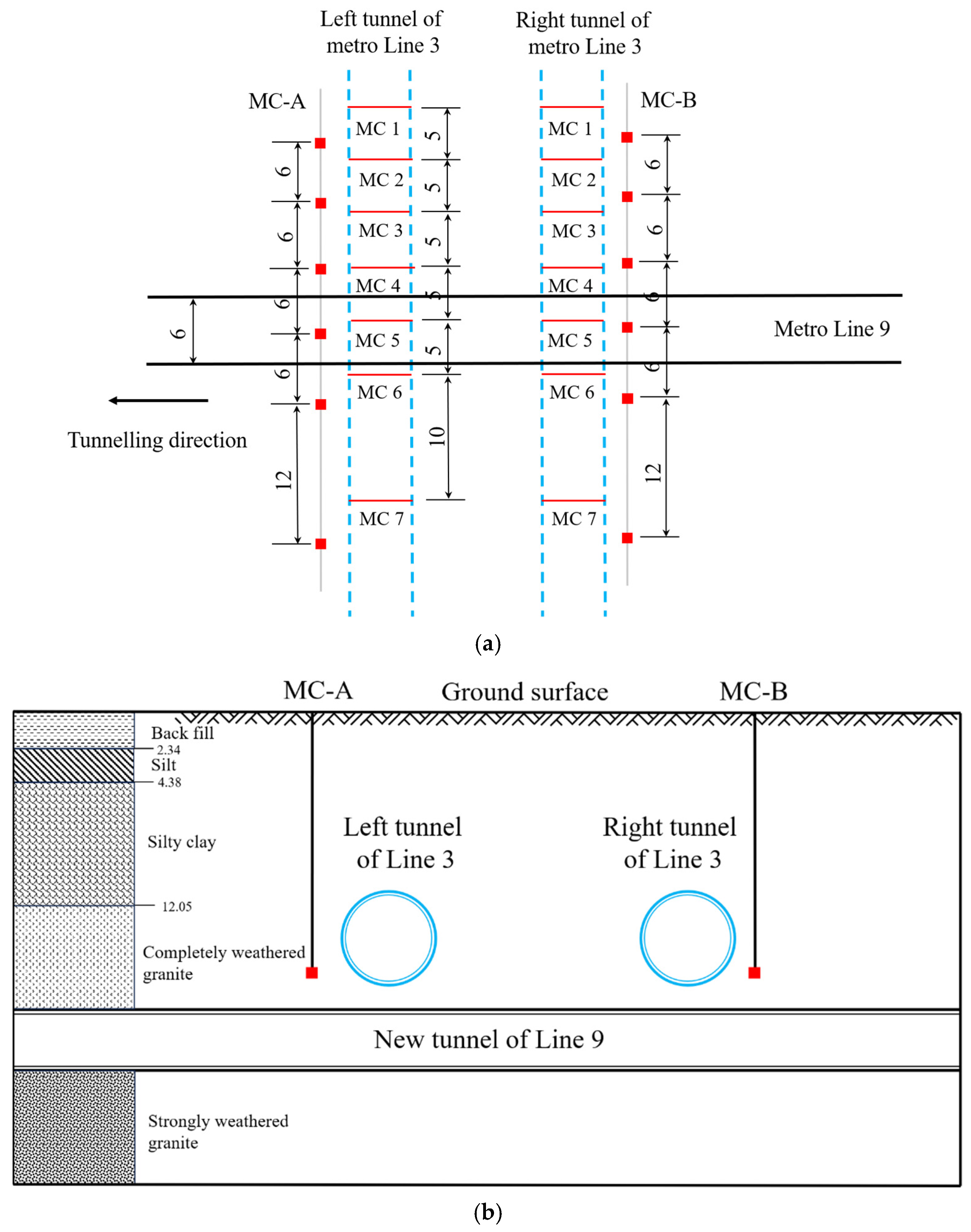
Another engineering case reported by Jin et al. [68], where the existing Metro Line 3 is under-crossed by the new Metro Line 9, is used to validate the proposed method in this study. In this case, the existing tunnels were also excavated using an earth pressure balance (EPB) shield, with the segmental lining possessing an external diameter of 6.0 m and a thickness of 0.3 m. Other parameters related to the existing tunnel are consistent with Case 1. The new tunnel was similarly excavated by an EPB shield, with its axis buried at a depth of 21.0 m. The tunneling direction is perpendicular to the existing tunnels, and the clearances between the new tunnel and the existing tunnels are approximately 1.5 m. Greenfield settlements near the existing tunnels were also monitored, with the layout of monitoring points (MC-A and MC-B) shown in Figure 14. Additionally, two monitoring sections (MC1–MC7) were arranged along the existing left and right tunnels to measure tunnel settlement. Both greenfield and existing tunnel settlement monitoring results are presented in Figure 15. Using Equations (43) and (44), the equivalent bending and shearing stiffnesses of the existing tunnel are calculated to be 1.52 × 10⁵ MN∙m2 and 1.18 × 10³ MN, respectively. The subgrade moduli of the Winkler model based on Vesic’s research and Yu et al.’s research are valued as 1.15 × 10⁴ kN/m and 4.16 × 10⁴ kN/m, respectively. Jin et al. adopted the back analysis and obtained the ground losses of the existing left and right tunnels due to new tunnel excavation, which are equal to 0.23% and 0.21%, respectively [68].
Figure 15 illustrates the comparison of greenfield settlement derived from the modified Gaussian formula and measured data for both existing left and right tunnels. The results show that the measured greenfield settlement can be effectively fitted by the modified Gaussian formula proposed in this study. Figure 15 also depicts the comparison of existing tunnel settlements calculated using the elastic continuum and Winkler solutions against measured data. Under-cross tunneling usually results in a narrow and deep greenfield settlement, while the existing tunnel settlement curves prefer to be wider and shallower. The reason is that the stiffness contrast between the existing tunnel and the surrounding soil causes the tunnel structure to resist deformation. Notably, the maximum settlement of the existing tunnel is smaller than that of the greenfield. It should be noted that the settlement difference reflects the soil–tunnel interaction according to the elastic continuum solution: the area where the tunnel deformation is larger than greenfield settlement indicates an increasing soil pressure in this area, while a decreasing soil pressure exists where the tunnel deformation is less than the greenfield settlement. By comparing the elastic continuum and Winkler solutions with measured data, it is evident that the elastic continuum solution based on the modified Gaussian formula provides a reasonable evaluation of existing tunnel settlement under tunneling influence.

3.3. Case 3: Shanghai Metro Line 4 Under-Crossed by Line 11

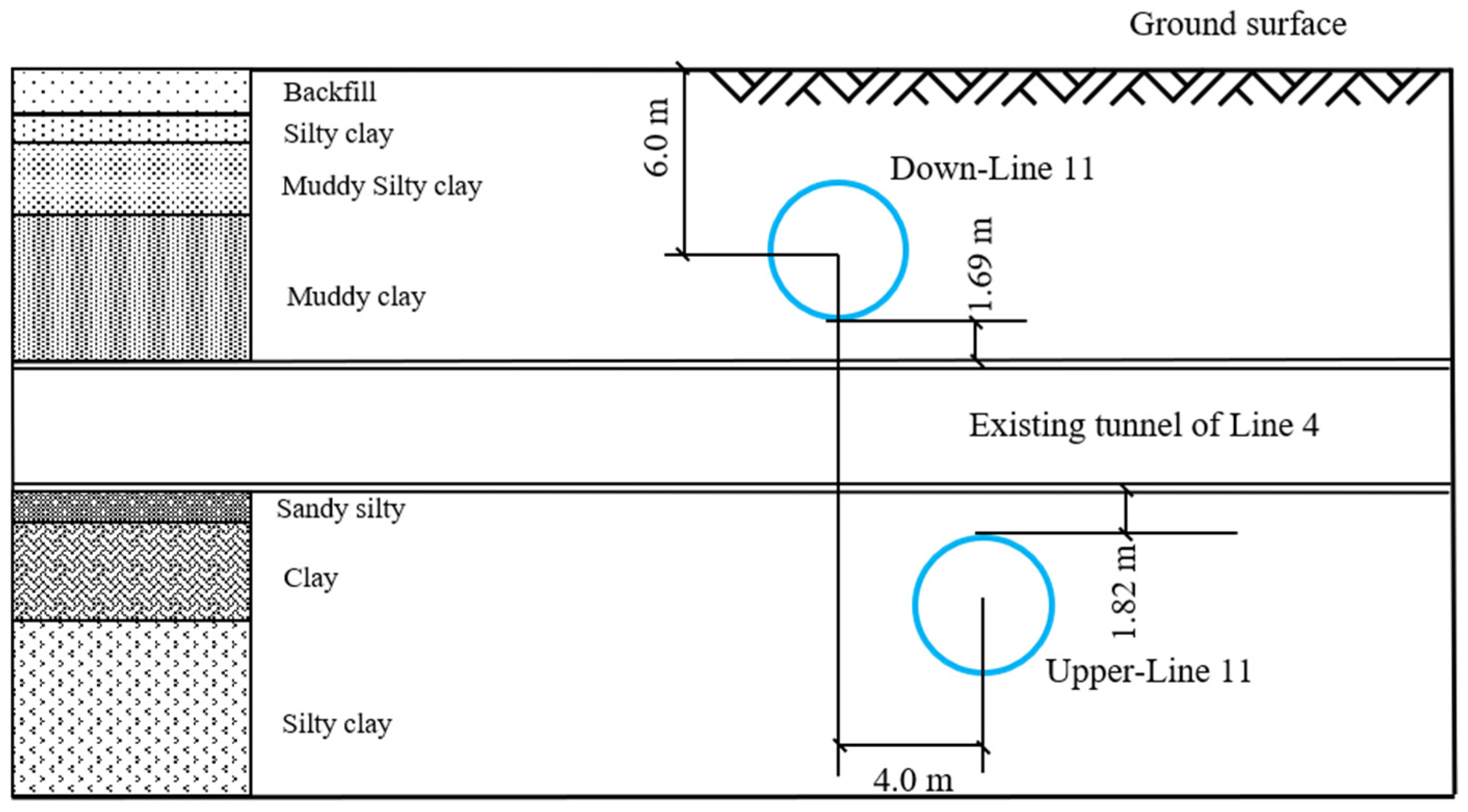
To validate the proposed method with regard to predicting existing tunnel deformation, another case reported by Zhang and Huang [10] is analyzed. In this engineering case, the existing tunnel of Metro Line 4 is under-crossed by the upper line of Metro Line 11, and the cross-section view of this project is shown in Figure 16. The burial depths of the new and existing tunnel centerlines are 25.1 m and 17.1 m, respectively. The intersection angle between the new and existing tunnels is 75°. The related parameters of the existing tunnel are listed in Table 3. The bending stiffness and shearing stiffness are calculated to be 1.6 × 10⁵ MN∙m2 and 2.02 × 10³ MN, respectively. Considering the existing tunnel is located in clay soil, the elastic modulus of the foundation soil is taken as 20.1 MPa, and the ground loss due to the new tunnel excavation is 0.25%. Adopting Vesic’s method and Yu et al.’s model, the Winkler subgrade moduli are valued as 1.56 × 10⁴ kN/m and 5.7 × 10⁴ kN/m, respectively.
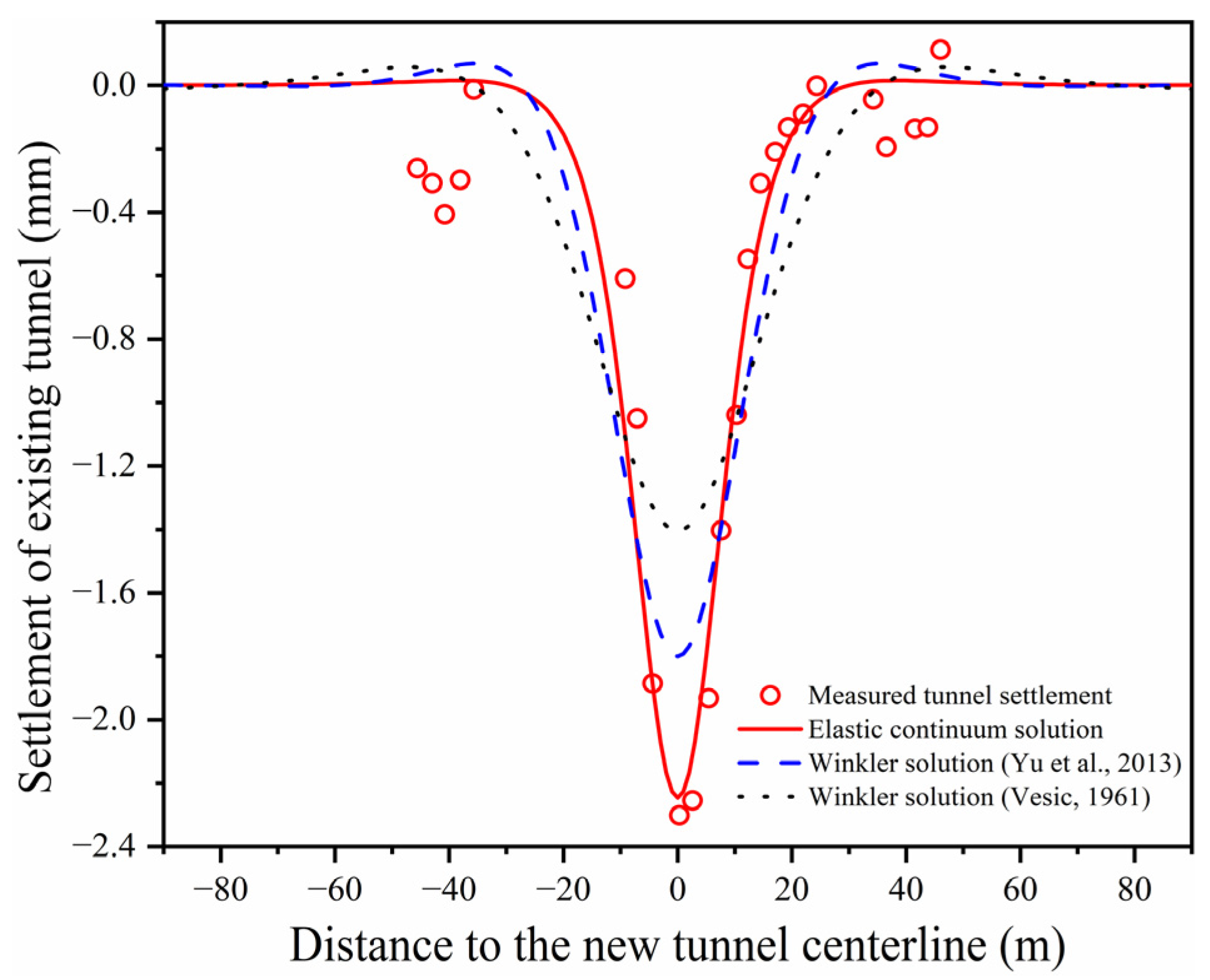
Figure 17 shows the calculated existing tunnel deformation using the proposed method and Winkler models versus measured data. The existing tunnel deformation calculated using the proposed method has a good fit with the measured data, while that of the Winkler model (including Vesic’s method and Yu et al.’s method) is less than the measured data. In addition, both tunnel settlement curves based on the Winkler model show abnormal bulges on both sides of the new tunnel centerline, just like in Case 1. Based on the above findings, the proposed method based on the soil–tunnel interaction has an advantage in modeling existing tunnel deformation behavior under the influence of under-crossing tunneling.

4. Parametric Analysis

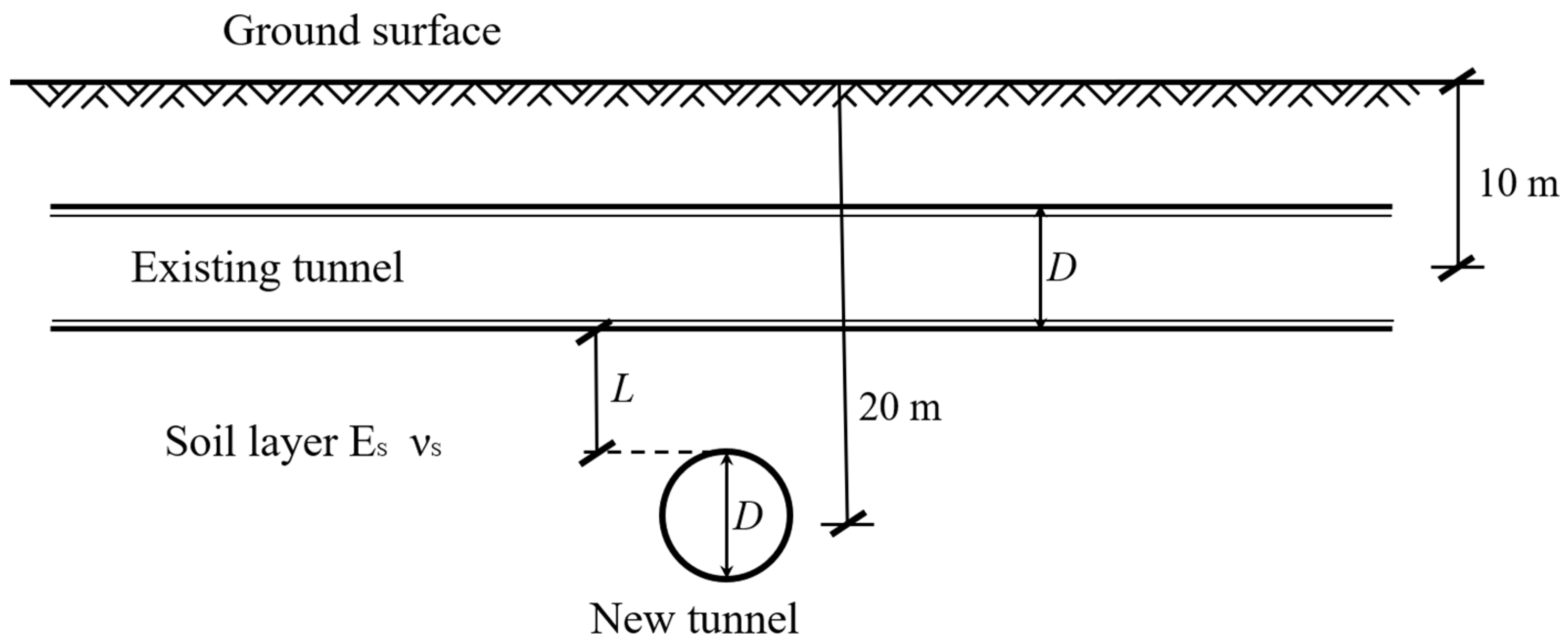
In the previous section, the rationality of the proposed semi-analytical method was validated using measured data from two engineering cases. To further investigate the mechanism by which new tunnel construction impacts the deformation behavior and internal force distribution of existing tunnels, a series of parameters are analyzed: the ground loss rate, intersection angle, tunnel–soil stiffness factor, and vertical clearance. The positions of the new and existing tunnels are shown in Figure 18. The equivalent bending and shear stiffnesses of the existing tunnel are identical to those in Case 1. It is assumed that the tunneling direction is perpendicular to the existing tunnel. Other parameters related to the shield, soil layers, and existing tunnel are listed in Table 4.

4.1. Influence of the Ground Loss Rate

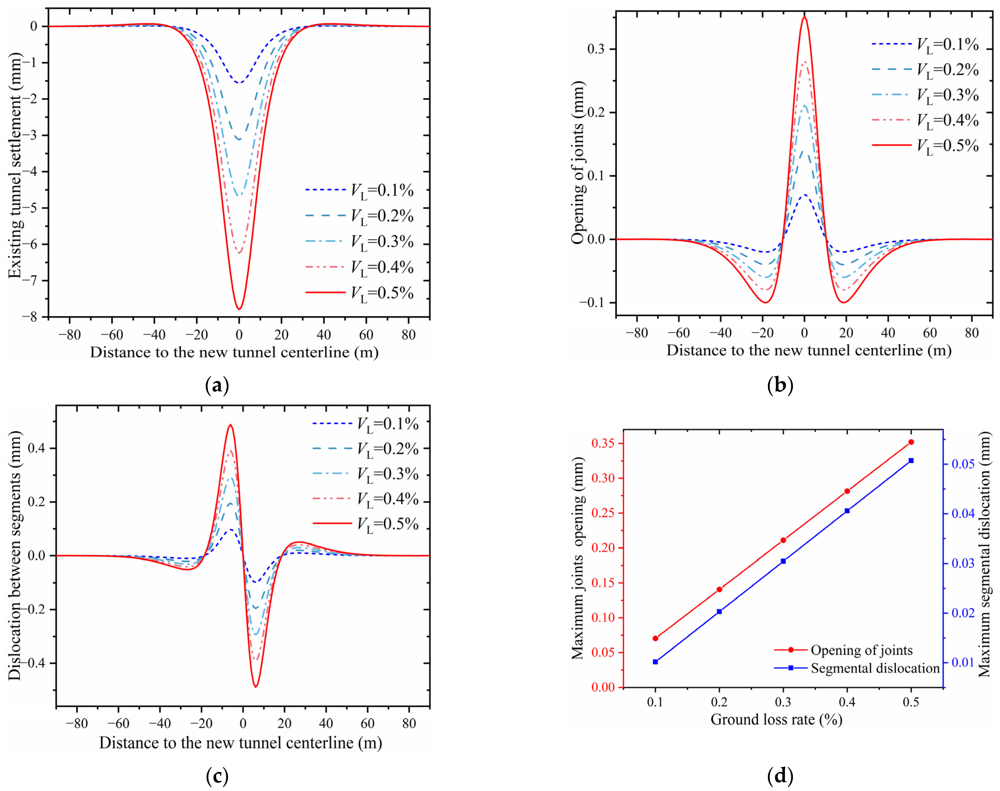
Figure 19a shows the existing tunnel settlement for ground loss rates ranging from 0.1% to 0.5%. Notably, the normalized tunnel settlements increase significantly with the ground loss, while the widths of settlement troughs remain nearly unchanged for different ground losses. Figure 19b presents the joint openings of the existing tunnel under different ground losses. It shows that both positive (invert openings) and negative (crown openings) values correlate positively with ground loss, indicating that increases in the ground loss will result in larger sagging and hogging bending moments of the existing tunnel. Specifically, positive openings increase more significantly than negative ones, reflecting that maximum hogging bending moments grow more rapidly than sagging moments with ground loss. The maximum positive opening typically occurs at the new tunnel’s centerline, whereas the maximum negative opening is located approximately ±3D from this centerline. Figure 19c depicts segmental dislocations versus ground loss, showing that maximum positive and negative dislocations both occurred at the new tunnel boundary. Meanwhile, segmental dislocations increase consistently with ground loss, matching the trend observed in joint openings. Figure 19d shows the trend of both maximum opening and dislocation with the increase in ground loss, indicating that a positive correlation exists between both maximum opening and dislocation and ground loss. Thus, selecting a proper tunneling method depending on the soil’s properties and minimizing ground loss can effectively reduce the existing tunnel settlement, opening, and dislocation and protect the existing tunnel from the destruction of segmental joints.

4.2. Influence of the Intersection Angle

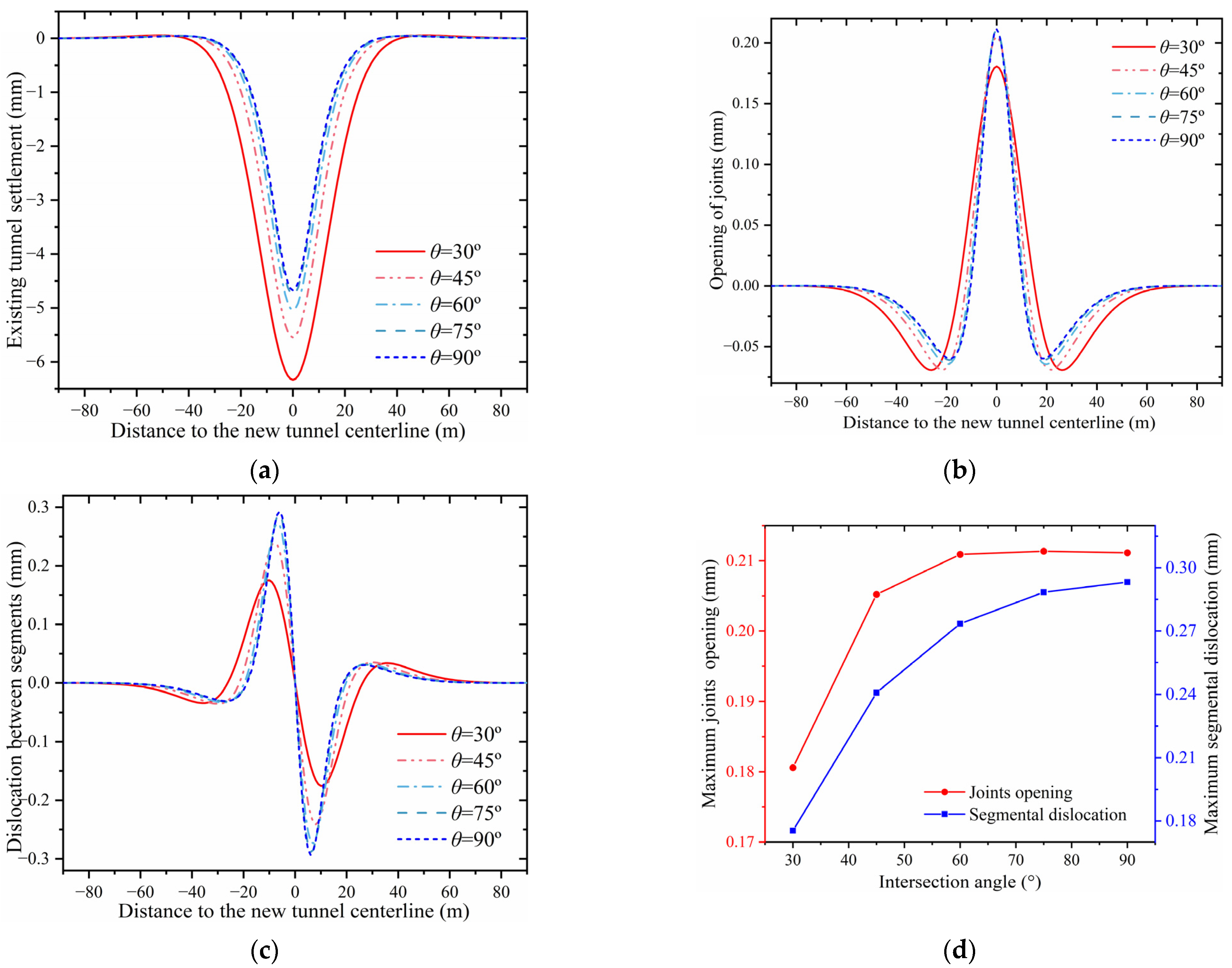
Figure 20a shows the tunnel settlements with intersection angles from 30° to 90°, indicating that both the magnitude and width of the existing tunnel settlement increase with decreasing intersection angles, likely due to the expanded disturbance zone caused by smaller angles. Thus, under-cross tunneling the existing tunnel with a large angle is an effective measure for reducing the existing tunnel settlement results from new tunnel excavation. Figure 20b presents the joint openings of the existing tunnel at different intersection angles. It shows that positive joint openings usually occur at the area where the new tunnel centerline is located, while the negative openings prefer to be ±2D away from this centerline. Furthermore, it shows that positive joint openings at the new tunnel centerline exhibit an increasing trend, while negative openings remain unchanged. Meanwhile, the minimum joint opening prefers to be away from the new tunnel centerline with a decrease in the intersection angle. Figure 20c shows the segmental dislocation at different intersection angles, revealing a pronounced increase in both positive and negative segmental dislocations as the intersection angle decreases. Moreover, both locations of maximum positive and negative dislocation are observed to be away from the new tunnel centerline. Figure 20d depicts the maximum opening and dislocation versus the intersection angle, which indicates that a smaller intersection angle would result in a slighter joint deformation (including joint openings and segmental dislocation), in which the segmental dislocation is more sensitive. The above analysis indicates that arranging the tunneling direction properly could reduce the risk of segmental joints in existing tunnels under the influence of under-cross tunneling and clarify the reinforcing area of the existing tunnel.

4.3. Influence of the Tunnel–Soil Stiffness Factor

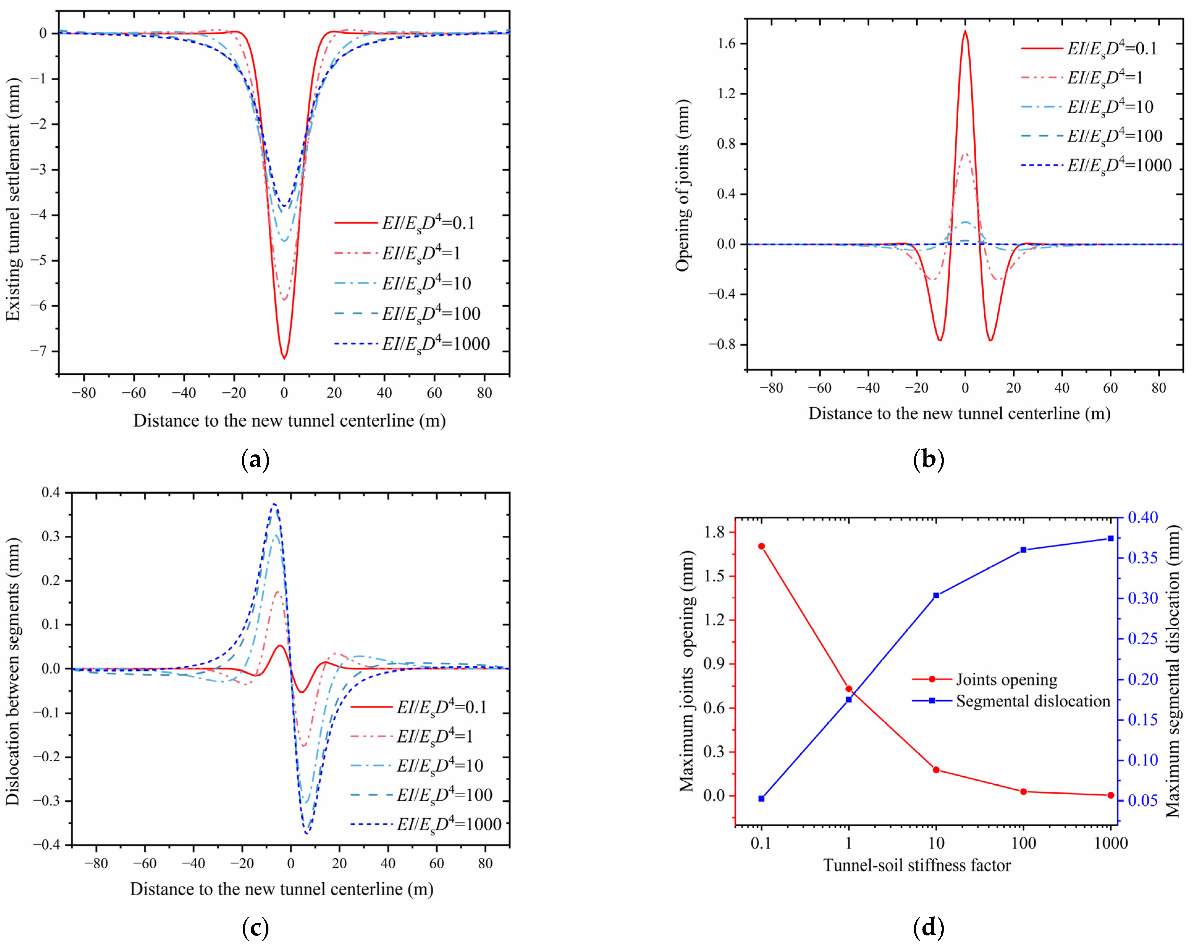
The deformation behavior of the existing tunnel depends not only on new tunnel construction factors but also on the tunnel–soil interaction, indicating that the relative tunnel–soil stiffness significantly influences existing tunnel deformation [43]. When the tunnel bending stiffness is similar to the soil stiffness, the existing tunnel tends to deform with the soil; conversely, it resists soil deformation when its stiffness notably exceeds the soil stiffness. Similar to Klar et al. [32,33], the tunnel–soil stiffness factor, E I / E s D t 4 , is defined as the ratio of bending stiffness to soil stiffness. Figure 21a shows tunnel settlement profiles for stiffness factors of 0.1, 1, 10, 100, and 1000. As the stiffness factor decreases, the existing tunnel stiffness is closer to the foundation soil, and the existing tunnel prefers to be deformed with the surrounding soil. Specifically, the settlement profile width narrows, while maximum settlements increase significantly. In contrast, the existing tunnel prefers to resist the soil deformation at a high stiffness factor, and the settlement profile of the existing tunnel is wider and shallower. It indicates that more upper-soil pressure is transformed to wider foundation soil, while a decreasing soil pressure is observed at the new tunnel centerline area. Figure 21b,c depict joint openings and segmental dislocations for different stiffness factors. The joint deformations are dominated by opening deformations when the stiffness factor is low. As the stiffness factor increases, the joint openings decrease while the dislocation increases significantly. Notably, while the maximum positive opening remains above the new tunnel centerline, the location of the maximum negative opening approaches the new tunnel boundary as the stiffness factor decreases. This indicates that the existing tunnel transitions from bending-dominated to shear-dominated deformation as the stiffness increases, and vice versa. Meanwhile, similar phenomena are observed in maximum positive/negative dislocations. Furthermore, the relationship between the maximum opening and dislocation and the stiffness factor is plotted in Figure 21d, confirming that the existing tunnel is dominated by bending moments at a low stiffness factor and that the existing tunnel deformation mode is dominated by shear, as mentioned above. Thus, calculating the tunnel–soil stiffness factor is essential to determine whether to prioritize measures for joint openings or segmental dislocations to prevent damage to segmental joints and minimize the disturbance to the existing tunnel.

4.4. Influence of the Vertical Clearance Between the New and Existing Tunnels

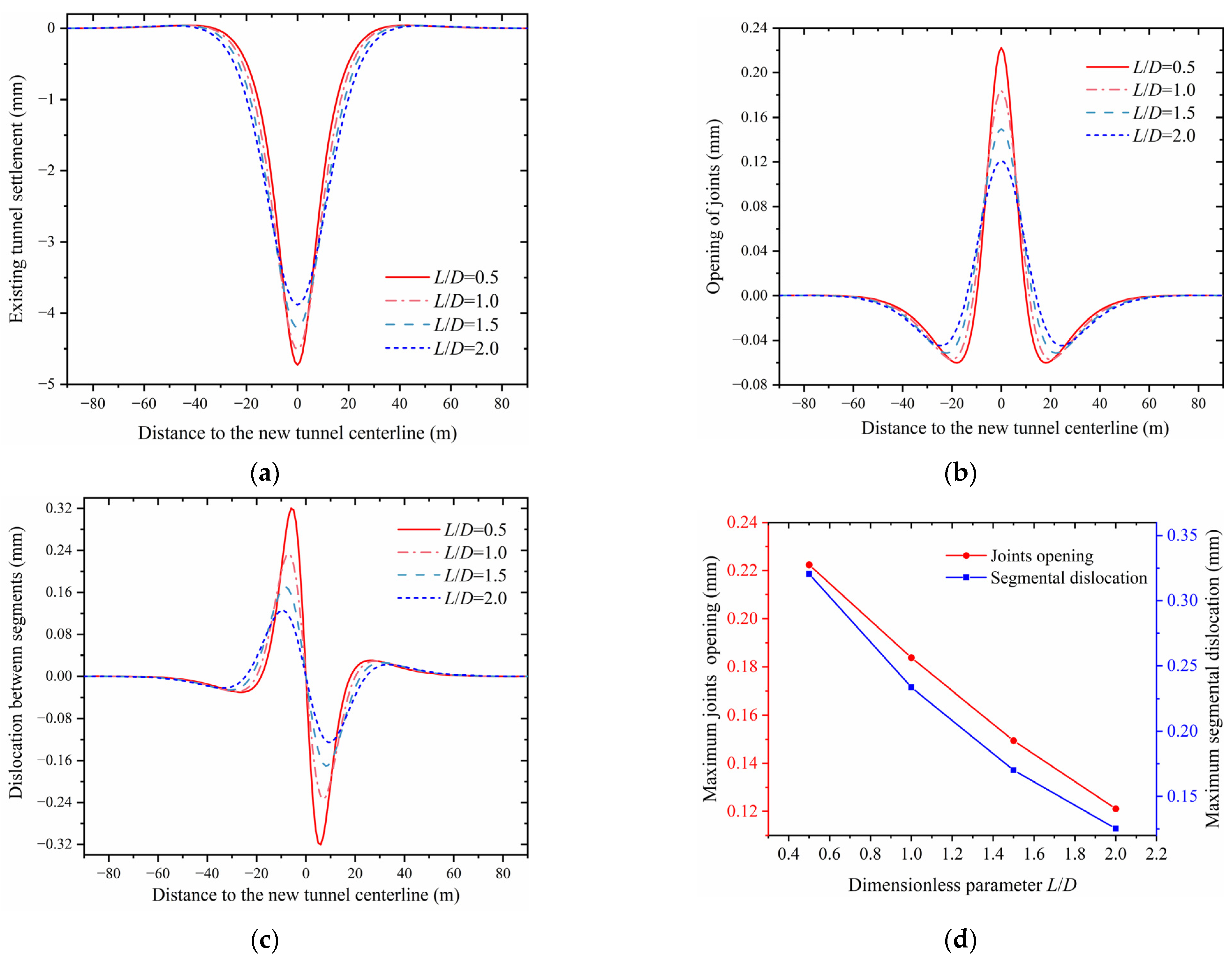
The vertical clearance between the new and existing tunnels, as a key relative position parameter, significantly influences the existing tunnel’s structural response to new tunnel excavation. Here, the vertical clearance is normalized by the new tunnel diameter D, with the ratio L/D varying from 0.5 to 2.0. Figure 22a gives the existing tunnel settlement profiles at different vertical clearances. It shows that as the vertical clearance decreases, the tunnel settlement curve becomes narrower and deeper. It indicates that the tunneling-induced soil disturbance rapidly intensifies as the new tunnel depth approaches the existing tunnel centerline. At this time, additional loads caused by the excavation of the new tunnel are undertaken by the existing tunnel located in the area of the new tunnel centerline. In contrast, the additional load is transformed to a wider range of existing tunnels. Figure 22b,c illustrate the segmental joints’ deformation behavior, including joint openings and segmental dislocations, under varying vertical clearances, respectively. Notably, as L/D decreases (i.e., vertical clearance reduces), the maximum positive joint openings increase while the maximum negative opening shows negligible change. Thus, decreasing the vertical clearance has a significant impact on the existing tunnel located at the new tunnel’s centerline area, which may even result in segmental bolt yielding. Additionally, maximum positive/negative segmental dislocations are both observed at the new tunnel boundary and significantly increase with the vertical clearance from 2.0D to 0.5D. Moreover, the trend of both maximum opening and dislocation with the ratio L/D from 0.5 to 2.0 is shown in Figure 22d. It is obvious that a negative correlation exists between both the joint opening and segmental dislocation and vertical clearance. Thus, arranging the depth of the new tunnel centerline properly as an economical measure at the initial design stage can prevent the existing tunnel from structural destruction to the maximum extent.

5. Conclusions

This study proposes an elastic continuum method based on a modified Gaussian function to predict the deformation behavior of existing tunnels under tunneling influence. Parametric analyses are conducted to investigate critical parameter effects, yielding the following conclusions:
(1)
The proposed elastic continuum method considers the tunnel–soil interaction, unlike the degrading Winkler–Timoshenko method. The modified Gaussian function is validated by measured greenfield settlement data. Compared with the elastic continuum solution, the Winkler model significantly underestimates both joint openings and segmental dislocations;
(2)
Existing tunnel deflection, maximum joint opening, and segmental dislocation strongly depend on the ground loss rate, exhibiting a positive correlation. Conversely, an inverse relationship is observed with the intersection angle: a larger intersection angle leads to a broader and more pronounced tunnel settlement profile, indicating that the disturbance zone expands as the intersection angle increases. Thus, under-crossing existing tunnels at a large intersection angle and selecting appropriate shield types based on ground conditions to minimize soil disturbance are preconditions for ensuring the safe operation of existing metro lines;
(3)
The tunnel–soil stiffness factor analysis reveals that the existing tunnel deformation mode transitions to bending-dominated as the stiffness factor decreases, whereas it becomes shear-deformation-dominated with increasing stiffness factor. Additionally, decreasing vertical clearance leads to marginal changes in tunnel settlement but induces significant growth in both maximum joint openings and segmental dislocations. Therefore, adopting different reinforcement measures for varying foundation soil conditions and ensuring a reasonable arrangement of the new tunnel position are cost-effective strategies to prevent existing tunnel diseases.
The proposed method in this paper has achieved good fitting results with measured data and has an advantage in calculating the existing tunnel deformation compared to conventional models. However, it should be noted that the proposed method in this paper only takes into account the elastic behavior of foundation soil, which may exhibit nonlinear mechanical behavior at large deformations. Moreover, segmental joints prefer to display nonlinear characteristics at large deformations and need to be studied further in the future.

Author Contributions

Conceptualization, H.Z. and W.W.; methodology, H.Z., L.L., C.H., R.L. and W.W.; Software, H.Z., A.A.H.S.H., L.L., C.H., D.H. and W.W.; validation, H.Z., D.H. and W.W.; formal analysis, H.Z., L.L., C.H. and W.W.; investigation, H.Z., A.A.H.S.H., L.L., C.H., D.H., R.L. and W.W.; resources, L.L., C.H., D.H. and W.W.; data curation, H.Z., A.A.H.S.H., C.H., D.H. and R.L.; writing—original draft preparation, H.Z., R.L. and W.W.; writing—review and editing, R.L. and W.W.; visualization, H.Z., A.A.H.S.H., L.L., C.H. and D.H.; supervision, W.W.; project administration, W.W.; funding acquisition, W.W. All authors have read and agreed to the published version of the manuscript.

Funding

This research is supported by the National Natural Science Foundation of China (Grant No. 52178371, 52168046, 52178321). The Research Project of the Engineering Research Centre of Rock-Soil Drilling & Excavation and Protection, Ministry of Education (Grant No.202305), the Science and Technology Project of Zhejiang Provincial Communication Department (202305-2), and the Construction Research Founds of Department of Housing and Urban-Rural Development of Zhejiang Province (Grant No. 2021K256) are also acknowledged.

Data Availability Statement

Data are available on request from the authors.

Conflicts of Interest

Authors Lv Liu, Chaoqun Huang and Dong Huang were employed by the company Wuhan Municipal Construction Group Co., Ltd. The remaining authors declare that the research was conducted in the absence of any commercial or financial relationships that could be construed as a potential conflict of interest.

References

  1. Verruijt, A.; Booker, J.R. Surface Settlements Due to Deformation of a Tunnel in an Elastic Half Plane. Geotechnique 1996, 46, 753–756. [Google Scholar] [CrossRef]
  2. Loganathan, N.; Poulos, H.G. Analytical Prediction for Tunneling-Induced Ground Movements in Clays. J. Geotech. Geoenviron. Eng. 1998, 124, 846–856. [Google Scholar] [CrossRef]
  3. Vorster, T.E.B.; Klar, A.; Soga, K.; Mair, R.J. Estimating the Effects of Tunneling on Existing Pipelines. J. Geotech. Geoenviron. Eng. 2005, 131, 1399–1410. [Google Scholar] [CrossRef]
  4. Pinto, F.; Whittle, A.J. Ground Movements Due to Shallow Tunnels in Soft Ground. I: Analytical Solutions. J. Geotech. Geoenviron. Eng. 2014, 140, 04013040. [Google Scholar] [CrossRef]
  5. Franza, A.; Marshall, A.M.; Zhou, B. Greenfield Tunnelling in Sands: The Effects of Soil Density and Relative Depth. Geotechnique 2019, 69, 297–307. [Google Scholar] [CrossRef]
  6. Lu, D.; Wang, G.; Du, X.; Wang, Y. A Nonlinear Dynamic Uniaxial Strength Criterion That Considers the Ultimate Dynamic Strength of Concrete. Int. J. Impact Eng. 2017, 103, 124–137. [Google Scholar] [CrossRef]
  7. Wang, G.; Lu, D.; Du, X.; Zhou, X.; Cao, S. A True 3D Frictional Hardening Elastoplastic Constitutive Model of Concrete Based on a Unified Hardening/Softening Function. J. Mech. Phys. Solids 2018, 119, 250–273. [Google Scholar] [CrossRef]
  8. Lu, D.; Liang, J.; Du, X.; Ma, C.; Gao, Z. Fractional Elastoplastic Constitutive Model for Soils Based on a Novel 3D Fractional Plastic Flow Rule. Comput. Geotech. 2019, 105, 277–290. [Google Scholar] [CrossRef]
  9. Shen, S.-L.; Wu, H.-N.; Cui, Y.-J.; Yin, Z.-Y. Long-Term Settlement Behaviour of Metro Tunnels in the Soft Deposits of Shanghai. Tunn. Undergr. Space Technol. 2014, 40, 309–323. [Google Scholar] [CrossRef]
  10. Zhang, Z.; Huang, M. Geotechnical Influence on Existing Subway Tunnels Induced by Multiline Tunneling in Shanghai Soft Soil. Comput. Geotech. 2014, 56, 121–132. [Google Scholar] [CrossRef]
  11. Cooper, M.L.; Chapman, D.N.; Rogers, C.D.F.; Chan, A.H.C. Movements in the Piccadilly Line Tunnels Due to the Heathrow Express Construction. Geotechnique 2002, 52, 243–257. [Google Scholar] [CrossRef]
  12. Mohamad, H.; Bennett, P.J.; Soga, K.; Mair, R.J.; Bowers, K. Behaviour of an Old Masonry Tunnel Due to Tunnelling-Induced Ground Settlement. Geotechnique 2010, 60, 927–938. [Google Scholar] [CrossRef]
  13. Chakeri, H.; Hasanpour, R.; Hindistan, M.A.; Unver, B. Analysis of Interaction between Tunnels in Soft Ground by 3D Numerical Modeling. Bull. Eng. Geol. Environ. 2011, 70, 439–448. [Google Scholar] [CrossRef]
  14. Avgerinos, V.; Potts, D.M.; Standing, J.R. Numerical Investigation of the Effects of Tunnelling on Existing Tunnels. Geotechnique 2017, 67, 808–822. [Google Scholar] [CrossRef]
  15. Lu, D.; Zhou, X.; Du, X.; Wang, G. A 3D Fractional Elastoplastic Constitutive Model for Concrete Material. Int. J. Solids Struct. 2019, 165, 160–175. [Google Scholar] [CrossRef]
  16. Lu, D.; Zhou, X.; Du, X.; Wang, G. 3D Dynamic Elastoplastic Constitutive Model of Concrete within the Framework of Rate-Dependent Consistency Condition. J. Eng. Mech. 2020, 146, 04020124. [Google Scholar] [CrossRef]
  17. Zhou, X.; Lu, D.; Du, X.; Wang, G.; Meng, F. A 3D Non-Orthogonal Plastic Damage Model for Concrete. Comput. Methods Appl. Mech. Eng. 2020, 360, 112716. [Google Scholar] [CrossRef]
  18. Liu, D.; Tian, C.; Wang, F.; Hu, Q.; Zuo, J. Longitudinal Structural Deformation Mechanism of Shield Tunnel Linings Considering Shearing Dislocation of Circumferential Joints. Comput. Geotech. 2021, 139, 104384. [Google Scholar] [CrossRef]
  19. Cheng, H.; Chen, R.; Wu, H.; Meng, F.; Yi, Y. General Solutions for the Longitudinal Deformation of Shield Tunnels with Multiple Discontinuities in Strata. Tunn. Undergr. Space Technol. 2021, 107, 103652. [Google Scholar] [CrossRef]
  20. Wang, Z.; Wang, L.; Li, L.; Wang, J. Failure Mechanism of Tunnel Lining Joints and Bolts with Uneven Longitudinal Ground Settlement. Tunn. Undergr. Space Technol. 2014, 40, 300–308. [Google Scholar] [CrossRef]
  21. Shi, C.; Cao, C.; Lei, M.; Peng, L.; Ai, H. Effects of Lateral Unloading on the Mechanical and Deformation Performance of Shield Tunnel Segment Joints. Tunn. Undergr. Space Technol. 2016, 51, 175–188. [Google Scholar] [CrossRef]
  22. Chen, R.-P.; Lin, X.-T.; Kang, X.; Zhong, Z.-Q.; Liu, Y.; Zhang, P.; Wu, H.-N. Deformation and Stress Characteristics of Existing Twin Tunnels Induced by Close-Distance EPBS under-Crossing. Tunn. Undergr. Space Technol. 2018, 82, 468–481. [Google Scholar] [CrossRef]
  23. Chen, R.-P.; Chen, S.; Wu, H.-N.; Liu, Y.; Meng, F.-Y. Investigation on Deformation Behavior and Failure Mechanism of a Segmental Ring in Shield Tunnels Based on Elaborate Numerical Simulation. Eng. Fail. Anal. 2020, 117, 104960. [Google Scholar] [CrossRef]
  24. Marshall, A.M.; Klar, A.; Mair, R.J. Tunneling beneath Buried Pipes: View of Soil Strain and Its Effect on Pipeline Behavior. J. Geotech. Geoenvironmental Eng. 2010, 136, 1664–1672. [Google Scholar] [CrossRef]
  25. Ng, C.W.W.; Boonyarak, T.; Masin, D. Three-Dimensional Centrifuge and Numerical Modeling of the Interaction between Perpendicularly Crossing Tunnels. Can. Geotech. J. 2013, 50, 935–946. [Google Scholar] [CrossRef]
  26. Li, P.; Du, S.-J.; Ma, X.-F.; Yin, Z.-Y.; Shen, S.-L. Centrifuge Investigation into the Effect of New Shield Tunnelling on an Existing Underlying Large-Diameter Tunnel. Tunn. Undergr. Space Technol. 2014, 42, 59–66. [Google Scholar] [CrossRef]
  27. Boonyarak, T.; Ng, C.W.W. Effects of Construction Sequence and Cover Depth on Crossing-Tunnel Interaction. Can. Geotech. J. 2015, 52, 851–867. [Google Scholar] [CrossRef]
  28. Liang, R.; Xia, T.; Hong, Y.; Yu, F. Effects of Above-Crossing Tunnelling on the Existing Shield Tunnels. Tunn. Undergr. Space Technol. 2016, 58, 159–176. [Google Scholar] [CrossRef]
  29. Liang, R.; Xia, T.; Huang, M.; Lin, C. Simplified Analytical Method for Evaluating the Effects of Adjacent Excavation on Shield Tunnel Considering the Shearing Effect. Comput. Geotech. 2017, 81, 167–187. [Google Scholar] [CrossRef]
  30. Liu, X.; Fang, Q.; Zhang, D. Mechanical Responses of Existing Tunnel Due to New Tunnelling below without Clearance. Tunn. Undergr. Space Technol. 2018, 80, 44–52. [Google Scholar] [CrossRef]
  31. Zhang, D.-M.; Huang, Z.-K.; Li, Z.-L.; Zong, X.; Zhang, D.-M. Analytical Solution for the Response of an Existing Tunnel to a New Tunnel Excavation Underneath. Comput. Geotech. 2019, 108, 197–211. [Google Scholar] [CrossRef]
  32. Klar, A.; Vorster, T.E.B.; Soga, K.; Mair, R.J. Soil-Pipe Interaction Due to Tunnelling: Comparison between Winkler and Elastic Continuum Solutions. Geotechnique 2005, 55, 461–466. [Google Scholar] [CrossRef]
  33. Klar, A.; Vorster, T.E.B.; Soga, K.; Mair, R.J. Elastoplastic Solution for Soil-Pipe-Tunnel Interaction. J. Geotech. Geoenvironmental Eng. 2007, 133, 782–792. [Google Scholar] [CrossRef]
  34. Zhang, Z.; Huang, M.; Xu, C.; Jiang, Y.; Wang, W. Simplified Solution for Tunnel-Soil-Pile Interaction in Pasternak’s Foundation Model. Tunn. Undergr. Space Technol. 2018, 78, 146–158. [Google Scholar] [CrossRef]
  35. Gan, X.; Yu, J.; Gong, X.; Liu, N.; Zheng, D. Behaviours of Existing Shield Tunnels Due to Tunnelling underneath Considering Asymmetric Ground Settlements. Undergr. Space 2022, 7, 882–897. [Google Scholar] [CrossRef]
  36. Franza, A.; Viggiani, G.M.B. Role of Shear Deformability on the Response of Tunnels and Pipelines to Single and Twin Tunneling. J. Geotech. Geoenvironmental Eng. 2021, 147, 04021145. [Google Scholar] [CrossRef]
  37. Mair, R.; Taylor, R.; Bracegirdle, A. Subsurface Settlement Profiles Above Tunnels in Clays. Geotechnique 1993, 43, 315–320. [Google Scholar] [CrossRef]
  38. Lee, K.; Rowe, R.; Lo, K. Subsidence Owing to Tunneling. I. Estimating the Gap Parameter. Can. Geotech. J. 1992, 29, 929–940. [Google Scholar] [CrossRef]
  39. Han, X. The Analysis and Prediction of Tunnelling-Induced Building Deformations. Ph.D. Thesis, Xi’an University of Technology, Xi’an, China, 2008. (In Chinese). [Google Scholar]
  40. Lu, D.; Lin, Q.; Tian, Y.; Du, X.; Gong, Q. Formula for Predicting Ground Settlement Induced by Tunnelling Based on Gaussian Function. Tunn. Undergr. Space Technol. 2020, 103, 103443. [Google Scholar] [CrossRef]
  41. Lin, Q.; Song, T.; Lu, D.; Du, X. A Novel Analytical Method for Describing Ground Motion Behaviour Caused by Tunnel Excavation. Tunn. Undergr. Space Technol. 2025, 161, 106546. [Google Scholar] [CrossRef]
  42. Ma, S.; Shao, Y.; Liu, Y.; Jiang, J.; Fan, X. Responses of Pipeline to Side-by-Side Twin Tunnelling at Different Depths: 3D Centrifuge Tests and Numerical Modelling. Tunn. Undergr. Space Technol. 2017, 66, 157–173. [Google Scholar] [CrossRef]
  43. Zhou, Z.; Chen, Y.; Liu, Z.; Miao, L. Theoretical Prediction Model for Deformations Caused by Construction of New Tunnels Undercrossing Existing Tunnels Based on the Equivalent Layered Method. Comput. Geotech. 2020, 123, 103565. [Google Scholar] [CrossRef]
  44. Lu, D.; Meng, F.; Zhou, X.; Wang, G.; Du, X. Double Scalar Variables Plastic-Damage Model for Concrete. J. Eng. Mech. 2022, 148, 04021143. [Google Scholar] [CrossRef]
  45. Zhou, X.; Lu, D.; Zhang, Y.; Du, X.; Rabczuk, T. An Open-Source Unconstrained Stress Updating Algorithm for the Modified Cam-Clay Model. Comput. Methods Appl. Mech. Eng. 2022, 390, 114356. [Google Scholar] [CrossRef]
  46. Kiendl, J.; Auricchio, F.; Hughes, T.J.R.; Reali, A. Single-Variable Formulations and Isogeometric Discretizations for Shear Deformable Beams. Comput. Methods Appl. Mech. Eng. 2015, 284, 988–1004. [Google Scholar] [CrossRef]
  47. Liang, R.; Zhang, Z.; Wu, J.; Li, Z.; Cao, S.; Wu, W. Probabilistic Assessment of Existing Shield Tunnel Longitudinal Responses to Tunnelling. Int. J. Numer. Anal. Methods Geomech. 2024, 48, 2493–2520. [Google Scholar] [CrossRef]
  48. Cao, S.; Liang, R.; Kang, C.; Wu, W.; Ke, Z.; Guo, Y. Analytical Prediction for Longitudinal Deformation of Shield Tunnel Subjected to Ground Surface Surcharge Considering the Stiffness Reduction. Int. J. Numer. Anal. Methods Geomech. 2024, 48, 925–950. [Google Scholar] [CrossRef]
  49. Mindlin, R.D. Force at a Point in the Interior of a Semi-Infinite Solid. Physics 1936, 7, 195–202. [Google Scholar] [CrossRef]
  50. Wang, J.C. Mechanical Response and Its Control of Overlying Existing Underground Structure with Shallow Tunnel Construction. Ph.D. Thesis, Beijing Jiaotong University, Beijing, China, 2014. [Google Scholar]
  51. Lin, C.; Huang, M. Tunnelling-Induced Response of a Jointed Pipeline and Its Equivalence to a Continuous Structure. Soils Found. 2019, 59, 828–839. [Google Scholar] [CrossRef]
  52. O’reilly, M.P.; New, B.M. Settlements Above Tunnels in The United Kingdom—Their Magnitude and Prediction; Institution of Mining & Metallurgy: London, UK, 1982. [Google Scholar]
  53. Deng, H.-S.; Fu, H.-L.; Yue, S.; Huang, Z.; Zhao, Y.-Y. Ground Loss Model for Analyzing Shield Tunneling-Induced Surface Settlement along Curve Sections. Tunn. Undergr. Space Technol. 2022, 119, 104250. [Google Scholar] [CrossRef]
  54. Fang, Y.; Chen, C. Subsidence in Taipei Basin Due to Shield Tunneling. In Proceedings of The Tenth Southeast Asian Geotechnical Conference, Volume 1; Asian Institute Technology: Bangkok, Thailand, 1990; pp. 501–506. [Google Scholar]
  55. Yi, X.; Rowe, R.; Lee, K. Observed and Calculated Pore Pressures and Deformations Induced by an Earth Balance Shield. Can. Geotech. J. 1993, 30, 476–490. [Google Scholar] [CrossRef]
  56. Toombs, A.F. Settlement Caused by Tunnelling Beneath a Motorway Embankment. Supplementary Report 547, Transport and Road Research Laboratory, Department of Transport, London. 1995. Available online: https://pascal-francis.inist.fr/vibad/index.php?action=getRecordDetail&idt=PASCALBTP8080364421 (accessed on 9 August 2025).
  57. Moh, Z.C.; Hwang, R.N.; Ju, D.H. Ground Movements around Tunnels in Soft Ground. In Proceedings of the Symposium on Geotechnical Aspects of Underground Construction in Soft Ground, London, UK, 15–17 April 1996. [Google Scholar]
  58. Romo, M.P. Soil Movements Induced by Slurry Shield Tunneling. In Proceedings of the Fourteenth International Conference on Soil Mechanics and Foundation Engineering, Hamburg, Germany, 6–12 September 1997. [Google Scholar]
  59. Park, K.H. Analytical Solution for Tunnelling-Induced Ground Movement in Clays. Tunn. Undergr. Space Technol. 2005, 20, 249–261. [Google Scholar] [CrossRef]
  60. Chen, R.P.; Zhu, J.; Liu, W.; Tang, X.W. Ground Movement Induced by Parallel EPB Tunnels in Silty Soils. Tunn. Undergr. Space Technol. 2011, 26, 163–171. [Google Scholar] [CrossRef]
  61. Ding, Z.; Zhang, M.-B.; Zhang, X.; Wei, X.-J. Theoretical Analysis on the Deformation of Existing Tunnel Caused by Under-Crossing of Large-Diameter Slurry Shield Considering Construction Factors. Tunn. Undergr. Space Technol. 2023, 133, 104913. [Google Scholar] [CrossRef]
  62. Vesić, A.B. Bending of Beams Resting on Isotropic Elastic Solid. J. Eng. Mech. Div. 1961, 87, 35–53. [Google Scholar] [CrossRef]
  63. Yu, J.; Zhang, C.; Huang, M. Soil-Pipe Interaction Due to Tunnelling: Assessment of Winkler Modulus for Underground Pipelines. Comput. Geotech. 2013, 50, 17–28. [Google Scholar] [CrossRef]
  64. Liang, R.; Wu, W.; Yu, F.; Jiang, G.; Liu, J. Simplified Method for Evaluating Shield Tunnel Deformation Due to Adjacent Excavation. Tunn. Undergr. Space Technol. 2018, 71, 94–105. [Google Scholar] [CrossRef]
  65. Wu, H.-N.; Shen, S.-L.; Liao, S.-M.; Yin, Z.-Y. Longitudinal Structural Modelling of Shield Tunnels Considering Shearing Dislocation between Segmental Rings. Tunn. Undergr. Space Technol. 2015, 50, 317–323. [Google Scholar] [CrossRef]
  66. Xu, L. Study on the Longitudinal Settlement of Shield Tunnel in Soft Soil. Ph.D. Thesis, Tongji University, Shanghai, China, 2005. [Google Scholar]
  67. Wu, H.-N.; Shen, S.-L.; Yang, J.; Zhou, A. Soil-Tunnel Interaction Modelling for Shield Tunnels Considering Shearing Dislocation in Longitudinal Joints. Tunn. Undergr. Space Technol. 2018, 78, 168–177. [Google Scholar] [CrossRef]
  68. Jin, D.; Yuan, D.; Li, X.; Zheng, H. Analysis of the Settlement of an Existing Tunnel Induced by Shield Tunneling Underneath. Tunn. Undergr. Space Technol. 2018, 81, 209–220. [Google Scholar] [CrossRef]
  69. Liu, X.; Wang, L.; Zhou, X.; Wang, J.; Zhong, Z.; Liu, P.; Xiong, F.; He, C. E-M Calculation Model and Its Application of Calculating Deformation in a New Tunnel Orthogonally Undercrossing an Existing Tunnel. Tunn. Undergr. Space Technol. 2022, 123, 104418. [Google Scholar] [CrossRef]
Figure 1. Schematic of the elastic continuum method.
Buildings 15 02849 g001
Figure 2. Illustration of the equivalent layer method.
Buildings 15 02849 g002
Figure 3. Illustration for the ground settlement of the calculation point due to the loading point.
Buildings 15 02849 g003
Figure 4. Settlement profile at different depths.
Buildings 15 02849 g004
Figure 5. Schematic diagram of ground volume loss induced by tunneling.
Buildings 15 02849 g005
Figure 6. Normalized width coefficient of settlement i(z)/i(0) with normalized depth z/z0.
Buildings 15 02849 g006
Figure 7. Illustration of the intersection of the new and existing tunnels.
Buildings 15 02849 g007
Figure 8. Schematic of the Winkler–Timoshenko method.
Buildings 15 02849 g008
Figure 9. Illustration of the joint opening and dislocation of the existing tunnel.
Buildings 15 02849 g009
Figure 10. The plan and cross-section view of the new and existing tunnels in Case 1: (a) plan view; (b) cross-section view.
Buildings 15 02849 g010
Figure 11. Calculated greenfield settlement and tunnel settlement versus measured data in Case 1: (a) left tunnel; (b) right tunnel [62,63].
Buildings 15 02849 g011
Figure 12. Calculated opening of the existing tunnel based on different methods: (a) left tunnel; (b) right tunnel [62,63].
Buildings 15 02849 g012
Figure 13. Calculated dislocation of the existing tunnel based on different methods: (a) left tunnel; (b) right tunnel [62,63].
Buildings 15 02849 g013
Figure 14. The plan and cross-section view of the new and existing tunnels in Case 2: (a) plan view; (b) cross-section view.
Buildings 15 02849 g014
Figure 15. Calculated greenfield settlement and tunnel settlement versus measured data in Case 2: (a) left tunnel; (b) right tunnel [62,63].
Buildings 15 02849 g015
Figure 16. The cross-section view of the new and existing tunnels in Case 3.
Buildings 15 02849 g016
Figure 17. Calculated tunnel deformation using different methods versus measured data in Case 3 [62,63].
Buildings 15 02849 g017
Figure 18. Relative position of the new and existing tunnels in the parametric analysis.
Buildings 15 02849 g018
Figure 19. Effect of the ground loss on the behavior of the existing tunnel: (a) settlement, (b) opening of joints, (c) dislocation between adjacent segments, and (d) maximum opening and dislocation.
Buildings 15 02849 g019
Figure 20. Effect of the intersection angle on the behavior of the existing tunnel: (a) settlement, (b) opening of joints, (c) dislocation between adjacent segments, and (d) maximum opening and dislocation.
Buildings 15 02849 g020
Figure 21. Effect of the tunnel–soil stiffness factor on the behavior of the existing tunnel: (a) settlement, (b) opening of joints, (c) dislocation between adjacent segments, and (d) maximum opening and dislocation.
Buildings 15 02849 g021
Figure 22. Effect of the vertical clearance on the behavior of the existing tunnel: (a) settlement, (b) opening of joints, (c) dislocation between adjacent segments, and (d) maximum opening and dislocation.
Buildings 15 02849 g022
Table 1. Cases of shield tunneling and related width coefficients of settlement troughs.
Case No.Ground
Condition
Shield TypeTunnel
Depth
h (m)
Tunnel
Diameter
2R (m)
Depth
z (m)
Width
Parameter
i(z) (m)
References
1ClayEPB shield9404.1Fang and Chen [54]
2.93.0
62.5
2Silty claySlurry shield124.8309.9Lee et al. [38]
5.04.6
11.04.3
3London clayEPB shield41.07.80.011.2Mair et al. [37]
5.39.8
25.75.2
33.33.7
4ClayEPB shield5.64.20.03.18Yi et al. [55]
0.912.5
1.82.3
2.5N/A
5ClayN/A16.93.630.04.6Toombs [56]
4.33.6
6.13.2
9.12.5
12.31.8
6ClayEPB shield18.56.00.08.9Moh et al. [57]
10.05.9
7Soft claySlurry shield13.04.00.09.8Romo [58]
5.06.8
10.153.7
8Soft claySlurry shield13.04.00.010Romo [58]
5.06.9
10.153.8
9Soft clayEPB shield18.52.660.04.62Park [59]
2.04.97
4.04.49
6.03.96
8.03.5
10.03.05
12.02.62
14.02.09
10Silty clayEPB shield19.06.200.010.43Chen et al. [60]
3.09.71
7.09.62
Table 2. Shield tunnel lining parameters of existing metro Line 1.
Existing Tunnel Lining ParametersMagnitude
External diameter D (m)6.0
Inner diameter Di (m)5.4
Young’s modulus Ec (MPa)3.45 × 10⁴
Lining width ls (m)1.5
Number of longitudinal joints nb10
Diameter of bolts Db (mm)24
Length of bolts lb (mm)400
Young’s modulus of bolts Eb (MPa)2.06 × 10⁵
Table 3. Shield tunnel lining parameters of existing metro line 11.
Existing Tunnel Lining ParametersMagnitude
External diameter D (m)6.2
Inner diameter Di (m)5.5
Young’s modulus Ec (MPa)3.45 × 10⁴
Lining width ls (m)1.2
Number of longitudinal joints nb17
Diameter of bolts Db (mm)30
Length of bolts lb (mm)400
Young’s modulus of bolts Eb (MPa)2.06 × 10⁵
Table 4. Related parameters in parametric analysis.
ParametersMagnitude
Burial depth of new tunnel axis zn (m)20
Diameter of new tunnel Dn (m)6
Ground loss rate VL (%)0.3
Burial depth of existing tunnel axis ze (m)10
Outer diameter of existing tunnel D (m)6
Inner diameter of existing tunnel Di (m)5.4
Length of each segmental ring l (m)1.5
Elastic modulus of soil Es (MPa)15
Poisson’s ratio of soil υ0.2
Disclaimer/Publisher’s Note: The statements, opinions and data contained in all publications are solely those of the individual author(s) and contributor(s) and not of MDPI and/or the editor(s). MDPI and/or the editor(s) disclaim responsibility for any injury to people or property resulting from any ideas, methods, instructions or products referred to in the content.