Abstract
The longitudinal equivalent bending stiffness is a critical parameter for assessing the longitudinal responses of Double-O-Tube (DOT) shield tunnels under adjacent construction activities. Based on a longitudinal equivalent continuous model and the characteristics of the DOT shield tunnel cross-section, an analytical solution for the longitudinal equivalent bending stiffness (LEBS) of the DOT shield tunnel has been derived. Given that the cross-section of the DOT shield tunnel is an irregular structure, two scenarios are considered: one in which the neutral axis is located at the waist of the tunnel and another where it is situated at the lower arch. Using the structural design of the DOT shield tunnel for Shanghai Metro Line M8 as a case study, the effects of bolt number, segment thickness, segment width, and pillar height on the longitudinal equivalent bending stiffness have been investigated. Additionally, formulas for calculating the deformation and stress indices of the DOT shield tunnel have been established. The results indicate that increasing the number of bolts and widening the segments can enhance the longitudinal equivalent bending stiffness efficiency (LEBSE), resulting in an upward shift of the neutral axis. Conversely, as the segment thickness increases, the LEBSE decreases linearly while the neutral axis moves downward; however, the value of LEBS itself increases. With an increase in the pillar height angle, the neutral axis shifts upward, leading to an increase in the LEBS. When the pillar height angle is increased from 10° to 45°, the LEBSE decreases rapidly, followed by a gradual increase with further elevation in the pillar height angle. When the tunnel curvature radius exceeds 15,000 m, the bolts, segments, and joint openings remain in a safe state. However, when the curvature radius decreases to 5233 m, the maximum tensile stress on the bolts reaches their yield limit, and the joint openings exceed the warning threshold.
1. Introduction
Due to its sophisticated construction techniques, the single-circular shield tunnel has become a prevalent tunnel structure for metro systems in soft soil regions [1]. To meet operational demands, constructing two approximately parallel circular shield tunnels is often necessary [2]. However, this not only occupies limited underground space but also increases construction costs due to sequential tunneling operations. To ensure safe metro operation, a required clearance must be maintained between the dual-line circular shield tunnels. This clearance is part of the metro control protection zone, and any underground structure can be constructed in or close to this zone. It leads to significant wastage of valuable underground space resources, as shown in Figure 1.
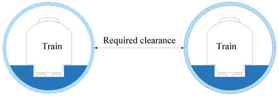
Figure 1.
Cross-section of the Circle shield tunnel.
To effectively improve the use of underground space, irregular cross-section shield tunnels [3], particularly the Double-O-Tube (DOT) shield tunnel, have been developed. The cross-section of the DOT shield tunnel consists of two overlapping single circles, as illustrated in Figure 2. This design allows for simultaneous bidirectional train traffic following a single excavation, effectively reducing the impacts of sequential construction and minimizing disturbances to surface structures, thereby saving time and costs [4].
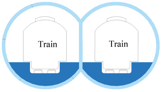
Figure 2.
Cross-section of the DOT shield tunnel.
Compared to two traditional circular tunnels, the DOT shield tunnel reduces the excavation area by 24% and decreases the total width by 14%, thus conserving valuable underground space resources and enhancing their effective utilization. The comparison between Figure 1 and Figure 2 reveals that the DOT shield method demonstrates superior construction capability in densely urbanized underground spaces compared to conventional single-circular tunneling. Notably, the traditional single-circular shield tunneling method inevitably causes twice the disturbance impacts on surrounding strata and underground structures during twin-tunnel construction, thereby significantly exacerbating operational risks to existing subsurface infrastructures. However, DOT shield tunneling technology currently faces three key challenges, including high construction control demands, pronounced shield machine deviation risks, and extremely precise segment assembly requirements. After further optimization of construction methods, the DOT shield technology will offer substantial application potential in densely populated urban areas, positioning it as a leading method for metro tunnel construction.
Over the past two decades, researchers have primarily focused on the ground surface displacement patterns induced by DOT shield tunneling [5,6,7], as well as the optimization of DOT shield tunneling technology [8,9]. However, little attention has been paid to investigating the longitudinal bending performance of the DOT shield tunnel. The longitudinal bending performances for all kinds of shield tunnels are of significance to assess the longitudinal responses of the shield tunnel and design the tunnel structure. In addition, the longitudinal bending stiffness is also an important parameter for evaluating the shield tunnel capacity to resist the additional loads or ground movements induced by adjacent construction activities. As a promising shield tunnel structure, the DOT shield tunnel will inevitably suffer additional loads or ground movements. Thus, it is urgent to investigate the longitudinal bending performances of DOT shield tunnels.
Similar to single-circular shield tunnels, DOT shield tunnels are also assembled by prefabricated segments connected with high-strength bolts during the tunneling process, forming an underground prefabricated composite slender cylindrical structure [10]. When subjected to nearby construction activities (e.g., sudden surface ground surcharge, new tunnel crossings, and adjacent deep excavation) and long-term train vibrations, such composite structures are prone to uneven longitudinal displacements. This can lead to issues such as leakage at the segment joints, damage and cracking of the segments, and bolt failures, all of which threaten train operational safety. Liu et al. [11] report that the Shanghai Metro Line 14 twin tunnels (single-circular shield tunnels) perpendicularly underpassed the existing DOT shield tunnel of Shanghai Metro Line 6 with a minimum vertical distance of 5.05 m in soft ground. The DOT shield tunnel experienced longitudinal uneven heave displacement and significant rotation of tunnel structure due to the undercrossing of Metro Line 14. This case indicates that to reasonably assess the responses of the DOT shield tunnel due to adjacent construction activities, the longitudinal bending performances of the DOT shield tunnel should be fully investigated.
Due to the rapid underground space development, similar adjacent construction activities will undoubtedly increase, making it increasingly important to assess the deformation and the structural safety of operational tunnels. In this context, the longitudinal bending stiffness is a crucial mechanical parameter for assessing the longitudinal responses of a single or DOT shield tunnel under external geotechnical activities. Therefore, investigating the longitudinal flexural performance of shield tunnels is of significant importance.
Shiba et al. [12] first proposed the longitudinal equivalent continuous model and derived an analytical solution for the LEBS of single-circular shield tunnels. Subsequently, numerous researchers have further refined his theory and proposed several analytical methods for determining the longitudinal bending stiffness of single-circular shield tunnels [13,14,15,16,17]. Li et al. [13] conducted a model test to explore the longitudinal bending behaviors of the circular shield tunnel and proposed a modified analytical solution to determine the LEBS. Wang et al. [14] proposed an enhanced analytical method to assess the nonlinear longitudinal equivalent bending stiffness of the shield tunnel by considering the coupling of bending moment and axial force. Huang et al. [15] proposed a novel analytical model to determine the LEBS, which considers the circumferential joint fiber and multiple forces (including bending and moment). Zhang et al. [16] treated the shield tunnel as a series of short beams connected with joint springs (i.e., rotation spring, shear spring, and torsional spring) and proposed an analytical solution to investigate the shearing–bending–torsional behaviors of the shield tunnel when subjected to above-tunneling and adjacent excavation. Ren et al. [17] conducted a model test to investigate the longitudinal response of shield tunnel linings by considering the axial forces and bending moment. They found that the LEBS increases exponentially due to the axial forces. Their works have been successfully applied to assess the longitudinal responses of single-circular shield tunnels when subjected to adjacent construction activities, as well as for safety assessments [18,19,20,21,22]. However, few analytical methods have been proposed to determine the longitudinal equivalent flexural stiffness of DOT shield tunnels, making it difficult to assess their longitudinal response and structural safety under external construction activities.
DOT shield tunnels are special irregular cross-section structures formed by the combination of two large arcs, resulting in notable differences in longitudinal bending performance compared to two independent single-circular shield tunnels. Therefore, it is inappropriate to simply analogize or replicate the bending stiffness values from single-circular shield tunnels. The unique structural characteristics of DOT shield tunnels must be fully considered to develop a longitudinal equivalent bending stiffness model that aligns with their cross-sectional features.
Taking into account the cross-sectional features of the DOT shield tunnel, an analytical solution for the longitudinal equivalent bending stiffness is proposed based on the longitudinal equivalent continuous model. According to the structural parameters of China’s first DOT shield tunnel, the effects of bolt number, segment thickness, segment width, and pillar height on the longitudinal bending stiffness are further analyzed. Ultimately, formulas related to the deformation and stress indices of the DOT shield tunnel structure are given, and the longitudinal safety of the DOT shield tunnel structure is analyzed.
2. Derivation of Longitudinal Equivalent Bending Stiffness for Double-O-Tube Shield Tunnels
Figure 3 illustrates the cross-section of the DOT shield tunnel. The tunnel cross-section can be roughly divided into three parts: the upper double arches, the waist, and the lower double arches, all with a thickness of t. In addition, r represents the distance from the center of the arc to the bolts, and R is the radius of the arcs. Therefore, 2R denotes the diameter of the arcs or the height of the tunnel. The angle dα corresponds to any differential element along the arc. The neutral axis position angle φ is defined as the angle between the line connecting the intersection of the neutral axis and the segment centerline with the center of the arc and the vertical line through the center. The distance x is the distance from the neutral axis to the center, x = rcosφ. Additionally, β denotes half of the central angle corresponding to the upper and lower arches, reflecting the height of the pillars, which can be referred to as the pillar height angle.
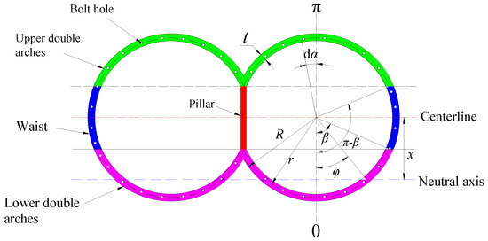
Figure 3.
Sectional view of DOT shield tunnel lining.
The distance ls is between the centerlines of two adjacent segment rings. Each half of the segmental rings is taken as the calculation unit. When a bending moment M is imposed on the segment, deformation and rotation occur, resulting in an angle of rotation θ, as illustrated in Figure 4.
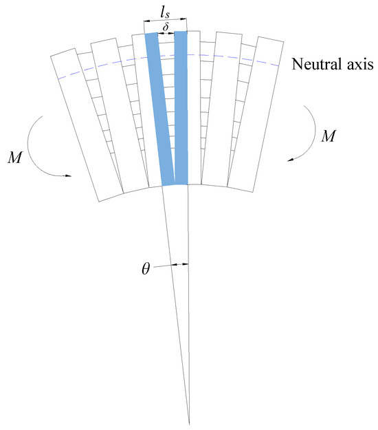
Figure 4.
Bending distortion of segment rings.
Some assumptions are made as follows:
- (1)
- The tunnel cross-section is assumed to remain a plane after deformation, with the deformation at any point on the cross-section being proportional to its distance from the neutral axis. This assumption aligns with Saint-Venant’s principle.
- (2)
- The distribution of bolts in the circumferential direction is treated as a continuous uniform distribution. When the length of the bolt is lb, the average linear stiffness kr of the bolts is given by [12]
- (3)
- Under the action of the bending moment, the ring’s cross-section is divided into a compression zone and a tension zone by the neutral axis. For the compression zone, the pressure is solely borne by the segment. As for the tension zone, the tensile stress is shared by both the bolts and the segment.
- (4)
- The tensile and compressive stresses on the bolts and segments are all below the elastic limit, resulting in elastic deformation. Both components are considered to be in a fully elastic state, without accounting for the influence of the segment joints.
- (5)
- The pillar in the DOT shield tunnel structure is not connected with adjacent rings and acts as a pure compressive member, contributing no resistance to the longitudinal bending performance. Therefore, the influence of the pillar on the longitudinal bending stiffness is neglected.
The DOT shield tunnel is an assembled composite structure. Similar to the single-circular shield tunnel, when subjected to a bending moment, the neutral axis does not coincide with the centroidal axis. Due to the unique sectional geometry of this shield tunnel, the neutral axis may lie within the waist arc of the cross-section (β < φ ≤ π−β) or within the lower double arches of the section (0 ≤ φ ≤ β). Therefore, when deriving its longitudinal equivalent bending stiffness, it is essential to consider these sectional characteristics and discuss the two situations separately.
2.1. Neutral Axis Located Within the Waist of the Ring Section (β < φ ≤ π−β)
When the neutral axis is located within the waist arc of the ring section, the longitudinal stress deformation is shown in Figure 5. From Figure 5, due to the bending moment M, the deformation compatibility can be expressed as follows [16]:
where εc and εt represent the maximum compressive strain and tensile strain at the segment joint, respectively. δ represents the joint opening at the joint.

Figure 5.
Longitudinal stress and deformation when the neutral axis is located at the waist of the ring section.
According to the force equilibrium condition, the resultant forces in the compressive zone below the neutral axis and the tensile zone above the neutral axis are equal. The force balance equations for the compressive and tensile zones are as follows:
where Es represents the elastic modulus of the concrete segments.
According to the moment equilibrium condition, the resultant moment from the compressive stress and the tensile stress about the neutral axis should be equal to the imposed bending moment M. Thus, the moment balance equation can be expressed as follows:
By combining Equations (2)–(4), the expression about the angle of the neutral axis position angle φ can be given as
where
By further combining Equations (2)–(5), the rotation angle θ and the angle of the neutral axis position angle φ satisfy the following relationship:
where
Assuming J1 = t(A3−A4), J2 = t(A5−A6), Equation (7) can be simplified as
According to the equivalent continuous model, the rotation angle θ is given by [14]
By combining Equations (8) and (9), the longitudinal equivalent bending stiffness (EI)eq when the neutral axis is located within the waist of the DOT shield tunnel ring section (0 ≤ x ≤ rcosβ) can be further obtained as
According to Equation (10), the longitudinal equivalent bending stiffness (EI)eq is only dependent on the geometric shape of the ring section and material properties of the lining, and is independent of the bending moment M.
2.2. Neutral Axis Located Within the Lower Arch of the Ring Section (0 ≤ φ ≤ β)
When the neutral axis is located within the lower arch of the ring section (0 ≤ φ ≤ β), the longitudinal stress deformation induced by imposed moment M is shown in Figure 6. The variation in the position of the neutral axis leads to the change in the compressive and tensile zones. However, the deformation compatibility conditions for these zones remain the same as in Equations (2) and (3). Based on the force equilibrium condition, the force balance equations for the tensile zone above the neutral axis and the compressive zone below it can be expressed as
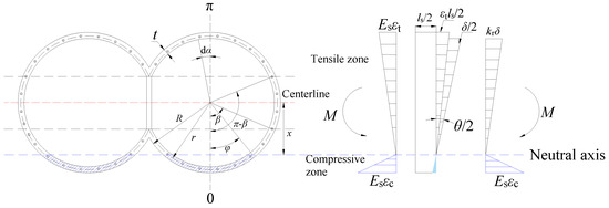
Figure 6.
Longitudinal stress and deformation when the neutral axis is located at the double invert of the ring section.
The resultant moment from the compressive and tensile zones about the neutral axis is equal to the longitudinal bending moment. Therefore, the moment balance equation can be expressed as
Similarly, by combining Equations (2), (3), (11a), and (11b), the neutral axis position angle φ satisfies the following equation:
where , .
By combining Equations (2), (3), (11), and (12), the longitudinal equivalent bending stiffness (EI)eq when the neutral axis is located within the lower arch of the ring section (0 ≤ φ ≤ β) can be obtained as follows:
where
Similarly, according to Equation (14), when the neutral axis is located within the lower arch of the ring section (0 ≤ φ ≤ β), the equivalent bending stiffness is also only related to the sectional parameters and is independent of the applied bending moment M.
The longitudinal equivalent stiffness efficiency (LESE), ηL, is also a useful parameter for evaluating the bending performances of the shield tunnel. It is defined as the ratio of the longitudinal equivalent bending stiffness of the shield tunnel to the homogeneous continuous tunnel. The expression is given by [10]
where Ic is the moment of inertia for the shield tunnel.
For the DOT shield tunnel, the moment of inertia Ic is given by
3. Case Analysis
In 2002, the section between Huangxing Green Space Station and Kairu Road Station of Shanghai Metro Line M8 was constructed using the DOT shield tunneling method, marking it as the first DOT metro tunnel section in China. The tunnel cross-section has a width of 10.9 m, a segment diameter of 2R = 6.3 m, a distance from the center to the bolt r of 3 m, a pillar height h of 3.5 m, an angle of pillar height β of 54.3°, a ring width ls of 1.2 m, and a segment thickness t of 0.3 m. Relevant parameters are summarized in Table 1.

Table 1.
Design parameters for DOT shield tunnel lining.
Based on the parameters of Shanghai Metro Line M8 DOT shield tunnel, the effects of various factors on the longitudinal performances of the DOT shield tunnel study are analyzed, including the number of bolts n, the segment thickness t, the segment width ls, and the pillar height h. Table 2 presents the mechanical parameters of the bolts. It should be noted that all parametric analyses discussed in this study are conducted based on the baseline conditions specified in Table 1 and Table 2. When examining the variation in any particular parameter, all other parameters were maintained constant at their reference values.

Table 2.
Mechanical parameters of bolts.
3.1. Effects of the Number of Bolts on the LEBSE ηL
Figure 7 illustrates the variation in the LESBE ηL and the neutral axis position angle φ with respect to the number of bolts n. A roughly linear relationship between the number of bolts n and the LESBE ηL is observed. With an increase in the number of bolts n, the value of ηL significantly increases. Concurrently, the neutral axis position angle φ also increases with the number of bolts n. The increase in the neutral axis position angle φ indicates that the neutral axis shifts upward, which enlarges the compression zone. Correspondingly, the tension zone is reduced. It means that increasing the bolt number can reduce the water leakage at joint openings and damage or cracking of the segments. As the number of bolts n increases, the average linear stiffness kr of the circumferential joints improves, thereby enhancing the ability to resist joint opening and ultimately increasing the tunnel’s longitudinal equivalent stiffness. It is important to note that an increase in the number of bolts will complicate the assembly construction of the segments. Therefore, the number of bolts used to connect the segments should be reasonably determined in consideration of the potential loading conditions of the tunnel.
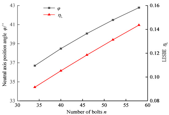
Figure 7.
Effects of the number of bolts, n, on the LEBSE, ηL, and the neutral axis position angle, φ.
3.2. Effects of Segment Thickness t on the LESBE, ηL
Figure 8 illustrates the impacts of segment thickness t on the LESBE, ηL, and the neutral axis position angle φ. With an increase in segment thickness t, the neutral axis position angle φ decreases linearly. It will lead to downward movement of the neutral axis. Finally, it results in a reduction in the compression zone and an increase in the tension zone, which is detrimental to the waterproof sealing at tunnel segment joints. Additionally, the values of LESBE ηL also decrease with increasing segment thickness t, exhibiting a roughly linear relationship. However, the reduction in the LESBE does not mean the absolute value of the longitudinal bending stiffness is also reduced. Figure 9 presents the variations in the longitudinal equivalent bending stiffness value (EI)eq and the bending stiffness of a homogeneous continuous tunnel EI with respect to the segment thickness t. Comparing Figure 8 and Figure 9, it is evident that as the segment thickness t increases, the values of longitudinal bending stiffness value (EI)eq also rise, as well as the bending stiffness of a homogeneous continuous tunnel EI. The bending stiffness for the homogeneous continuous tunnel increases with a greater magnitude by thickening the segment thickness, when compared with the DOT shield tunnel. Eventually, it leads to a relative reduction in ηL. It shows a roughly linear relationship between the longitudinal equivalent bending stiffness value (EI)eq and segment thickness t, with an average increase of approximately 6 × 10⁶ kN·m/rad for every 0.05 m increase in thickness. Thus, increasing segment thickness t is beneficial for enhancing the longitudinal bending stiffness.
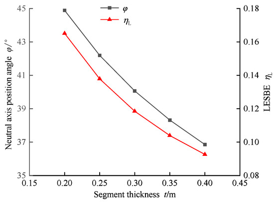
Figure 8.
Effects of the thickness of lining, t, on the LESBE, ηL, and the neutral axis position angle, φ.
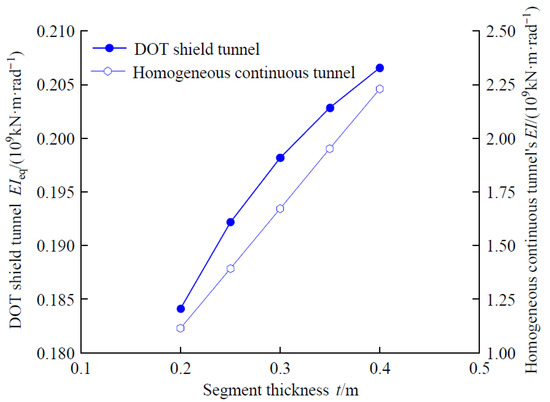
Figure 9.
Effects of the thickness of segmental lining, t, on the longitudinal equivalent bending stiffness for the DOT shield tunnel, (EI)eq, and the bending stiffness for the homogeneous continuous tunnel, EI.
3.3. Effects of Segment Width ls on the LESBE ηL
Figure 10 shows the impact of segment width ls on the LEBSE ηL and the neutral axis position angle φ. With an increase in segment width ls, both the neutral axis position angle φ and the LEBSE ηL exhibit a roughly linear increase. Accordingly, the neutral axis moves upward if the segment width ls is widened. For every 0.2 m increase in segment width, the effective efficiency of longitudinal bending stiffness ηL improves by approximately 1.75%. This indicates that increasing segment width ls can significantly enhance the tunnel’s capacity to resist deformation. Furthermore, when the total length of the tunnel remains unchanged, increasing segment width ls can reduce the number of joints between segments, thereby minimizing the risk of water leakage and bolt fracture between the segments. Therefore, in the structural design of segments, while ensuring the adaptability and feasibility of manufacturing, transportation, and assembly, it is advisable to consider increasing segment width within a reasonable range.
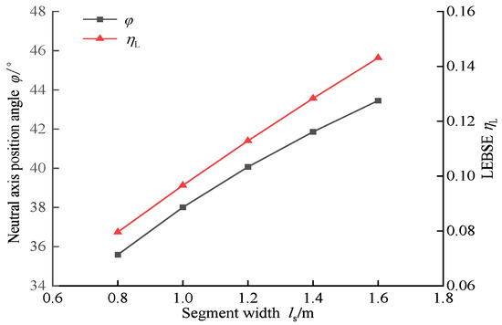
Figure 10.
Effects of the segment width, ls, on LEBSE, ηL, and the neutral axis position angle, φ.
3.4. Effects of the Pillar Height h on the LEBSE ηL
The pillar height angle β and the distance from the center to the bolt r are key parameters to determine the cross-section of the DOT shield tunnel lining. As shown in Figure 3, the relationship between the pillar height h, the pillar height angle β, and the distance from the center to the bolt r can be expressed as
h = 2rcosβ
According to the equation, it can be seen that when the distance from the center to the bolt r is fixed, the pillar height angle β reflects the pillar height h. It indirectly indicates the degree of overlap between the two arcs, thus defining the shape of the DOT tunnel cross-section. In the following analysis, the pillar height angle β will be used as the main parameter to examine the effect of pillar height h on the LEBSE ηL. Since an increase in the pillar height angle β leads to an increase in the perimeter of the ring section, it is assumed that the average linear stiffness kr at the segment interface remains constant.
Figure 11 presents the variations in the LEBSE ηL and the neutral axis position angle φ with the pillar height angle β. When the pillar height angle β increases, the neutral axis position angle φ gradually rises, indicating that the neutral axis will shift upward if the pillar height decreases. In contrast, the value of ηL exhibits a pattern of rapid decrease followed by a slow increase with increasing β. Specifically, when β increases from 10° to 45°, ηL decreases sharply from 0.129 to 0.118, reaching its minimum value at β = 45°. Subsequently, as β continues to increase, ηL slowly rises, reaching a value of 0.12 at β = 80°.
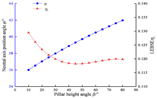
Figure 11.
Effects of the pillar height angle, β, on the LEBSE, ηL, and the neutral axis position angle, φ.
Figure 12 shows the variation in the longitudinal equivalent bending stiffness (EI)eq with the pillar height angle β. As the pillar height angle β increases, the longitudinal equivalent bending stiffness (EI)eq generally shows an increasing trend. Specifically, when β varies from 10° to 60°, (EI)eq increases sharply. By further increasing the value of β, a reduced increase in (EI)eq is observed.
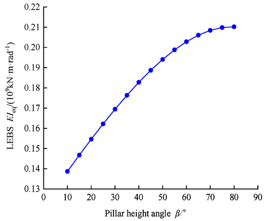
Figure 12.
Effects of the pillar height angle, β, on LEBS, (EI)eq.
Combining Figure 11 and Figure 12, it reveals that as the pillar height angle β rises, the LEBES ηL shows an overall decreasing trend, while (EI)eq increases. This phenomenon can be attributed to the fact that as β increases, the shape of the DOT shield tunnel cross-section allows the segment area to engage more effectively with the forces, leading to an increase in the moment of inertia Ic. Consequently, the bending stiffness of the continuous tunnel increases, resulting in the observed trend of ηL initially decreasing and then increasing. Thus, the pillar height angle β is a key parameter influencing the shape of the tunnel cross-section, and changes in β will alter the cross-section. Subsequently, it affects the value of ηL.
4. Deformation and Stress Indicators for DOT Shield Tunnels
Similar to conventional single-circular shield tunnels, Double-O-Tube shield tunnels experience adverse effects due to long-term operational train loads and adjacent construction activities (such as ground surface surcharge, new tunnel crossings, and nearby deep excavation). These effects can lead to longitudinal uneven displacement, joint opening, and even issues like bolt loosening and lining damage. To ensure the safety of operational shield tunnels, according to the Technical Specification for Structural Safety Protection of Urban Rail Transit (TCPSURT) [23], the warning and control thresholds for the joint opening of shield segments should be less than 1 mm and 2 mm, respectively. The radius of curvature of the tunnel should be greater than 15,000 m. Furthermore, the maximum tensile stress on the bolts must be less than their yield strength [σb] to prevent permanent plastic deformation. The tensile stress σt and compressive stress σc on the segments should remain within the yield tensile stress [σt] and compressive stress [σc] limits to avoid cracking and crushing of the lining.
Based on the above-mentioned expressions for the longitudinal equivalent bending stiffness of DOT shield tunnels, the formulas of the deformation and stress indicators of the tunnel can be further established, including the radius of curvature ρ, concrete tensile stress σt, concrete compressive stress σc, joint opening δ, and bolt tensile stress σb.
Based on the structural design parameters of the DOT shield tunnel for Shanghai Metro Line M8, the neutral axis position angle φ is determined to be 40°. Therefore, the neutral axis is located within the lower arch section (0 ≤ φ ≤ β). Consequently, we use the formula for the neutral axis positioned in the lower arch section to calculate the aforementioned indicators. The radius of curvature is defined as the ratio of bending stiffness to the bending moment M. By substituting Equation (14), the radius of curvature ρ of the DOT shield tunnel can be given as follows:
By simultaneously solving Equations (2), (9), and (14), the maximum compressive strain of the concrete εc can be obtained:
By substituting Equation (19) into Equations (4a) and (4b), the maximum tensile strain εt and the joint opening δ can be obtained, respectively:
Moreover, according to Equation (21), the maximum tensile stress of the bolt σb can be further obtained:
Based on Equations (18)–(22), the variations in deformation and stress indicators corresponding to different curvature radii of the DOT shield tunnel can be calculated. Figure 13 illustrates the variations in the tensile and compressive stresses of the concrete segments as the curvature radius varies. Figure 14 shows the relationship between the tensile stress of the bolts and the joint opening with respect to the curvature radius. The bolts with a yield strength of [σb] = 640 MPa were selected to connect the segmental rings in the M8 Line project. The tensile strength [σt] and compressive strength [σc] for the M8 Line’s concrete precast segments are 2.64 MPa and 32.4 MPa, respectively. The maximum tensile and compressive stresses of the concrete segment increase by increasing the curvature radius ρ. As shown in Figure 13 and Figure 14, it can be observed that when the tunnel curvature radius ρ is equal to 15,000 m, the maximum tensile and compressive stresses experienced by the concrete segments are both below their corresponding standard strength values. Meanwhile, the maximum tensile stress σb on the bolts is 234 MPa, which is significantly less than the yield limit. The maximum joint opening δ is only 0.4 mm, below the warning threshold (e.g., 1 mm). Thus, it can be concluded that the specified control value for the curvature radius ρ of 15,000 m provides a considerable safety margin, indicating a favorable stress state for the tunnel structure.
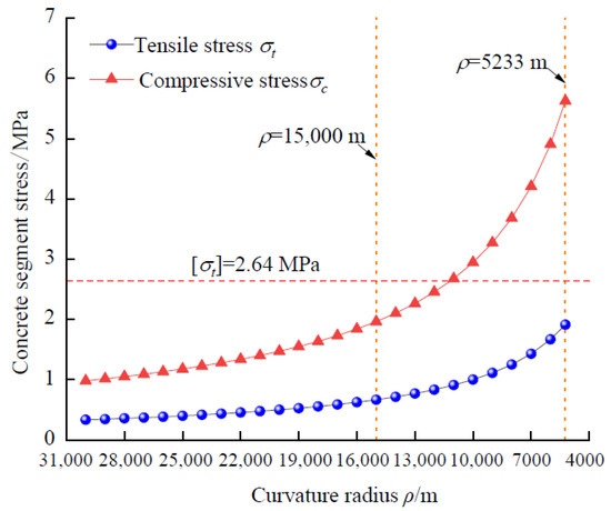
Figure 13.
Variation in tensile and compressive stress of concrete segmental lining with the radius of curvature, ρ.
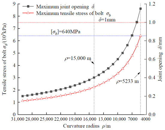
Figure 14.
Variation in the maximum joint opening and the tensile stress of bolts with the radius of curvature, ρ.
As the tunnel curvature radius ρ further decreases to 5233 m, the maximum tensile stress on the bolts reaches their yield limit [σb], while the joint opening is 1.15 mm, exceeding the warning threshold. The maximum tensile and compressive stresses in the concrete segments remain below their respective standard strength values. It is evident that when the curvature radius is less than 5233 m, the tunnel is likely to experience plastic deformation of the bolts and localized waterproofing failure first. Therefore, it is crucial to strictly control the longitudinal uneven displacement of the shield tunnel to prevent structural damage due to excessively small curvature radii.
5. Conclusions
An analytical solution for the longitudinal equivalent bending stiffness (LEBS) of DOT shield tunnels has been derived, considering the irregular cross-section structure and two scenarios for the neutral axis location (waist and lower arch). Formulas for calculating deformation and stress indices have also been established. The main conclusions are as follows:
- (1)
- The Double-O-Tube shield tunnel has a non-standard cross-section, and the neutral axis may be located at either the mid-section or the lower arch. These two situations should be considered separately when establishing formulas for its longitudinal bending stiffness.
- (2)
- The number of bolts n exhibits a roughly linear relationship with the efficiency of longitudinal equivalent bending stiffness ηL. As the number of bolts n increases, the neutral axis rises, leading to an increase in ηL.
- (3)
- As the thickness of the segments t increases, the neutral axis descends, resulting in a decrease in the efficiency ηL. However, the value of the longitudinal equivalent bending stiffness increases with the thickness t. Increasing the segment width ls causes the neutral axis to rise, which in turn increases the value of ηL.
- (4)
- An increase in the pillar height angle causes the neutral axis to shift upward, resulting in an increase in LEBS. When the pillar height angle is increased from 10° to 45°, the LEBSE decreases rapidly initially, followed by a gradual increase with further elevation in the angle.
- (5)
- Taking the Line M8 tunnel as an example, it was found that when the curvature radius is greater than or equal to 15,000 m, the tunnel structure is in a safe state with a significant safety reserve. However, when the curvature radius decreases to 5233 m, the maximum tensile stress on the bolts reaches their yield limit, and the joint opening exceeds the warning threshold.
- (6)
- The analytical solution is based on the assumption that the bolts and segmental lining remain in the elastic state when subjected to the bending moment. If the bending moment is sufficiently large, it will cause the bolts and segmental linings to enter a plastic state. In this case, the longitudinal bending performance of the DOT shield tunnel should be evaluated under plastic conditions.
Author Contributions
S.W.: Conceptualization, Methodology, Investigation, Formal Analysis, Writing—Original Draft. L.P.: Data Curation. Y.Z.: Conceptualization, Methodology, Formal Analysis. R.L.: Resources, Supervision, Writing—Original Draft. All authors have read and agreed to the published version of the manuscript.
Funding
This research received no external funding.
Data Availability Statement
Data are contained within the article.
Conflicts of Interest
Authors Senyong Wang and Lehua Peng were employed by the company The South of Zhejiang Comprehensive Engineering Survey and Mapping Institute Co., Ltd. The remaining authors declare that the research was conducted in the absence of any commercial or financial relationships that could be construed as a potential conflict of interest.
References
- Sha, F.; Wang, Q.; Wang, N.; Liu, F.; Ni, L. Performance of underwater shield synchronous double-liquid plastic grout with high W/C and volume ratio. Constr. Build. Mater. 2025, 465, 140172. [Google Scholar] [CrossRef]
- Lee, J.; Yoo, H.; Ban, H.; Park, W. Estimation of rock load of multi-arch tunnel with cracks using stress variable method. Appl. Sci. 2020, 10, 3285. [Google Scholar] [CrossRef]
- Hu, D.; Liu, J.; Li, Y.; Tan, Z. Prediction method of ground settlement for rectangular tunnel construction. Tunn. Undergr. Space Technol. 2025, 164, 106814. [Google Scholar] [CrossRef]
- Chow, B. Double-O-tube shield tunneling technology in the Shanghai Rail Transit Project. Tunn. Undergr. Space Technol. 2006, 21, 594–601. [Google Scholar] [CrossRef]
- Ye, G.; Tadashi, H.; Shen, S.; Zhu, H.; Bai, T. Lessons learnt from unusual ground settlement during Double-O-Tube tunnelling in soft ground. Tunn. Undergr. Space Technol. 2015, 49, 79–91. [Google Scholar] [CrossRef]
- Chen, S.; Lee, S.; Wei, Y. Numerical analysis of ground surface settlement induced by double-O tube shield tunneling. J. Perform. Constr. Facil. 2016, 30, 04016012. [Google Scholar] [CrossRef]
- Gui, M.; Chen, S. Estimation of transverse ground surface settlement induced by DOT shield tunneling. Tunn. Undergr. Space Technol. 2013, 33, 119–130. [Google Scholar] [CrossRef]
- Hu, X.; Zhang, Z.; Li, T. An analytical method for internal forces in DOT shield-driven tunnel. Tunn. Undergr. Space Technol. 2009, 24, 675–688. [Google Scholar] [CrossRef]
- Shen, S.; Horpibulsuk, S.; Liao, S.; Peng, F. Analysis of the behavior of DOT tunnel lining caused by rolling correction operation. Tunn. Undergr. Space Technol. 2009, 24, 84–90. [Google Scholar] [CrossRef]
- Wu, H.; Shen, S.; Liao, S.; Yin, Z. Longitudinal structural modelling of shield tunnels considering shearing dislocation between segmental rings. Tunn. Undergr. Space Technol. 2015, 50, 317–323. [Google Scholar] [CrossRef]
- Liu, Y.; Liao, S.; Chen, L.; Liu, M. Structural responses of DOT tunnel induced by shield under-crossing in close proximity in soft ground. Part I: Field measurement. Tunn. Undergr. Space Technol. 2022, 128, 104623. [Google Scholar] [CrossRef]
- Shiba, Y.; Kawashima, K.; Obinata, N.; Kano, T. Evaluation procedure for seismic stress developed in shield tunnels based on seismic deformation method. Proc. Jpn. Soc. Civ. Eng. 1989, 1989, 385–394. [Google Scholar] [CrossRef]
- Li, X.; Zhou, X.; Hong, B.; Zhu, H. Experimental and analytical study on longitudinal bending behavior of shield tunnel subjected to longitudinal axial forces. Tunn. Undergr. Space Technol. 2019, 86, 128–137. [Google Scholar] [CrossRef]
- Wang, Z.; Shi, C.; Gong, C.; Lei, M.; Liu, J.; Cao, C. An enhanced analytical model for predicting the nonlinear longitudinal equivalent bending stiffness of shield tunnels incorporating combined N-M actions. Tunn. Undergr. Space Technol. 2022, 126, 104567. [Google Scholar] [CrossRef]
- Huang, L.; Huang, X.; Liang, Y.; Chang, Y. A novel longitudinal bending model of shield tunnel based on discretization of fiber section under the coupling of multiple factors. Tunn. Undergr. Space Technol. 2024, 154, 106063. [Google Scholar] [CrossRef]
- Zhang, Z.; Zheng, G.; Cheng, X.; Liang, R.; Li, C.; Zhong, Z.; Zhao, J. Analytical approach for longitudinal deformation of shield tunnels considering bending-shear-torsional effects of circumferential joints. Tunn. Undergr. Space Technol. 2024, 152, 105946. [Google Scholar] [CrossRef]
- Ren, L.; Yang, Z.; Zheng, J.; Chen, S.; Guan, Z. Experimental and numerical studies on the longitudinal equivalent bending stiffness of shield tunnel by considering axial force. Structures 2025, 75, 108776. [Google Scholar] [CrossRef]
- Liu, J.; Shi, C.; Lei, M.; Cao, C.; Lin, Y. Improved analytical method for evaluating the responses of a shield tunnel to adjacent excavations and its application. Tunn. Undergr. Space Technol. 2020, 98, 103339. [Google Scholar] [CrossRef]
- Liang, R.; Zhang, Z.; Wu, J.; Li, Z.; Cao, S.; Wu, W. Probabilistic assessment of existing shield tunnel longitudinal responses to tunneling. Int. J. Numer. Anal. Methods Geomech. 2024, 48, 2493–2520. [Google Scholar] [CrossRef]
- Liang, R.; Zhang, Z.; Li, Z.; Cao, S.; El Naggar, M.H.; Xiao, M.; Wu, W. Simplified method for predicting the shield tunnel longitudinal responses to over-crossing tunneling considering circumferential joint effect. Int. J. Geomech. 2024, 24, 04024140. [Google Scholar] [CrossRef]
- Quan, Y.; Tan, X.; Hu, Z.; Huang, M. Measurement and analysis of deformation of underlying tunnel induced by foundation pit excavation. Adv. Civ. Eng. 2023, 1, 8897139. [Google Scholar] [CrossRef]
- Li, H.; Li, X.; Yang, Y.; Liu, H. Analytical solution for the longitudinal response of cross-fault shield tunnel considering plastic deformation of circumferential joints. J. Cent. South Univ. 2023, 30, 1675–1694. [Google Scholar] [CrossRef]
- CJJ/T202-2013; Technical Code for Protection Structures of Urban Rail Transit (TCPSURT). China Architecture & Building Pres: Beijing, China, 2013. (In Chinese)
Disclaimer/Publisher’s Note: The statements, opinions and data contained in all publications are solely those of the individual author(s) and contributor(s) and not of MDPI and/or the editor(s). MDPI and/or the editor(s) disclaim responsibility for any injury to people or property resulting from any ideas, methods, instructions or products referred to in the content. |
© 2025 by the authors. Licensee MDPI, Basel, Switzerland. This article is an open access article distributed under the terms and conditions of the Creative Commons Attribution (CC BY) license (https://creativecommons.org/licenses/by/4.0/).