
Flexural Strength of Cold-Formed Steel Unstiffened and Edge-Stiffened Hexagonal Perforated Channel Sections

 ,
,  and
and
Abstract
1. Introduction
2. Overview of the Experimental Study Conducted by Chen et al. [1]
3. FE Analysis
3.1. Overview
3.2. Constitutive Material Behaviour
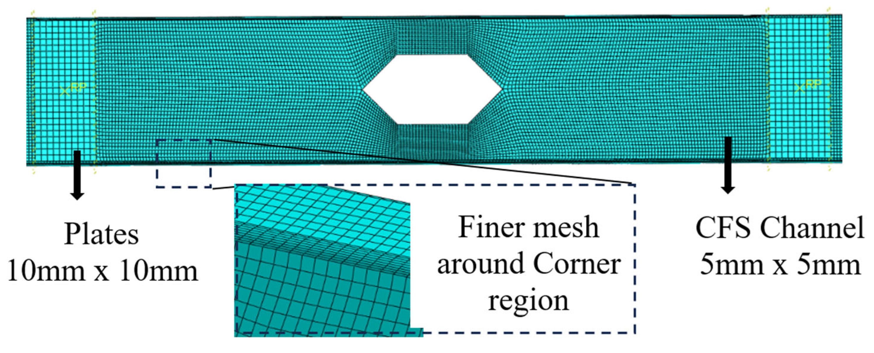
3.3. Finite Element Meshing
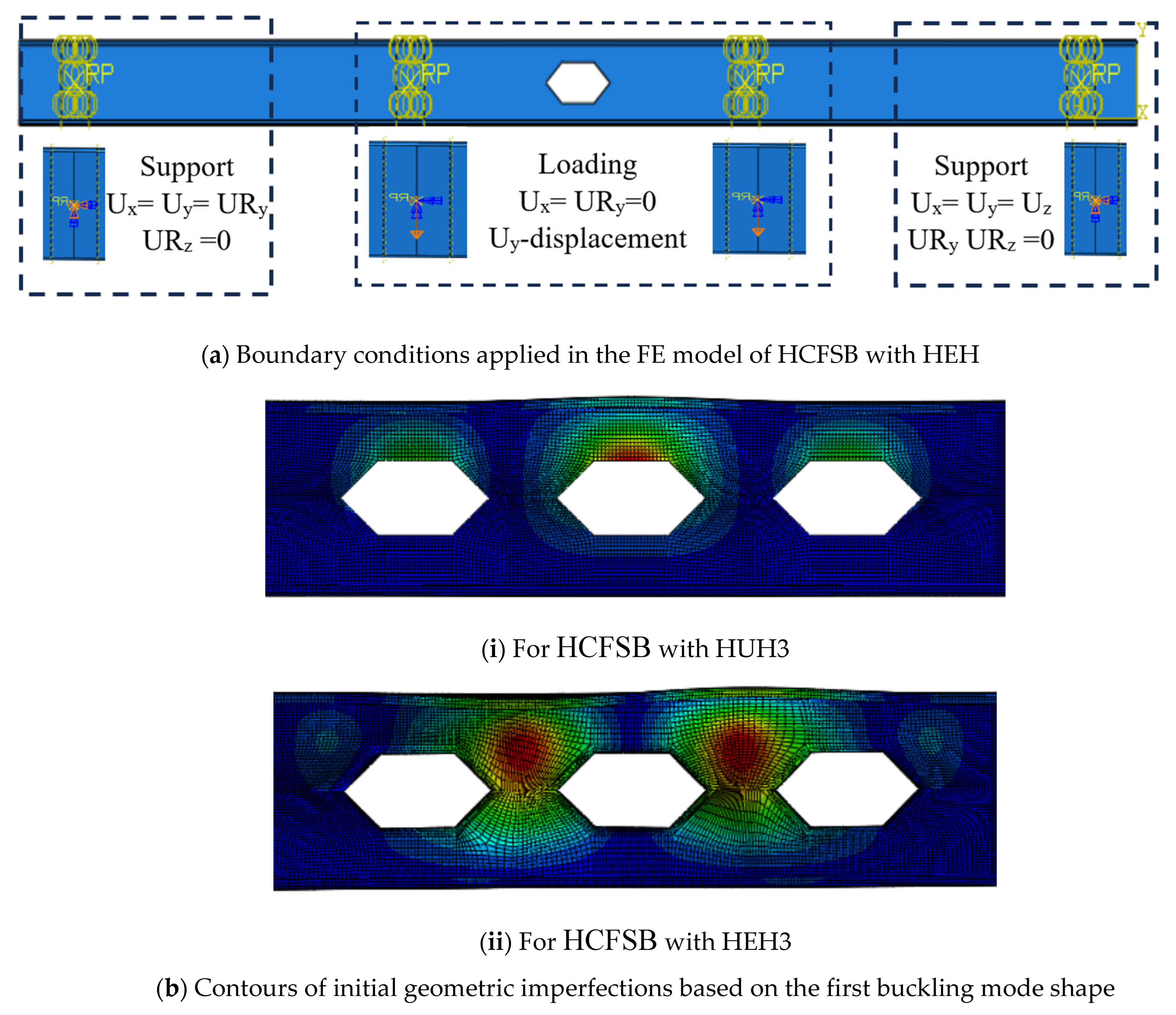
3.4. Application of Loading and Boundary Representation
3.5. Geometrical Imperfections
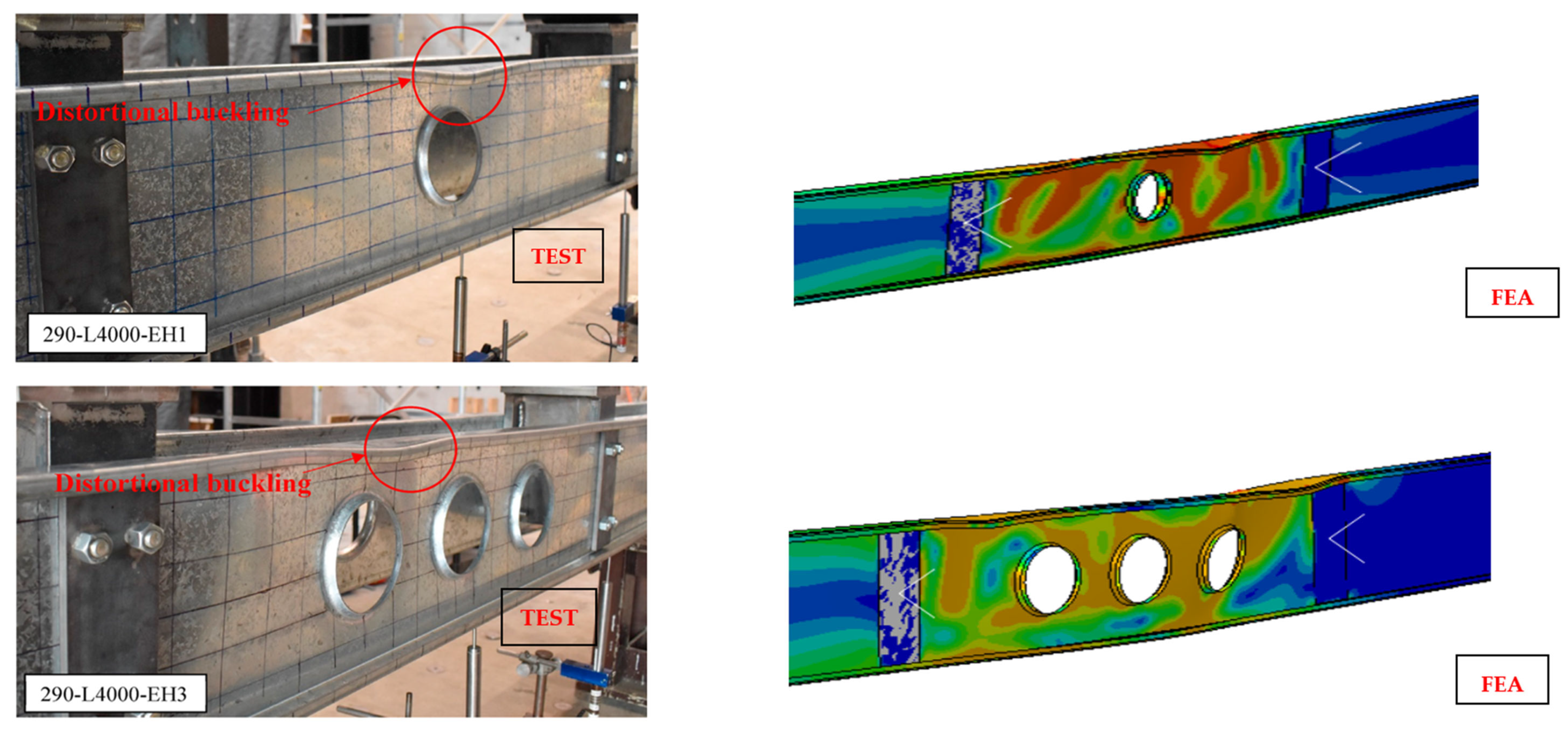
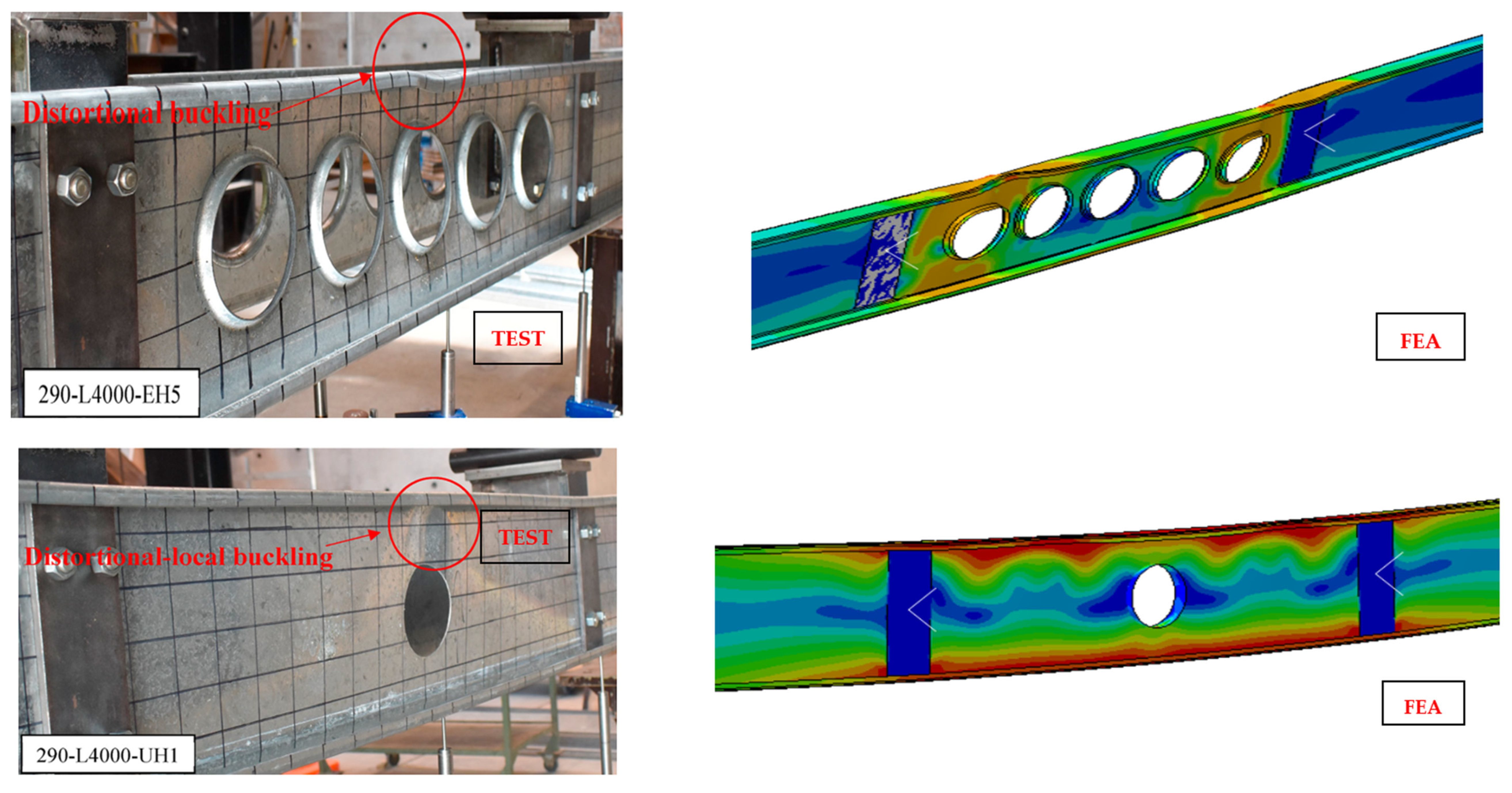
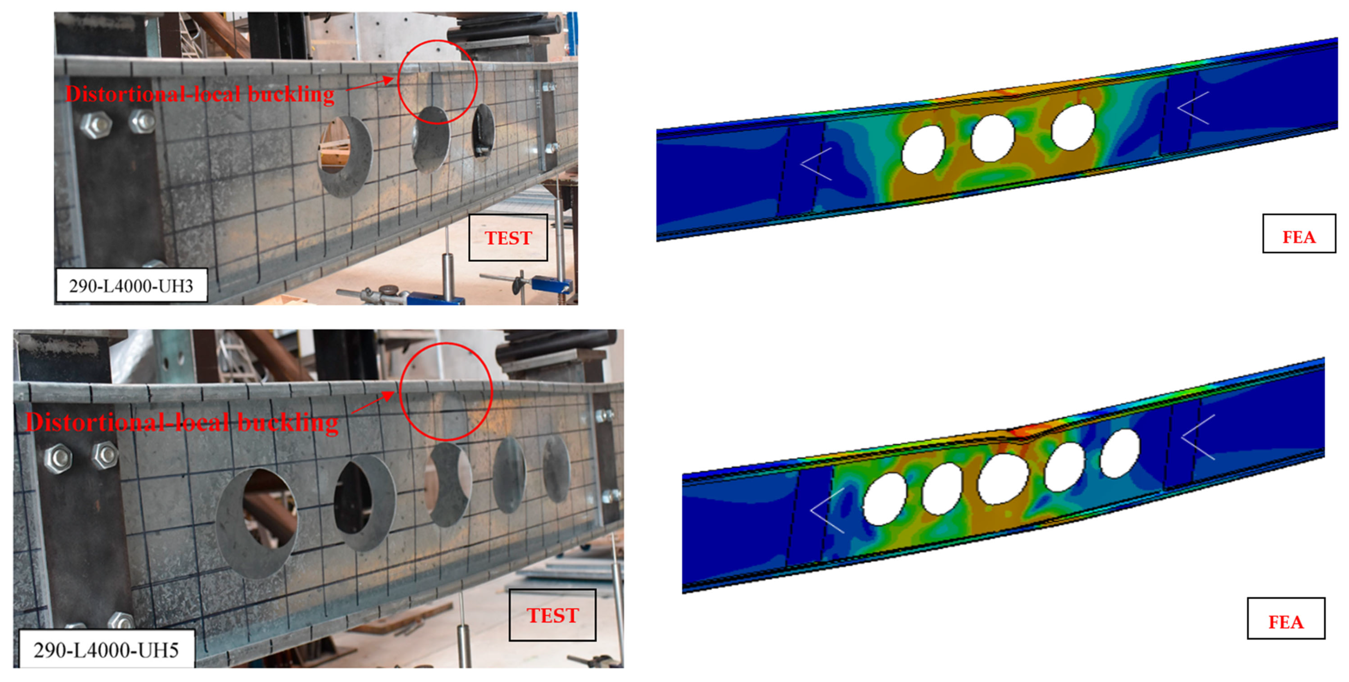
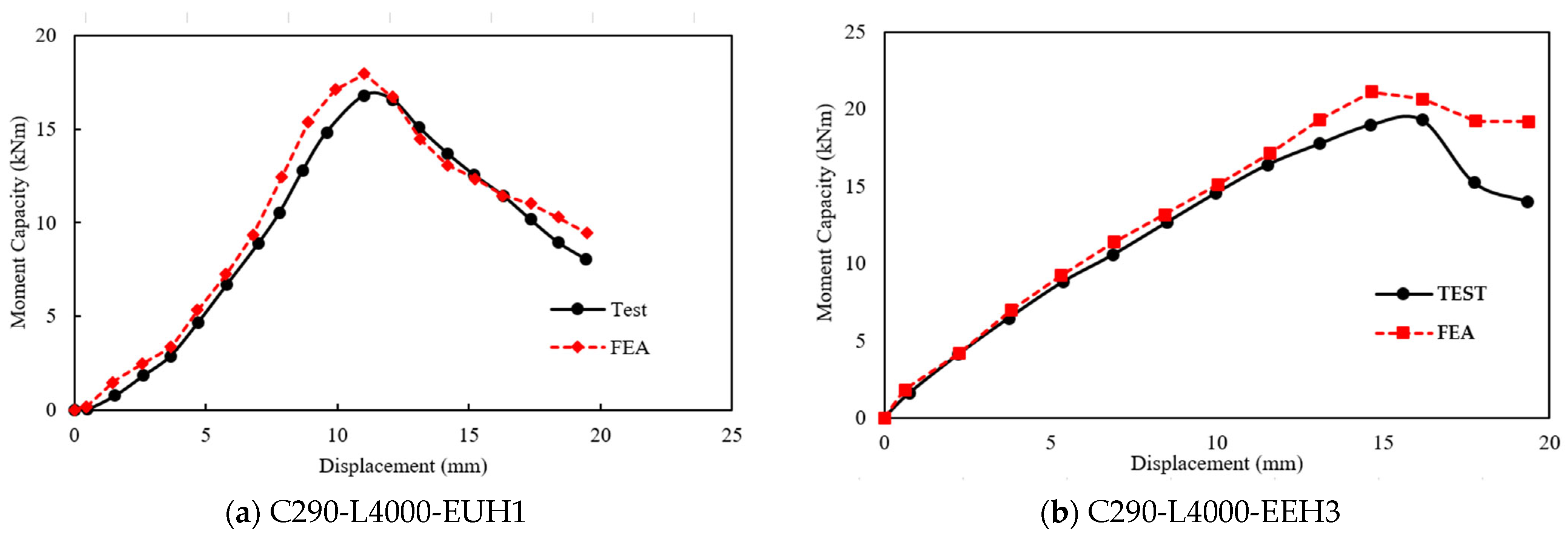
3.6. Validation
4. Parametric Study
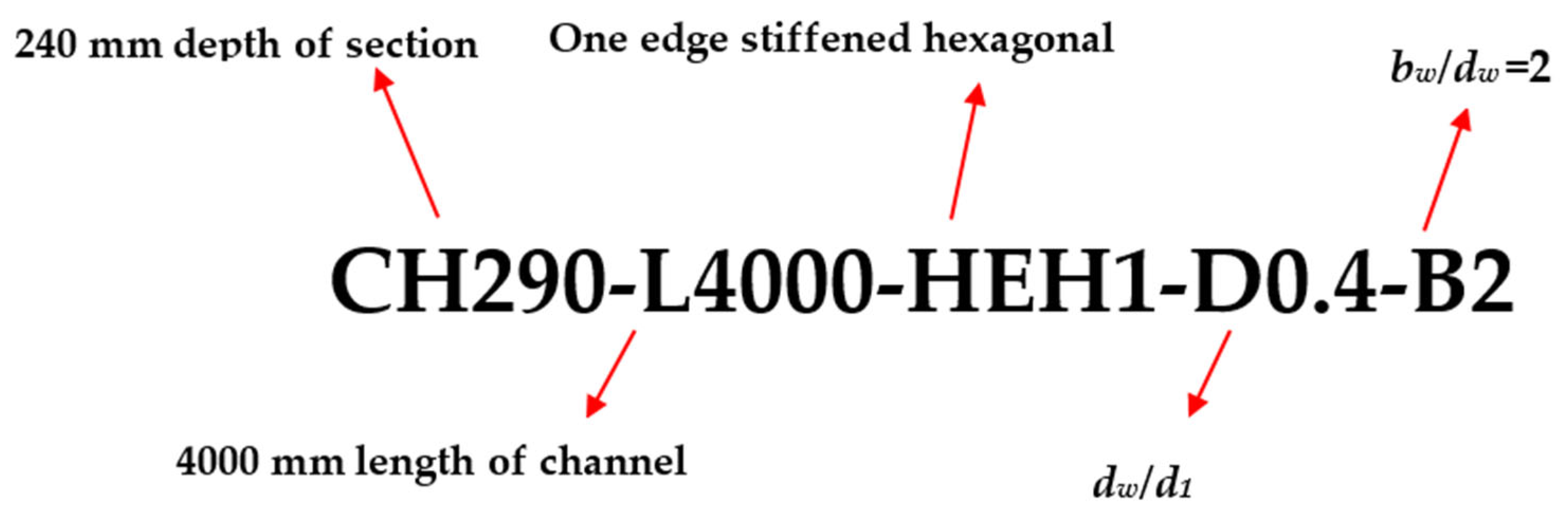
4.1. Overview and Specimen Coding
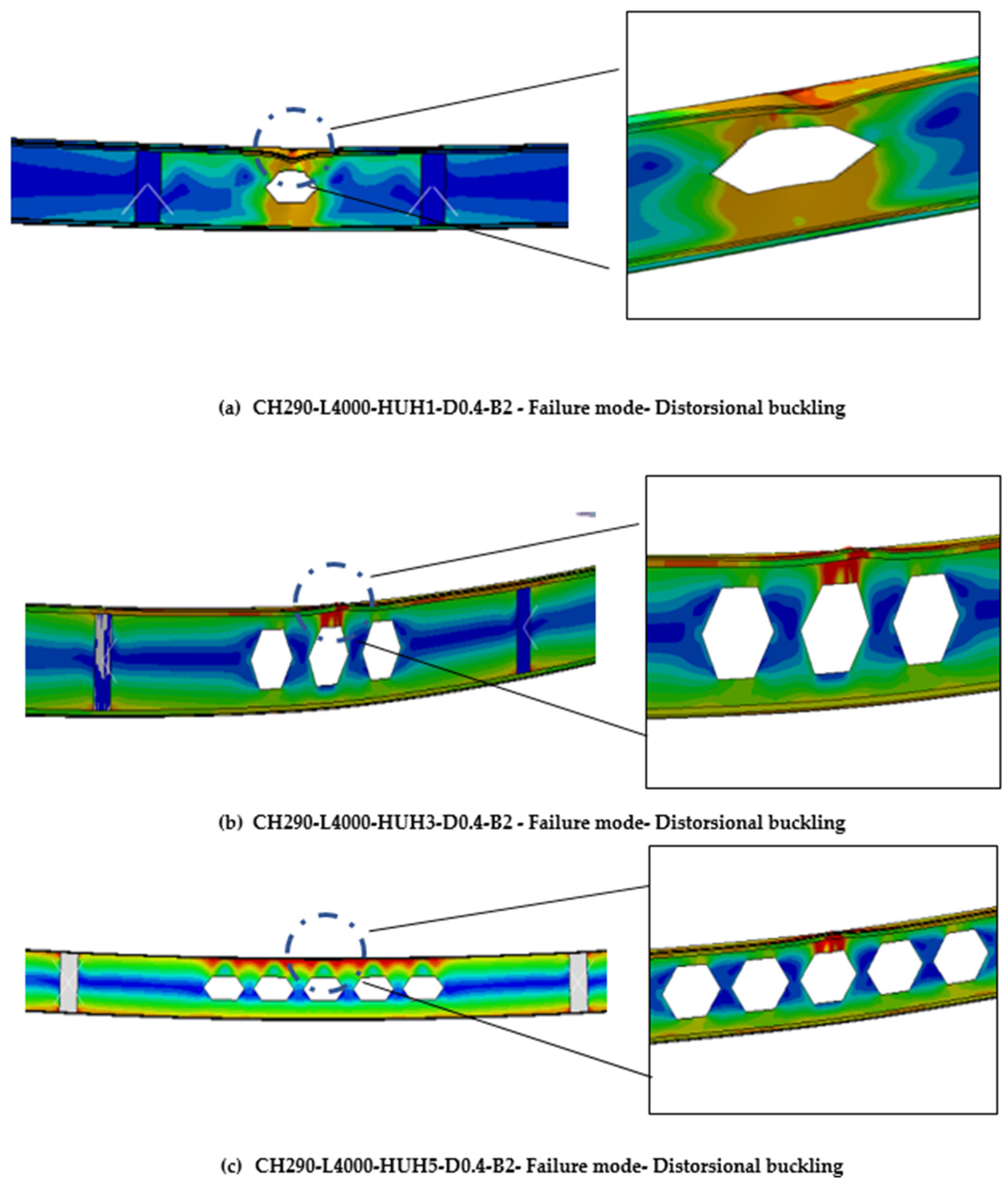
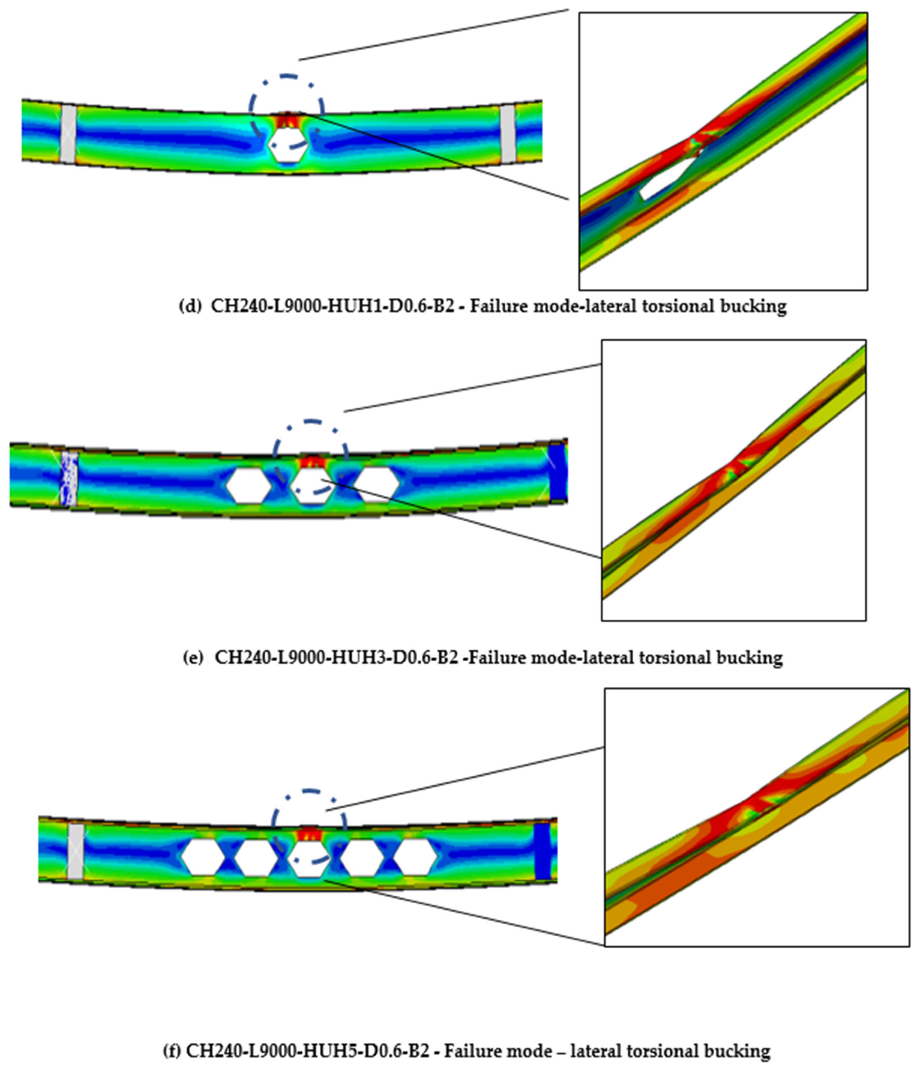
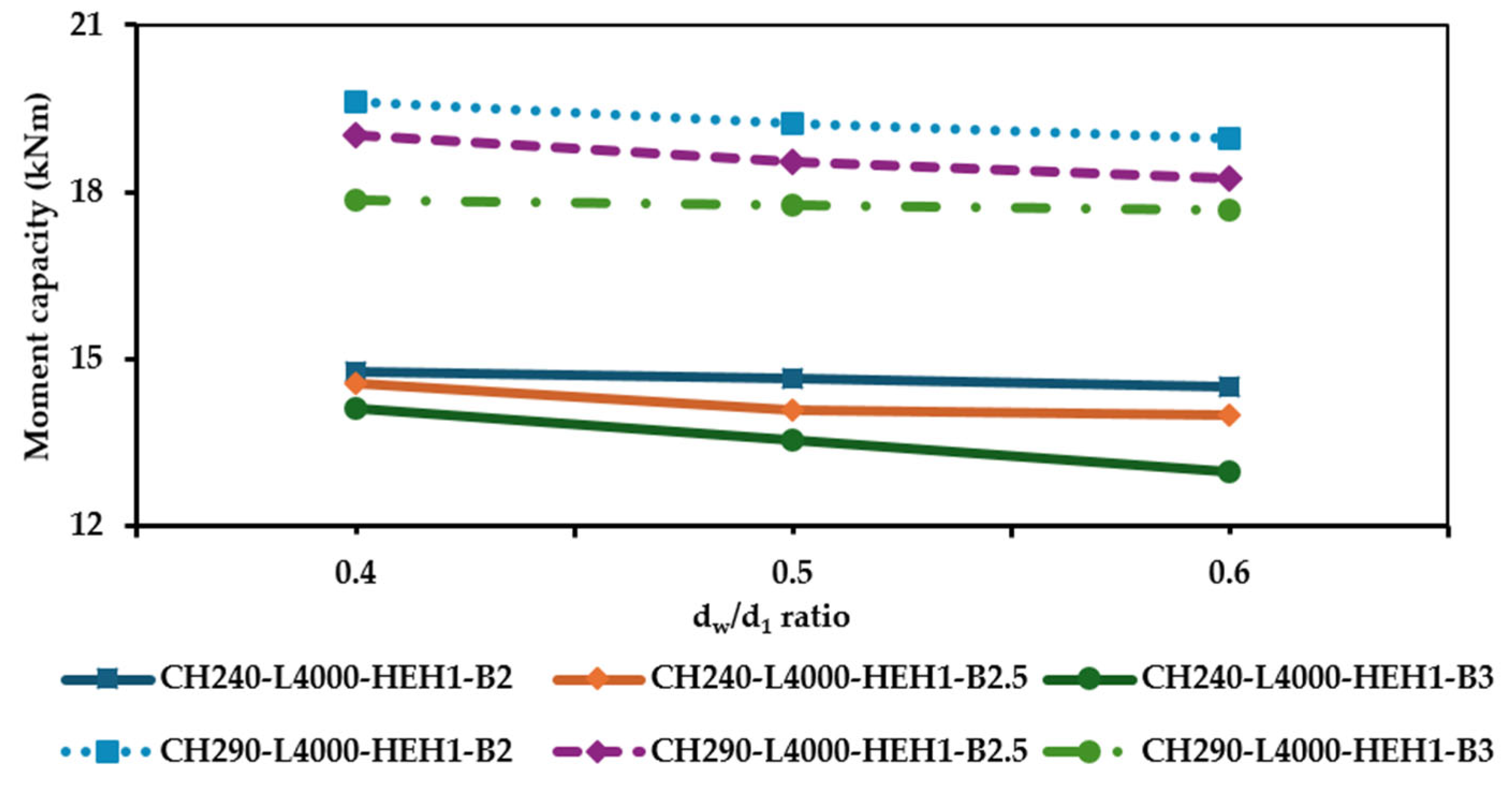
4.2. Findings and Interpretations
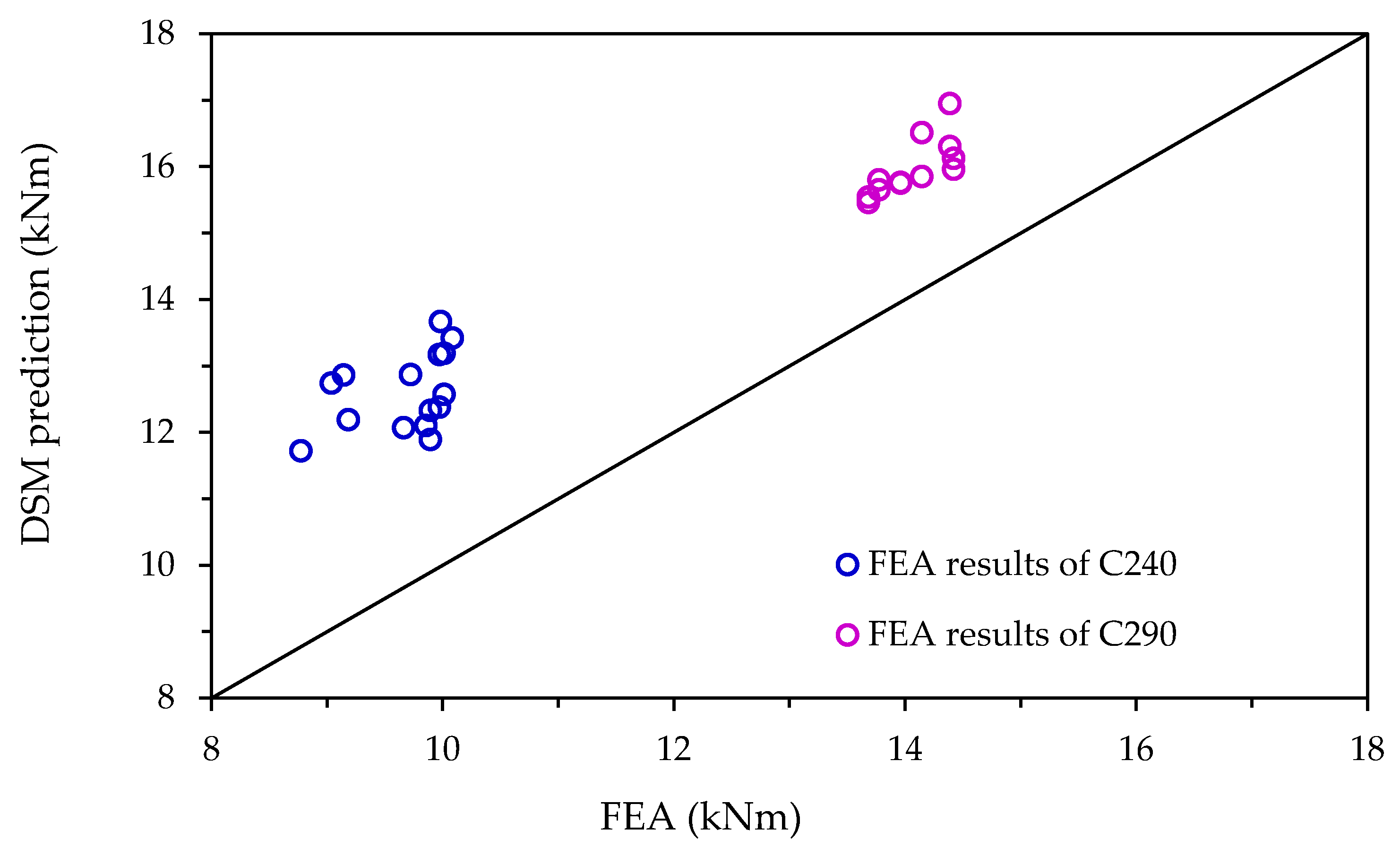
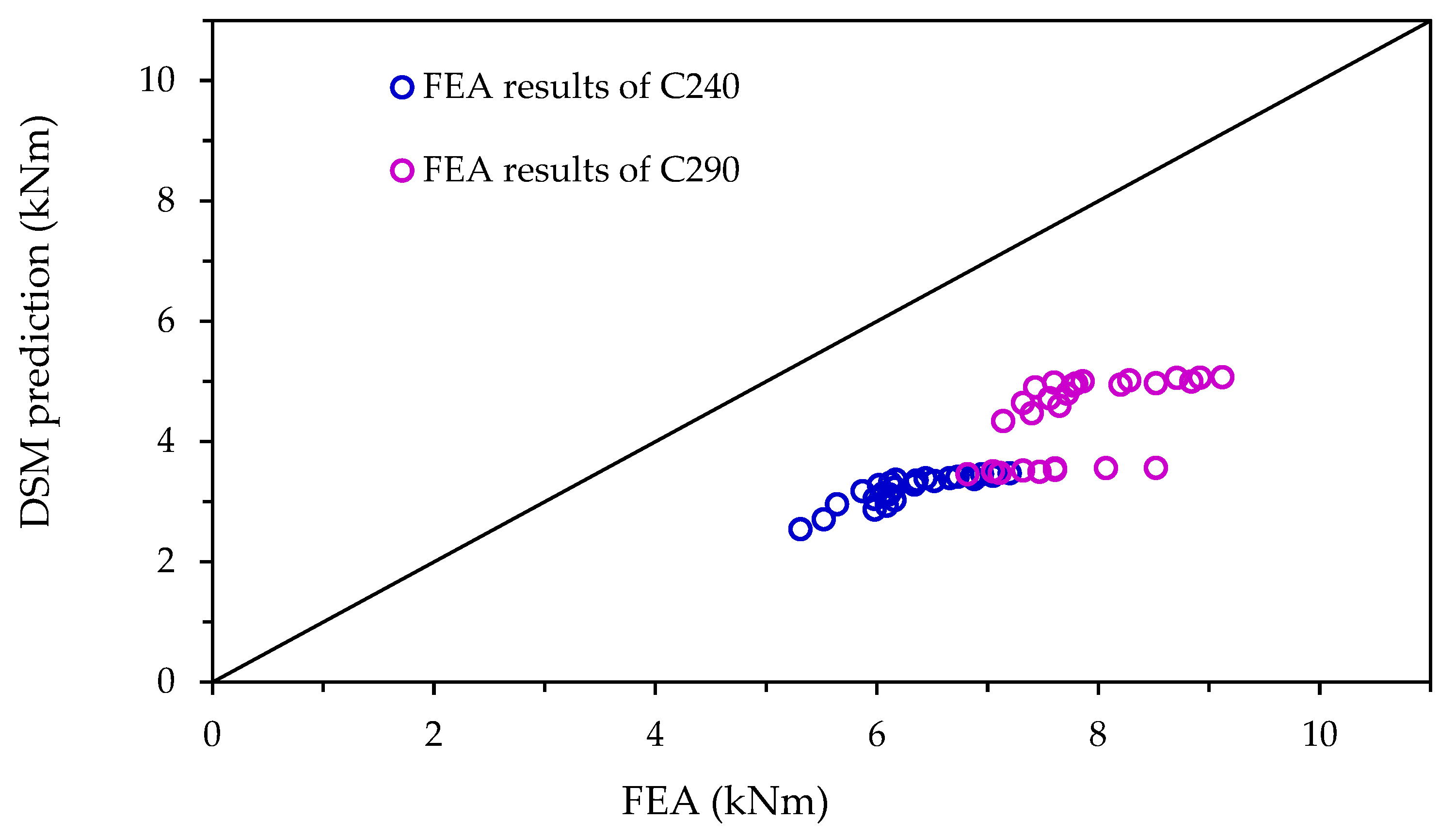
5. Comparison of FEA Results with the Existing Design Predictions
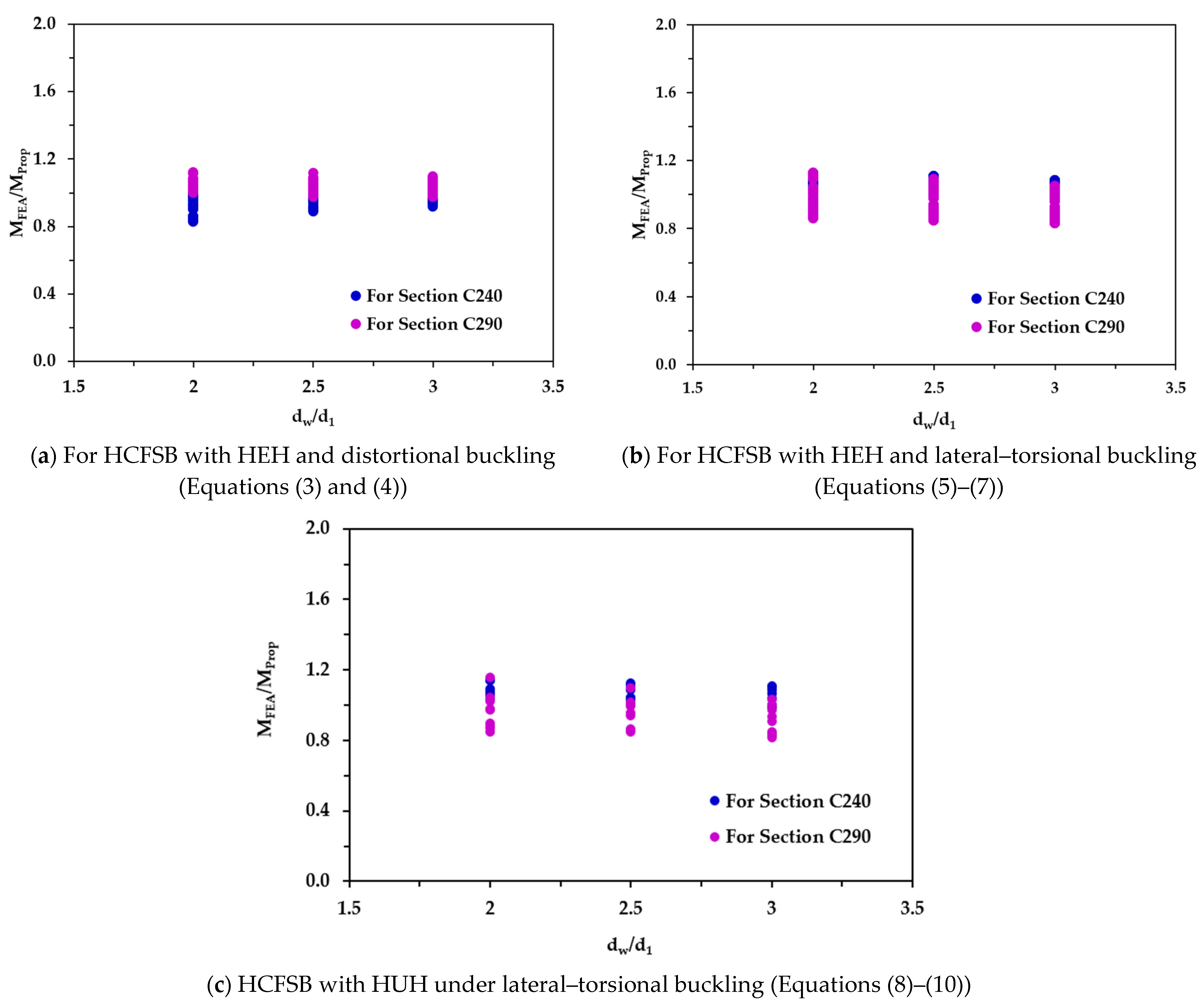
6. Recommended Design Equation
6.1. Distortional–Buckling Strength
- denotes the predicted flexural strength against distortional failure;
- is the elastic distortional buckling moment for HUH sections;
- and represent the yield moments of the gross and net sections, respectively, where ;
- is the yield strength of the steel;
6.2. Lateral–Torsional Buckling Strength
- is the proposed bending capacity under lateral–torsional buckling;
- is the net section yield capacity;
- denotes the corresponding elastic lateral–torsional buckling strength for an HCFSB with HUH.
7. Reliability Assessment
8. Conclusions
- (1)
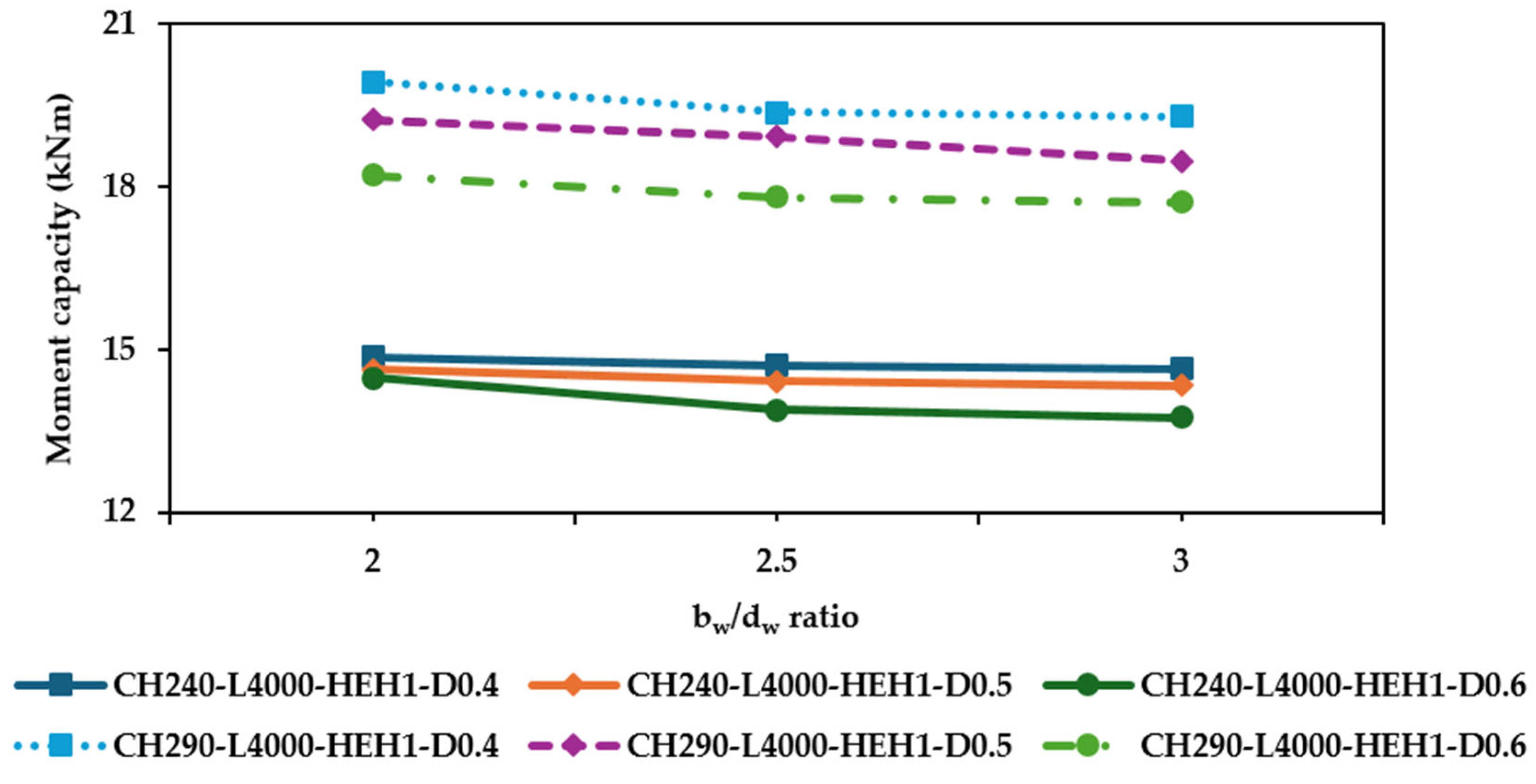
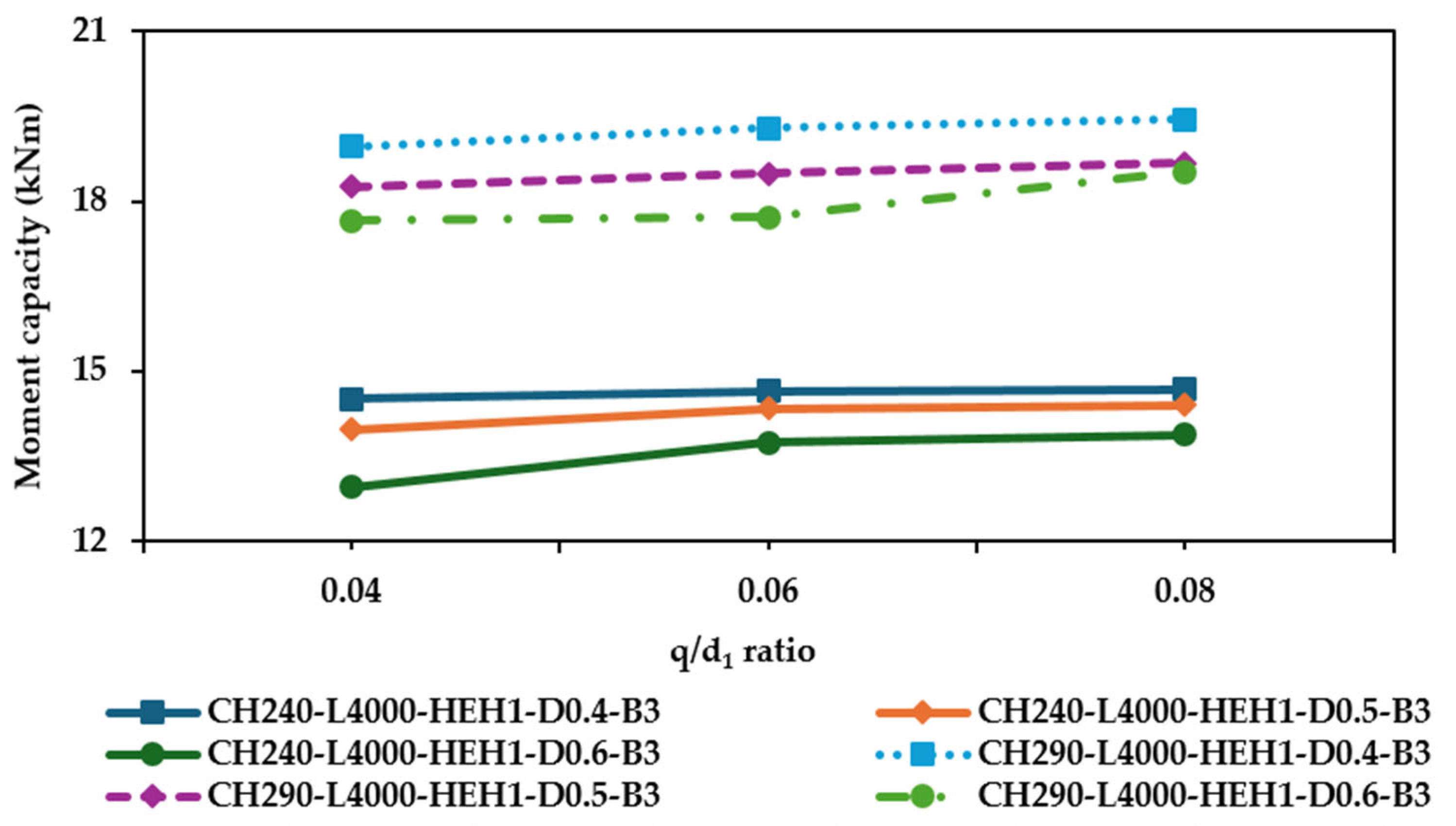
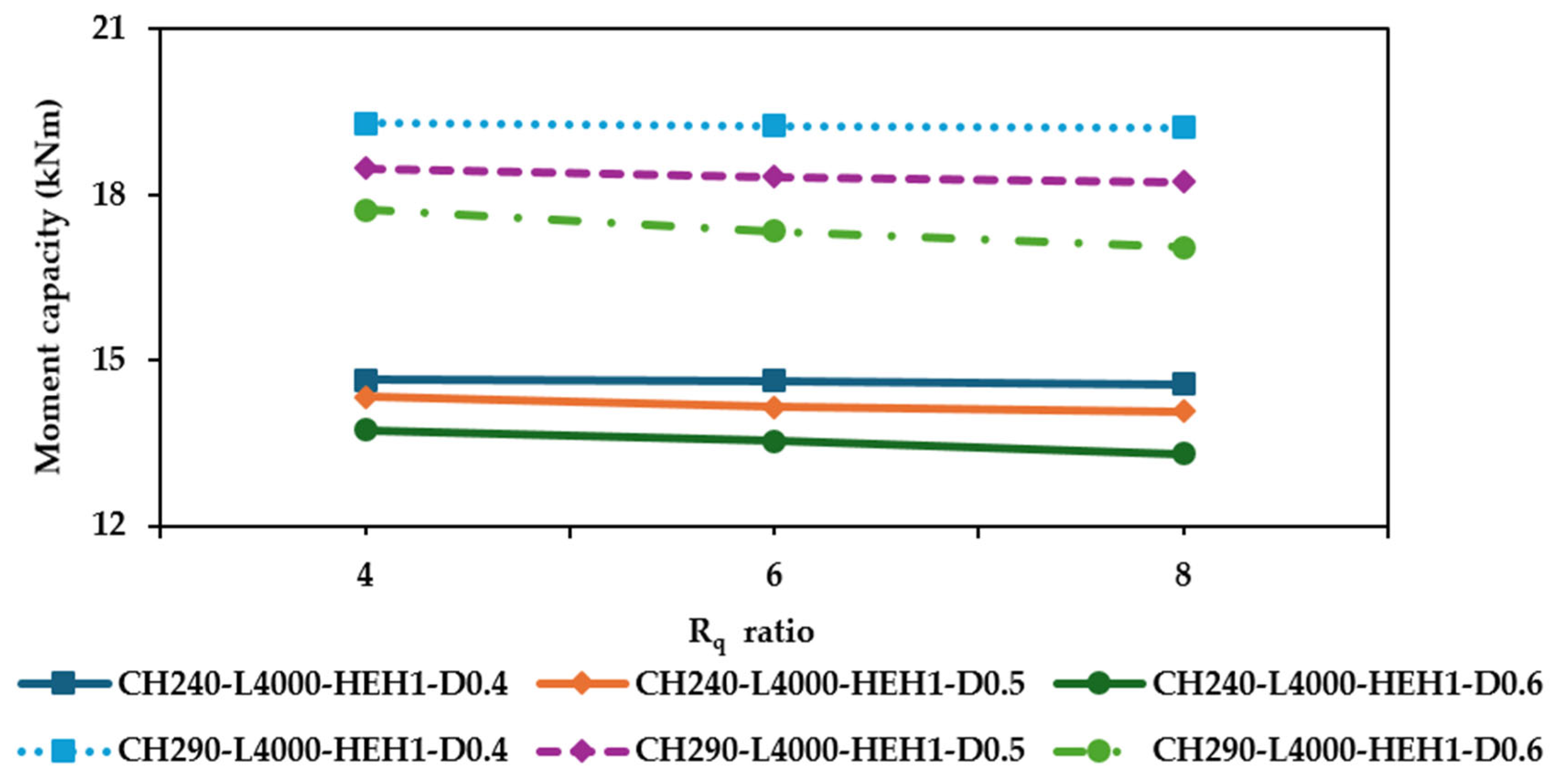
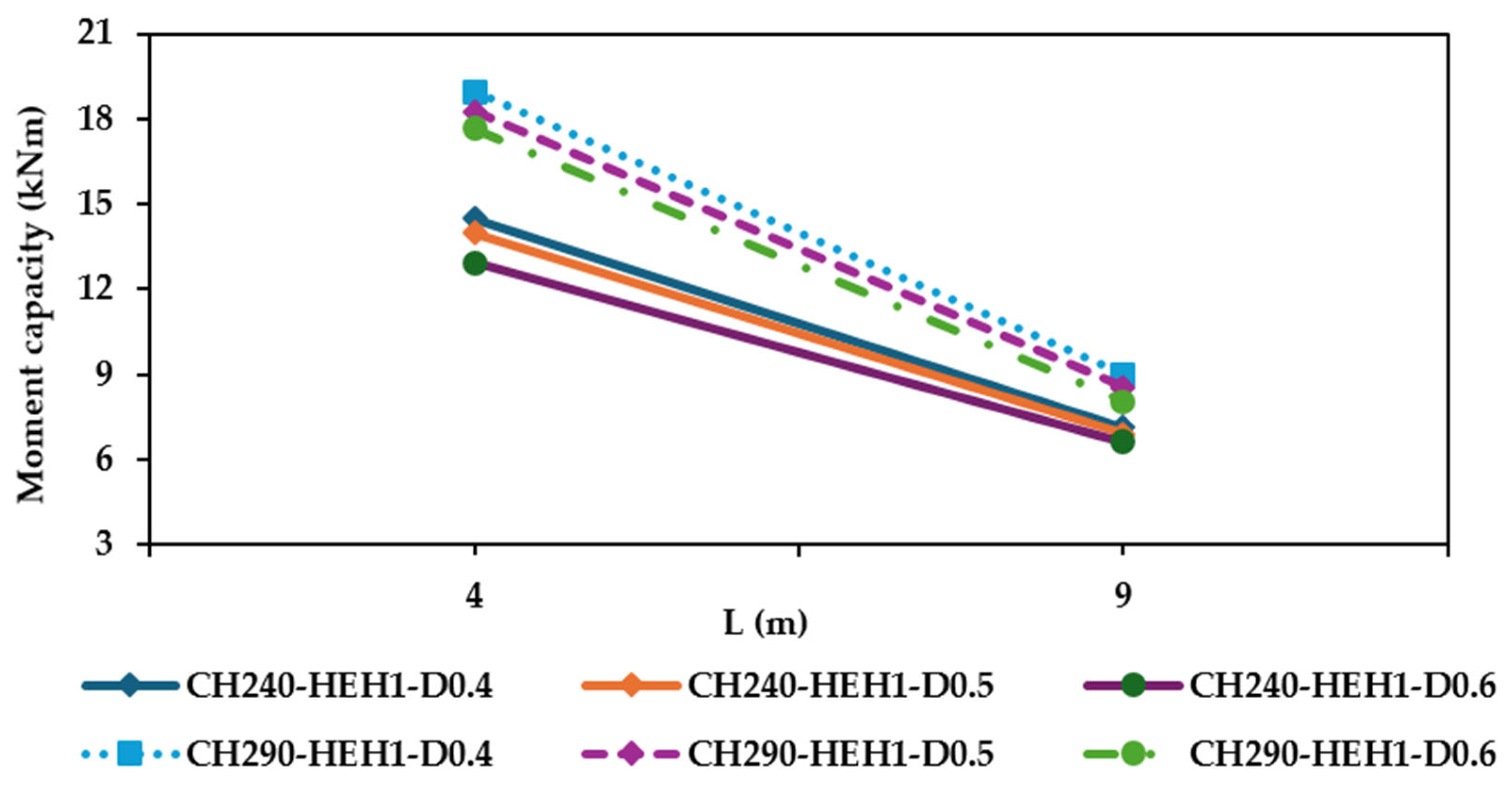
- Enhanced flexural capacity through edge stiffening: The finite element simulations showed that HCFSBs with HEH configurations exhibited, on average, a 10% higher bending capacity compared to those with HUH. Among the parameters analysed, factors such as dw/d1, section depth (d), and beam span (L) significantly influenced the flexural strength, whereas the web hole radius ratio (Rq) had minimal effect.
- (2)
- Identified shortcomings of current DSM design provisions: A comparative analysis revealed that the current DSM-based design provisions significantly underestimate the bending strength of HCFSBs with HUH sections. The predicted capacities were found to be 23% and 47% lower than FEA results for distortional and lateral–torsional buckling cases, respectively.
- (3)
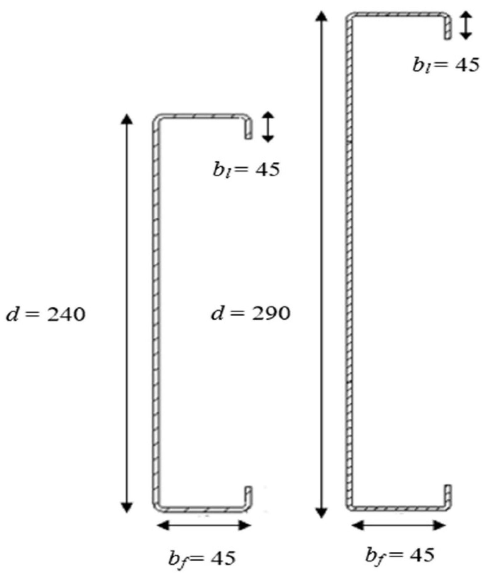
- Development of modified DSM design equations: Utilizing FEA data, new DSM-oriented expressions were developed for estimating the moment resistance of HCFSBs with both HUH and HEH web hole configurations. These equations are valid for beams having the following ranges: (1) 240 mm≤ d ≤ 290 mm, (2) 0.4≤ dw/d1 ≤ 0.6, (3) 2.00 ≤ bw/dw ≤ 3.00, (4) 0.04 ≤ q/d1 ≤ 0.08, and (5) 4000 mm≤ L ≤ 9000 mm.
- (4)
- Reliability verification of proposed formulations: The performance of the proposed DSM formulations for HCFSBs with HEH was verified through reliability analysis. The outcomes confirmed that the revised equations yield dependable estimates of flexural strength within acceptable safety margins.
- Future Research Directions:
- Experimental Validation: the findings should be corroborated through full-scale physical testing, especially for HEH configurations, to confirm model predictions and ensure applicability across diverse fabrication conditions.
- Sensitivity to Manufacturing Tolerances: future studies should assess how geometric imperfections from manufacturing (e.g., hole placement errors, edge quality) affect performance, particularly for thin-walled sections.
- Dynamic and Seismic Loading: investigation into the performance of these perforated beams under cyclic, fatigue, or seismic loads is essential for comprehensive design guidance.
- Integration into Codes: further collaboration with standards committees (e.g., AISI, AS/NZS) will be needed to validate these findings for formal inclusion in design codes.
Author Contributions
Funding
Data Availability Statement
Conflicts of Interest
References
- Chen, B.; Roy, K.; Uzzaman, A.; Lim, J.B. Moment capacity of cold-formed channel beams with edge-stiffened web holes, un-stiffened web holes and plain webs. Thin-Walled Struct. 2020, 157, 107070. [Google Scholar] [CrossRef]
- Yu, C. Cold-formed steel flexural member with edge stiffened holes: Behaviour, optimization, and design. J. Constr. Steel Res. 2012, 71, 210–218. [Google Scholar] [CrossRef]
- Thirunavukkarasu, K.; Kanthasamy, E.; Poologanathan, K.; Gunalan, S.; Gatheeshgar, P.; Tsavdaridis, K.D.; Corradi, M. Flexural behaviour and design rules for SupaCee sections with web openings. J. Build. Eng. 2023, 63, 105539. [Google Scholar] [CrossRef]
- Chen, B.; Roy, K.; Fang, Z.; Uzzaman, A.; Raftery, G.; Lim, J.B. Moment capacity of back-to-back cold-formed steel channels with edge-stiffened holes, un-stiffened holes, and plain webs. Eng. Struct. 2021, 235, 112042. [Google Scholar] [CrossRef]
- Dai, Y.; Roy, K.; Fang, Z.; Chen, B.; Raftery, G.M.; Lim, J.B. A novel machine learning model to predict the moment capacity of cold-formed steel channel beams with edge-stiffened and un-stiffened web holes. J. Build. Eng. 2022, 53, 104592. [Google Scholar] [CrossRef]
- Chen, B.; Roy, K.; Fang, Z.; Uzzaman, A.; Pham, C.H.; Raftery, G.M.; Lim, J.B. Shear capacity of cold-formed steel channels with edge-stiffened web holes, unstiffened web holes, and plain webs. J. Struct. Eng. 2022, 148, 04021268. [Google Scholar] [CrossRef]
- Kanthasamy, E.; Thirunavukkarasu, K.; Poologanathan, K.; Gatheeshgar, P.; Todhunter, S.; Suntharalingam, T.; Ishqy, M.F.M. Shear behaviour of doubly symmetric rectangular hollow flange beam with circular edge-stiffened openings. Eng. Struct. 2022, 250, 113366. [Google Scholar] [CrossRef]
- Chen, B.; Roy, K.; Uzzaman, A.; Raftery, G.M.; Nash, D.; Clifton, G.C.; Lim, J.B. Effects of edge-stiffened web openings on the behaviour of cold-formed steel channel sections under compression. Thin-Walled Struct. 2019, 144, 106307. [Google Scholar] [CrossRef]
- Fang, Z.; Roy, K.; Chen, B.; Sham, C.W.; Hajirasouliha, I.; Lim, J.B. Deep learning-based procedure for structural design of cold-formed steel channel sections with edge-stiffened and un-stiffened holes under axial compression. Thin-Walled Struct. 2021, 166, 108076. [Google Scholar] [CrossRef]
- Uzzaman, A.; Lim, J.B.; Nash, D.; Roy, K. Cold-formed steel channel sections under end-two-flange loading condition: Design for edge-stiffened holes, unstiffened holes and plain webs. Thin-Walled Struct. 2020, 147, 106532. [Google Scholar] [CrossRef]
- Chen, B.; Roy, K.; Fang, Z.; Uzzaman, A.; Chi, Y.; Lim, J.B. Web crippling capacity of fastened cold-formed steel channels with edge-stiffened web holes, un-stiffened web holes and plain webs under two-flange loading. Thin-Walled Struct. 2021, 163, 107666. [Google Scholar] [CrossRef]
- Timoshenko, S.P.; James, M.G. Theory of Elastic Stability; McGraw-Hill Book Company: New York, NY, USA, 1961. [Google Scholar]
- AISI S100-16 2016; North American Specification for the Design of Cold-Formed Steel Structural Members. AISI (American Iron and Steel Institute): Washington, DC, USA, 2016.
- AS/NZS 4600 2018; Cold-Formed Steel Structures. AS/NZS (Australia/New Zealand Standard): Sydney, Australia, 2018.
- Wang, W.; Roy, K.; Fang, Z.; Ananthi, G.B.G.; Lim, J.B. Web crippling behaviour of cold-formed steel channel sections having elongated edge-stiffened web holes under interior-two-flange loading condition. Eng. Struct. 2023, 294, 116757. [Google Scholar] [CrossRef]
- Zhao, J.; Sun, K.; Yu, C.; Wang, J. Tests and direct strength design on cold-formed steel channel beams with web holes. Eng. Struct. 2019, 184, 434–446. [Google Scholar] [CrossRef]
- Moen, C.D.; Schudlich, A.; von der Heyden, A. Experiments on cold-formed steel C-section joists with unstiffened web holes. J. Struct. Eng. 2013, 139, 695–704. [Google Scholar] [CrossRef]
- Moen, C.D.; Schafer, B.W. Elastic buckling of cold-formed steel columns and beams with holes. Eng. Struct. 2009, 31, 2812–2824. [Google Scholar] [CrossRef]
- Degtyareva, N.; Gatheeshgar, P.; Poologanathan, K.; Gunalan, S.; Shyha, I.; McIntosh, A. Local buckling strength and design of cold-formed steel beams with slotted perforations. Thin-Walled Struct. 2020, 156, 106951. [Google Scholar] [CrossRef]
- Degtyareva, N.; Gatheeshgar, P.; Poologanathan, K.; Gunalan, S.; Tsavdaridis, K.D.; Napper, S. New distortional buckling design rules for slotted perforated cold-formed steel beams. J. Constr. Steel Res. 2020, 168, 106006. [Google Scholar] [CrossRef]
- Yu, N.T.; Kim, B.; Yuan, W.B.; Li, L.Y.; Yu, F. An analytical solution of distortional buckling resistance of cold-formed steel channel-section beams with web openings. Thin-Walled Struct. 2019, 135, 446–452. [Google Scholar] [CrossRef]
- Yu, N.T.; Kim, B.; Li, L.Y.; Hong, W.J.; Yuan, W.B. Distortional buckling of perforated cold-formed steel beams subject to uniformly distributed transverse loads. Thin-Walled Struct. 2020, 148, 106569. [Google Scholar] [CrossRef]
- Chandramohan, D.L.; Roy, K.; Fang, Z.; Ananthi, G.B.G.; Lim, J.B. Moment capacity of cold-formed steel channel beams with edge-stiffened and unstiffened elongated web holes. Thin-Walled Struct. 2025, 206, 112605. [Google Scholar] [CrossRef]
- Yu, C.; Schafer, B.W. Distortional buckling tests on cold-formed steel beams. J. Struct. Eng. 2006, 132, 515–528. [Google Scholar] [CrossRef]
- Yu, C.; Schafer, B.W. Simulation of cold-formed steel beams in local and distortional buckling with applications to the direct strength method. J. Constr. Steel Res. 2007, 63, 581–590. [Google Scholar] [CrossRef]
- Wang, L.; Young, B. Design of cold-formed steel channels with stiffened webs subjected to bending. Thin-Walled Struct. 2014, 85, 81–92. [Google Scholar] [CrossRef]
- Kankanamge, N.D.; Mahendran, M. Behaviour and design of cold-formed steel beams subject to lateral–torsional buckling. Thin-Walled Struct. 2012, 51, 25–38. [Google Scholar] [CrossRef]
- Haidarali, M.R.; Nethercot, D.A. Finite element modelling of cold-formed steel beams under local buckling or combined local/distortional buckling. Thin-Walled Struct. 2011, 49, 1554–1562. [Google Scholar] [CrossRef]
- Anbarasu, M. Local-distortional buckling interaction on cold-formed steel lipped channel beams. Thin-Walled Struct. 2016, 98, 351–359. [Google Scholar] [CrossRef]
- Yu, C.; Yan, W. Effective Width Method for determining distortional buckling strength of cold-formed steel flexural C and Z sections. Thin-Walled Struct. 2011, 49, 233–238. [Google Scholar] [CrossRef]
- Pham, D.K.; Pham, C.H.; Pham, S.H.; Hancock, G.J. Experimental investigation of high strength cold-formed channel sections in shear with rectangular and slotted web openings. J. Constr. Steel Res. 2020, 165, 105889. [Google Scholar] [CrossRef]
- Pham, D.K.; Pham, C.H.; Hancock, G.J. Parametric study for shear design of cold-formed channels with elongated web openings. J. Constr. Steel Res. 2020, 172, 106222. [Google Scholar] [CrossRef]
- Sivakumaran, K.S.; Abdel-Rahman, N. A finite element analysis model for the behaviour of cold-formed steel members. Thin-Walled Struct. 1998, 31, 305–324. [Google Scholar] [CrossRef]
- Moen, C.D.; Schafer, B.W. Impact of holes on the elastic buckling of cold-formed steel columns with application to the direct strength method. In Proceedings of the International Specialty Conference on Cold-Formed Steel Structures, Orlando, FL, USA, 26–27 October 2006; Volume 2. [Google Scholar]
- Moen, C.D.; Schafer, B.W. Experiments on cold-formed steel columns with holes. Thin-Walled Struct. 2008, 46, 1164–1182. [Google Scholar] [CrossRef]
- Xu, L.; Shi, Y.; Yang, S. Compressive strength of cold-formed steel c-shape columns with slotted holes. In Proceedings of the International Specialty Conference on Cold-Formed Steel Structures, St. Louis, MI, USA, 5–6 November 2014; Volume 4. [Google Scholar]
- Zhao, J.; Liu, S.; Chen, B. Axial strength of slotted perforated cold-formed steel channels under pinned-pinned boundary conditions. J. Constr. Steel Res. 2023, 200, 107673. [Google Scholar] [CrossRef]
- Chandramohan, D.L.; Roy, K.; Fang, Z.; Ananthi, G.B.G.; Lim, J.B. Numerical investigation of cold-formed steel channels with edge-stiffened and unstiffened elongated web holes under shear. Thin-Walled Struct. 2024, 196, 111472. [Google Scholar] [CrossRef]
- Chandramohan, D.L.; Roy, K.; Ananthi, G.B.G.; Fang, Z.; Lim, J.B. Structural behaviour and capacity of cold-formed steel channel sections with elongated edge-stiffened and unstiffened web holes under compression. J. Constr. Steel Res. 2024, 218, 108681. [Google Scholar] [CrossRef]
- Wang, W.; Roy, K.; Fang, Z.; Ananthi, G.B.G.; Lim, J.B. Web crippling behaviour of cold-formed steel channels with elongated un-stiffened and edge-stiffened web holes under end-two-flange loading condition. Thin-Walled Struct. 2024, 195, 111398. [Google Scholar] [CrossRef]
- Lawson, R.M.; Stergiopoulos, M.; Rowell, M. Design of cold formed C section beams with elongated circular openings based on tests. Thin-Walled Struct. 2024, 204, 112256. [Google Scholar] [CrossRef]
- Wang, H.; Yang, H.; Qian, H.; Chen, D.; Jin, X.; Fan, F. Static experimental analysis and optimization of innovative pre-engineered tubular section beam-column connections in cold-form steel frames. J. Build. Eng. 2022, 48, 103989. [Google Scholar] [CrossRef]
- Yang, H.; Wang, H.; Qian, H.; Jin, X.; Chen, D.; He, Y.; Li, Q.; Fan, F. Mechanical performance of pre-engineered closed section beam-column connections in CFS frames: Experimental investigation. Structures 2022, 39, 164–174. [Google Scholar] [CrossRef]
- Yang, H. Performance analysis of semi-rigid connections in prefabricated high-rise steel structures. Structures 2020, 28, 837–846. [Google Scholar] [CrossRef]
- Huangfu, S.E.; Tao, Z.; Zhang, J.; Abdul Ghafar, W.; Wang, Z.; Ye, C.; Hasan, M.M. Flexural Behavior of Stainless Steel V-Stiffened Lipped Channel Beams. Metals 2023, 13, 434. [Google Scholar] [CrossRef]
- ABAQUS Analysis User’s Manual-Version; ABAQUS Inc.: Palo Alto, CA, USA, 2020.


| Specimen Details | Flexural Strength | |||||||||
|---|---|---|---|---|---|---|---|---|---|---|
| Depth of wb d | Length L | Section Thickness t | Hole Depth dw | Hole Spacing | Hole Depth Ratio dw/d1 | Length of Stiffener q | Test Results MEXP | FE Analysis MFEA | MEXP/MFEA | Failure Patterns * |
| (mm) | (mm) | (mm) | (mm) | (mm) | (kNm) | (kNm) | ||||
| 290 | 4000 | 2.11 | 140 | - | 0.49 | - | 16.7 | 17.9 | 0.93 | D + L |
| 290 | 4000 | 2.11 | 140 | 100 | 0.49 | - | 16.3 | 17.6 | 0.92 | D + L |
| 290 | 4000 | 2.11 | 140 | 50 | 0.49 | - | 15.7 | 16.5 | 0.95 | D + L |
| 290 | 4000 | 2.11 | 140 | - | 0.49 | 13 | 19.3 | 20.5 | 0.94 | D + L |
| 290 | 4000 | 2.11 | 140 | 100 | 0.49 | 13 | 19.8 | 21.2 | 0.93 | D + L |
| 290 | 4000 | 2.11 | 140 | 50 | 0.49 | 13 | 20.5 | 21.7 | 0.94 | D + L |
| Average value | 0.93 | |||||||||
| Variation coefficient | 0.04 | |||||||||
| (a) | ||||||||||
| Specimen | FEA-Based Flexural Strength (MFEA (kNm)) for CFSCB’s Featuring HUH and HEH | |||||||||
| HUH | HEH | |||||||||
| q/d1: 0.04 | q/d1: 0.06 | q/d1: 0.08 | ||||||||
| rq: 2 | rq: 4 | rq: 6 | rq: 2 | rq: 4 | rq: 6 | rq: 2 | rq: 4 | rq: 6 | ||
| CH240-L4000-HEH1-D0.4-B2 | 13.67 | 14.77 | 14.73 | 14.68 | 14.86 | 14.83 | 14.78 | 14.88 | 14.86 | 14.82 |
| CH240-L4000-HEH3-D0.4-B2 | 13.17 | 14.24 | 14.19 | 14.11 | 14.44 | 14.41 | 14.43 | 14.70 | 14.66 | 14.60 |
| CH240-L4000-HEH1-D0.4-B2.5 | 13.42 | 14.65 | 14.61 | 14.53 | 14.70 | 14.68 | 14.64 | 14.75 | 14.73 | 14.69 |
| CH240-L4000-HEH3-D0.4-B2.5 | 12.33 | 13.39 | 13.34 | 13.24 | 13.65 | 13.48 | 13.40 | 14.38 | 14.31 | 14.30 |
| CH240-L4000-HEH1-D0.4-B3 | 12.57 | 14.50 | 14.45 | 14.41 | 14.64 | 14.62 | 14.57 | 14.68 | 14.66 | 14.63 |
| CH240-L4000-HEH3-D0.4-B3 | 12.10 | 13.20 | 13.13 | 13.01 | 13.47 | 13.37 | 13.27 | 14.28 | 14.25 | 14.14 |
| CH240-L4000-HEH1-D0.5-B2 | 13.19 | 14.54 | 14.44 | 14.26 | 14.63 | 14.57 | 14.51 | 14.78 | 14.59 | 14.48 |
| CH240-L4000-HEH3-D0.5-B2 | 12.87 | 14.18 | 14.07 | 13.93 | 14.28 | 14.21 | 14.08 | 14.35 | 14.27 | 14.16 |
| CH240-L4000-HEH1-D0.5-B2.5 | 12.38 | 14.08 | 14.03 | 14.02 | 14.41 | 14.20 | 14.16 | 14.58 | 14.37 | 14.34 |
| CH240-L4000-HEH3-D0.5-B2.5 | 12.07 | 13.90 | 13.76 | 13.53 | 14.09 | 13.99 | 13.88 | 14.18 | 14.09 | 13.98 |
| CH240-L4000-HEH1-D0.5-B3 | 11.89 | 13.97 | 13.84 | 13.62 | 14.34 | 14.15 | 14.08 | 14.40 | 14.29 | 14.03 |
| CH240-L4000-HEH1-D0.6-B2 | 12.79 | 14.10 | 13.90 | 13.70 | 14.48 | 14.09 | 13.89 | 14.71 | 14.43 | 13.98 |
| CH240-L4000-HEH3-D0.6-B2 | 11.72 | 13.49 | 13.31 | 13.22 | 13.66 | 13.53 | 13.30 | 13.73 | 13.61 | 13.23 |
| CH240-L4000-HEH1-D0.6-B2.5 | 12.56 | 13.52 | 13.41 | 13.32 | 13.88 | 13.65 | 13.49 | 13.98 | 13.87 | 13.74 |
| CH240-L4000-HEH1-D0.6-B3 | 12.04 | 12.95 | 12.79 | 12.52 | 13.74 | 13.54 | 13.31 | 13.87 | 13.61 | 13.44 |
| CH290-L4000-HEH1-D0.4-B2 | 16.95 | 19.63 | 19.57 | 19.54 | 19.93 | 19.83 | 19.72 | 20.03 | 19.97 | 19.86 |
| CH290-L4000-HEH3-D0.4-B2 | 16.51 | 18.94 | 18.86 | 18.81 | 19.22 | 19.15 | 19.03 | 19.38 | 19.25 | 19.13 |
| CH290-L4000-HEH1-D0.4-B2.5 | 16.30 | 19.23 | 19.20 | 19.09 | 19.37 | 19.33 | 19.31 | 19.45 | 19.40 | 19.35 |
| CH290-L4000-HEH3-D0.4-B2.5 | 15.75 | 18.73 | 18.65 | 18.49 | 19.17 | 19.06 | 18.86 | 19.24 | 19.10 | 18.99 |
| CH290-L4000-HEH1-D0.4-B3 | 16.12 | 18.97 | 18.92 | 18.77 | 19.29 | 19.25 | 19.22 | 19.44 | 19.32 | 19.26 |
| CH290-L4000-HEH1-D0.5-B2 | 15.96 | 19.01 | 18.95 | 18.22 | 19.23 | 19.11 | 18.88 | 19.30 | 19.24 | 19.03 |
| CH290-L4000-HEH3-D0.5-B2 | 15.46 | 17.34 | 17.17 | 16.93 | 17.60 | 17.47 | 17.25 | 17.80 | 17.59 | 17.40 |
| CH290-L4000-HEH1-D0.5-B2.5 | 15.85 | 18.55 | 18.38 | 18.17 | 18.93 | 18.89 | 18.67 | 19.21 | 19.11 | 19.92 |
| CH290-L4000-HEH1-D0.5-B3 | 15.80 | 18.25 | 18.07 | 17.92 | 18.48 | 18.33 | 18.24 | 18.68 | 18.42 | 18.26 |
| CH290-L4000-HEH1-D0.6-B2 | 15.76 | 17.86 | 17.49 | 17.02 | 18.21 | 18.99 | 18.62 | 18.49 | 18.17 | 17.83 |
| CH290-L4000-HEH1-D0.6-B2.5 | 15.65 | 17.77 | 16.92 | 16.49 | 17.81 | 17.64 | 17.41 | 18.24 | 18.94 | 18.65 |
| CH290-L4000-HEH1-D0.6-B3 | 15.54 | 17.66 | 17.42 | 17.01 | 17.72 | 17.34 | 17.05 | 18.72 | 18.60 | 18.37 |
| (b) | ||||||||||
| Specimen | FEA-Based Flexural Strength (MFEA (kNm)) for CFSCB’s Featuring HEH | |||||||||
| HUH | HEH | |||||||||
| q/d1: 0.04 | q/d1: 0.06 | q/d1: 0.08 | ||||||||
| rq: 2 | rq: 4 | rq: 6 | rq: 2 | rq: 4 | rq: 6 | rq: 2 | rq: 4 | rq: 6 | ||
| CH240-L9000-HEH1-D0.4-B2 | 7.20 | 7.34 | 7.28 | 7.27 | 7.37 | 7.33 | 7.32 | 7.39 | 7.36 | 7.35 |
| CH240-L9000-HEH3-D0.4-B2 | 6.73 | 7.02 | 6.99 | 6.97 | 7.12 | 7.09 | 7.07 | 7.21 | 7.18 | 7.16 |
| CH240-L9000-HEH5-D0.4-B2 | 6.36 | 6.80 | 6.75 | 6.71 | 6.95 | 6.91 | 6.87 | 7.09 | 7.05 | 7.01 |
| CH240-L9000-HEH1-D0.4-B2.5 | 7.08 | 7.20 | 7.21 | 7.20 | 7.27 | 7.26 | 7.25 | 7.31 | 7.30 | 7.29 |
| CH240-L9000-HEH3-D0.4-2.5 | 6.44 | 6.83 | 6.79 | 6.69 | 6.97 | 6.94 | 6.91 | 7.08 | 7.05 | 7.02 |
| CH240-L9000-HEH5-D0.4-2.5 | 6.12 | 6.60 | 6.55 | 6.53 | 6.81 | 6.76 | 6.73 | 6.97 | 6.93 | 6.90 |
| CH240-L9000-HEH1-D0.4-B3 | 6.95 | 7.13 | 7.11 | 7.0 | 7.20 | 7.19 | 7.18 | 7.25 | 7.24 | 7.23 |
| CH240-L9000-HEH3-D0.4-B3 | 6.17 | 6.64 | 6.59 | 6.55 | 6.82 | 6.79 | 6.76 | 6.96 | 6.93 | 6.90 |
| CH240-L9000-HEH5-D0.4-B3 | 6.02 | 6.56 | 6.54 | 6.50 | 6.79 | 6.76 | 6.76 | 6.97 | 6.94 | 6.94 |
| CH240-L9000-HEH1- D0.5-B2 | 7.05 | 7.20 | 7.19 | 7.18 | 7.25 | 7.24 | 7.23 | 7.29 | 7.28 | 7.27 |
| CH240-L9000-HEH3-D0.5-B2 | 6.34 | 6.74 | 6.72 | 6.71 | 6.88 | 6.86 | 6.82 | 7.00 | 6.96 | 6.94 |
| CH240-L9000-HEH5-D0.5-B2 | 6.06 | 6.48 | 6.45 | 6.42 | 6.69 | 6.65 | 6.63 | 6.86 | 6.82 | 6.80 |
| CH240-L9000-HEH1-D0.5-B2.5 | 6.86 | 7.06 | 7.05 | 7.03 | 7.14 | 7.12 | 7.11 | 7.19 | 7.18 | 7.17 |
| CH240-L9000-HEH3-D0.5-B2.5 | 6.16 | 6.49 | 6.45 | 6.43 | 6.69 | 6.66 | 6.63 | 6.84 | 6.81 | 6.78 |
| CH240-L9000-HEH5-D0.5-B2.5 | 5.98 | 6.43 | 6.42 | 6.40 | 6.67 | 6.65 | 6.60 | 6.81 | 6.80 | 6.78 |
| CH240-L9000-HEH1-D0.5-B3 | 6.66 | 6.90 | 6.87 | 6.85 | 7.01 | 6.99 | 6.97 | 7.08 | 7.07 | 7.05 |
| CH240-L9000-HEH3-D0.5-B3 | 5.87 | 6.32 | 6.31 | 6.30 | 6.57 | 6.56 | 6.55 | 6.74 | 6.73 | 6.72 |
| CH240-L9000-HEH5-D0.5-B3 | 5.64 | 5.95 | 5.92 | 5.90 | 6.25 | 6.23 | 6.21 | 6.48 | 6.45 | 6.41 |
| CH240-L9000-HEH1-D0.6-B2 | 6.88 | 7.07 | 7.06 | 7.06 | 7.14 | 7.13 | 7.12 | 7.19 | 7.18 | 7.18 |
| CH240-L9000-HEH3-D0.6-B2 | 6.11 | 6.50 | 6.47 | 6.46 | 6.67 | 6.64 | 6.62 | 6.82 | 6.79 | 6.76 |
| CH240-L9000-HEH5-D0.6-B2 | 5.98 | 6.24 | 6.21 | 6.19 | 6.35 | 6.31 | 6.29 | 6.48 | 6.45 | 6.41 |
| CH240-L9000-HEH1-D0.6-B2.5 | 6.52 | 6.89 | 6.85 | 6.83 | 6.97 | 6.96 | 6.94 | 7.05 | 7.03 | 7.02 |
| CH240-L9000-HEH3-D0.6-B2.5 | 6.16 | 6.36 | 6.34 | 6.32 | 6.54 | 6.52 | 6.51 | 6.71 | 6.69 | 6.67 |
| CH240-L9000-HEH5-D0.6-B2.5 | 5.52 | 5.94 | 5.90 | 5.98 | 6.20 | 6.17 | 6.02 | 6.35 | 6.31 | 6.28 |
| CH240-L9000-HEH1-D0.6-B3 | 6.34 | 6.61 | 6.59 | 6.57 | 6.75 | 6.74 | 6.72 | 6.86 | 6.85 | 6.84 |
| CH240-L9000-HEH3-D0.6-B3 | 6.09 | 6.05 | 6.01 | 5.98 | 6.19 | 6.14 | 6.12 | 6.25 | 6.23 | 6.21 |
| CH240-L9000-HEH5-D0.6-B3 | 5.31 | 5.65 | 5.63 | 5.61 | 5.85 | 5.83 | 5.81 | 5.94 | 5.92 | 5.90 |
| CH290-L9000-HEH1-D0.4-B2 | 9.12 | 9.32 | 9.30 | 9.29 | 9.39 | 9.37 | 9.36 | 9.45 | 9.43 | 9.42 |
| CH290-L9000-HEH3-D0.4-B2 | 8.28 | 8.84 | 8.79 | 8.76 | 9.03 | 8.99 | 8.96 | 9.20 | 9.16 | 9.13 |
| CH290-L9000-HEH5-D0.4-B2 | 7.80 | 8.57 | 8.52 | 8.49 | 8.87 | 8.82 | 8.78 | 8.96 | 8.94 | 8.91 |
| CH290-L9000-HEH1-D0.4-B2.5 | 8.92 | 9.17 | 9.14 | 9.12 | 9.26 | 9.24 | 9.22 | 9.34 | 9.32 | 9.31 |
| CH290-L9000-HEH3-D0.4-B2.5 | 7.86 | 8.54 | 8.49 | 8.45 | 8.80 | 8.76 | 8.72 | 9.02 | 8.98 | 8.94 |
| CH290-L9000-HEH5-D0.4-B2.5 | 7.77 | 8.36 | 8.35 | 8.34 | 8.51 | 8.48 | 8.47 | 8.78 | 8.73 | 8.69 |
| CH290-L9000-HEH1-D0.4-B3 | 8.71 | 9.00 | 8.97 | 8.94 | 9.13 | 9.10 | 9.07 | 9.23 | 9.20 | 9.18 |
| CH290-L9000-HEH3-D0.4-B3 | 7.60 | 8.32 | 8.26 | 8.24 | 8.65 | 8.61 | 8.58 | 8.91 | 8.88 | 8.85 |
| CH290-L9000-HEH5-D0.4-B3 | 7.43 | 8.18 | 8.14 | 8.12 | 8.33 | 8.29 | 8.27 | 8.46 | 8.43 | 8.41 |
| CH290-L9000-HEH1-D0.5-B2 | 8.84 | 9.12 | 9.11 | 9.09 | 9.22 | 9.21 | 9.19 | 9.30 | 9.29 | 9.27 |
| CH290-L9000-HEH3-D0.5-B2 | 7.72 | 8.44 | 8.40 | 8.38 | 8.70 | 8.67 | 8.65 | 8.92 | 8.89 | 8.87 |
| CH290-L9000-HEH5-D0.5-B2 | 7.65 | 8.35 | 8.33 | 8.31 | 8.56 | 8.53 | 8.52 | 8.78 | 8.75 | 8.73 |
| CH290-L9000-HEH1-D0.5-B2.5 | 8.52 | 8.87 | 8.85 | 8.82 | 9.01 | 8.99 | 8.97 | 9.12 | 9.10 | 9.08 |
| CH290-L9000-HEH3-D0.5-B2.5 | 7.56 | 8.23 | 8.21 | 8.20 | 8.45 | 8.43 | 8.41 | 8.78 | 8.76 | 8.75 |
| CH290-L9000-HEH5-D0.5-B2.5 | 7.40 | 7.86 | 7.83 | 7.82 | 8.08 | 8.04 | 8.02 | 8.25 | 8.23 | 8.21 |
| CH290-L9000-HEH1-D0.5-B3 | 8.20 | 8.57 | 8.54 | 8.50 | 8.76 | 8.73 | 8.70 | 8.91 | 8.88 | 8.86 |
| CH290-L9000-HEH3-D0.5-B3 | 7.32 | 8.18 | 8.14 | 8.12 | 8.29 | 8.26 | 8.24 | 8.38 | 8.35 | 8.33 |
| CH290-L9000-HEH5-D0.5-B3 | 7.14 | 7.75 | 7.72 | 7.70 | 7.84 | 7.81 | 7.79 | 8.06 | 8.02 | 7.99 |
| CH290-L9000-HEH1-D0.6-B2 | 8.52 | 8.89 | 8.87 | 8.86 | 9.03 | 9.01 | 9.00 | 9.13 | 9.12 | 9.11 |
| CH290-L9000-HEH3-D0.6-B2 | 7.61 | 8.26 | 8.24 | 8.23 | 8.54 | 8.52 | 8.50 | 8.76 | 8.74 | 8.72 |
| CH290-L9000-HEH5-D0.6-B2 | 7.47 | 8.18 | 8.15 | 8.12 | 8.24 | 8.21 | 8.19 | 8.45 | 8.43 | 8.40 |
| CH290-L9000-HEH1-D0.6-B2.5 | 8.07 | 8.50 | 8.47 | 8.44 | 8.69 | 8.67 | 8.65 | 8.84 | 8.82 | 8.80 |
| CH290-L9000-HEH3-D0.6-B2.5 | 7.32 | 8.26 | 8.22 | 8.20 | 8.39 | 8.36 | 8.34 | 8.52 | 8.49 | 8.48 |
| CH290-L9000-HEH5-D0.6-B2.5 | 7.11 | 7.75 | 7.72 | 7.70 | 7.98 | 7.95 | 7.92 | 8.09 | 8.05 | 8.03 |
| CH290-L9000-HEH1-D0.6-B3 | 7.61 | 8.05 | 8.02 | 7.98 | 8.43 | 8.40 | 8.38 | 8.50 | 8.47 | 8.47 |
| CH290-L9000-HEH3-D0.6-B3 | 7.05 | 7.87 | 7.85 | 7.83 | 8.19 | 8.17 | 8.16 | 8.28 | 8.26 | 8.24 |
| CH290-L9000-HEH5-D0.6-B3 | 6.82 | 7.56 | 7.54 | 7.53 | 7.74 | 7.71 | 7.69 | 7.95 | 7.92 | 7.90 |
| Comparison | Mean | COV |
|---|---|---|
| Distortional buckling—MFEA/MAISI [13] and AS/NZS [14] | 1.23 | 0.08 |
| Lateral–torsional buckling—MFEA/MAISI [13] and AS/NZS [14] | 0.54 | 0.11 |
| Recommended Equations | |||
|---|---|---|---|
| HEH | HUH | ||
| Distortional: buckling Equations (3) and (4) | Lateral–torsional: buckling Equations (5)–(7) | Lateral–torsional: buckling Equations (8)–(10) | |
| Sample size | 243 | 486 | 54 |
| Average value, Pm | 1.00 | 1.00 | 1.00 |
| Variation coefficient, Vp | 0.06 | 0.08 | 0.10 |
| Target reliability index, β | 2.76 | 2.69 | 2.63 |
| Design resistance factor, φ | 0.85 | 0.85 | 0.85 |
Disclaimer/Publisher’s Note: The statements, opinions and data contained in all publications are solely those of the individual author(s) and contributor(s) and not of MDPI and/or the editor(s). MDPI and/or the editor(s) disclaim responsibility for any injury to people or property resulting from any ideas, methods, instructions or products referred to in the content. |
© 2025 by the authors. Licensee MDPI, Basel, Switzerland. This article is an open access article distributed under the terms and conditions of the Creative Commons Attribution (CC BY) license (https://creativecommons.org/licenses/by/4.0/).
Share and Cite
Ananthi, G.B.G.; Chandramohan, D.L.; Mandal, D.; Uzzaman, A. Flexural Strength of Cold-Formed Steel Unstiffened and Edge-Stiffened Hexagonal Perforated Channel Sections. Buildings 2025, 15, 2679. https://doi.org/10.3390/buildings15152679
Ananthi GBG, Chandramohan DL, Mandal D, Uzzaman A. Flexural Strength of Cold-Formed Steel Unstiffened and Edge-Stiffened Hexagonal Perforated Channel Sections. Buildings. 2025; 15(15):2679. https://doi.org/10.3390/buildings15152679
Chicago/Turabian StyleAnanthi, G. Beulah Gnana, Dinesh Lakshmanan Chandramohan, Dhananjoy Mandal, and Asraf Uzzaman. 2025. "Flexural Strength of Cold-Formed Steel Unstiffened and Edge-Stiffened Hexagonal Perforated Channel Sections" Buildings 15, no. 15: 2679. https://doi.org/10.3390/buildings15152679
APA StyleAnanthi, G. B. G., Chandramohan, D. L., Mandal, D., & Uzzaman, A. (2025). Flexural Strength of Cold-Formed Steel Unstiffened and Edge-Stiffened Hexagonal Perforated Channel Sections. Buildings, 15(15), 2679. https://doi.org/10.3390/buildings15152679