Article

Study on the Bearing Performance of Pole-Assembled Inclined Pile Foundation Under Downward Pressure-Horizontal Loads

1
Economic and Technical Research Institute of State Grid Henan Electric Power Co., Zhengzhou 450052, China
2
School of Civil Engineering and Architecture, Northeast Electric Power University, Jilin 132012, China
*
Author to whom correspondence should be addressed.
Buildings 2025, 15(15), 2656; https://doi.org/10.3390/buildings15152656
Submission received: 22 May 2025 / Revised: 30 June 2025 / Accepted: 11 July 2025 / Published: 28 July 2025

Abstract

A novel prefabricated pile foundation is presented to improve the disaster resistance of the pole line. Bearing performance analysis of prefabricated inclined pile foundations for electric poles under downward pressure-horizontal loading is carried out, and the effects of prefabricated foundation dimensions and pile inclination on the horizontal load–displacement curves at the top of the poles, the horizontal displacement and settlement at the top of the piles, the horizontal displacement and tilt rate of the poles’ bodies and piles bending moments are investigated. The findings indicate the following: as the prefabricated foundation size grows, the bearing capacity of the foundation improves, and the anti-overturning ability of the electric pole improves; the foundation size increases from 0.9 m to 1.35 m, the anti-overturning bearing capacity of the foundation increases by 15.77%, the maximum bending moment of the foundation pile body increases by 19.7%, and the maximum bending moment occurs at about 0.2 m of the pile body; the bearing capacity of inclined piles is larger than that of straight piles—with an increase in the pile inclination angle, the foundation bearing performance increases, and the overturning bearing capacity of the poles increases; the pile inclination angle grows from 0° to 20°, the overturning bearing performance of the foundation increases by 19.2%, the maximum bending moment of the foundation piles reduces by 21.2%, and the maximum of the bending moment occurs at the pile body at a position of about 0.2 m.

1. Introduction

Conventional poles usually use a three-disc foundation (chassis, chuck, tension discs) or direct pouring of concrete foundations to increase their load-bearing capacity [1]. However, these conventional methods present several limitations, including cumbersome construction processes, challenges in quality assurance, extensive excavation requirements, large occupied space range, and suboptimal load-bearing performance.
Ye [2] conducted an experimental and numerical investigation of the inclination angle effect on double-row retaining piles. Wang et al. [3,4] studied the bearing ability of squeezed branch piles in power transmission projects. Huang et al. [5] numerically investigated an inclined-straight group pile foundation through numerical simulation; when the pile inclination angle is at 5–10°, the inclined pile can enhance the group piles lateral bearing ability but does not affect the vertical bearing capacity of the foundation. Through model testing and finite element analysis, Li et al. [6] examined inclined piles’ horizontal bearing capacity under the joint action of horizontal and vertical loads, and the pile inclination angle had a positive effect on improving the horizontal load-carrying performance of inclined piles. Fan et al. [7] investigated inclined piles’ bearing ability under horizontal load conditions through numerical simulation. Song et al. [8] analyzed the bearing ability of inclined group piles below the combined action of horizontal and vertical loads through numerical simulation. Under identical working conditions, straight group piles exhibit lower vertical load-carrying capacity than inclined ones. Liu [9] proposed a new type of inclined and vertical alternating row pile as the foundation pit support structure. Zhao [10] studied the horizontal bearing characteristics of inclined pile groups through scaled model tests and numerical simulations. As the pile batter angle is enhanced, the horizontal bearing capacity of inclined pile groups is enhanced. Zhao [11] investigated the bearing characteristics of a flexible inclined pile group in sandy soil using the finite element method. Compared with the straight pile group of the same structure, the inclined pile group can provide higher bearing capacity. Liu et al. [12] carried out four groups of experiments of inclined group piles with different pile layout methods. The results showed that inclined group piles had better horizontal bearing capacity than straight piles. Lei [13] found that under the same working conditions, as the tilt angle of the tilted pile increases, the foundation’s ability to resist horizontal displacement gradually strengthens. Fan et al. [14] analyzed the inclined piles with pile caps through numerical simulation. Aminfar et al. [15] and Zhang et al. [16] analyzed this issue through numerical simulation, finding the angle of pile inclination influences the lateral bearing capacity of raked piles. Wu et al. [17] analyzed the group piles through numerical simulation methods, indicating that the horizontal and vertical bearing ability of inclined group piles is better. Asgari et al. [18] found that it reduces settlement by increasing system stiffness, especially effective in saturated soils; group piles control liquefaction but amplify the pile bending moment. The design should optimize the base selection in combination with the h/b ratio and soil conditions. Scholars generally believe that setting inclined piles in the foundation is conducive to improving the foundation’s overall lateral bearing ability. At present, research objects of pile foundation mainly focus on short pile foundation, but research on the impact of the tilt angle of inclined piles on the foundation bearing ability is limited. Therefore, investigating inclined piles for prefabricated pole foundations is crucial, as it would significantly contribute to preventing pole overturning and advancing power equipment infrastructure development.
For the shortcomings of the traditional pole foundation and to meet the requirements for reinforcing concrete poles, enabling rapid restoration after tipping events, this study develops a new pole prefabricated foundation. The new foundation not only effectively ensures the pole bearing capacity but also incorporates mechanized rapid construction methods, delivering safer and more reliable installation while significantly accelerating construction progress. For toppled poles, the foundation can be used in the form of the distribution network lines for quick rescue and quick construction. Additionally, the foundation can also be used to reinforce the protection of poles to prevent the adverse effects of severe weather on the stability of the poles. The foundation firstly connects precast concretes with piles, then installs the precast concretes on both sides of the pole, and finally connects the two precast concretes together by connecting rods.
To investigate the load-carrying performance of a prefabricated inclined pile foundation under down-compression and horizontal loads, finite element analysis is performed. The effects of prefabricated foundation dimensions and pile inclination on the horizontal load–displacement curves at the pole head, the lateral movement and settlement on the pile head, and bending moments along piles and tilt rate of the poles’ bodies and the horizontal displacement are investigated.

2. Numerical Simulation

2.1. Model Overview

To validate the practicability of the scheme of the assembled foundations of the electric poles, the simulation software used in this study is Abaqus 2022, a prototype model is established with the following dimensions: precast foundation size of 0.9 m × 0.9 m, with a thickness of 0.12 m, foundation piles with a diameter of 0.15 m and pile length of 1.5 m, connecting rod length of 0.9 m, and diameter of 40 mm. The electric pole is modeled as a circular concrete pole with a length of 12 m, wall thickness of 50 mm, top diameter of 190 mm, and root diameter of 320 mm. See Figure 1 for the design of the assembly pole foundation. Considering that the boundary range of the soil significantly affects the calculation results, the soil domain is extended to 7 m in length and width and 4.5 m in depth to minimize boundary effects. The numerical model is shown in Figure 2.
The load-bearing performance of the prefabricated foundation under diverse factors is studied using Abaqus 2022 software. The Abaqus software features a rich variety of element types, strong nonlinear problem-solving capabilities, and an extensive material model library. Practitioners can effectively govern numerical outcomes through precise parameterization. The 3D finite element model divides the mesh into two parts: one is the part close to the prefabricated foundation, and the other is the part far from the prefabricated foundation. The mesh of the soil part close to the prefabricated foundation is densified, while the mesh of the soil part far from the prefabricated foundation is denser than that of the part close to the prefabricated foundation. The foundation and the constituent parts are modeled with the C3D8R element. This element has high calculation efficiency and relatively accurate solution results for displacement. When the grid is distorted or deformed, the analysis accuracy will not be greatly affected. The choice of the coefficient of friction affects the slip resistance of the contact surface. A high friction coefficient results in a high load-carrying capacity. Too low a friction coefficient results in slip damage; too high a coefficient of friction results in shear damage. The interface between the foundation and soil is designed to satisfy the Coulomb friction model [19]. The friction coefficient is 0.27. In finite element analysis, boundary conditions have a certain influence on convergence and calculation results. A fixed-end constraint method in the three directions of xyz is adopted for the bottom of the soil mass. The x-axis of the model uses constraints in the x-direction, and the y-axis of the model uses constraints in the y-direction. Since the foundation component remains undamaged under loading while the peripile soil undergoes failure, the foundation is modeled as elastic. Selecting an appropriate soil constitutive model is of great significance for establishment and model calculation in geotechnical problems. The Mohr–Coulomb (M-C) constitutive model is applicable to materials characterized by a granular structure under monotonic loading. The M-C model stands as a foundational nonlinear constitutive framework ubiquitously adopted in geotechnical engineering applications [20]. Therefore, the Mohr–Coulomb constitutive model is adopted in this study. But the M-C model also has limitations. Materials such as superconsolidated clays and dense sands undergo a transition from strain hardening to softening in shear, accompanied by significant volume expansion (shear swelling). The M-C model is unable to simulate such nonlinear behavior due to the lack of hardening and softening mechanisms and the lack of description of volume deformation. The modified Cam-Clay, with its elliptical yield surface and hardening parameters (e.g., compression and expansion indices), effectively describes the shear swelling and softening properties of clays, whereas the M-C model does not. The poles and precast are made of C40 concrete [21,22], the piles are made of C30 concrete [23], and the connecting rods and diagonal braces are made of 45-gauge steel. Table 1 presents the soil parameters, which are based on the local soil conditions, as described in the literature [24].

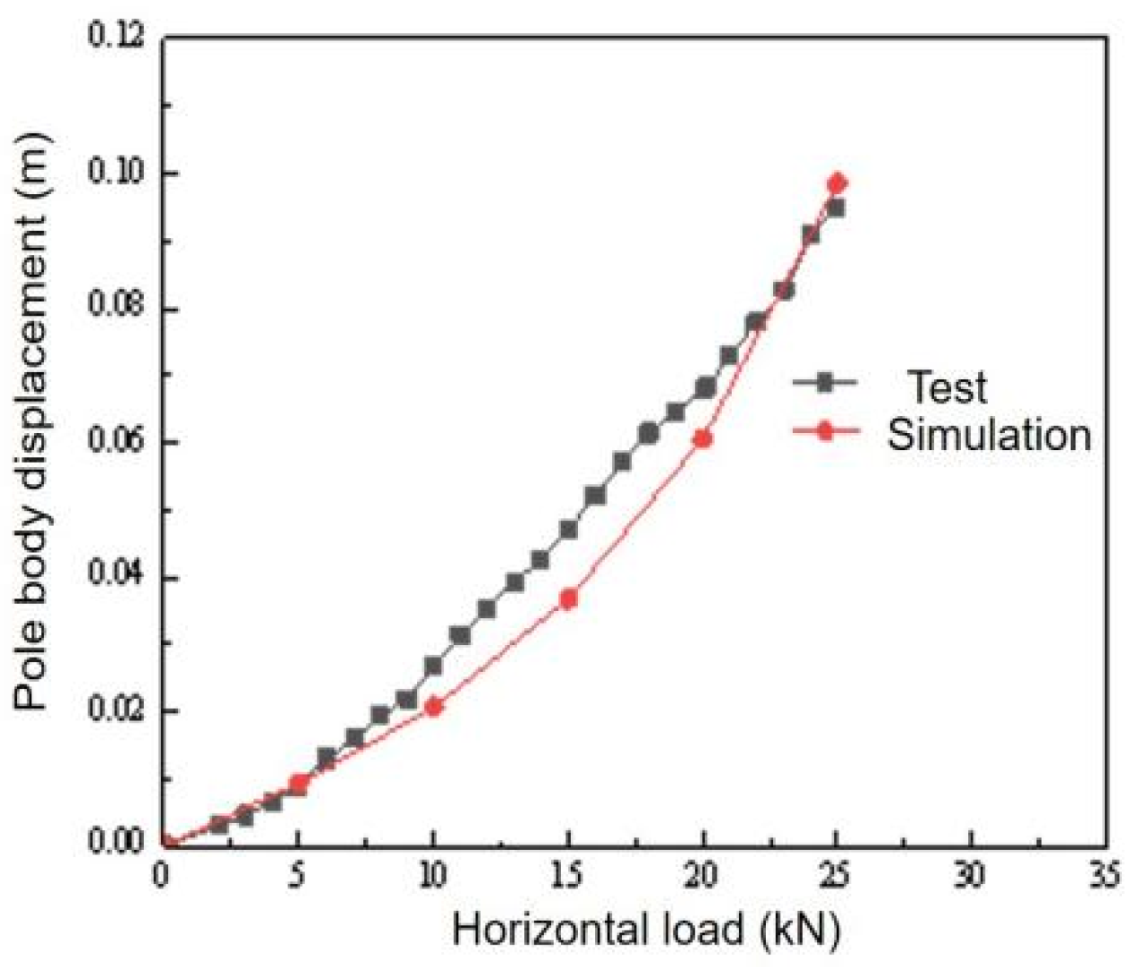
2.2. Model Validation

A comparative analysis is performed between the numerical data and the field test results obtained by our research team to ensure the finite element model’s feasibility. The on-site test adopts the rapid maintenance load method. The reaction force device uses an independent foundation under the concrete column. The loading device is a 10-ton hand chain hoist. The lifting strap is wound around the loading point of the electric pole (2 m above the ground of the pole body). One end of the hand chain hoist is connected to the tensile force sensor and the lifting strap, and the other end is connected to the steel strand anchored to the reaction force device. The test is carried out by loading in equal amounts through force classification. Therefore, the numerical simulation analysis also adopts the force-graded loading method. The force–deformation graph at the loading point is taken as shown in Figure 3. The finite element model results in this study show close agreement with the experimental findings, and, in general, the numerical simulation outcomes match the tendency of the force–displacement curves of field test results. The deformation of the soil around the pole is consistent with the test phenomenon; at about 7 kN, small cracks began to appear between the rear side of the pole and the soil, and the soil on the pressurized side bulged in the later stages of loading. This confirms that it is feasible to analyze the bearing ability of the prefabricated pole base through the calculation of the finite element model. Based on this validation, the effects of foundation dimensions and pile inclination angle on the foundation bearing performance of electric pole prefabricated foundations are further investigated.

3. Influence of Foundation Dimensions on Load-Bearing Performance

3.1. Overview

The modeling is carried out through the method of controlling variables, and the downward pressure-horizontal loading condition is selected, in which the downward pressure load is 25 kN. During the simulation process, factors such as pile inclination angle, pile length and pile diameter are kept unchanged. Among them, the pile inclination angle is set at 10°, the pile length at 1.5 m and the pile diameter at 0.15 m. Four different factors, namely W 0.9, W 1.05, W 1.2 and W 1.35, are simulated to analyze the impact of the foundation size on the prefabricated foundation bearing performance. Among them, W represents the size of the foundation. For example, W 0.9 means the size of the foundation is 0.9 m. The foundation model diagram is illustrated in Figure 4.

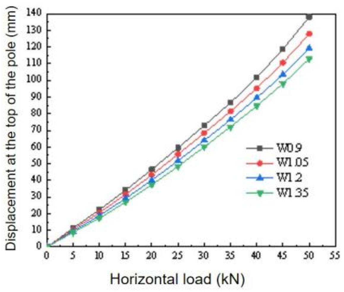
3.2. Lateral Load–Deflection Curve at the Pole Top

Figure 5 illustrates the lateral load–displacement bight of the peak of the pole with a gradually increasing horizontal load step by step when the downward pressure load of 25 kN is applied. And, as is evident from the graph, under the downward pressure-horizontal force, the horizontal displacement at the peak of the pole is enhanced with the growth of the horizontal load under the same foundation dimensions, which shows a nonlinear trend, and the curve is a slow-variation type. The size of the foundation will significantly enhance the foundation bearing ability. The force associated with a 100 mm lateral displacement at the electric pole top relates to the ultimate anti-overturning bearing capacity. The ultimate anti-overturning capacity of the foundation size of 0.9 m is 39.45 kN, and the ultimate anti-overturning capacity of the foundation size of 1.05 m, 1.2 m and 1.35 m is 41.55 kN, 43.76 kN and 45.67 kN, the horizontal bearing capacity increases by 5.32%, 10.90% and 15.77%, respectively, compared with that of 0.9 m. This demonstrates that enlarging the foundation size can effectually improve the anti-overturning load capacity of the foundation. Accordingly, foundation design should consider appropriate size increases. After the size of the foundation increases, the contact surface between the foundation and the soil enlarges, which enhances soil’s suppression of foundation tilt, thereby strengthening the foundation’s anti-overturning bearing ability, further improving the electric pole anti-overturning performance.

3.3. The Lateral Load–Movement Curve of Pile Top Under Different Foundation Dimensions

A downward pressure force of 25 kN is exerted to the peak of the foundation, and the horizontal is applied incrementally. The horizontal force–displacement envelope of the pile apex is shown in Figure 6. The figure demonstrates that the foundation lateral bearing ability is enhanced with the foundation size increase. Regardless of the size of the foundation, the horizontal force–movement graph at the top of the pile exhibits a gradual deformation pattern, reflecting a nonlinear increasing trend, indicating that the foundation has good anti-deformation and bearing capacity. At horizontal loads below 5 kN, the curves corresponding to the four dimensions are approximately the same. When the load exceeds 15 kN, however, the slope differences of the curves gradually become obvious. The slopes from large to small have dimensions 1.35 m < 1.2 m < 1.05 m < 0.9 m in sequence.
The ultimate lateral movement of the pile top reaches 17.5 mm. The ultimate anti-overturning loads corresponding to the foundation piles with dimensions of 1.05 m, 1.2 m and 1.35 m are measured at 44.68 kN, 46.40 kN and 47.74 kN, respectively, representing increases of 4.37%, 8.39%, and 11.52% compared to the 0.9 m foundation. Therefore, when designing the foundation, a moderate enlargement of the foundation dimensions is conducive to improving bearing performance.

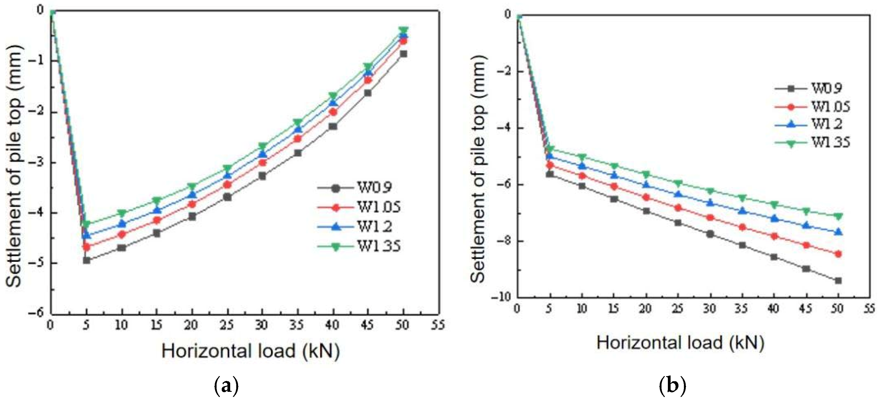
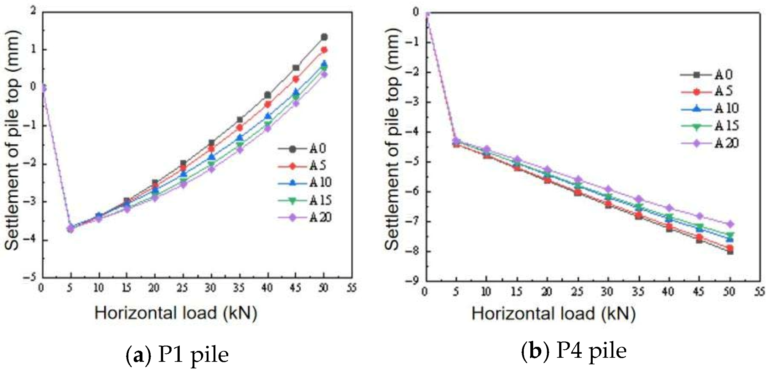
3.4. Settlement Curve of Pile Top Under Different Foundation Dimensions

Figure 7 presents the top settlement variation curves of P1 piles and P4 piles, corresponding to different foundation sizes with gradually increasing horizontal loads when a downward load of 25 kN is applied. The graph illustrates that as the lateral load is less than 5 kN, regardless of the size of the foundation, the settlement curves of P1 piles and P4 piles both show a steep downward trend. This is because the applied lateral force is comparatively minor, and foundation piles mainly bear the impact of the downward load. As the lateral load escalates, the P1 pile of foundation rises and the P4 pile sinks. The cause of this phenomenon is due to the tilt of the foundation under downward pressure and horizontal loads, with the lateral rise in the P1 pile and opposite-side settlement of the P4 pile. Notably, the bigger the foundation size, the lesser the increase or decrease. Consequently, increasing the foundation size can advance the bearing ability of the foundation.
Figure 7a illustrates that as the lateral load is greater than 5 kN and the load increases, the settlement graph of the P1 pile presents an upward tendency. The larger the foundation size, the smaller the corresponding settlement value. For example, as the lateral load grows from 10 kN to 30 kN and the foundation size is 0.9 m, the subsidence of the P1 pile top decreases from 4.68 mm to 3.26 mm, a reduction of 1.42 mm. When the size is 1.35 m, the subsidence of the P1 pile top decreases from 4.00 mm to 2.67 mm, a reduction of 1.33 mm. The reduction compared with the size of 0.9 m decreased by 0.09 mm.
Figure 7b reveals that when the lateral load surpasses 5 kN, the P4 settlement curve maintains a downward trend with increasing load. Similarly, the bigger the foundation size, the lesser the corresponding settlement value. This reason is that in the downward-horizontal load condition, the subsoil beneath the foundation sustains the pressure exerted by the foundation. As the size of the base increases, the contact surface is gradually enhanced. The increase in the contact area disperses the pressure transmitted by the foundation, thereby enhancing the foundation’s vertical bearing ability.

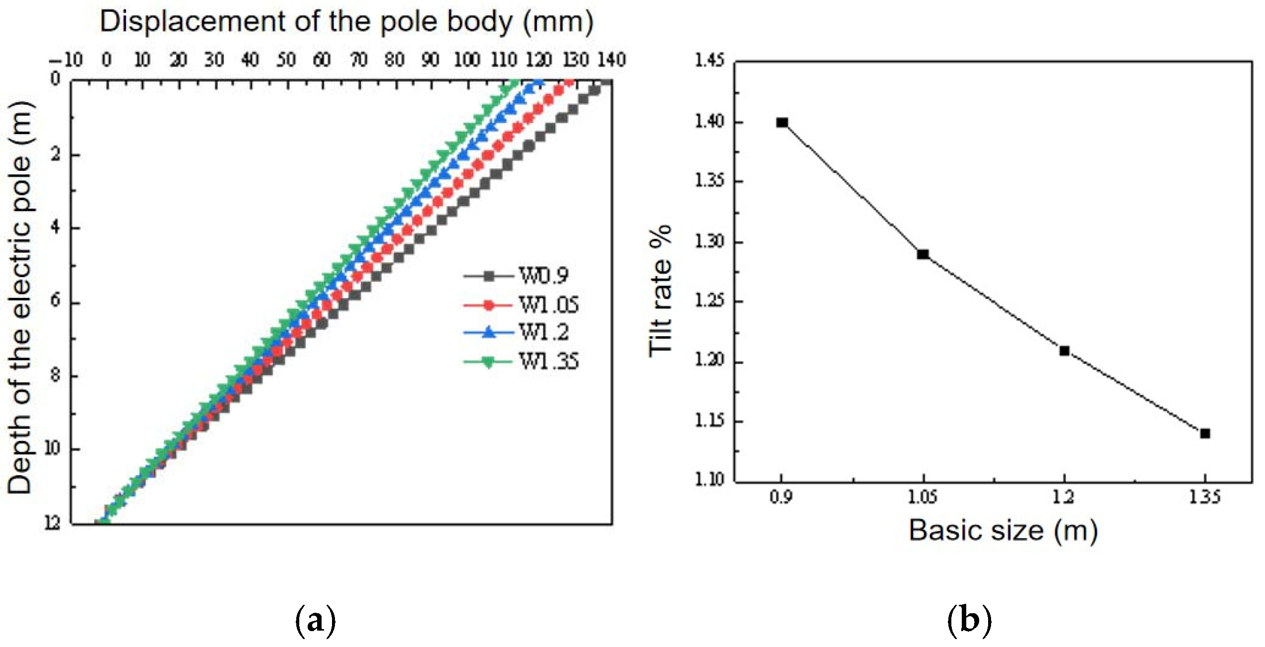
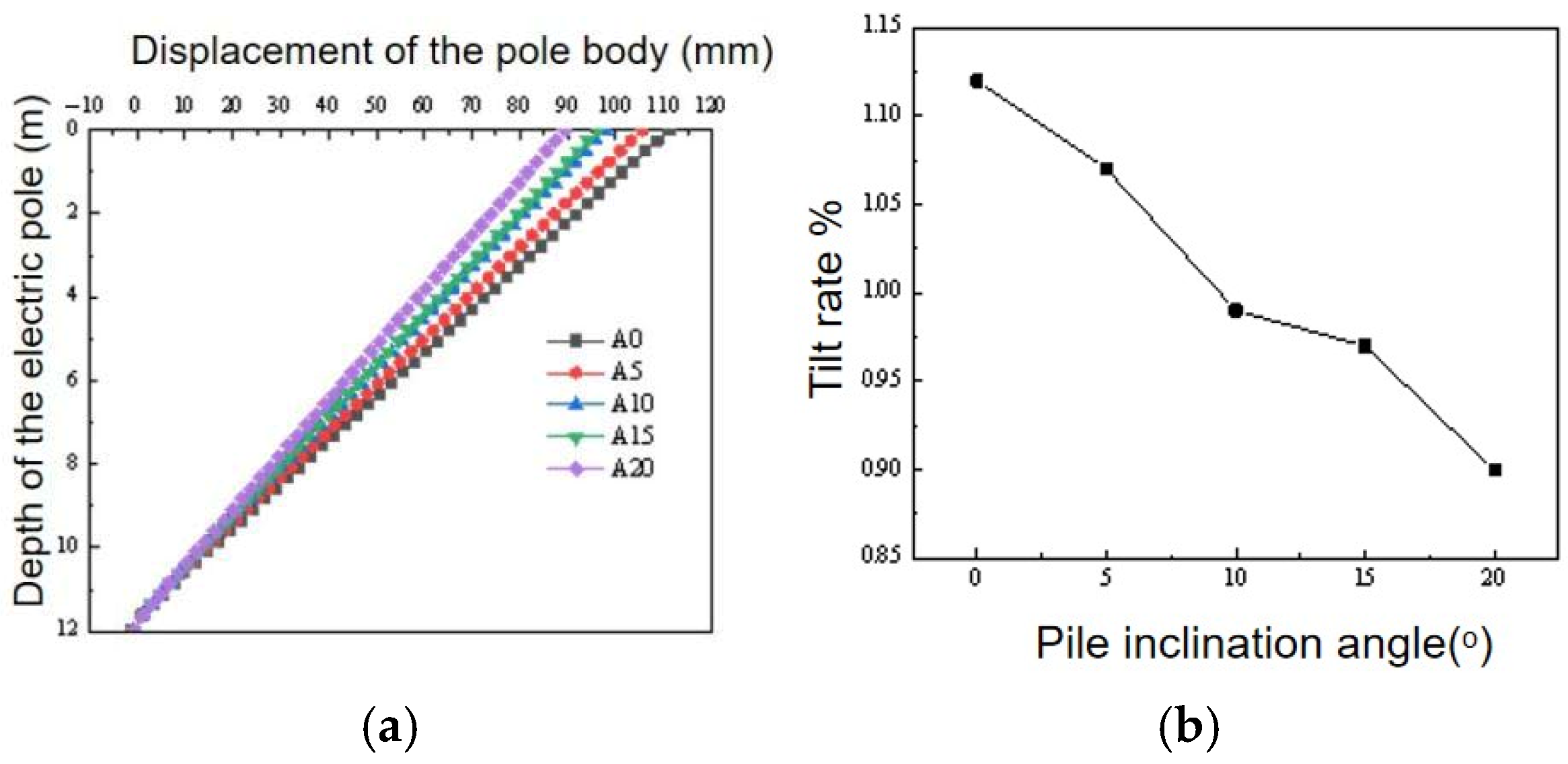
3.5. Displacement and Inclination Rate of the Electric Pole Body

Figure 8a shows the variation curve of the lateral movement of the pole body with the deepness of the pole. The lateral movement of the pole body corresponding to different foundation sizes gradually decreases along the pole. The peak movement of the pole is observed at its apex. At the same pole body position, the bigger the foundation size, the lesser the lateral movement of the pole shaft. For example, at the position of 3 m of the rod shaft, when the foundation dimension is 0.9 m, the pile horizontal movement is 101.79 mm, and when the dimensions are 1.05 m, 1.2 m and 1.35 m, the horizontal displacements of the rod body are 94.37 mm, 88.14 mm and 83.49 mm, respectively. They are reduced by 7.3%, 13.4% and 18.0% compared with the size of 0.9 m.
Figure 8b shows the inclination rate curve of the electric pole. The graph implies that, as the base size increases, the horizontal displacement of the pole body under the same pole depth declines progressively, and the pole inclination rate progressively reduces. The corresponding pole inclination rate is 1.4%, when the base size is 0.9 m; when the dimensions are 1.05 m, 1.2 m and 1.35 m, the pole inclination rates are 1.29%, 1.21% and 1.14%, respectively. They decline by 0.11%, 0.19% and 0.26% relative to 0.9 m. Thus, it is proved that the size of the foundation has an important influence on the bearing performance of the foundation. Enlarging the foundation size can enhance the anti-overturning ability of the electric pole.

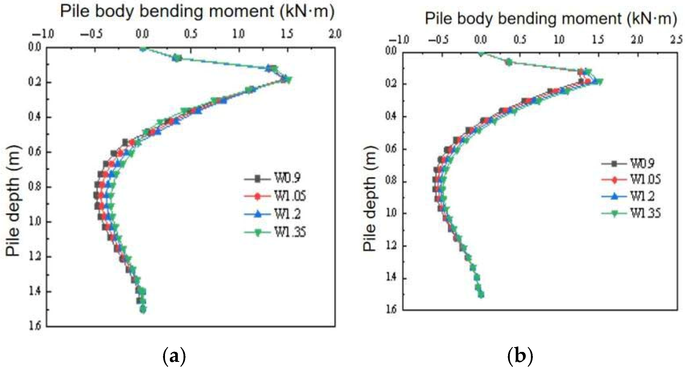
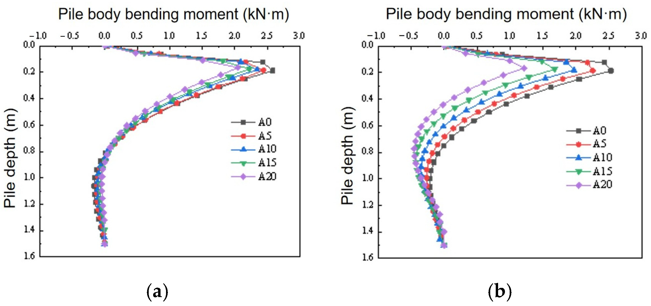
3.6. Pile Body Bending Moment Curve Under Different Foundation Dimensions

The variation in the pile moment along the depth of the pile for inclined piles P1 and P4 in the prefabricated foundation when the downward load is 25 kN is shown in Figure 9. The figure illustrates that whether it is P1 or P4, the pile moment as a whole can be divided into two intervals: The first interval is from the top of the pile to approximately 0.4 m from the pile body. Within this interval, the bending moment of the pile body starts from the top of the pile and increases sharply along the pile depth, reaching the peak bending movement at the position approximately 0.2 m from the pile top. After that, the moment gradually decreases with increasing depth and stops decreasing at a position approximately 0.3–0.4 m, resulting in a reverse bending point. The second interval is from the 0.4 m position to the pile tip. Within this interval, the pile moment gradually grows along the pile depth from the starting position of the interval, attains the peak value of the interval at approximately 0.8 m of the pile shaft, and then gradually diminishes along the pile deepness to nearly zero.
By comparing the bending moments of the pile under diverse foundation sizes, we can see that as the foundation size increases, the corresponding maximum bending movement of the foundation pile body gradually increases. For example, when the foundation size is 0.9 m, the P4 pile peak moment reaches 1.27 kN·m. When the foundation dimensions are 1.05 m, 1.2 m and 1.35 m, the peak bending moments of the pile body are 1.36 kN·m, 1.45 kN·m and 1.52 kN·m, respectively, which increase by 7.1%, 14.2% and 19.7%, respectively, compared with the maximum bending moments when the foundation dimension is 0.9 m.

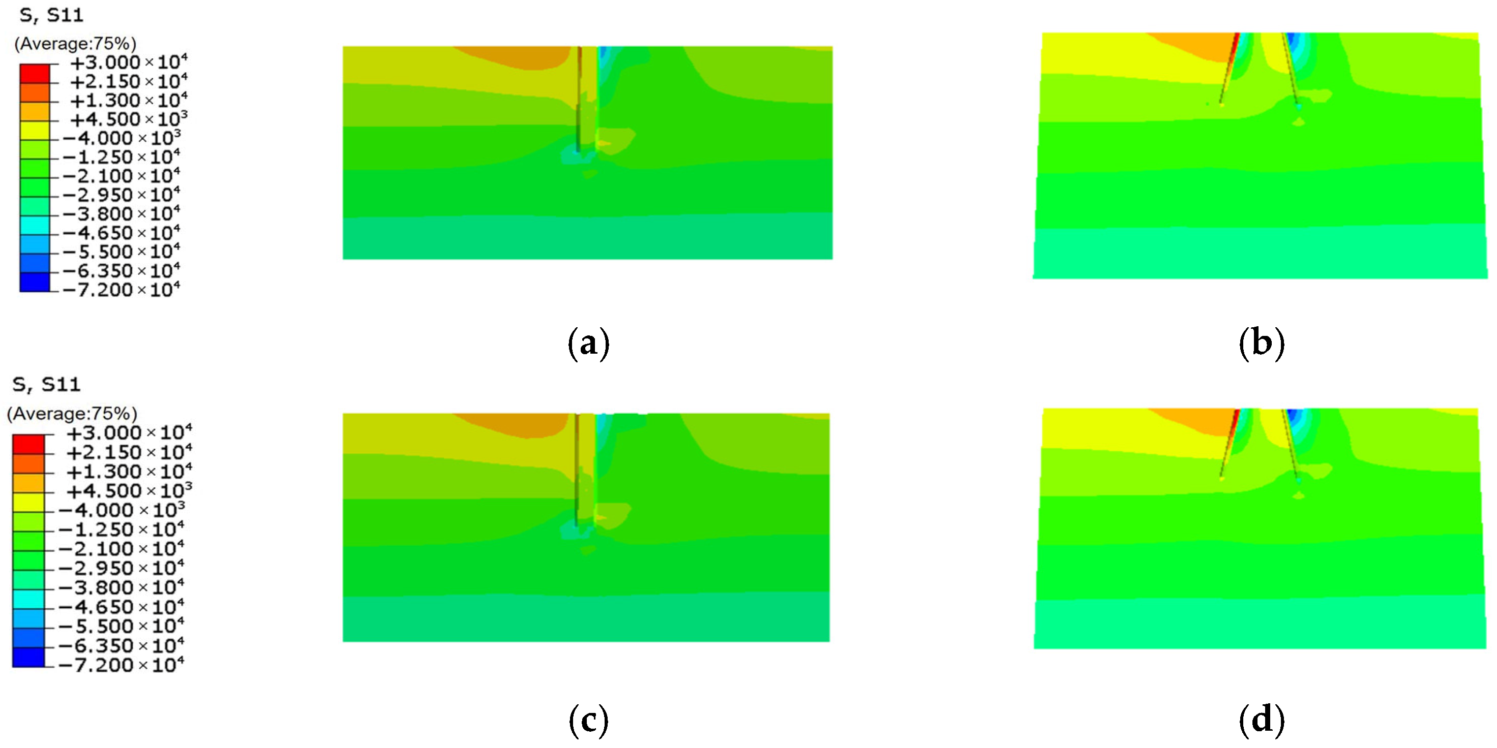
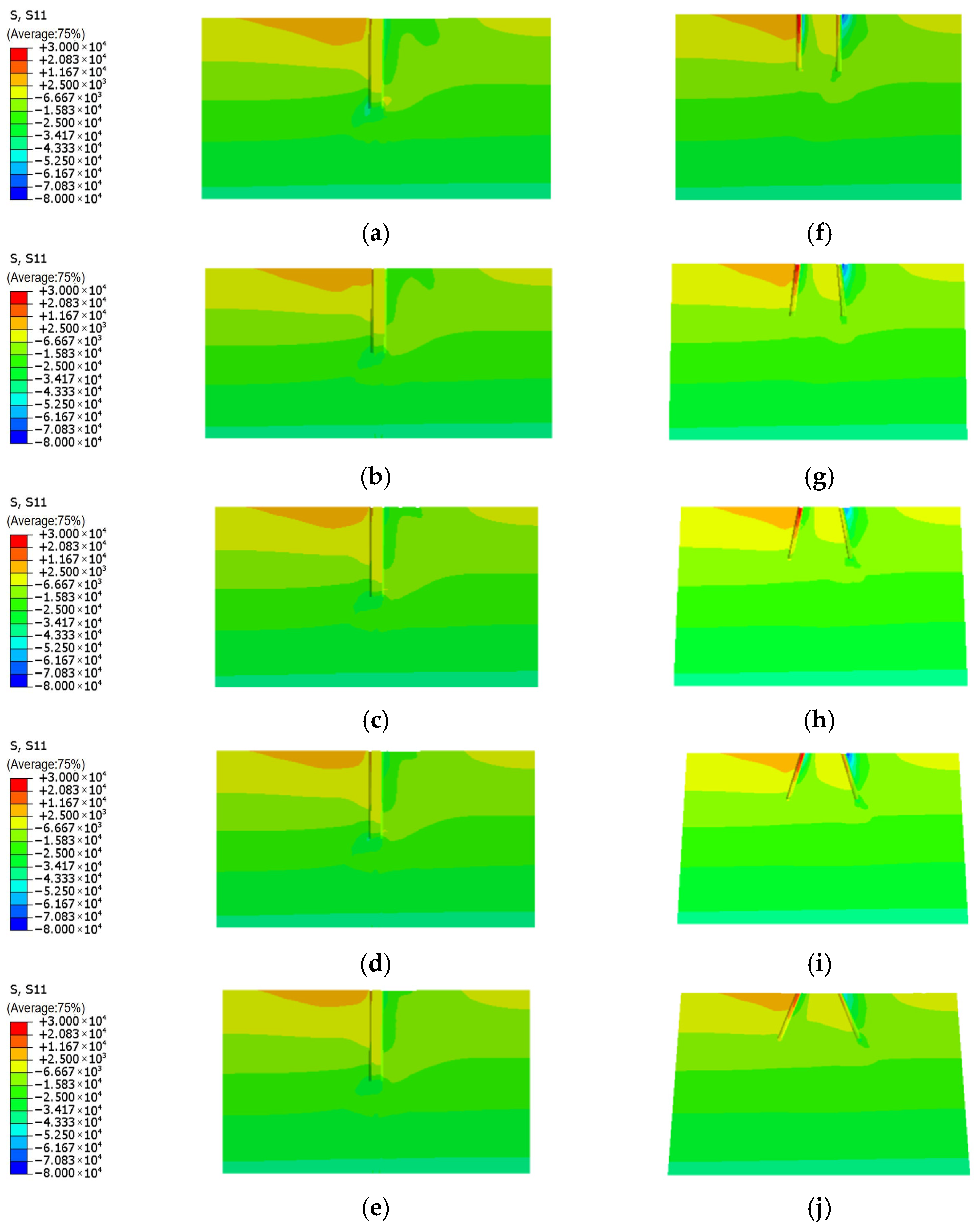
3.7. Analysis of Horizontal Stress Changes in the Soil Around the Foundation

Figure 10 shows a lateral stress cloud map of the subsoil around the foundation (with units in Pa), where a1–a4 are soil stress cloud maps around the poles and b1–b4 are stress cloud maps of the pile’s surrounding soil. As is evident from the graph, the stress-affected zones of soil around the poles of different foundation sizes are approximately the same. The compressive stress of the soil around the pole body is mainly localized at the right side of the pole, and the maximum horizontal stress of the soil arises at the soil surface. The lateral stress around the pole body gradually diminishes as the foundation size increases. The pile body leftward soil is mainly distributed with tensile stress, while that on the right side is compressive stress. As the foundation dimensions expand, the lateral soil stress around the pile shaft diminishes.

4. Impact of Foundation Pile Tilt on Bearing Performance

During the simulation, factors such as the pile diameter and pile length are kept constant. Among them, the pile diameter is set to 0.15 m, the pile length is set to 1.5 m, and the foundation size is 1.35 m. Numerical simulations are conducted on the prefabricated foundations under five different factors, namely A0, A5, A10, A15, and A20. Here, A represents the degree of the pile body inclination angle; for example, A0 indicates that the pile body inclination angle is 0°.

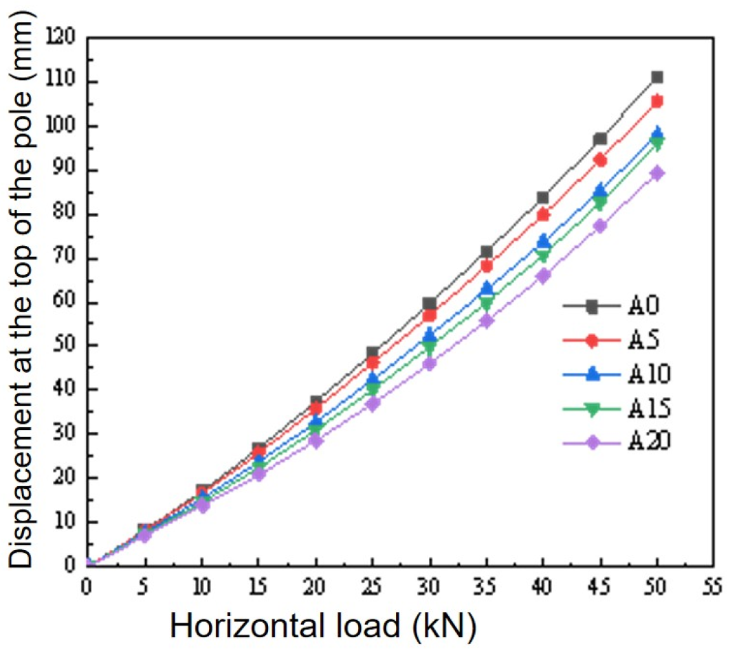
4.1. Horizontal Load–Displacement Graph at the Peak of Electric Pole

Figure 11 shows the lateral load–deformation curve at the peak of the electric pole when a downward pressure force of 25 kN is exerted on the peak of the foundation and horizontal load is applied incrementally. As illustrated in the graph, under identical working conditions, the greater the pile tilt angle, the smaller the corresponding pole lateral movement. The reason for this is that, after the pile inclination angle increases, the foundation inclined piles obtain a larger effective support area than the straight piles, thereby better sharing the load. Moreover, the inclined piles can enhance the lateral resistance of the soil, preventing the foundation from overturning or sliding horizontally. Therefore, the inclined piles can enhance the anti-overturning bearing ability of the foundation.
When the lateral displacement at the peak of the power pole is 85 mm, the corresponding horizontal load is regarded as the ultimate anti-overturning bearing capacity. The ultimate anti-overturning bearing capacity when the pile body inclination angle is 0° is 40.46 kN. When the inclination angles of the pile body are 5°, 10°, 15° and 20°, the ultimate anti-overturning bearing capacities are 42.08 kN, 44.91 kN, 45.91 kN and 48.21 kN, respectively, and the ultimate anti-overturning bearing capacities are increased by 4.0%, 11.0%, 13.5% and 19.2%, respectively, compared with that at 0°.

4.2. The Lateral Load–Movement Curve of Pile Top Under Different Pile Inclination Angles

A downward pressure force of 25 kN is exerted at the peak of the foundation, and the horizontal load is increased step by step. The pile head horizontal load–movement graph is shown in Figure 12. The horizontal displacements of the pile top corresponding to different pile body inclination angles are all of the slow variation, exhibiting a nonlinear rising tendency. When the horizontal force is within the range of 0–10 kN, the movement of the pile peak is not significantly affected by the change in the pile body inclination angle, and the load–displacement curves are approximately the same. When the lateral force exceeds 15 kN, the varying tendency of pile head movement with the pile inclination angle gradually becomes obvious. The greater the load, the greater the difference in the horizontal displacement corresponding to different pile inclination angles.
When the ultimate lateral deformation of the pile head reaches 14 mm and the pile body inclination angle is 0°, the ultimate anti-overturning bearing capacity is 40.97 kN. When the pile body inclination angles are 5°, 10°, 15° and 20°, the ultimate anti-overturning bearing capacities are 42.55 kN, 44.99 kN, 45.71 kN and 47.55 kN, respectively. The ultimate anti-overturning bearing capacity increases by 3.7%, 9.8%, 11.6% and 16.1% compared with that at 0°.

4.3. Settlement Curve of Pile Top Under Different Pile Inclination Angles

The pile head settlement graph when a downward force of 25 kN is exerted to the peak of the foundation and horizontal load is increased step by step in Figure 13. The graph clearly demonstrates that within the horizontal load interval of 0–5 kN, the vertical displacement curves of the pile top show a steep downward trend. This is because the lateral force is comparatively minor, and piles mainly bear the action of the downward load, which leads to the rapid settlement of the piles.
As can be seen from Figure 13a,b, when the horizontal force exceeds 5 kN, the top vertical displacement curve of P1 shows an upward trend, while that of pile P4 shows a downward trend. This is because the foundation tilts under the lateral load, causing one side of the foundation to rise and the other side to sink. Pile P1 is on the rising side, and pile P4 is on the sinking side. Under identical operational conditions, the tilt angle of the P1 foundation pile shows an upward trend, and the rise at the pile top gradually decreases. The P4 inclination angle grows, and the pile head region’s vertical displacement decreases, indicating the vertical foundation force-carrying ability improves. This is because inclined piles can distribute the load to a larger volume of soil, effectively reducing the influence of the foundation’s vertical loading on the subsoil, thereby lowering soil stress and reducing the settlement of the foundation.
For example, for the P4 pile, when the lateral force grows from 5 to 50 kN, the vertical movement corresponding to the 20° inclined pile increases from 4.28 mm to 7.09 mm, and the settlement is 2.81 mm. The vertical displacement corresponding to the 10° inclined pile increases from 4.31 mm to 7.58 mm, and the settlement is 3.27 mm. The settlement amount is 1.16-times that of the 20° pile. When the vertical displacement of the 0° inclined pile rises from 4.41 mm to 8.01 mm, the settlement amount is 3.60 mm, and the settlement amount is 1.28-times that of the 20° pile.

4.4. The Displacement Curve and Inclination Rate of the Electric Pole Body

Figure 14a demonstrates the trend of the lateral displacement of poles varying with deepness. From the curve in the figure, it can be observed that at the same depth, the pole lateral movement corresponding to different inclination angles gradually decreases as the pile tilt angle enhances. For example, at the position of 4 m of the pole body, when the pile tilt angle is 0°, the horizontal movement of the pole body is 72.34 mm, and when the pile inclination angles are 5°, 10°, 15° and 20°, the horizontal displacements of the pole body are 68.75 mm, 63.82 mm, 62.82 mm and 58.44 mm, respectively. They are, respectively, reduced by 5.0%, 11.8%, 13.2% and 19.2% compared with when the pile inclination angle is 0°. Within the range of 0–10 m of the pole body, the differences in the horizontal displacements of the pole body corresponding to different inclination angles are quite obvious. It is clear that as the pile inclination angle grows, the pole lateral movement gradually decreases. Within the range of 10 to 12 m, the lateral deformation of the pole shaft does not vary much under variable operational conditions. This is because this part is buried in the soil, and the foundation is loaded. The compression between the pole and the soil suppresses the lateral deformation of the pole, so the lateral deformation of this part is relatively small.
Figure 14b shows the curve graph of the pole inclination rate varying with the pile inclination angle. With an increase in the pile tilt angle, the inclination rate of the electric pole diminishes progressively. The inclination rates of the electric pole at 5°, 10°, 15° and 20° are 1.07%, 0.99%, 0.97% and 0.9%, respectively, which are reduced by 0.05%, 0.13%, 0.15% and 0.22%, respectively, compared with 0°. Therefore, in the design, it can be considered to change the pile batter angle to improve the load-bearing performance of the foundation, thereby enhancing the anti-overturning ability of the electric poles.

4.5. Pile Body Bending Moment Curve Under Different Pile Inclination Angles

As the lateral force is 25 kN, the trend of the moment of the P1 and P4 inclined piles in the prefabricated foundation along the depth is shown in Figure 15. Both types of piles show a similar pattern, regardless of the tilt angle of the pile shaft. This reaches the maximum value first at the position where the relative pile body’ deepness is about 0.2 m and diminishes with pile depth. A reverse bending point appears at a depth of approximately 0.4 to 0.8 m in the pile shaft and then continues to gradually increase along the pile depth. It grows to maximum and then gradually decreases, approaching zero at the pile base.
The bending moment of the pile body is the greatest at a position 0.2 m below the top of the pile. Under the same working conditions, the inclined pile moment at the same depth is less than that of the straight pile. The maximum bending moment of the P4 pile body with an inclination angle of 0° is 2.59 kN·m. When the pile tilt angle is 5°, 10°, 15° and 20°, the corresponding peak bending moments are 2.44, 2.34, 2.23 and 2.04 kN·m, respectively. They decrease by approximately 5.8%, 9.7%, 13.9% and 21.2%, respectively, compared with that at 0°. Overall, the pile shaft moment of a transmission line using a sloping pile foundation is less than that of a straight pile foundation.

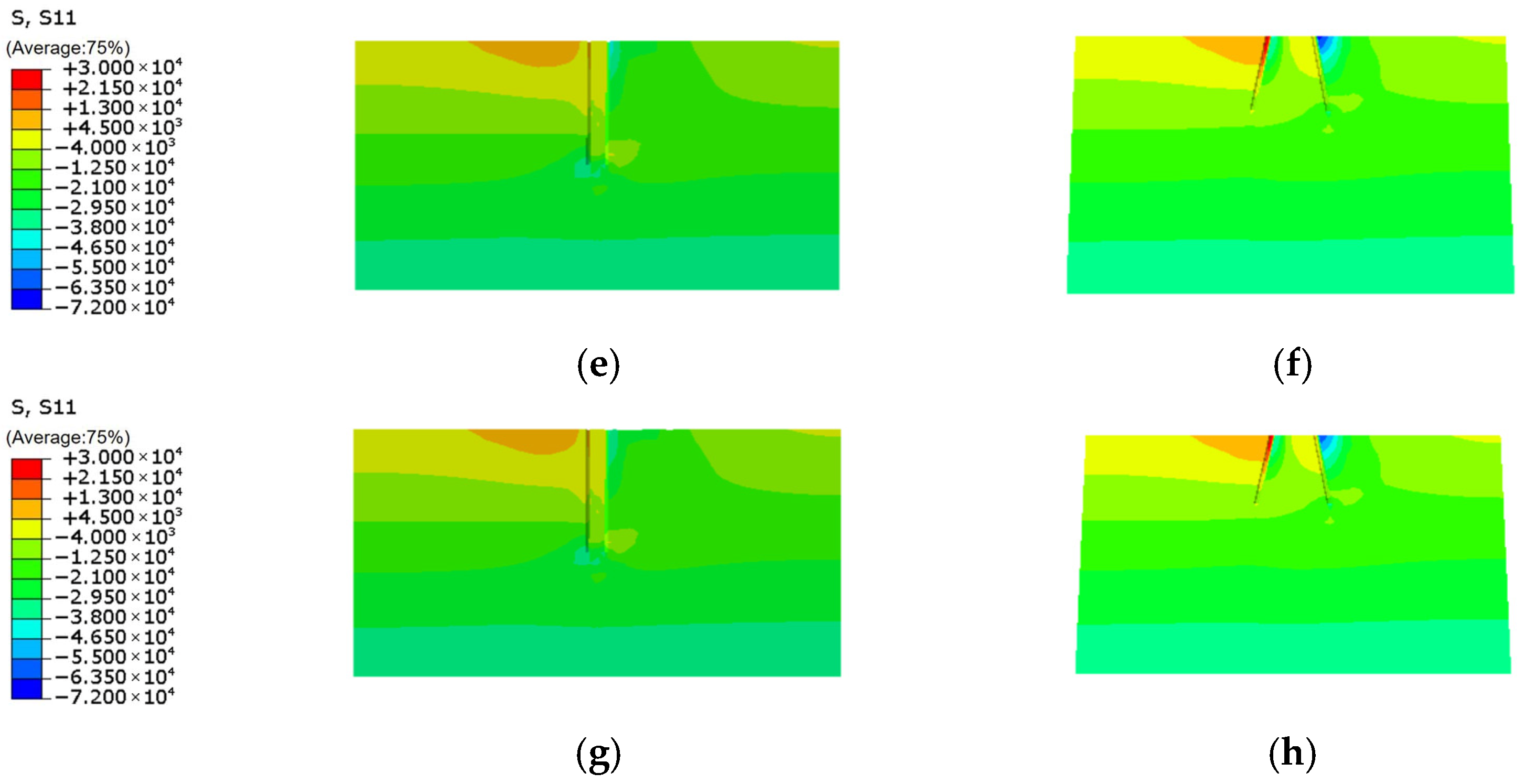
4.6. Analysis of Horizontal Soil Stress Around the Foundation

Figure 16 shows cloud maps of the lateral stress distribution of subsoil around the foundation (with units in Pa). Among them, Figure 16a–e are the lateral stress cloud maps of soil around the pole. Figure 16f–j are cloud maps of the horizontal soil stress around the pile. The compressive stress of the soil around the rod body is mainly concentrated on the right-hand side. The main stress on the right-hand side of the foundation pile body is compressive stress. This is because the foundation undergoes horizontal displacement under load, squeezing the right soil. Tensile stress predominates in pole dextral soil and the pile left lateral side. This is because the foundation and electric pole will tilt after being subjected to horizontal loads, leading to a void between the pole body and the soil on the left side. With the escalation of the foundation pile inclination angle, the horizontal stress of soil around the electric pole gradually decreases, and the range gradually shrinks. The soil stress tendency around the pile body is similar to that of the electric pole, showing that with the escalation of the pile tilt angle, the horizontal stress of soil around P1 piles and P4 piles gradually decreases.

5. Conclusions

In the present study, a 3D finite element model of a prefabricated electric pole foundation is established and validated against field tests to prove the feasibility of the finite element model established in this study. On this basis, by varying the foundation size and pile tilt angle, the subsequent conclusions are drawn:
(1)
The larger the foundation size is, the greater the anti-overturning bearing ability and vertical bearing ability of the prefabricated foundation will be. The ultimate anti-overturning bearing capacities of the foundation sizes of 1.05 m, 1.2 m and 1.35 m increased by 5.32%, 10.90% and 15.77%, respectively, compared with those of the size of 0.9 m. Additionally, the lateral movement and inclination rate of the pole body decreased.
(2)
The bigger the pile inclination angle, the more excellent the anti-overturning bearing capacity and prefabricated foundation vertical bearing ability. The ultimate anti-overturning bearing ability at pile body inclinations of 5°, 10°, 15° and 20° increased by 4.0%, 11.0%, 13.5% and 19.2%, respectively, compared with 0°, and the lateral movement and pole inclination rate decreased. As the pile inclination angle increases, the foundation pile body’s maximum bending moment shows a decline. The largest moment arises at position 0.2 m of the pile shaft. Although increasing the pile inclination angle can enhance the bearing capacity of the foundation, an excessively large inclination angle is not conducive to the control of construction quality. It is recommended that the pile body inclination angle be controlled within 10° in engineering design.
This study studies the foundation bearing deformation characteristics under downward pressure and lateral load through numerical simulation methods and explores the behavior when inclined piles are used in prefabricated foundations. However, this study also has certain limitations. The suggestions for further research on prefabricated inclined pile foundations are as follows:
(1)
In actual engineering, the geological conditions are complex. We only select a single set of soil parameters, and the bearing performance of the prefabricated inclined pile foundation analyzed is also carried out under the soil parameters selected in this study. Therefore, it is suggested to analyze the bearing ability of prefabricated inclined pile foundations under different geological conditions.
(2)
This study only analyzes the bearing ability of the foundation under downward pressure-horizontal conditions and does not analyze the bearing performance of the foundation under upward pull-horizontal conditions.
(3)
Field tests are the most intuitive way to evaluate the bearing performance of prefabricated foundations. Therefore, it is recommended to conduct field tests to study the bearing performance of prefabricated foundations when inclined piles are applied.

Author Contributions

C.Z.: methodology and writing—review and editing; W.S.: formal analysis, writing—original draft; W.H.: data curation, methodology; F.G.: project administration, writing—review and editing.; Y.Y.: investigation, writing—original draft; M.K.: conceptualization, supervision, writing—original draft; L.Z.: investigation; Y.W.: investigation. All authors have read and agreed to the published version of the manuscript.

Funding

This research is funded by the Economic and Technical Research Institute of State Grid Henan Electric Power Co. State Grid Corporation of China technology project. (No. SGHAYJ00SJJS2400038).

Data Availability Statement

Data associated with the present study will be available upon request from the corresponding authors.

Acknowledgments

This research was supported by a grant from the Economic and Technical Research Institute of State Grid Henan Electric Power Co.

Conflicts of Interest

Authors Chong Zhao, Wenzhuo Song, Furan Guo and Liang Zhang were employed by the company Economic and Technical Research Institute of State Grid Henan Electric Power Co. The remaining authors declare that the research was conducted in the absence of any commercial or financial relationships that could be construed as a potential conflict of interest.

References

  1. Hu, J.-Y.; Liu, M.-H. Analysis of Overhead Optical Cable Installation Methods. Heilongjiang Sci. Technol. Inf. 2010, 16, 47+184. [Google Scholar]
  2. Ye, J.-B.; Wang, C.-F.; Huang, W.-P.; Zhang, J.; Zhou, X. Effect of inclination angle on the response of double-row retaining piles: Experimental and numerical investigation. Teh. Vjesn. 2020, 27, 1150–1159. [Google Scholar]
  3. Wang, D.; Ju, Y.-Z.; Ju, M.-S.; Song, M.; Zhao, J.; Bai, J. Uplift Bearing Capacity of Squeezed Branch Pile Group. Geotech. Geol. Eng. 2022, 41, 283–293. [Google Scholar] [CrossRef]
  4. Wang, D.-H.; Ju, Y.-Z.; Zhao, X.-P.; Bai, J.-F. Field test and numerical simulation on bearing capacity of squeezed branch pile in Transmission line. Mechanics 2017, 23, 762–768. [Google Scholar]
  5. Huang, W.-H.; Zhou, Z.-Y.; Zhang, C.-T.; Qiu, H.-S. Numerical Analysis of Bearing Behavior for Inclined-Vertical Pile Groups in Coastal Terrestrial Zones. Eng. Constr. 2021, 35, 301–306. [Google Scholar]
  6. Li, L.-Q.; Zhao, H.-Q. Analysis of Lateral Bearing Behavior for Inclined Pile Foundations Under Combined Loading. Eng. Sci. Technol. 2022, 54, 124–134. [Google Scholar]
  7. Fan, W.-F.; Xu, Y.-Q. Numerical Analysis of Bearing Behavior for Inclined Pile Foundations in Transmission Tower Bases Under Horizontal Loading. Ground Treat. 2023, 5, 492–497. [Google Scholar]
  8. Song, Y.-G.; Wang, J.-K. Numerical Simulation-Based Analysis of Horizontal and Vertical Bearing Behavior in Inclined Pile Groups. J. Lanzhou Univ. Technol. 2023, 49, 142–149. [Google Scholar]
  9. Liu, C.; Yan, C.-D.; Zheng, G.; Liu, T.; Yang, Y. Field Testing and Numerical Analysis of Supporting Performance of Oblique Piles Used in Pit Excavation. Int. J. Geomech. 2023, 23, 04023204. [Google Scholar] [CrossRef]
  10. Zhao, S.; Wu, J.-T.; Wu, W.-B.; Wen, M.; Wang, K.; Faheem, R.S.M. Bearing behaviors and design method of laterally loaded batter pile groups (BPGs) in sand. Ocean Eng. 2023, 287, 115685. [Google Scholar] [CrossRef]
  11. Zhao, S.; Wang, K.-H.; Wu, J.-T.; Chen, W.; Tu, Y. Investigation of the vertical responses of 2 × 2 square flexible batter pile groups in sand. Mar. Geores. Geotechnol. 2023, 41, 751–763. [Google Scholar] [CrossRef]
  12. Liu, C.; Zhang, B.-J.; Miao, P.; Yan, C.-D. Model test and stress mechanism study of horizontally loaded inclined pile group. J. Tianjin Univ. (Nat. Sci. Technol.) 2023, 56, 275–288. [Google Scholar]
  13. Zhang, L.; Shen, J.-H.; Chen, C.; Luo, D. Lateral bearing characteristics of inclined pile-cap system installed in sandy ground. Chin. J. Geotech. 2024, 46, 120–130. [Google Scholar]
  14. Fan, W.-F.; Cao, W.-P. Numerical Analysis of Lateral Bearing-Deformation Behavior in Capped Inclined Single Piles. J. Chang. River Sci. Res. Inst. 2016, 33, 121–125. [Google Scholar]
  15. Aminfar, A.; Ahmadi, H.; Aminfar, H.M. Parametric study on the effects of pile inclination angleon the response of batter piles in offshore jacket platforms. J. Mar. Sci. Appl. 2016, 15, 193–200. [Google Scholar] [CrossRef]
  16. Zhang, W.; Zhang, X.-L.; Zhang, Z.-H.; Wei, H.-W. Field test study and numerical analysis of the horizontal bearing characteristics of pile groups. Geotech. Investig. Surv. 2023, 51, 19–28. [Google Scholar]
  17. Wu, K.-H. Numerical simulation study on the influence of inclined pile arrangement on the bearing capacity of micro pile groups. Fujian Constr. Sci. Technol. 2015, 2, 4–7. [Google Scholar]
  18. Asgari, A.; Bagheri, M.; Hadizadeh, M. Advanced seismic analysis of soil-foundation-structure interaction for shallow and pile foundations in saturated and dry deposits: Insights from 3D parallel finite element modeling. Structures 2024, 69, 107503. [Google Scholar] [CrossRef]
  19. Bagheri, M.; Jamkhaneh, M.E.; Samali, B. Effect of seismic soil–pile–structure interaction on mid-and high-rise steel buildings resting on a group of pile foundations. Int. J. Geomech. 2018, 18, 04018103. [Google Scholar] [CrossRef]
  20. Çetindemir, O. Nonlinear constitutive soil models for the soil–structure interaction modeling issues with emphasis on shallow tunnels: A review. Arab. J. Sci. Eng. 2023, 48, 12657–12691. [Google Scholar] [CrossRef]
  21. Ju, Y.; Zhang, H.; Wang, D.; Kong, X.; Ma, Y.; Zhang, X.; Bai, J. Effect of mineral admixtures on the resistance to sulfate attack of reactive powder concrete. J. Clean. Prod. 2024, 440, 140769. [Google Scholar] [CrossRef]
  22. Wang, D.; Ma, Y.; Kang, M.; Ju, Y.; Zeng, C. Durability of reactive powder concrete containing mineral admixtures in seawater erosion environment. Constr. Build. Mater. 2021, 306, 124863. [Google Scholar] [CrossRef]
  23. Ju, Y.-Z.; Shen, T.; Wang, D. Bonding behavior between reactive powder concrete and normal strength concrete. Constr. Build. Mater. 2020, 242, 118024. [Google Scholar] [CrossRef]
  24. Jian, W.-B.; Wu, Z.-X.; Liu, H.-M.; Chen, Z.; Zhang, M. Cone penetration parameters of soil in coastal areas of Fujian. Chin. J. Rock Mech. Eng. 2004, S1, 4414–4417. [Google Scholar]
Figure 1. Design drawings of prefabricated foundation.
Buildings 15 02656 g001
Figure 2. Picture of the numerical model.
Buildings 15 02656 g002
Figure 3. Comparison of finite element analysis and field tests.
Buildings 15 02656 g003
Figure 4. Diagram of the base model.
Buildings 15 02656 g004
Figure 5. Force–displacement envelope of the pole apex.
Buildings 15 02656 g005
Figure 6. Horizontal force–displacement envelope of pile apex.
Buildings 15 02656 g006
Figure 7. Pile head vertical displacement curve: (a) P1 pile head vertical displacement curve; (b) P4 pile top settlement curve.
Buildings 15 02656 g007
Figure 8. Displacement curve and inclination of pole shaft: (a) movement curve of pole shaft; (b) pole tilt rate.
Buildings 15 02656 g008
Figure 9. Pile moment curve under different foundation dimensions: (a) P1 pile moment curve; (b) P4 pile moment curve.
Buildings 15 02656 g009
Figure 10. Horizontal stress cloud diagram of soil around foundation: (a) a1 pole; (b) b1 pile; (c) a2 pole; (d) b2 pile; (e) a3 pole; (f) b3 pile; (g) a4 pole; (h) b4 pile.
Buildings 15 02656 g010aBuildings 15 02656 g010b
Figure 11. Load–displacement curve at the peak of the pole.
Buildings 15 02656 g011
Figure 12. Pile head horizontal load–movement graph.
Buildings 15 02656 g012
Figure 13. Pile top settlement curves.
Buildings 15 02656 g013
Figure 14. Displacement curve and inclination of the pole shaft: (a) displacement curve of the pole body; (b) pole tilt rate.
Buildings 15 02656 g014
Figure 15. Pile moment curve under different pile inclination angles: (a) P1 pile moment curve; (b) P4 pile moment curve.
Buildings 15 02656 g015
Figure 16. Horizontal stress cloud graph of soil around foundation: (a) a1 pole; (b) a2 pole; (c) a3 pole; (d) a4 pole; (e) a5 pole; (f) b1 pile; (g) b2 pile; (h) b3 pile; (i) b4 pile; (j) b5 pile.
Buildings 15 02656 g016
Table 1. Soil properties.
TypeDensityElastic Modulus/(MPa)Poisson RatioAngle of Friction (°)Cohesion (kPa)
Soil layer 118303.80.32112
Soil layer 2195070.32715
Disclaimer/Publisher’s Note: The statements, opinions and data contained in all publications are solely those of the individual author(s) and contributor(s) and not of MDPI and/or the editor(s). MDPI and/or the editor(s) disclaim responsibility for any injury to people or property resulting from any ideas, methods, instructions or products referred to in the content.

