Article

Anti-Overturning Performance of Prefabricated Foundations for Distribution Line Poles

1
Economic and Technical Research Institute, State Grid Henan Electric Power Co., Ltd., Zhengzhou 450052, China
2
School of Civil Engineering and Architecture, Northeast Electric Power University, Jilin 132012, China
*
Author to whom correspondence should be addressed.
Buildings 2025, 15(15), 2717; https://doi.org/10.3390/buildings15152717
Submission received: 10 June 2025 / Revised: 20 July 2025 / Accepted: 28 July 2025 / Published: 1 August 2025

Abstract

To enhance the anti-overturning performance of poles and prevent tilting or collapse, a prefabricated foundation for distribution lines is developed. Field tests are conducted on five groups of foundations. Based on the test results, finite element analysis (FEA) is employed to investigate the influence of different factors—such as pole embedment depth, foundation locations, soil type, and soil parameters—on the anti-overturning performance of pole prefabricated foundations. The results indicate that under ultimate load conditions, the reaction force distribution at the base of the foundation approximates a triangular pattern, and the lateral earth pressure on the pole follows an approximately quadratic parabolic distribution along the depth. When the foundation size increases from 0.8 m to 0.9 m, the bearing capacity of the prefabricated foundation improves by 8%. Furthermore, when the load direction changes from 0° to 45°, the foundation’s bearing capacity increases by 14%. When the foundation is buried at a depth of 1.0 m, compared with the ground position, the ultimate overturning moment of the prefabricated foundation increases by 10%. Based on field test results, finite element simulation results, and limit equilibrium theory, a calculation method for the anti-overturning bearing capacity of prefabricated pole foundations is developed, which can provide a practical reference for the engineering design of distribution line poles and their prefabricated foundations.

1. Introduction

In recent years, long-term operation of distribution lines has resulted in pole tilting due to strong winds and uneven foundation settlement [1]. Under extreme weather conditions, such as typhoons, these poles may experience further tilting or even collapse, jeopardizing the reliability of power distribution networks (see Table 1).
Li and Zhang [2,3] summarized the research status of prefabricated foundations in the electric power industry, and outlined the common prefabricated foundation forms and application scope in this industry. Rasmussen [4] designed a prefabricated bar foundation made of EPS (expandable polystyrene) plastic as raw material, and a prefabricated foundation unit could be flexibly assembled into a bar foundation of different shapes. Brown [5] designed a tower foundation consisting of a foundation plate, pillar plates, and a top plate, secured by threaded nuts within six steel conduits. Zhu [6] studied the position of the overturning point of the foundation under horizontal load and explored the influence of the position on the anti-overturning bearing capacity of the foundation. Haldar and McNames [7,8] conducted on-site performance tests and studies on steel pipe rods and tower foundations. Li [9] proposed a new type of prefabricated foundation for onshore wind power. Through theoretical calculation and finite element analysis, the mechanical and load-bearing mechanism of the new foundation was explored. Batali [10] compared the finite element numerical results of an isolated pile foundation in sandy soil under the action of wave or wind circulation with test results. Li [11] proposed a prefabricated foundation of 66 kV transmission line poles and towers, and used Solidworks to simulate and analyze the mechanical properties of the foundation. Ghalesari [12] adopted the three-dimensional finite element method and considered the complete interaction between the components of a pile–raft foundation to conduct parametric research. Wang [13] studied the tensile and compressive properties of a barrel foundation considering the aspect ratio (AP), and found that the ultimate bearing capacity of the barrel foundation significantly increased with the increase in the AP. Wang [14] considered lateral soil pressure as a favorable influence on a short column foundation, calculated the horizontal force and overturning moment acting on the top of the short column, the base reaction and overturning moment and shear generated on the short column foundation, and the vertical load reaction on the foundation of the short column foundation. Nogueira [15] proposed a self-stabilized prefabricated foundation. The foundation base consisted of three reinforced-concrete prefabricated parts assembled by bolts; the shaped steel bracket and the base were assembled, and finally weights of equal mass were placed on the shaped steel on both sides of the tower. Zhou [16] obtained analytical formulas for ultimate bearing capacity and N when the foundation is completely smooth based on the limit equilibrium theory and the unified strength theory. Mo [17] combined the Mohr–Coulomb strength theory with the slip line field theory, and proposed a theory to describe the relationship between internal friction angle, cohesion, lateral pressure, and critical load. Zhang et al. [18,19,20] conducted a series of studies on the construction of grading equations based on fractal theory for coarse-grained roadbed fill (CSF), the disintegration characteristics of red-layered soft rock as roadbed fill, and the grading limits of gangue roadbed fill (CGSF), which provided theoretical support for the stability and safety of roadbeds and related infrastructure structures. Ahmad, Nasir, and Rawat [21,22,23] studied the mechanical and axial properties of concrete containing recycled plastic coarse aggregate (RPAC) reinforced with silica fume and steel fibers, and the refractory and thermal properties of magnesium oxychloride cementitious composites (HFMOC), which provide references for environmentally friendly material applications in structures such as building foundations. Raza et al. [24] evaluated 210 buildings using the FEMA P-154 rapid visual screening method and found that most had problems with planar and vertical irregularities, which underscored the need to upgrade buildings and foundations for seismic resistance. Ju and Wang et al. [25,26] explored the influence of mineral admixtures in foundation engineering on the sulfate resistance of active powder concrete and the mechanical properties of high-performance concrete reinforced with basalt fiber and polypropylene fiber.
Current research focuses primarily on prefabricated foundations for transmission lines, with significantly less attention paid to distribution line applications. Distribution line foundations face particular challenges in anti-overturning capacity due to prolonged exposure to strong winds, uneven settlement, and other complex environmental factors. Traditional power pole chuck bases further complicate construction due to their bulk and weight. Therefore, it is necessary to carry out research on the method of improving the load-bearing capacity of distribution line pole prefabricated foundations.
To address this need, a prefabricated foundation for distribution lines is developed. In order to study the bearing capacity of the pole prefabricated foundation, on-site prototype tests and numerical simulation analysis are conducted. The load direction, foundation size, clamp height, pole embedment depth, foundation position, soil types, and soil parameters are changed to study the distribution of lateral soil pressure on electric poles, the distribution of base reaction force on prefabricated foundations, and the ultimate bearing capacity. Finally, based on the field tests and finite element simulation analysis, an ultimate bearing capacity calculation method of the prefabricated foundation of an electric pole is proposed, which provides a theoretical basis for the design of electric poles and their prefabricated foundations against overturning.

2. Prototype Test

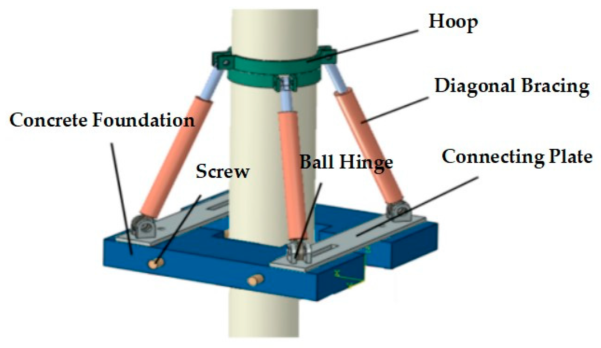
2.1. Prefabricated Foundation Composition

The prefabricated foundation is composed of two precast concrete foundations, four diagonal braces, two connecting plates with ball joints, two pairs of hoops, and two screws, with all parts bolted together, providing modularity and mechanization, as shown in Figure 1. The connection between the pole and the prefabricated foundation is realized through four diagonal braces and two pairs of hoops. The ball hinge can be rotated 360°, and the four diagonal braces can be arbitrarily adjusted in the horizontal direction. The precast concrete foundation uses screws for firm connections. The flowchart is shown in Figure 2.

2.2. Experimental Design

In order to study the anti-overturning performance of the prefabricated foundations of the poles, five groups of foundations are designed. In practice, pole foundations may be subjected to multi-directional loads (e.g., wind loads, wire tension). According to GB 50061-2010 “Design Standard for Overhead Power Lines of 66 kV and Below” [27], when calculating the wind load on poles and towers, four possible wind directions of 0°, 45°, 60°, and 90° should be taken into account. For straight poles and towers, the basic wind speeds of 0°, 45° (or 60°), and 90° should be calculated. Therefore, two loading directions are selected in the study, 0° to simulate forces aligned with the geometric axis of symmetry of the foundation, and 45° to simulate the foundation being subjected to diagonal complex loads. Since greater hoop height enhances pole constraint and reduces bottom deformation, two heights were selected based on the economic and load-carrying capacity requirements. The specific test foundation types and loading conditions are shown in Table 2. The soil parameters are shown in Table 3. The loading direction is shown in Figure 3. The aim of the field test is to obtain the load-bearing capacity of the prefabricated foundation of the pole through a field true-type test under the conditions of downward pressure and horizontal coupling. The factors of foundation type and loading conditions are considered in the test. The burial depth of all the electric poles is 2.5 m, and the burial depth of the foundation is 0.5 m. The foundation adopts C50 concrete.

2.3. Test Loading Device and Measurement Method

The test is based on the common step spacing and pole height, as well as the common ratio of horizontal load to vertical load. According to the overturning moment generated on the poles under the wind load [28] of the distribution network lines in Fujian Province, a concentrated load is applied to approximate the overturning moment on the poles. The test loading point is 3 m from the ground, and considering the relationship between the horizontal load of the pole and the self-weight of the poles and their upper subsidiary components under actual working conditions, the angle between the loading direction and the pole is selected to be 45°. The test adopts a graded loading mode, in which the load of each stage is 1/10 of the estimated load according to the actual working conditions. When the load of each stage remains stable for a period of time, the data is recorded. After the end of each stage of loading, wait until the pole loading point displacement is stable before the next stage of loading. According to DL/T741-2019 ‘Regulations for the Operation of Overhead Transmission Lines” [29], the loading termination condition is that the pole inclination angle reaches 0.015 rad, and the ultimate load value is the corresponding load value at the end of loading. The site loading diagram is shown in Figure 4.
The top load of the rod is measured by the tension sensor, and the measurement range of the tension sensor is based on its 30 kN capacity. The displacement of the rod top is measured by a pull wire displacement sensor. The force sensor and pull-displacement meter are connected to the MP-10 type pole load deflection tester produced by Shanghai Dongzi Electronic Technology Development Co., Ltd. in Shanghai, China. Moreover, 0–0.1 MPa soil pressure boxes are arranged symmetrically at the bottom of the prefabricated foundation to measure the base reaction; Seven soil pressure boxes with pressure ranging from 0 to 0.3 MPa are selected to measure the lateral soil pressure of the pole, and are arranged on the front side of the pole at 0.2 m, 0.5 m, 1 m, and 1.5 m, and on the rear side at 2.0 m, 2.2 m, and 2.5 m, respectively. The soil pressure boxes collect and record data through the DH3818Y acquisition instrument produced by Donghua Testing Company in Taizhou, China. The layout of the soil pressure boxes is shown in Figure 5 and Figure 6.

2.4. Test Observations

The test phenomena in the five groups of experiments are similar, taking specimen SJ-1 as an example. The loading direction is 0°. The prefabricated foundation is 800 × 800 mm in size, and the hoop is 3.3 m in height. The description of the test phenomena is provided in Table 4, and the cracks in the soil around the pole are shown in Figure 7.

2.5. Test Results and Analysis

2.5.1. Overturning Moment–Rotation Angle

The overturning moment–rotation curves for SJ-1 to SJ-5 are shown in Figure 8. SJ-1 reaches 0.015 rad when the load reaches 14.21 kN, and the overturning moment of the pole is 30.15 kN·m; SJ-2 reaches 0.015 rad when the load reaches 16.20 kN, and the overturning moment of the pole is calculated to be 34.37 kN·m. Compared with SJ-1, the bearing capacity of SJ-2 is increased by 14% under different loading directions. SJ-3 reaches 0.015 rad when the load reaches 17.47 kN, and the overturning moment of the pole is calculated to be 37.05 kN·m. In a comparison with test specimen SJ-2, the base size of SJ-3 is increased from 0.8 m to 0.9 m, and the bearing capacity of SJ-3 is increased by 8%. SJ-4 reaches 0.015 rad when the load reaches 13.93 kN, and the overturning moment of the pole is calculated to be 29.56 kN·m. In a comparison of samples SJ-1 and SJ-4, we find that the influence of changing the hoop position on their ultimate overturning moment is limited.

2.5.2. Base Reaction of Fabricated Foundation

The locations of the measurement points are shown in Figure 4. The front side of the pole is defined as measurement point 1 and the rear side is defined as measurement point 2 when the loading direction is 0°; measurement point 3 is defined as the point perpendicular to the loading direction when the loading direction is 45°. In the initial state, the soil pressures at the basement measurement points are approximately equal. At a loading direction of 0°, the basement soil pressure at measuring point 2 gradually decreases with the increase in the load value. When the limit state is not reached, the soil pressure of the basement at measuring point 2 drops to 0, indicating that the prefabricated foundation has been separated from the soil at this time; at measuring point 1, the base soil pressure increases step by step with the load, and the increment in soil pressure is approximately linear; and when the loading direction of measuring point 3 is 45°, the basement soil pressure increases, indicating that measuring point 3 is not separated from the soil and is still under pressure, and the growth trend is approximately linear. Substrate soil pressure curves with different loading directions are shown in Figure 9.
Substrate soil pressure curves for different foundation sizes are shown in Figure 10. Compared with the soil pressure distribution at the bottom of the foundation of specimens SJ-2 and SJ-3, the loading was carried out in the direction of 45°, so there were changes in the basement soil pressure at measurement points 1, 2, and 3. In the initial state, the subsoil pressure is approximately equal, and it is found that the subsoil pressure at measuring point 2 gradually decreases with the increase in load value at a loading direction of 0°. When the limit state is not reached, the pressure of the base soil at measuring point 2 drops to 0, indicating that the prefabricated foundation has separated from the soil at this point.

2.5.3. Pole-Side Soil Pressure

The stress state of the soil body on the side of the pole develops from elastic redistribution to plastic damage with the increase in load, and the soil pressure in the compression zone increases nonlinearly while the non-pressure zone is gradually unloaded [30]. Figure 11a shows the change in soil pressure in front of the specimen SJ-1 and specimen SJ-2 pole assembly foundations. At a depth of 0.2 m in front of the pole, when the ultimate overturning moment increases, the soil pressure increases first and then decreases, leading to soil uplift in front of the pole. At the position of pole depth of 0.5 m, 1.0 m, and 1.5 m, the soil pressure in front of the pole is positively correlated with the ultimate overturning moment, and the growth rate of soil pressure in front of pole first increases and then decreases with depth. At a pole depth of 1.9 m, the soil pressure variation is always negative and decreases with the increase in the ultimate overturning moment, which indicates that the pole is detached from the soil in front of it. Figure 11b shows the change in soil pressure behind the specimen SJ-1 and specimen SJ-2 pole prefabricated foundations. At a depth of 1.6 m on the rear side of the pole, the soil pressure is always negative and decreases with the increase in the ultimate overturning moment, indicating that the pole and the rear side are separated from the soil. At depths of 2.0 m, 2.2 m, and 2.5 m, the variation in soil pressure increases with the increase in the overturning moment, and the soil pressure increases faster with the depth. The analysis of SJ-1 and SJ-2 under different loading directions shows that the soil pressure increment in SJ-2 is greater than that in SJ-1 at the same depth. This indicates that when the loading direction is 45°, the soil pressure in front of the pole is greater than that under the 0° loading direction, and the ultimate bearing capacity in the SJ-2 test is better than that in the SJ-1 test.
The analysis of SJ-2 and SJ-3 under different foundation sizes shows that the soil pressure increment in SJ-3 is larger than that in SJ-2 at the same depth, and the bearing capacity of the pole prefabricated foundation increases as the foundation size increases. Figure 12c shows a comparison of soil pressure distribution and a position analysis of the rotation point under the ultimate bearing state of SJ-2 and SJ-3 pole prefabricated foundations in the tests. Under the ultimate bearing state, the foundation rotation causes nonlinear changes in the horizontal displacement of the soil body at different depths, leading to the accumulation of soil shear strain along the depth direction. Therefore, the soil pressure at the front side of the pole shows an approximate quadratic parabolic pattern with depth, and the increment increases with depth and then decreases gradually. The soil pressure increment at the front increases first and then decreases with the increase in depth. The increment at both ends of the front is small, and the increment at the middle is the largest. In the ultimate bearing state, the soil pressure increment gradually increases from the position of the rotation point to the bottom of the pole. Between the depths of 1.6 m and 2.0 m, the soil pressure increment changes positively and negatively, indicating that the pole rotates within this range. The soil pressure distribution diagram of test SJ-3 covers test SJ-2, and the position of the turning point is higher than that of SJ-2, indicating that the position of the turning point is moved downward when the size of the foundation is increased.

3. Finite Element Analysis of Load-Bearing Capacity of Prefabricated Foundation

3.1. Numerical Model

Finite element analysis is carried out using Abaqus 2021 software. In the experimental study, neither the concrete pole nor the prefabricated concrete foundation is damaged. Therefore, the elastic model is adopted for both the pole and the foundation. In order to avoid the influence of boundary effects on numerical results, the soil size around the foundation is selected to be 8.0 m × 8.0 m × 5.0 m. The Mohr–Coulomb plastic yield criterion [31] is used as the constitutive model for the soil mass. The main calculation parameters are as follows: elastic modulus E, cohesion c, internal friction angle φ, and Poisson’s ratio v. The contact mode between a surface and a surface is adopted, the tangential contact is a “penalty” contact, and the friction coefficient is 0.3 [32]; the normal contact is a “hard” contact. The boundary constraint condition for the two surfaces perpendicular to the X direction is U1 = 0, that for the two surfaces perpendicular to the Y direction is U2 = 0, and that for the bottom surface of the soil mass is U3 = 0, and the surface of the foundation is a free surface without any constraints. In the numerical model, the meshing of each component adopts hexahedral structure meshing, and the element type of an eight-node reduced integral element (C3D8R) is used. The method of excessive grid division is adopted for the soil mass, and local seed densification is carried out in the areas close to the poles and prefabricated foundations to ensure the accuracy and validity of the numerical analysis. The numerical simulation can be divided into three steps: initial ground stress balance, embedded assembly of the foundation and pole, and graded load.
The first analysis step is the initial in situ stress balance. In this analysis step, the soil is intact, and the poles and prefabricated foundations are not activated. Only the in situ stress field formed by the self-weight of the soil is considered, and the vertical displacement is small, which can be ignored in this state. This ensures that the soil has initial stress and no initial strain before being subjected to external loads. The displacement and stress distribution of the soil after the in situ stress balance are shown in Figure 13.
The second analysis step involves embedding the electric pole and the prefabricated foundation, removing the soil at the corresponding positions of the electric pole and the prefabricated foundation, and activating the corresponding components of the electric pole and the prefabricated foundation to rebalance the overall model under the gravitational force of the electric pole and the prefabricated foundation. Taking the tests SJ-1 and SJ-3 as examples, the vertical displacement and stress distribution of the prefabricated foundation as a whole after rebalancing are shown in Figure 14 and Figure 15. The third analysis step, numerical simulation loading, adopts the force control method. The loading values measured in the experimental study are input into the numerical model for loading, simulating a process consistent with the experimental loading. The numerical model adopts the method of stepwise loading to apply the load.
The finite element mesh division of the model is shown in Figure 16, and the material parameters are shown in Table 5 and Table 6. Soil parameters are determined by a ground investigation report.

3.2. Model Verification

The ultimate bearing capacity, ultimate overturning moment, and soil pressure data of the SJ-1, SJ-2, and SJ-3 prefabricated foundations are tested to verify the validity of the numerical model.
According to the established numerical model, the numerical simulation results under the three working conditions are obtained, and the overturning torque is compared between the simulation data and the test data, as shown in Table 7. The test overturning moment is approximately the same as the simulated overturning moment, with the test overturning moment being higher than the simulated overturning moment, but the relative percentage error does not exceed 5%.
According to the established numerical model, taking SJ-3 as an example, the overturning load has nothing to do with the initial stress, so the soil pressure increment is used for comparative analysis. The relation curve between soil pressure increment and overturning moment is shown in Figure 17 below.
According to the established numerical model, the numerical simulation results under three working conditions are obtained, and the simulation data is compared with the test data to verify the reliability and accuracy of the numerical model. The soil changes around the poles are consistent with the test phenomena, and the soil bulging on the compressed side at the late loading stage also verifies the validity of the numerical model.

3.3. Analysis of Influence Parameters of Anti-Overturning Capacity

Prefabricated foundations can effectively improve the bearing capacity of electric poles. In order to further verify the lifting effect of the prefabricated foundation, this section takes the finite element verification model as the basis, and considers the effects of the foundation location, the embedment depth of the electric pole, and the soil parameters on the bearing capacity of the electric pole.

3.3.1. Foundation Position

Five working conditions are selected to carry out numerical simulation calculation in view of the analysis of influences on the bearing capacity of the prefabricated foundation of the pole under different installation positions. Figure 18 shows the influence of the foundation position on the bearing capacity of the pole.
The ultimate overturning moment is defined as the overturning moment when the pole’s tilt angle reaches 0.015 rad. When the foundation position is 2.0 m, the rotation angle increase is the largest, and when the foundation position is 1.0 m, the rotation angle increase is the smallest; the ultimate overturning moment at the foundation position of 1.5 m is lower than that at 1.0 m, and the bearing capacity at 2.0 m is even lower than that at ground level; and the pole’s bearing capacity does not improve as the foundation installation position becomes deeper. Instead, the installation position should be within a reasonable range.

3.3.2. Depth of Pole Buried

The embedment depth of a pole is always an important factor affecting its bearing capacity. It is necessary to further study the relationship between the embedment depth and the ultimate bearing capacity of a pole. To investigate the bearing capacity of the prefabricated foundation under different embedment depths, five embedment depths were selected for numerical simulations.
When the pole embedment depth is 1.8 m, the tilt angle increases the most, and when the pole embedment depth is 3.0 m, the tilt angle increases the least, as shown in Figure 19. When the embedment depth of the pole is changed from 1.8 m to 2.0 m, the bearing capacity of the prefabricated foundation of the pole is increased by 33%; when the embedment depth of the pole is changed from 2 m to 2.5 m, the bearing capacity of the prefabricated foundation of the pole is increased by 93%; and when the embedment depth of the pole is changed from 2.5 m to 3.0 m, the bearing capacity of the prefabricated foundation of the pole is increased by 99%.
As shown in Figure 20, the difference between lateral soil pressure and lateral displacement of the electric pole at different embedment depths is very large. The lateral soil pressure distribution of the electric pole changes with depth, and the overall distribution changes in a parabolic form. The soil pressure distribution on the loading side of the electric pole first increases and then gradually decreases to 0. Moreover, with the increase in the embedment depth of the pole, the position of the reverse bend point drops faster, and the soil pressure distribution on the back side of the pole gradually increases along the point with the increase in the depth, with the maximum reached at an embedment depth of 3.0 m. After changing the embedment depth of the pole, the horizontal displacement of the pole changes very obviously. The variation in soil pressure is similar to in the specification “Code for Design of Foundation of Overhead Transmission Lines DL/T 5219-2023 [30]”, in which the earth pressure on the pole side varies linearly along the depth, as shown in Figure 21.

3.3.3. Soil Parameter and Type

In addition to the above factors, the geological conditions of the location are also important factors affecting the load-bearing capacity of the prefabricated foundation of the pole. The influence of the soil type, internal friction angle, cohesion, and elastic modulus on the load-bearing capacity of the prefabricated foundation of the pole is analyzed.
A comparison of the overturning moment under different soil parameters is shown in Table 8. It is observed that the bearing capacity of the pole prefabricated foundation shows a positive correlation with the soil internal friction angle, cohesion, and modulus of elasticity, and the soil properties have an extremely significant effect on the pole bearing capacity. Compared with the silt, the load-bearing capacity of the pole prefabricated foundation of silty clay is increased by 63%, and the influence of soil properties on the bearing capacity of the electric pole is extremely obvious. Compared with the internal friction angle and elastic modulus, the cohesion has the largest impact on the bearing capacity of the pole. When the cohesion is 15 kPa to 18 kPa, the overturning moment of the pole increases by 18%.

4. Calculation Method of Anti-Overturning Capacity

By using the limit equilibrium method [33], Wang Ziyuan proposes a calculation and checking method of the overturning bearing capacity of a prefabricated tower and mast structure foundation. Only the static equilibrium condition and the molar Coulomb strength criterion are considered, and the stress state and failure load are determined by analyzing the static equilibrium of the isolator. In this assumption, we usually assume that the ultimate bearing capacity of the soil is evenly distributed throughout the soil.
With reference to DL/T5219-2005 “Technical Regulations for the Design of Steel pipe Towers for Overhead Transmission Lines” [34] and JGJ 94-2008 “Technical Code for Building Pile Foundation” [35], this paper proposes a calculation formula for the ultimate bearing capacity of a prefabricated foundation by using the limit equilibrium method, and proposes a prefabrication method of checking the bearing capacity of a prefabricated structural foundation.
The overturning bearing capacity of the prefabricated foundation pole is composed of two parts: the pole and the prefabricated foundation.
P = γ μ P 1 + γ α P 2
γμ is the resistance combination factor of the pole; γα is the combination coefficient of resistance of the prefabricated foundation; P1 is the anti-overturning load of the pole, kN; and P2 is the anti-overturning load of the prefabricated foundation, kN.

4.1. Pole Stress

The pole partly relies on the horizontal anti-overturning force provided by the lateral soil pressure of the electric pole and the vertical reaction force provided by the lateral friction force to produce a reverse overturning moment for the rotation of the electric pole, so as to improve the bearing capacity of the electric pole. A schematic diagram of the reaction force of foundation soil to the pole is shown in Figure 22.
P 1 = 27 m ω d h 4 + 64 f m ω d 2 h 3 1296 ( H + h )
M 1 = 27 m ω d H h 4 + 64 f m ω H d 2 h 3 1296 ( H + h )

4.2. Prefabricated Foundation Loading

The prefabricated foundation mainly bears the vertical load from the upper part, and the bearing capacity of the pole is enhanced by the base reaction. Due to the vertical force on the top and bottom of the foundation, the horizontal friction force is generated when the pole rotates to improve the bearing capacity of the pole. A schematic diagram of the force of the prefabricated foundation is shown in Figure 23.
P 2 = ( F + G ) b + 12 f [ ( F + G 1 ) h 1 + ( F + G ) h 0 ] 16 ( H + h )
M 2 = ( F + G ) H b + 12 f H [ ( F + G 1 ) h 1 + ( F + G ) h 0 ] 16 ( H + h )

4.3. Calculation Formula

The combined coefficient of prefabricated foundation resistance is recommended to be 0.9 according to the prototype test and numerical simulation results. The combination coefficient of pole resistance is recommended to be 1.1 according to the prototype test and numerical simulation results. The revised calculation formula is as follows:
P = 1.1 m ω d h 4 48 ( H + h ) + 0.9 ( F + G ) b + 24 f ( F + G ) h 0 16 ( H + h ) cos θ
M = 1.1 m ω d H h 4 48 ( H + h ) + 0.9 ( F + G ) H b + 24 f H ( F + G ) h 0 16 ( H + h ) cos θ
m is the horizontal resistance coefficient of the foundation soil scale coefficient; ω is the limit bearing state pole angle, rad; d is the pole diameter, m; H is the distance from the load to horizontal ground, m; h is the depth of the pole buried, m; F is the vertical force of the superstructure, kN; G is the foundation and soil gravity, kN; θ is the loading angle; f is the coefficient of friction between the soil and foundation; and h0 is the embedment depth of the prefabricated foundation, m.
The formula is applicable to a foundation depth of 0–2 m, where the depth of the pole is 1.8–3 m, the modulus of elasticity of the soil is from 6 to 22 MPa, and the foundation size is 800 mm × 800 mm and 900 mm × 900 mm.

5. Formula Verification

Select the data of the field prototype test SJ1-3 in this study to carry out formula verification. Relevant test data are as follows: H = 3 m; d = 0.32 m; h = 2.5 m; f = 0.3; ω = 0.015 rad; and h0 = 2 m. According to the local geological conditions of the test, the silty clay m value is 10 MN/m4, and the calculation formula for the tipping moment of the ultimate bearing state of the prefabricated foundation of the pole is adopted in this chapter. The specific test parameters and calculation results are shown in Table 9.
As can be seen in Table 7, the calculation formula results for the ultimate bearing capacity of the prefabricated foundation of the distribution pole proposed in this paper are very close to the test results, indicating that the calculation method has strong practical applicability in engineering practice and can provide certain theoretical reference value for practical engineering.

6. Conclusions

(1)
When the foundation size is increased from 0.8 m to 0.9 m, the ultimate bearing capacity is increased by 8%; when the loading direction is changed from 0° to 45°, the ultimate carrying capacity is increased by 14%. In engineering practice, the installation orientation of prefabricated foundations can be designed according to the prevailing wind direction in the local area.
(2)
The ultimate bearing capacity of the prefabricated pole foundation increases with the increase in embedment depth of the pole. When the embedment depth of the pole is changed from 1.8 m to 2.0 m, the bearing capacity of the prefabricated foundation of the pole is increased by 33%; when the embedment depth of the pole is changed from 2 m to 2.5 m, the bearing capacity of the prefabricated foundation of the pole is increased by 93%; and when the embedment depth of the pole is changed from 2.5 m to 3.0 m, the bearing capacity of the prefabricated foundation of the pole is increased by 99%. When the foundation position is 1.0 m compared with the ground position, the ultimate load overturning moment of the pole prefabricated foundation is increased by 10%. Additionally, the bearing capacity of pole prefabricated foundation increases gradually with the increase in the internal friction angle, cohesion, and elastic modulus of soil; compared with silt, the bearing capacity of the pole assembly foundation in silty clay is increased by 63%.
(3)
In the ultimate bearing state, the prefabricated foundation is partially separated from the soil on the other side of the loading, and the reaction force distribution of the foundation is approximately triangular. The soil pressure on the front side of the pole presents the shape of a quadratic parabola with the change in depth, and the increment gradually increases and then decreases with the increase in depth. The increment in soil pressure on the front side increases first and then decreases with the increase in depth. The increment in soil pressure on the two ends of the front side is small, and the increment in soil pressure in the middle position is the largest. The soil pressure increment at the rotating point changes, and the lower the rotating point position, the greater the ultimate bearing capacity and the better the ultimate bearing capacity of the pole.
(4)
The foundation bearing capacity of the pole prefabricated foundation showed a positive correlation with the soil internal friction angle, cohesion, and modulus of elasticity, and the soil properties have an extremely significant effect on the pole bearing capacity. When the angle of internal friction is changed from 16° to 35°, the ultimate load capacity of the pole prefabricated foundation is increased by 33%; when cohesion is changed from 12 kPa to 25 kPa, the ultimate load capacity of the pole prefabricated foundation is increased by 75%; and when the modulus of elasticity is changed from 6 MPa to 22 MPa, the ultimate load capacity of the pole prefabricated foundation is increased by 51%.
(5)
The formulas for calculating the ultimate bearing capacity and ultimate overturning moment of the prefabricated foundation of the electric pole are developed by means of the limit equilibrium theory.
Based on field test results, finite element simulation results, and limit equilibrium theory, a calculation method for the anti-overturning bearing capacity of prefabricated pole foundations was developed, which can provide a practical reference for the engineering design of distribution line poles and their prefabricated foundations. This paper also has the following limitations:
(1)
This study only conducted ultimate bearing performance tests at an actual site in Fujian Province. Prototype tests on the ultimate bearing performance of a pole’s prefabricated foundation in other regions with different geological and climatic conditions require further research.
(2)
Although this study analyzed the anti-overturning bearing capacity of the pole assembly foundation under different influencing factors through a combination of experiments and simulations, the impact of parameter combinations and sensitivity analysis have not been fully discussed.
(3)
While this study conducted in-depth research on the pole’s prefabricated foundation and proposed formulas for the ultimate bearing capacity of distribution line pole prefabricated foundations, further research and exploration are needed for the optimal design of such foundations. Specifically, beyond designing foundation structures with better bearing performance, more suitable designs for distribution line poles require additional investigation.

Author Contributions

L.Z.: Conceptualization, Methodology, Writing—review and editing; C.C.: Formal analysis, Writing—original draft; Y.Y.: Data curation, Methodology; K.N.: Investigation, Writing—original draft; W.X.: Investigation; D.W.: Supervision, Writing—original draft. All authors have read and agreed to the published version of the manuscript.

Funding

This research was supported by a grant from State Grid Henan Electric Power Co., Ltd.

Data Availability Statement

The original contributions presented in the study are included in the article, further inquiries can be directed to the corresponding author.

Conflicts of Interest

Authors Liang Zhang, Chen Chen, Kai Niu and Weihao Xu were employed by the company Economic and Technical Research Institute, State Grid Henan Electric Power Co., Ltd. The remaining authors declare that the research was conducted in the absence of any commercial or financial relationships that could be construed as a potential conflict of interest.

References

  1. Dend, X.S. Simulation and Security Assessment of Continuous Pole Fall in Distribution Networks Under Typhoon Action; Harbin Institute of Technology: Harbin, China, 2022. [Google Scholar]
  2. Li, H.; Wang, X.P. Research status of prefabricated basic research in Electric Power Industry. World Build. Mater. 2020, 41, 53–57. [Google Scholar]
  3. Zhang, Z.G.; Yang, R.; Gao, W.; Dou, Y.F.; Zhu, D. Analysis of the progress of prefabricated basic research. Anhui Archit. 2023, 30, 84–86. [Google Scholar]
  4. Rasmussen, T.V.Ø. Integrated Strip Foundation Systems for Small Residential Buildings. Open Constr. Build. Technol. J. 2010, 4, 39–53. [Google Scholar] [CrossRef]
  5. Brown, F. Tower Foundation. U.S. Patent 7827748B2, 9 November 2010. [Google Scholar]
  6. Zhu, C.H. Calculation method of soil pressure in large cylinder with limit state. Chin. J. Geotech. Eng. 2002, 3, 313–318. [Google Scholar]
  7. Haldar, A.; Prasad, Y.V.; Chari, T.R. Full-scale field tests on directly embedded steel pole foundations. Can. Geotech 2000, 37, 414–437. [Google Scholar] [CrossRef]
  8. McNames, C.; Gajan, S. Transmission pole foundation: Alternate design methods for direct-embedded round, wood transmission poles. Electr. Transm. Substation Struct. 2009, 5, 1–14. [Google Scholar]
  9. Li, X.Y.; Hao, H.G.; Wang, H.J.; Zhang, L.; Guo, Y.; Lian, J.; Du, Y.; Wang, X.; Zeng, C. Design and analysis of a new prefabricated foundation for onshore wind turbines. Buildings 2024, 14, 193. [Google Scholar] [CrossRef]
  10. Batali, L.; Drăguşin, A.; Popa, H. Numerical modelling by finite elements for a pile foundation under lateral cyclic action. Ce Pap. 2018, 2, 579–584. [Google Scholar] [CrossRef]
  11. Li, G.H.; Liu, R.; Dai, X.; Wang, S.; Du, D.; Wang, L. Design of prefabricated foundation for 66kV tower assembly and simulation of mechanical properties and grounding current density distribution. J. Phys. Conf. Ser. 2022, 2296, 012023. [Google Scholar] [CrossRef]
  12. Ghalesari, T.; Choobbasti, J.A. Numerical analysis of settlement and bearing behaviour of piled raft in Babol clay. Eur. J. Environ. Civ. Eng. 2018, 22, 978–1003. [Google Scholar] [CrossRef]
  13. Wang, X.F.; Tian, Y.F.; Li, S.X.; Li, J. Exploring the bearing characteristics of suction bucket foundations in Offshore wind turbines: A comprehensive analysis of tensile and compressive behavior. Ocean Eng. 2024, 298, 117234. [Google Scholar] [CrossRef]
  14. Wang, S.C. Calculation method considering the favorable influence of lateral soil pressure on short column foundation. Sichuan Build. Sci. Res. 1992, 4, 25–28. [Google Scholar]
  15. De Almeida, J.A.M.N. Self-Stable Prefabricated Foundation for Towers. Portugal Patent 05704670, 2 November 2006. [Google Scholar]
  16. Zhou, X.; Shao, G.J.; Hu, F. Ultimate Bearing capacity based on unified strength theory. Appl. Mech. Mater. 2013, 368–370, 1838–1842. [Google Scholar] [CrossRef]
  17. Mo, Y.; Liu, X.C.; Guo, Z.H.; Teng, B.; Zou, Z.Y.; Zhu, Z.Y. Slip-Line Field Theory’s Application in Soil Subgrade. Appl. Mech. Mater. 2012, 170–173, 283–288. [Google Scholar] [CrossRef]
  18. Zhang, Z.T.; Wang, Y.H.; Zhang, J.Q.; Liu, Z.; Gao, W.H. A new gradation equation for coarse-grained subgrade fillers and its applicability based on the fractal theory. Geomech. Geophys. Geo Energy Geo Resour. 2025, 11, 20. [Google Scholar] [CrossRef]
  19. Zhang, Z.T.; Zhou, G.M. Investigating the compaction and the mechanical behaviors of coal gangue as subgrade filler and constructing highway subgrade in practice. Sci. Rep. 2024, 14, 26272. [Google Scholar] [CrossRef]
  20. Zhang, Z.T.; Gao, W.H. Effect of different test methods on the disintegration behaviour of soft rock and the evolution model of disintegration breakage under cyclic wetting and drying. Eng. Geol. 2020, 279, 105888. [Google Scholar] [CrossRef]
  21. Ahmad, F.; Rawat, S.; Yang, R.C.; Zhang, L.; Zhang, Y.X. Fire resistance and thermal performance of hybrid fibre-reinforced magnesium oxychloride cement-based composites. Constr. Build. Mater. 2025, 472, 140867. [Google Scholar] [CrossRef]
  22. Nasir, A.; Butt, F.; Ahmad, F. Enhanced mechanical and axial resilience of recycled plastic aggregate concrete reinforced with silica fume and fibers. Innov. Infrastruct. Solut. 2025, 10, 4. [Google Scholar] [CrossRef]
  23. Rawat, S.; Saliba, P.; Estephan, P.C.; Ahmad, F.; Zhang, Y. Mechanical performance of Hybrid Fibre Reinforced Magnesium Oxychloride Cement-based composites at ambient and elevated temperature. Buildings 2024, 14, 270. [Google Scholar] [CrossRef]
  24. Raza, M.U.; Butt, F.; Ahmad, F.; Waqas, R.M. Seismic safety assessment of buildings and perceptions of earthquake risk among communities in Mingora, Swat, Pakistan. Innov. Infrastruct. Solut. 2025, 10, 1–18. [Google Scholar] [CrossRef]
  25. Ju, Y.; Zhang, H.; Wang, D.; Kong, X.; Ma, Y.; Zhang, X.; Bai, J. Effect of mineral admixtures on the resistance to sulfate attack of reactive powder concrete. J. Clean. Prod. 2024, 440, 140769. [Google Scholar] [CrossRef]
  26. Wang, D.; Ju, Y.; Shen, H.; Xu, L. Mechanical properties of high-performance concrete reinforced with basalt fiber and polypropylene fiber. Constr. Build. Mater. 2019, 197, 464–473. [Google Scholar] [CrossRef]
  27. GB 50061; Design Criteria for Overhead Power Lines of 66kV and Below. Standardization Administration of China: Beijing, China, 2010.
  28. Feng, C.P.; Chi, Y.D. Influence analysis of new Load Code on Wind Load Calculation of Steel structure single pipe communication tower. Spec. Struct. 2013, 30, 5–7. [Google Scholar]
  29. DL/T741; Regulations for the Operation of Overhead Transmission Lines. National Energy Administration: Beijing, China, 2019.
  30. DL/T 5219; Code for Design of Foundation of Overhead Transmission Lines. National Energy Administration: Beijing, China, 2023.
  31. Jia, S.P.; Chen, W.Z.; Yang, J.P.; Chen, P. Elastoplastic Constitutive Model Based on Modified Mohr-Coulomb Criterion and its numerical implementation. Rock Soil Mech. 2010, 31, 2051–2058. [Google Scholar]
  32. Chen, J. Research on the Bearing Characteristics of Super-Large Diameter Manual Bored Piles; Guangxi University: Nanning, China, 2018. [Google Scholar]
  33. Wang, Z.Y. Research on Anti-Overturning Performance of Prefabricated Tower and Mast Structural Foundation; China University of Mining and Technology: Xuzhou, China, 2014. [Google Scholar]
  34. Dong, J.Y. Main content of Technical Regulations for the Design of Steel Pipe Towers for Overhead Transmission Lines. Electr. Power Surv. Des. 2013, 6, 50–54+59. [Google Scholar]
  35. JGJ94; Technical Code for Building Pile Foundation. Ministry of Housing and Urban-Rural Development: Beijing, China, 2008.
Figure 1. Prefabricated foundation model.
Buildings 15 02717 g001
Figure 2. The flowchart of the prototype test.
Buildings 15 02717 g002
Figure 3. Schematic diagram of load direction.
Buildings 15 02717 g003
Figure 4. Loading diagram of the site.
Buildings 15 02717 g004
Figure 5. Arrangement of foundation soil pressure sensors in different loading directions. (The numbers in the figure represent the positions of soil pressure boxes).
Buildings 15 02717 g005
Figure 6. Schematic diagram of lateral soil pressure distribution on the pole.
Buildings 15 02717 g006
Figure 7. SJ-1: Cracks in the soil around the pole.
Buildings 15 02717 g007
Figure 8. Overturning moment–rotation angle curve.
Buildings 15 02717 g008
Figure 9. Substrate soil pressure curves with different loading directions. (a) SJ-1 with loading direction of 0° and SJ-2 with loading direction of 45°; (b) SJ-4 with loading direction of 0° and SJ-5 with loading direction of 45°.
Buildings 15 02717 g009
Figure 10. Substrate soil pressure curves for different foundation sizes.
Buildings 15 02717 g010
Figure 11. Lateral soil pressure of poles in different loading directions.
Buildings 15 02717 g011
Figure 12. Lateral soil pressure of poles with different foundation sizes.
Buildings 15 02717 g012
Figure 13. Displacement and stress distribution of SJ-1 soil.
Buildings 15 02717 g013
Figure 14. Displacement and stress distribution of SJ-1.
Buildings 15 02717 g014
Figure 15. Displacement and stress distribution of SJ-3.
Buildings 15 02717 g015
Figure 16. Meshing of the numerical model as a whole.
Buildings 15 02717 g016
Figure 17. Comparison of numerical simulation and experimental data.
Buildings 15 02717 g017
Figure 18. Effect of different foundation positions on overturning moment.
Buildings 15 02717 g018
Figure 19. Effect of different embedment depths of pole on overturning moment.
Buildings 15 02717 g019
Figure 20. Effect of different embedment depths of poles on load-bearing capacity.
Buildings 15 02717 g020
Figure 21. Soil pressure on the side of the pole.
Buildings 15 02717 g021
Figure 22. Schematic diagram of reaction force of foundation soil to pole.
Buildings 15 02717 g022
Figure 23. Schematic diagram of the force of the prefabricated foundation.
Buildings 15 02717 g023
Table 1. Cases of pole tilting.
TimePointEvent
2016Fujian, ChinaTyphoon Moranti hit Fujian Province, downing 5640 power poles.
2021Zhengzhou, Henan Province, ChinaExtremely rare torrential rain hit Zhengzhou, causing 10,596 poles to fall or break.
2024Hainan, ChinaSuper Typhoon Yagi made landfall in Hainan. A total of 68 main grid towers of 110 kilovolts and above and 61,487 distribution grid towers of 35 kilovolts and below were damaged throughout the province. The damage was mainly concentrated in the distribution network.
Table 2. Test foundation types and working conditions.
Test NumberLoad DirectionFoundation SizeHoop Position
SJ-1800 mm × 800 mm3.3 m
SJ-245°800 mm × 800 mm3.3 m
SJ-345°900 mm × 900 mm3.3 m
SJ-4800 mm × 800 mm2.8 m
SJ-545°800 mm × 800 mm2.8 m
Table 3. Parameters of concrete.
Density ρ/kg/m3Elastic Modulus/MPaCohesion
/kPa
The Angle of Internal Friction/°Poisson’s Ratio v
Soil body18101422300.3
Table 4. SJ-1 Test Observations.
Loading PhaseTest Observations
1.38 kNWhen the initial load is applied, the terminal displacement of the pole loading point is 0.85 mm. There is no loosening between the pole and the soil; no slip occurs at the connection between the pole and hoop.
4.17 kNThe end displacement of the pole loading point is 4.16 mm; there is no obvious gap between the pole and the soil. No slip occurs at the connection between the pole and hoop.
6.76 kNThe terminal displacement of pole loading point is 15.15 mm; the displacement of the top loading point of the pole increases linearly with the increase in the load, and the length of the crack increases. No slip occurs at the connection between the pole and hoop.
7.98 kNThe terminal displacement of pole loading point is 23.95 mm; the displacement of the loading point increases rapidly, and radial cracks appear on four sides around the diagonal brace. No slip occurs at the connection between the pole and hoop.
9.29 kNThe pole loading point endpoint displacement is 34.82 mm; the soil behind the pole is uplifted, and the angle of the pole reaches 1/2 of the specified value.
14.21 kNWhen the load is applied to the ultimate load, the terminal position of the loading point of the electric pole is shifted to 71.43 mm; the angle of the pole increases rapidly, and when the angle of the pole reaches 0.015 rad, the pole loses its load-bearing capacity, and the radial cracks around the diagonal brace are penetrated. No slip occurs at the connection between the pole and hoop.
Table 5. Material parameters of concrete pole and prefabricated concrete foundation.
Density ρ/kg/m3Elastic Modulus/
MPa
Poisson’s Ratio ν
Concrete pole250034,5000.23
Fabricated foundation242034,5000.20
Table 6. Soil material parameters.
Density ρ/kg/m3Elastic Modulus/MPaCohesion
/kPa
The Angle of Internal Friction/°Poisson’s Ratio ν
Soil body18101422300.3
Table 7. Comparison of overturning moments.
Data NumberOverturning Moment/(kN·m)Relative Percentage Error
SJ-130.151.66%
Simulation of SJ-129.65
SJ-234.374%
Simulation of SJ-232.98
SJ-337.052%
Simulation of SJ-336.30
Table 8. Effects of different influencing factors on overturning moments.
Influencing FactorCategoryOverturning Moment/kN·m
Soil typeSilt22.75
Silty clay37.05
Angle of internal friction/°1623.85
2026.35
2628.85
3030.15
3531.65
Cohesion/kPa1219.05
1522.80
1827.00
2230.15
2533.25
Modulus of elasticity/MPa623.65
1026.95
1430.15
1833.20
2235.85
Table 9. Comparison of the test results with the formula calculation.
Test NumberTest Ultimate Load Overturning Moment Value/(kN·m)Formula Calculation Result/(kN·m)
SJ-130.1531.05
SJ-234.3734.23
SJ-337.0537.02
Disclaimer/Publisher’s Note: The statements, opinions and data contained in all publications are solely those of the individual author(s) and contributor(s) and not of MDPI and/or the editor(s). MDPI and/or the editor(s) disclaim responsibility for any injury to people or property resulting from any ideas, methods, instructions or products referred to in the content.

