Article

The Nonlinear Vibration Response of Umbrella-Shaped Membrane Structure Under Heavy Rainfall Loads

1
Sichuan College of Architectural Technology, Deyang 618000, China
2
Chongqing Jianzhu College, Chongqing 400072, China
3
School of Civil Engineering, Chongqing University, Chongqing 400045, China
4
Key Laboratory of New Technology for Construction of Cities in Mountain Area (Chongqing University), Ministry of Education, Chongqing 400045, China
5
China Southwest Architectural Design and Research Institute Co., Ltd., Chengdu 610042, China
*
Authors to whom correspondence should be addressed.
Buildings 2025, 15(14), 2529; https://doi.org/10.3390/buildings15142529
Submission received: 29 May 2025 / Revised: 3 July 2025 / Accepted: 4 July 2025 / Published: 18 July 2025

Abstract

This paper investigates the vibration characteristics of tensioned umbrella-shaped membrane structures with complex curvature under heavy rainfall. To solve the geometrical problem of the complex curvature of a membrane surface, we set the rule of segmentation and simplify the shape by dividing it into multi-segment conical membranes. The generatrix becomes a polyline with a constant surface curvature in each segment, simplifying calculations. The equivalent uniform load of different rainfall intensity is determined by the theory of the stochastic process. The governing equations of the isotropic damped nonlinear forced vibration of membranes are established by using the theory of large deflection by von Karman and the principle of d’Alembert. The equations of the forced vibration of the membrane are solved by using Galerkin’s method and the small-parameter perturbation method, and the displacement function, vibration frequency, and acceleration of the membrane are obtained. At last, the influence of the height–span ratio, number of segments, pretension and load on membrane displacement, vibration frequency, and acceleration of the membrane surface are analyzed. Based on the above data, the general law of deformation of the umbrella-shaped membrane under heavy rainfall is obtained. Data and methods are provided for the design and construction of the membrane structure as a reference. Moreover, we propose methods to enhance calculation accuracy and streamline the computational process.

1. Introduction

In the field of construction, tensile membrane structures are widely used because they are lightweight, economic, and environmentally friendly with a unique, exciting shape, designed to span long distances with structural efficiency [1,2,3].
Tensile membrane structures are engineered and regularly mechanically or pneumatically prestressed to sustain loads [4]. However, the deficiency of stiffness of this material makes it very sensitive to the effects of wind, rain, hail, and other loads, which causes slack and wrinkles easily in the architectural membrane structure. Impact loads could cause large deformations or even a tearing of the membrane, resulting in structural damage. Therefore, investigating the membrane’s response to impact loads is essential.
There are many related studies on the dynamic response of membranes under impact load, and some of them are listed as follows.
Li et al. [5] developed a theoretical model to calculate the dynamic response of a pre-stressed orthotropic circular membrane under impact load. Zheng et al. [6] investigated the dynamic response of a rectangular prestressed membrane subjected to a concentrated impact load based on a multiple-scale perturbation method. Nagaya [7] presented a method of solving vibration problems for a circular membrane subjected to an eccentric annular impact load. Li et al. [8] investigated the dynamic response of a rectangular prestressed membrane subjected to uniform impact load theoretically and experimentally. The nonlinear damped vibration of a pretensioned rectangular orthotropic membrane structure under impact loading was studied by Liu et al. [9] through analytical, numerical, and experimental methods. Kumazawa et al. [10] conducted experiments on impact tests on high-strength membrane materials under biaxial loads in order to evaluate the influence of biaxial loads on the impact fracture of membrane materials in the inflated applications.
To study the basic principles of numerical computation of fluid-structure interactions, E. Rank et al. [11] presented numerical simulation and wind tunnel tests on an umbrella-shaped membrane. A numerical simulation method for snowdrift is presented by Sun et al. [12] to obtain an accurate prediction of snow distribution on a membrane roof surface. Michalski et al. [13] presented results of the first industrial application of the fully coupled fluid structure interaction simulation for aerodynamically sensitive membrane structures situated in a built environment. Michalski [14] presented the current application of a numerical fluid–structure interaction simulation to the architectural and structural design of large umbrella structures and their work on generating atmospheric wind inflow conditions for numerical simulations.
For space membrane structures, research has mainly focused on wind-induced vibration responses. Considering the variety of causes leading to the failure of membrane structures, we need to learn more about its mechanical properties and pay attention to other forms of loads, such as heavy rainfall, so it is necessary to perform some related theorical work.

2. Solution of Forced Vibration Theory

In this section, the umbrella-shaped membrane is divided into several segments of conical membranes to establish an approximate geometric model and is calculated using the conical membrane’s geometric characteristics.

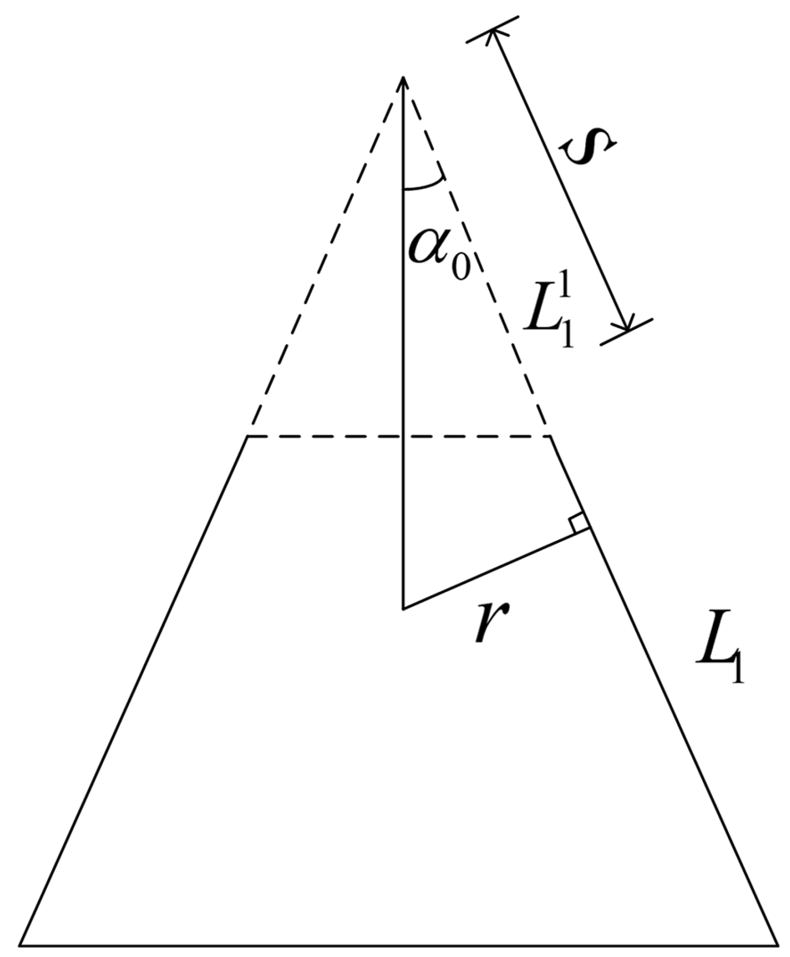
2.1. Theoretical Model

The theoretical model of the umbrella-shaped membrane can be established after the membrane is segmented. The geometric parameters of the polyline can be obtained through the theoretical model according to the segmentation and then substituted into the theoretical calculation process.
In the process of determining the geometrical equation of an umbrella-shaped membrane, the equal stress distribution state is considered, which makes the stresses across the membrane surface equal and maximizes the performance of the material. Catenoid is the only minimal surface with an analytical solution in the rotating surface [15], and this minimal surface is equivalent to the equal stress surface. The equation of catenoid is as follows.
Z = a ln x 2 + y 2 + x 2 + y 2 a 2 ln a + h
The formula above is expressed in the cartesian coordinate system, where x , y are the bottom coordinates; Z is the vertical coordinate, the same as the symmetrical axis direction of the umbrella membrane; a is the top radius of the umbrella membrane; and h is the maximum height of the membrane along the Z axis. The shape of the umbrella-shaped membrane is shown in Figure 1.
Formula (1) in the Cartesian coordinate system is used to determine the shape of the umbrella-shaped membrane. Then, we use the curvilinear coordinate system to facilitate the following calculation process in Figure 2. Let the direction of generatrix and latitude be the two main directions of the orthogonal curvilinear coordinate system. J is the normal direction of the membrane surface, φ is the angle between the normal of the membrane surface and the vertical axis at a point, θ is the angle between the radius of the point and the starting radius in the plane of the weft, and the curve coordinates are taken as φ , θ , J .
The principal curvature radius along direction β is the curvature radius R β of the point on the generatrix. The principal radius of curvature along the θ direction is the distance R θ from a point on the surface to the intersegment point of the normal line and the axis point.
The umbrella-shaped membrane is segmented since the curvature of the membrane varies with the height of the generatrix and the calculation is complicated. Considering that it consists of an infinite number of open conical membranes, the cone angle increases from top to bottom, and the curvature of each segment is constant. By the means of dividing into more segments with a smaller size of each part, the theoretical model will prove more accurate with reasonable geometrical approximation.
The N-segment combination conical membrane is used to replace the original umbrella-shaped membrane. The generatrix length of each segment is L 1 , L 2 , L 3 , L N , and the total length of the generatrix is L. To simplify the calculation, the open conical membrane is extended along the generatrix and calculated according to the closed conical membrane. The extension length of each segment is L 1 1 , L 2 1 , L 3 1 , L N 1 . The following Figure 3 is an analysis of open conical membrane.
For the conical membranes, β = s , the curvilinear coordinates are s , θ , J . The radius of curvature is as follows:
R s = , R θ = r = s tan α 0
α 0 in Formula (2) is the angle between the generatrix and the axis, and the arc length of any segment of the middle surface is ( d S ) 2 = A 2 ( d s ) 2 + B 2 ( d θ ) 2 = ( d s ) 2 + ( r d θ ) 2 . The lame parameters can be obtained as follows:
A = 1 , B = R = s sin α 0

2.2. Basic Governing Equations

Let the three displacement components of any point on the membrane be u ( s , θ ) ,   v ( s , θ ) ,   w ( s , θ , J ) along the curve coordinate s , θ , J . Since the rigidity of the membrane in the normal direction is small and the deformation cannot be neglected, the geometric nonlinearity is considered.
The umbrella-shaped membrane is axisymmetric in structure and load, and its boundary condition is axisymmetric, so the vibration produced is axisymmetric. At this time, all the asymmetric mechanical components are zero and they are functions of coordinate s instead of θ in space.
The continuous deformation conditions for the strain and deflection of the membrane surface can be obtained, that is, the compatibility equation:
ε θ ε s + s ε θ s 1 tan α 0 w s + 1 2 w s 2 = 0
The membrane itself is materially nonlinear elastic, but the constitutive relationship of the membrane itself has not been clearly expressed, and the pretension of the membrane will not exceed the linear elasticity range in the practical engineering design. In this paper, the membrane is treated as linearly elastic and based on the isotropic properties of the ETFE membrane. The fiber direction is the main direction of elasticity, which is now consistent with the direction of coordinate s , θ . Regardless of the material nonlinearity, the Young’s modulus of elasticity in the s , θ direction is E , the shear modulus is G , h is the thickness of the membrane, the Poisson’s ratio is μ .
The expression of internal force is obtained as follows:
N s = K u s + 1 2 w s 2 + μ u s + w s tan α 0 N θ = K u s + w s tan α 0 + μ u s + 1 2 w s 2 N s θ = 0 ,   K = E h 1 μ 2
It is assumed that the membrane surface reaches equilibrium under load, and since the in-plane stiffness is relatively large, u and v are high-order and smaller than w , so the in-plane inertial force is ignored. In addition, due to the axially oriented load, the load component along the generatrix direction, namely q s , is negligible relative to its pretension force; therefore, only the normal direction load is considered. Compared with the membrane areal density, the impact load is small, so considering the influence of membrane gravity in the equation, the equilibrium equation can be obtained from F J = 0 :
( B N s ) s + ( A N θ s ) θ B s N θ + A θ N s θ = 0 ( A N θ ) θ + ( B N s θ ) s A θ N s + B s N θ s = 0 ρ 2 w t 2 + c w t N s 0 + N s 2 w s 2 N θ 0 + N θ 1 s tan α 0 + 2 w θ 2 2 N s θ 2 w s θ = q + ρ g
N s 0 and N θ 0 are the pretension of the membrane direction s , θ , and c is the damping. ρ is the area density of the membrane, g is the acceleration of gravity, N φ and N θ are the tension force of the s , θ direction of the membrane, and q is the impact load per unit area.
For umbrella-shaped membranes, when there is no external load, N φ 0 R φ + N θ 0 R θ = 0 , When the umbrella-shaped membrane segment is simplified as an open conical membrane, we consider that this equation still holds, and the following equation is concluded: N θ 0 1 s tan α 0 = 0 .
By introducing stress function φ s , θ , and by letting the asymmetrical inteSrnal force component be zero, the relationship between the stress increment and stress function of the membrane surface is as follows:
N s = h s φ s N θ = h 2 φ s 2 N s θ = 0
In this way, the first two equations of Equation (6) are satisfied automatically, and then Equation (7) is submitted into the third equation in Equation (6). Ignoring the asymmetric components of the equation, the first equation of unknown variables w and φ can be obtained:
ρ 2 w t 2 + c w t N s 0 + h s φ s 2 w s 2 h 2 φ s 2 1 s tan α 0 = q + ρ g
Formula (7) is substituted into the deformation compatibility Equation (4), and the second equation between w and φ is obtained:
1 E 2 φ s 2 1 s φ s + s E 3 φ s 3 1 tan α 0 w s + 1 2 w s 2 = 0
Equilibrium Equation (8) and deformation compatibility Equation (9) constitute the basic governing equations of dynamic response of conical thin membrane under impact load. Considering the boundary conditions and deformation compatibility conditions of the N-segment conical membranes, the displacement functions are assumed to represent their membrane displacements, respectively.

2.3. Solution of Each Segment of Membrane

In this section, according to the different boundary conditions, the conical membranes that constitute the umbrella membrane are divided into three categories: the first is the top segment, the second is the bottom segment, and the last is the middle segments. The calculation process of each segment is similar, so we only included the calculation process of the first segment here.

The First Segment

The upper end of the first segment of the conical membrane is simply supported. Assuming the displacement and rotation angle of the lower circular boundary, the boundary conditions of the displacement function are expressed as follows:
w ( L 1 1 , θ , t ) = 0 w ( L 1 1 + L 1 , θ , t ) = Δ 1 w s ( L 1 1 + L 1 , θ , t ) = γ 1
Symmetrical vibrations are generated under symmetric loads, so θ is not included in the displacement function, and the displacement function expression that satisfies the overall displacement boundary condition (10) is as follows:
W = W ¯ T ( t ) = ( a 0 + a 1 s 2 + a 2 s 3 ) T ( t )
Substituting Formula (11) into the deformation coordination Equation (9), we obtain the following:
1 E 2 φ s 2 1 s φ s + s E 3 φ s 3 = T ( t ) tan α 0 ( 2 a 1 s + 3 a 2 s 2 ) 1 2 T 2 t ( 2 a 1 s + 3 a 2 s 2 ) 2
Assume that the solution of the stress function in Equation (12) is as follows:
φ ( s , θ , t ) = T ( t ) ϕ 1 ( s , θ ) + T 2 ( t ) ϕ 2 ( s , θ ) ϕ 1 ( s , θ ) = b 0 s 3 + b 1 s 4 ; ϕ 2 ( s , θ ) = b 2 s 4 + b 3 s 5 + b 4 s 6
Substituting Formula (13) into Formula (12), we obtain the following:
b 0 = 2 E a 1 9 tan α 0 , b 1 = 3 E a 2 40 tan α 0 b 2 = E a 1 16 , b 3 = 2 E a 1 a 2 25 , b 4 = E a 2 16
Substituting Formula (14) into Formula (13), we obtain the following:
φ ( s , θ , t ) = 2 E a 1 9 tan α 0 s 3 + 3 E a 2 40 tan α 0 s 4 T ( t ) E a 1 16 s 4 + 2 E a 1 a 2 25 s 5 + E a 2 16 s 6 T 2 ( t )
Substituting Formulas (11) and (13) into Formula (8), we obtain the following by the Galerkin Method:
0 2 π L 1 1 L 1 1 + L 1 ρ a 0 2 + 2 a 0 a 1 s 2 + 2 a 0 a 2 s 3 + a 1 2 s 4 + 2 a 1 a 2 s 5 + a 2 2 s 6 d 2 T t d t 2 + c a 0 2 + 2 a 0 a 1 s 2 + 2 a 0 a 2 s 3 + a 1 2 s 4 + 2 a 1 a 2 s 5 + a 2 2 s 6 d T t d t + T t h tan α 0 6 a 0 b 0 + 12 a 0 b 1 s + 6 a 1 b 0 s 2 + 6 a 2 b 0 + 12 a 1 b 1 s 3 + 12 a 2 b 1 s 4 N ( s 0 2 a 0 a 1 + 6 a 0 a 2 s + 2 a 1 2 s 2 + 8 a 1 a 2 s 3 + 6 a 2 2 s 4 ) + h T 2 t 1 tan α 0 12 a 0 b 2 s + 20 a 0 b 3 s 2 + 30 a 0 b 4 + 12 a 1 b 2 s 3 + 12 a 2 b 2 + 20 a 1 b 3 s 4 + 20 a 2 b 3 + 30 a 1 b 4 s 5 + 30 a 2 b 4 s 6 d s d θ = 0 2 π L 1 1 L 1 1 + L 1 q + ρ g a 0 + a 1 s 2 + a 2 s 3 d s d θ
Let L 1 1 + L 1 n L 1 1 n = K n : after integrating Formula (16), we can obtain the following:
ρ a 0 2 K 1 + 2 3 a 0 a 1 K 3 + 1 2 a 0 a 2 K 4 + 1 5 a 1 2 K 5 + 1 3 a 1 a 2 K 6 + 1 7 a 2 2 K 7 d 2 T t d t 2 + c a 0 2 K 1 + 2 3 a 0 a 1 K 3 + 1 2 a 0 a 2 K 4 + 1 5 a 1 2 K 5 + 1 3 a 1 a 2 K 6 + 1 7 a 2 2 K 7 d T t d t + T t h tan α 0 6 a 0 b 0 K 1 + 6 a 0 b 1 K 2 + 2 a 1 b 0 K 3 + 3 2 a 2 b 0 + 3 a 1 b 1 K 4 + 12 5 a 2 b 1 K 5 N ( s 0 2 a 0 a 1 K 1 + 3 a 0 a 2 K 2 + 2 3 a 1 2 K 3 + 2 a 1 a 2 K 4 + 6 5 a 2 2 K 5 ) + h T 2 t 1 tan α 0 6 a 0 b 2 K 2 + 20 3 a 0 b 3 K 3 + 15 2 a 0 b 4 + 3 a 1 b 2 K 4 + 12 5 a 2 b 2 + 4 a 1 b 3 K 5 + 10 3 a 2 b 3 + 5 a 1 b 4 K 6 + 30 7 a 2 b 4 K 7 = q + ρ g a 0 K 1 + 1 3 a 1 K 3 + 1 4 a 2 K 4
Simplifying the above parameters, we obtain the following:
α = 1 ρ a 0 2 K 1 + 2 3 a 0 a 1 K 3 + 1 2 a 0 a 2 K 4 + 1 5 a 1 2 K 5 + 1 3 a 1 a 2 K 6 + 1 7 a 2 2 K 7 ω 0 2 = α h tan α 0 6 a 0 b 0 K 1 + 6 a 0 b 1 K 2 + 2 a 1 b 0 K 3 + 3 2 a 2 b 0 + 3 a 1 b 1 K 4 + 12 5 a 2 b 1 K 5 N ( s 0 2 a 0 a 1 K 1 + 3 a 0 a 2 K 2 + 2 3 a 1 2 K 3 + 2 a 1 a 2 K 4 + 6 5 a 2 2 K 5 ) α 1 = α L 1 2 ω 0 2 h 1 tan α 0 6 a 0 b 2 K 2 + 20 3 a 0 b 3 K 3 + 15 2 a 0 b 4 + 3 a 1 b 2 K 4 + 12 5 a 2 b 2 + 4 a 1 b 3 K 5 + 10 3 a 2 b 3 + 5 a 1 b 4 K 6 + 30 7 a 2 b 4 K 7 α 2 = c 2 ρ X t = α q + ρ g a 0 K 1 + 1 3 a 1 K 3 + 1 4 a 2 K 4
The small parameter perturbation method [16] is used to solve the governing equation, and the perturbation parameter ε = h 2 L 1 2 1 is set to simplify Formula (17):
d 2 T t d t 2 + 2 α 2 d T t d t + ω 0 2 T t + ε α 1 T 2 t = X t
The expansion of T ( t ) into the power series of small parameter ε yields the following:
T ( t ) = T 0 ( t ) + ε T 1 ( t ) + ε 2 T 2 ( t ) + 0 ( ε 3 )
Formula (18) is substituted into Formula (19), and two terms are taken for T ( t ) . The approximate calculation results are as follows:
d 2 T 0 t d t 2 + ε d 2 T 1 t d t 2 + ε 2 d 2 T 2 t d t 2 + 2 α 3 d T 0 t d t + ε d T 1 t d t + ε 2 d T 2 t d t + ω 0 2 T 0 t + ε T 1 t + ε 2 T 2 t + ε α 1 T 0 t + ε T 1 t + ε 2 T 2 t 2 + ε α 2 [ T 0 t + ε T 1 t + ε 2 T 2 t ] 3 } = X t
By expanding and comparing the coefficients of the same power of ε at both ends of the equation, the linear differential equation is obtained as follows:
d 2 T 0 t d t 2 + 2 α 3 d T 0 t d t + ω 0 2 T 0 t = X t d 2 T 1 t d t 2 + 2 α 3 d T 1 t d t + ω 0 2 T 1 t = ω 0 2 α 1 T 0 2 t ω 0 2 α 2 T 0 3 t d 2 T 2 t d t 2 + 2 α 3 d T 2 t d t + ω 0 2 T 2 t = 2 ω 0 2 α 1 T 0 t T 1 t 3 ω 0 2 α 2 T 0 2 t T 1 t
According to the theory of the linear stationary stochastic process, the equations are solved for (21):
T 0 t = + h n X ( t n ) d n T 1 t = + h n g 1 ( t n ) d n T 2 t = + h n g 2 ( t n ) d n
h n in the formula is the impulse response function of the linear differential operator d 2 d t 2 + 2 α 3 d d t + ω 0 2 . The relevant parameters are as follows:
h n = e α 3 n ω 0 2 α 3 2 sin ω 0 2 α 3 2 n g 1 t = ω 0 2 α 1 T 0 2 t ω 0 2 α 2 T 0 3 t g 2 t = 2 ω 0 2 α 1 T 0 t T 1 t 3 ω 0 2 α 2 T 0 2 t T 1 t
In the theoretical calculation, the three kinds of heavy rainfall are substituted into the theoretical calculation. Assuming that the rainstorm load is the uniform impact load [17], let q = F δ ( t t k ) , where F is the value of load, δ ( t t k ) is Dirac Function, and t k is the moment of load action.
The approximate calculation of T t by Formula (19) takes the first order of ε , that is, T ( t ) = T 0 t + ε T 1 t , then:
T 0 t = 1 ρ 0 t e α 3 n ω 0 2 α 3 2 sin ω 0 2 α 3 2 n ρ g + k = 1 N ( T ) Y k δ ( t n τ k ) d n = 1 ρ ω 0 2 α 3 2 k = 1 N ( T ) Y k e α 3 ( t τ k ) sin ω 0 2 α 3 2 t t k g ρ ω 0 2 e α 3 t ω 0 2 α 3 2 α 3 sin ω 0 2 α 3 2 t + e α 3 t cos ω 0 2 α 3 2 t 1
T 1 t = 0 t e α 3 n ω 0 2 α 3 2 sin ω 0 2 α 3 2 n ω 0 2 α 1 T 0 2 t n ω 0 2 α 2 T 0 3 t n d n = ω 0 2 ω 0 2 α 3 2 0 t e α 3 n sin ω 0 2 α 3 2 n α 1 1 ρ ω 0 2 α 3 2 F e α 3 ( t n t k ) sin ω 0 2 α 3 2 t n t k g ω 0 2 e α 3 ( t n ) ω 0 2 α 3 2 α 3 sin ω 0 2 α 3 2 ( t n ) + e α 3 ( t n ) cos ω 0 2 α 3 2 ( t n ) 1 2 + α 2 1 ρ ω 0 2 α 3 2 F e α 3 ( t n t k ) sin ω 0 2 α 3 2 t n t k g ω 0 2 e α 3 ( t n ) ω 0 2 α 3 2 α 3 sin ω 0 2 α 3 2 ( t n ) + e α 3 ( t n ) cos ω 0 2 α 3 2 ( t n ) 1 3 d n
Substituting (24) and (25) into Formula (19), and then substituting Formula (19) into Formula (21), we obtain the following:
W s , θ , t = a 0 + a 1 s 2 + a 2 s 3 T t = a 0 + a 1 s 2 + a 2 s 3 [ T 0 t + ε T 1 t ] = a 0 + a 1 s 2 + a 2 s 3 { T 0 t + ε ω 0 2 ω 0 2 α 3 2 0 t e α 3 n sin ω 0 2 α 3 2 n α 1 T 0 2 t n + α 2 T 0 3 t n d n

3. Membrane Segmentation and Case Analysis

3.1. Membrane Segmentation

When the umbrella-shaped membrane is segmented, the geometry of the membrane formed by the combination of the segments should be similar to the original, and the difference mainly reflected by their generatrix. We named the sum of generatrix length of the segmented membrane as L S , and the original membrane’s generatrix length as L O . With an increase in the number of segments, L S increases, but it is always smaller than L O . When the number of segments is defined, we think that when L S is the largest, the corresponding segment points are exactly what we need.
In the following case analysis, the umbrella-shaped membrane is divided into one, three, five, and seven segments. Taking the umbrella membrane with a height–span ratio of 0.15 as an example, the top radius is 0.2 m, the bottom radius is 2 m, the height is 0.6 m, and L O is 1.99 m. With different segmenting numbers, L S is as follows: 1.8969 m, 1.9794 m, 1.9862 m, and 1.988 m. We assumed that with the increase in the segmenting numbers, L S will gradually increase and approach L O , which supports our hypothesis.

3.2. Case Analysis

The ETFE membrane materials commonly used in engineering were adopted in the theoretical calculation in this section, which are isotropic. Considering the form of single-layer tension, the material is kept in a linear elastic range [18] by applying a pretension less than 15 MPa in two directions. Three kinds of heavy rainfall of different sizes are considered, which are 50 mm/h, 300 mm/h, and 550 mm/h respectively. The range of pretension is 1 kN to 3 kN, increasing by 0.25 kN each time.
Considering the diversity of umbrella-shaped membranes in practical engineering, different height–span ratios are used in the calculation, which are 0.1, 0.15, 0.2, and the radius of the bottom is 2 m. According to the catenary surface in Equation (1), the height and top radii of the umbrella-shaped membrane with various height–span ratios are calculated, and each umbrella-shaped membrane is segmented separately. Finally, all parameters required for theoretical calculation are obtained.
The basic parameters of the ETFE membrane material used in the calculation are as follows in Table 1:
For umbrella-shaped membranes with a height–span ratio of 0.5, its bottom radius is 2 m, the height is 0.4 m, and the top radius is 0.112 m, as obtained through calculation. The position of the midpoint of the umbrella-shaped membrane span is determined by its generatrix and the horizontal distance between point A, and the center of the circle is 1.1 m. While it is divided into seven segments, the displacement function is obtained as follows:
w = 0.0327 + 3.3314 s 2 2.9787 s 3 + 0.6599 s 4
Similarly, for the umbrella membranes with a height–span ratio of 0.15 and 0.2, their bottom radius is 2 m, their height is 0.6 m and 0.8 m, and their top radius is 0.2 m and 0.316 m. Their geometry will not be drawn here. In addition, we have determined mid span point A’s position and displacement function, respectively.

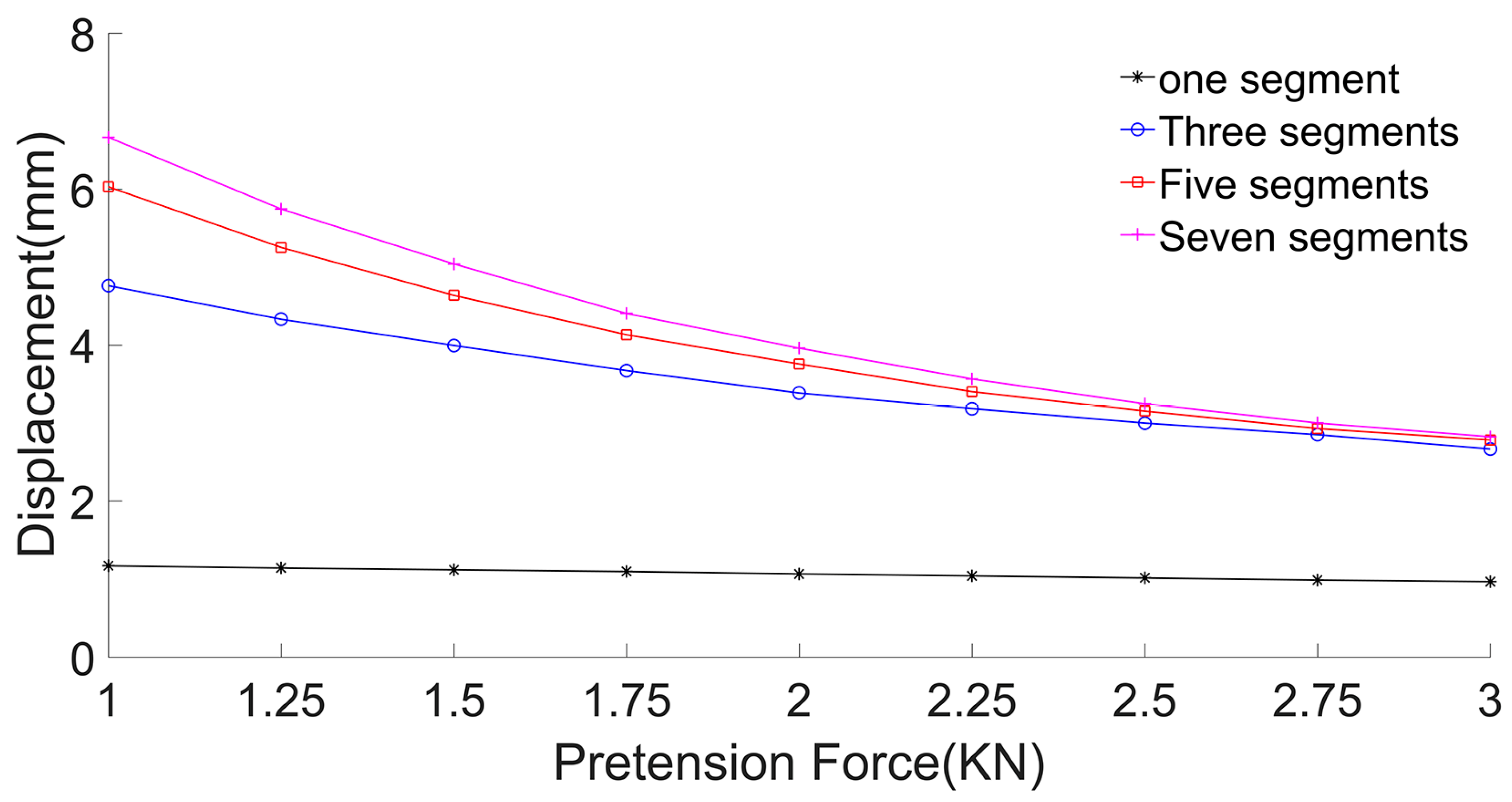
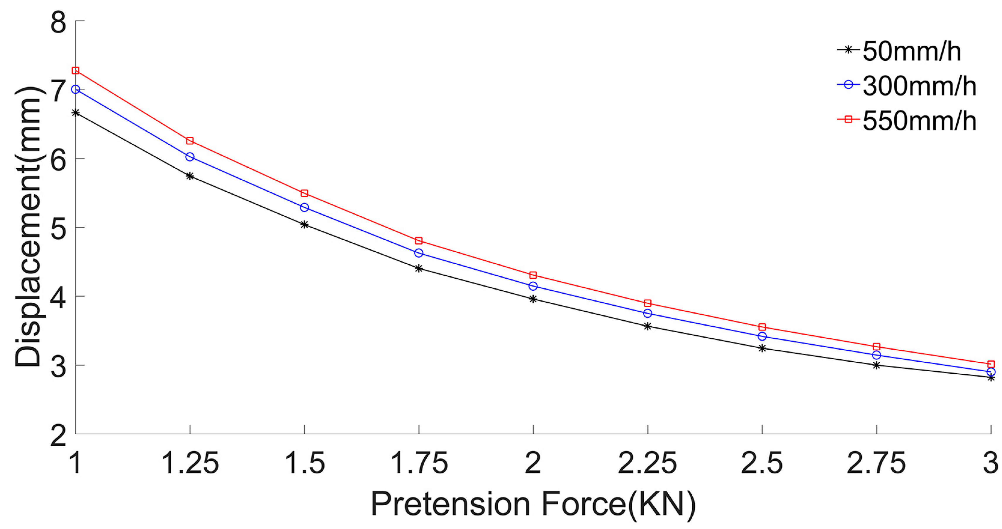
3.2.1. Displacement Calculation

The displacement of the umbrella membrane with a height–span ratio of 0.1 is calculated under the rainstorm load of 50 mm/h. The maximum displacement of the membrane surface at point A under different segmenting forms and pretensions is shown in the following Figure 4:
Under the same load, for the same umbrella membrane, with an increase in the number of segments, the calculation results of membrane displacement increase gradually.
Next, from the three- to seven-segment membranes, the change rate of the displacement calculated results of each segmenting form with respect to the former segmenting form is calculated, as shown in Table 2:
From the observation of the data in the table, it can be seen that with the increase in pretension or the number of segments, the influence of segmenting numbers on the results decreases. With the increase in segmenting numbers, the solution tends to be more accurate.
Next, the influence of different heavy rainfalls and pretensions on the membrane displacement at point A is compared and analyzed. Taking the seven segments of the membrane as an example, the calculation results are as follows.
Figure 5 demonstrates that for identical umbrella membranes, under the same pretension, with the increase in heavy rainfall, the displacement of the membrane increases; under the same load, with the increase in pretension, the displacement of the umbrella membrane decreases.
In order to analyze the influence of the height–span ratio on the membrane displacement calculation results under the heavy rainfall, we selected the heavy rainfall of 50 mm/h and divided the umbrella-shaped membrane with the height–span ratio of 0.1, 0.15, and 0.2 into seven segments for calculation. The maximum displacement of the membrane surface at point A with different pretensions is calculated and the comparison results are shown in Figure 6 below:
It can be seen from the calculation results that, for the umbrella-shaped membrane with different height–span ratios, the membrane displacement decreases with the increase in height–span ratio under the same segmenting form and the same load.

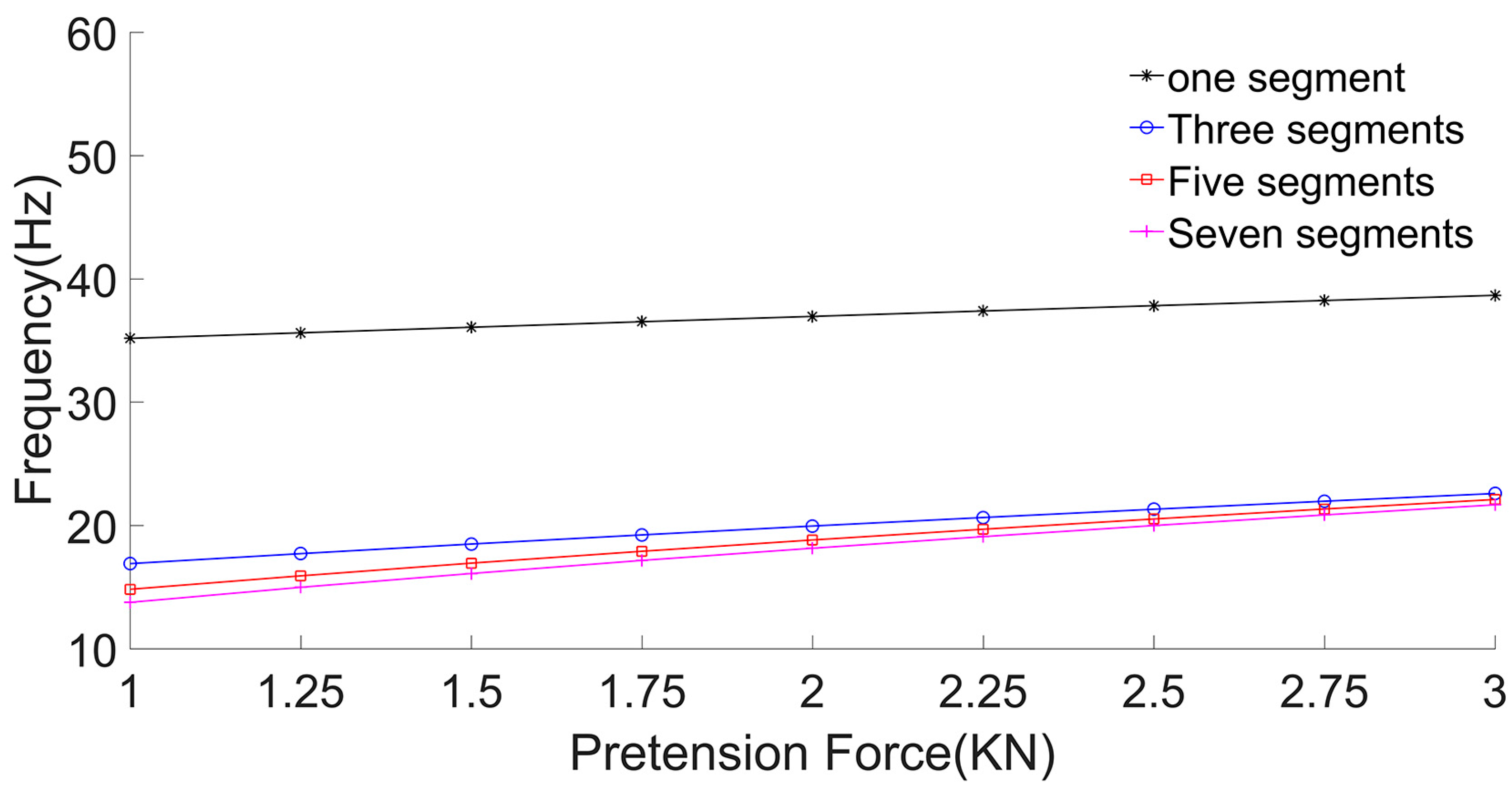
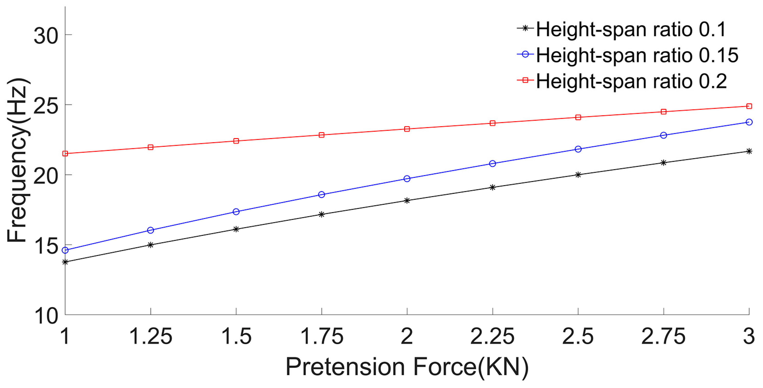
3.2.2. Frequency Calculation

According to Formulas (24) and (25), the vibration frequency of the membrane surface at point A is calculated. Because the displacement function is too complex, we ignore the influence of T 1 t in the calculation result, and the simplified displacement function is as follows:
W s , θ , t = a 0 + a 1 s 2 + a 2 s 3 T t = a 0 + a 1 s 2 + a 2 s 3 T 0 t = a 0 + a 1 s 2 + a 2 s 3 1 ρ ω 0 2 α 3 2 k = 1 N ( T ) Y k e α 3 ( t τ k ) sin ω 0 2 α 3 2 t t k g ρ ω 0 2 e α 3 t ω 0 2 α 3 2 α 3 sin ω 0 2 α 3 2 t + e α 3 t cos ω 0 2 α 3 2 t 1
The frequency expression of point A can be obtained by the following formula:
f = ω 0 2 α 3 2 / 2 π
From the frequency expression, we can see that the vibration frequency of point A is determined by ω 0 , α 3 , while ω 0 and α 3 are related to the thickness, density, damping, cone angle, and displacement function of the umbrella membrane, and the change of rainfall will not affect the frequency.
The vibration frequency of the umbrella membrane with a height–span ratio of 0.1 is calculated under the heavy rainfall of 50 mm/h. The vibration frequency of the membrane surface at point A under different segmenting forms and pretensions is shown in the following Figure 7:
It can be seen from the above figure that for the same umbrella-shaped membrane, under the same load, with the increase in the number of segments, the calculation result of the membrane surface vibration frequency decreases; with the increase in pretension, the membrane surface vibration frequency increases.
Next, from the three- to seven-segment membranes, the change rate of the frequency calculated results of each segmenting form with respect to the former segmenting form is calculated, as shown in the Table 3 below:
It can be seen that with the increase in pretension or segmenting numbers, the influence of segmenting numbers on the results decreases. With an increase in segmenting numbers, the solution tends to be more accurate.
In order to analyze the influence of the height–span ratio on the membrane frequency calculation results under the heavy rainfall, we select the heavy rainfall of 50 mm/h and divide the umbrella-shaped membrane with the height–span ratio of 0.1, 0.15, and 0.2 into seven segments for calculation. The frequency of the membrane surface at point A under different pretensions is calculated and the comparison results are as follows in Figure 8:
It can be seen from the calculation results that under the same heavy rainfall and pretension, with an increase in the height–span ratio, the vibration frequency of the umbrella-shaped membrane increases.

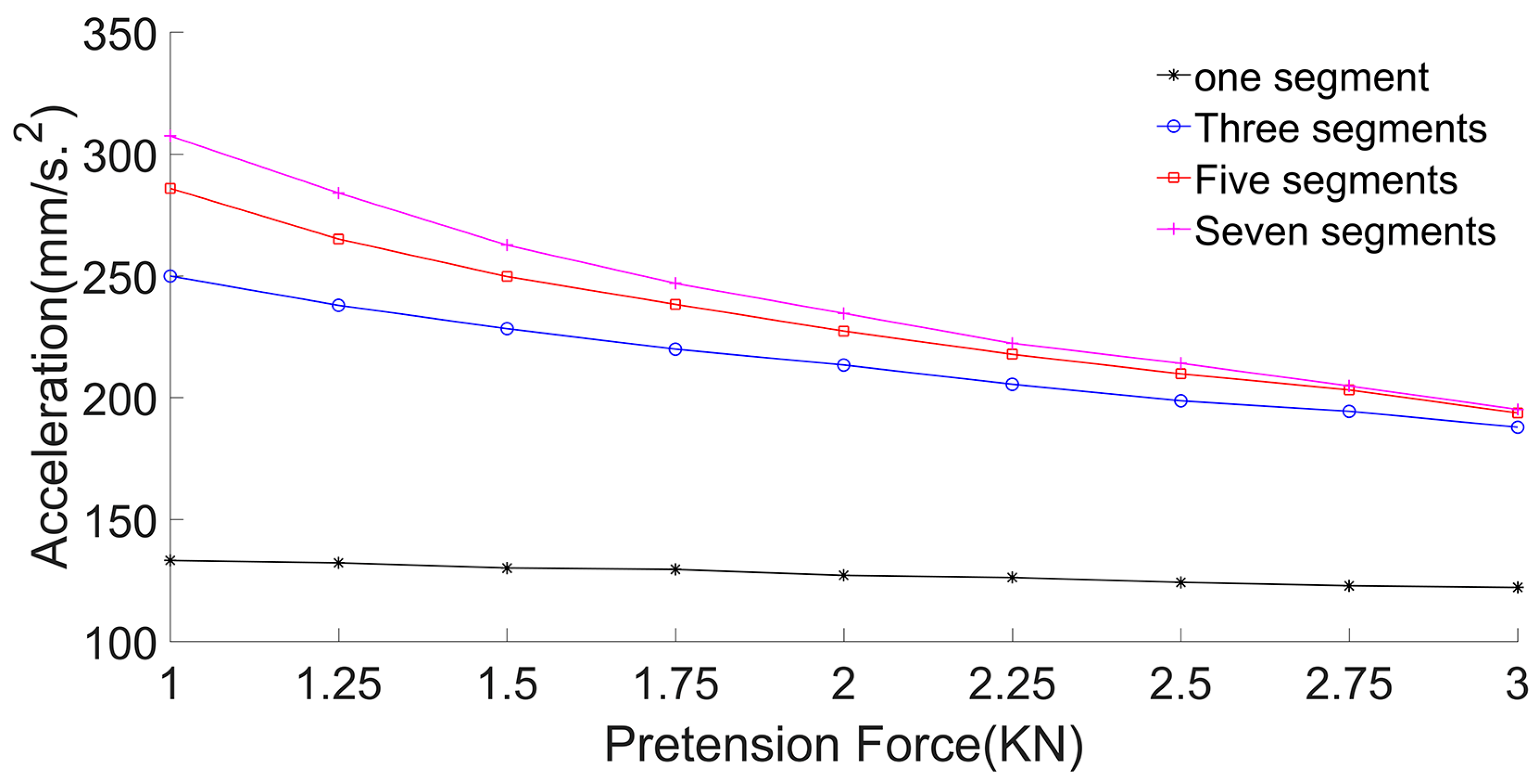
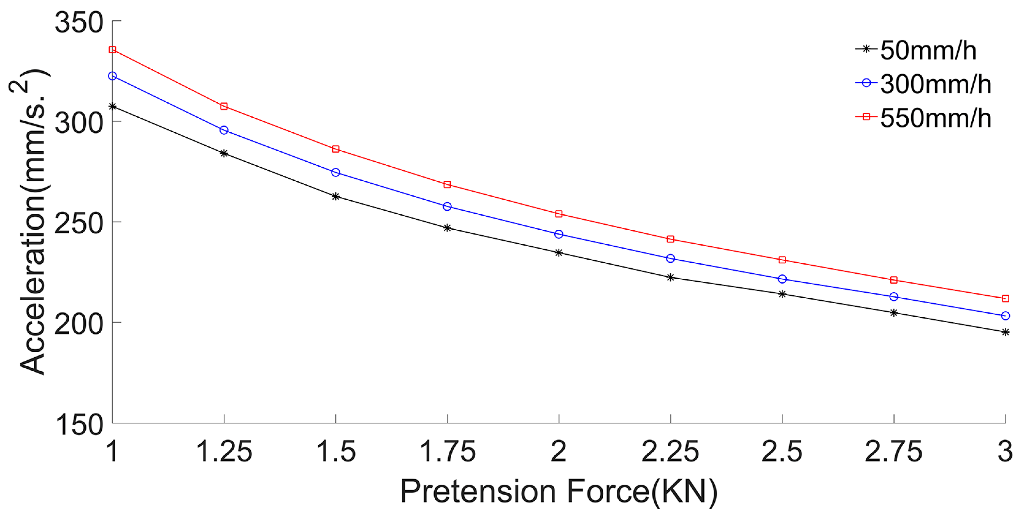
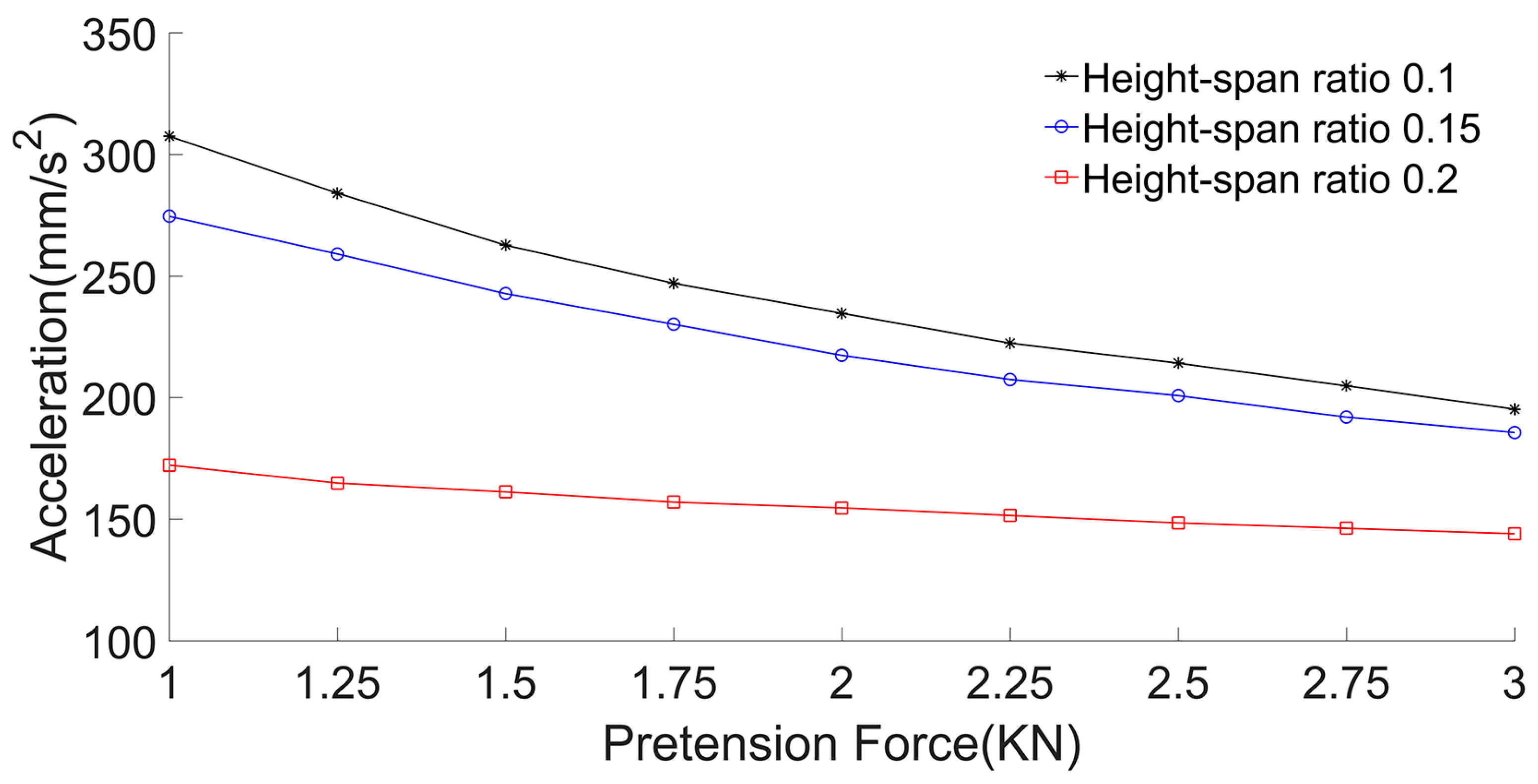
3.2.3. Acceleration Calculation

In order to calculate the acceleration of the membrane surface at point A of the umbrella-shaped membrane, Formulas (24) and (25) are first derived as follows:
T 0 t t = 1 ρ ω 0 2 α 3 2 ω 0 2 α 3 2 k = 1 N ( T ) Y k e α 3 ( t τ k ) cos ω 0 2 α 3 2 t t k α 3 k = 1 N ( T ) Y k e α 3 ( t τ k ) sin ω 0 2 α 3 2 t t k + g ρ ω 0 2 α 3 2 e α 3 t ω 0 2 α 3 2 sin ω 0 2 α 3 2 t + e α 3 t ω 0 2 α 3 2 sin ω 0 2 α 3 2 t
T 1 t t = 0 t e α 3 n ω 0 2 α 3 2 sin ω 0 2 α 3 2 n ω 0 2 α 1 T 0 2 t n ω 0 2 α 2 T 0 3 t n d n = e α 3 t ω 0 2 ω 0 2 α 3 2 sin ω 0 2 α 3 2 t α 1 T 0 2 t + α 2 T 0 3 t
Then the above two expressions are substituted into the displacement function expression (26), and the acceleration is obtained:
a s , t = a 0 + a 1 s 2 + a 2 s 3 a t = a 0 + a 1 s 2 + a 2 s 3 T 0 t t + ε T 1 t t = a 0 + a 1 s 2 + a 2 s 3 T 0 t + ε e α 3 t ω 0 2 ω 0 2 α 3 2 sin ω 0 2 α 3 2 t α 1 T 0 2 t + α 2 T 0 3 t
The acceleration of the umbrella-shaped membrane with a height–span ratio of 0.1 under the heavy rainfall of 50 mm/h is calculated. The acceleration of the membrane surface at point A under different segmenting forms and pretensions is as follows in Figure 9:
It can be seen from the above figure that for the same umbrella-shaped membrane, under the same loads, with an increase in pretension, the acceleration decreases.
Next, from the three- to seven-segment membranes, the change rate of the acceleration calculated results of each segmenting form with respect to the former segmenting form is calculated, as shown in the Table 4 below:
It can be seen that with an increase in segmenting numbers, the influence of segmenting numbers on the calculation results decreases, and the results tend to be more accurate.
Next, the influence of different loads and pretensions on the membrane acceleration at point A is compared and analyzed. Taking the seven-segment membrane as an example, the calculation results are as follows in Figure 10:
It can be seen that for the same umbrella-shaped membrane, under the same pretension, with the increase in load, the acceleration of the membrane surface increases; under the same load, with an increase in pretension, the displacement acceleration of the membrane surface decreases.
In order to analyze the influence of the height–span ratio on the membrane acceleration calculation results under the heavy rainfall, we select the heavy rainfall of 50 mm/h and divide the umbrella-shaped membrane with the height–span ratio of 0.1, 0.15, and 0.2 into seven segments for calculation. The acceleration of the membrane surface at point A under different pretensions is calculated, and the comparison results are as follows in Figure 11:
It can be seen from the calculation results that for the umbrella-shaped membranes with different height–span ratios, the acceleration of the membrane surface decreases gradually with the increase in height–span ratio under the same load.

4. Conclusions

In this paper, we propose an approximate solution for umbrella-shaped membrane’s dynamic response under impact loads by dividing it into a simple conical model with constant curvature. The above research process preliminarily verifies the reliability and applicability of the theoretical method. At the same time, based on the theoretical calculation, the general law of vibration deformation of the umbrella-shaped membrane under heavy rainfall is obtained, which provides data and method reference for the design and construction of the membrane structure. Here we put forward some ideas for further improving the calculation accuracy and simplifying the calculation process, which are as follows:
(1)
Based on the conclusions in Section 3.2, which are consistent with theoretical research and basic mechanical knowledge, we believe that the research method in this paper is feasible to solve the vibration response of the umbrella membrane with complex curvature under the action of heavy rainfall.
(2)
With an increase in the number of segments, the influence of the number of segments on the results of membrane displacement, frequency, and acceleration decreases, and the solution tends to be more accurate.
(3)
The simplification of the displacement function is helpful to reduce the difficulty of calculation, and it can be further studied. For the geometrically nonlinear and orthotropic characteristics of the membrane materials, as well as the effects of different types of loads, further research is needed.

5. Discussions

The theoretical model in this study is based on commonly existing umbrella-shaped membrane structures. However, research on the vibration response of such structures remains limited, and their curved surfaces significantly complicate the calculations. To address this, we employed a segmented calculation approach and attempted to improve accuracy by increasing the number of segments. Nevertheless, substantial work remains to be done. Our research group’s future directions include the following:
(1)
Enhancing the theoretical framework by incorporating commonly used anisotropic materials, actual dimensions, and other typical loading conditions to refine and expand the theoretical system.
(2)
Validating theoretical results through experiments and finite element analysis, comparing the data with current theoretical findings to verify their accuracy.
(3)
Providing practical engineering support by conducting a series of studies on umbrella-shaped membrane structures to better understand their structural behavior and assist in real-world construction and maintenance.

Author Contributions

The overall idea and implementation method of the paper, Z.L. and Z.Z. Calculation and formula derivation, R.Y. literature search and paper verification, P.Z. All authors have read and agreed to the published version of the manuscript.

Funding

This research received no specific grant from any funding agency in the public, commercial, or not-for-profit sectors.

Data Availability Statement

Data are contained within the article.

Conflicts of Interest

Author Rui Yang was employed by the company China Southwest Architectural Design and Research Institute Co., Ltd. The remaining authors declare that the research was conducted in the absence of any commercial or financial relationships that could be construed as a potential conflict of interest.

References

  1. Hincz, K.; Gamboa-Marrufo, M. Deformed Shape Wind Analysis of Tensile Membrane Structures. J. Struct. Eng. 2016, 142, 1–5. [Google Scholar] [CrossRef]
  2. Dutta, S.; Ghosh, S.; Inamdar, M.M. Optimisation of tensile membrane structures under uncertain wind loads using PCE and kriging based metamodels. Struct. Multidiscip. Optim. 2018, 57, 1149–1161. [Google Scholar] [CrossRef]
  3. Beatini, V.; Carfagni, G.R. Large transformations with moderate strains of tensile membrane structures. Math. Mech. Solids 2017, 22, 1117–1137. [Google Scholar] [CrossRef]
  4. Stranghöner, N. Tensile membrane structures. Steel Constr. 2015, 8, 221. [Google Scholar] [CrossRef]
  5. Li, D.; Zheng, Z.L.; He, C.; Liu, C.Y. Dynamic response of pre-stressed orthotropic circular membrane under impact load. J. Vib. Control. 2018, 24, 4010–4022. [Google Scholar] [CrossRef]
  6. Zheng, Z.L.; Liu, C.Y.; Li, D.; Zhang, T. Dynamic Response of Orthotropic Membrane Structure under Impact Load based on Multiple Scale Perturbation Method. Lat. Am. J. Solids Struct. 2017, 14, 1490–1505. [Google Scholar] [CrossRef]
  7. Nagaya, K. Transient response of a circular membrane to an eccentric annular impact load. J. Sound Vib. 1977, 55, 215–223. [Google Scholar] [CrossRef]
  8. Li, D.; Zheng, Z.L.; Liu, C.-Y.; Zhang, G.-X.; Lian, Y.-S.; Tian, Y.; Xiao, Y.; Xie, X.-M. Dynamic response of rectangular prestressed membrane subjected to uniform impact load. Arch. Civ. Mech. Eng. 2017, 17, 586–598. [Google Scholar] [CrossRef]
  9. Liu, C.J.; Deng, X.W.; Liu, J.; Zheng, Z.L. Impact-induced nonlinear damped vibration of fabric membrane structure: Theory, analysis, experiment and parametric study. Compos. Part Eng. 2019, 159, 389–404. [Google Scholar] [CrossRef]
  10. Kumazawa, H.; Susuki, I.; Hasegawa, O.; Kasano, H. Influence of Biaxial Loads on Impact Fracture of High-Strength Membrane Materials. Adv. Compos. Mater. 2009, 18, 395–413. [Google Scholar] [CrossRef]
  11. Rank, E.; Halfmann, A. Wind loads on lightweight structures: Numerical simulation and wind tunnel tests. GAMM-Mitteilungen 2005, 28, 73–89. [Google Scholar] [CrossRef]
  12. Sun, X.Y.; He, R. Numerical simulation of snowdrift on a membrane roof and the mechanical performance under snow loads. Cold Reg. Sci. Technol. 2018, 150, 15–24. [Google Scholar] [CrossRef]
  13. Michalski, A.; Gawenat, B.; Gelenne, P.; Haug, E. Computational wind engineering of large umbrella structures. J. Wind. Eng. Ind. Aerodyn. 2015, 144, 96–107. [Google Scholar] [CrossRef]
  14. Michalski, A.; Haug, E.; Bradatsch, J.; Bletzinger, K.U. Virtual Design Methodology for Lightweight Structures—Aerodynamic Response of Membrane Structures. Int. J. Space Struct. 2019, 24, 211–221. [Google Scholar] [CrossRef]
  15. Gründig, L. Minimal surfaces for finding forms of structural membranes. Comput. Struct. 1988, 30, 679–683. [Google Scholar] [CrossRef]
  16. Nayfeh, A. Perturbation Methods; Wiley Interscience: Hoboken, NJ, USA, 1973. [Google Scholar]
  17. Zheng, Z.L.; Zhang, G.X.; Li, D.; Liu, C.J. Dynamic response of rectangular membrane excited by heavy rainfall. J. Vib. Control 2019, 25, 777–792. [Google Scholar] [CrossRef]
  18. Galliot, C.; Luchsinger, R.H. Uniaxial and biaxial mechanical properties of ETFE foils. Polym. Test. 2011, 30, 356–365. [Google Scholar] [CrossRef]
Figure 1. Shape of umbrella-type membrane.
Buildings 15 02529 g001
Figure 2. Vertical segment and perspective of umbrella-type membrane.
Buildings 15 02529 g002
Figure 3. Conical membrane formed by extension of generatrix.
Buildings 15 02529 g003
Figure 4. The maximum displacement comparison of point A under the rainstorm load of 50 mm/h.
Buildings 15 02529 g004
Figure 5. Displacement comparison of point A under different loads and pretension forces.
Buildings 15 02529 g005
Figure 6. Displacement comparison of point A with different height–span ratios.
Buildings 15 02529 g006
Figure 7. The effect of pretension and segment number on the vibration frequency of the membrane.
Buildings 15 02529 g007
Figure 8. Frequency comparison of point A with different height–span ratios.
Buildings 15 02529 g008
Figure 9. The effect of segment number on the acceleration of the membrane.
Buildings 15 02529 g009
Figure 10. The effect of loads and pretension on the acceleration of membrane.
Buildings 15 02529 g010
Figure 11. Acceleration comparison of point A with different height–span ratio.
Buildings 15 02529 g011
Table 1. Material properties of membrane materials.
Typeh (mm)Poisson RatioE (MPa)ρ (kg/m2)
ETFE0.250.3810000.4375
Table 2. Change of displacement caused by increase in membrane segments.
SegmentsPretension (kN)
11.251.51.7522.252.52.753
3307%280%257%235%220%206%196%189%176%
526.6%21.3%16.1%12.5%10%7.83%5.11%3.48%2.81%
710.6%9.37%8.26%6.61%5.43%3.88%2.98%2.07%1.86%
Table 3. Change of frequency caused by increase in membrane segments.
SegmentsPretension (kN)
11.251.51.7522.252.52.753
352%50.3%48.7%47.3%46%44.8%43.7%42.6%41.6%
512.3%10.2%8.38%6.92%5.66%4.60%3.71%2.87%2.17%
77.15%5.85%4.96%4.13%3.56%3.05%2.58%2.25%1.95%
Table 4. Change of acceleration caused by increase in membrane segments.
SegmentsPretension (kN)
11.251.51.7522.252.52.753
387.6%80%75.3%69.8%66.8%62.8%60%57.3%53.9%
514.4%11.4%9.52%8.05%7.08%5.99%5.08%4.19%3.09%
77.52%6.37%5.17%3.91%3.08%2.48%2.06%1.59%0.77%
Disclaimer/Publisher’s Note: The statements, opinions and data contained in all publications are solely those of the individual author(s) and contributor(s) and not of MDPI and/or the editor(s). MDPI and/or the editor(s) disclaim responsibility for any injury to people or property resulting from any ideas, methods, instructions or products referred to in the content.

