
Seismic Performance and Moment–Rotation Relationship Modeling of Novel Prefabricated Frame Joints

Abstract
1. Introduction
2. Experimental Programs
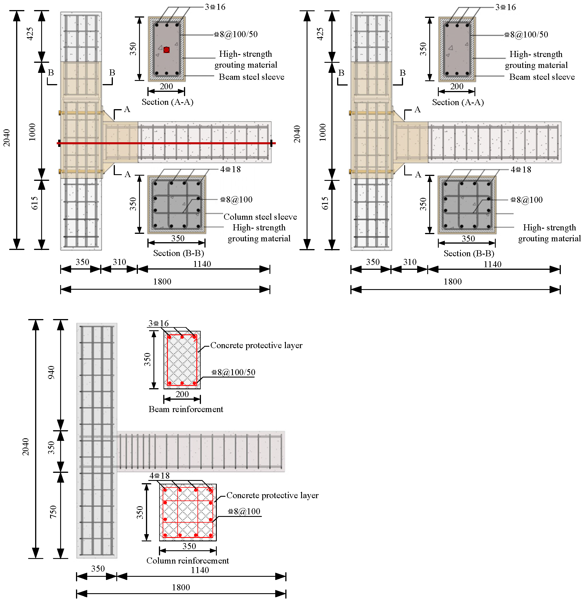
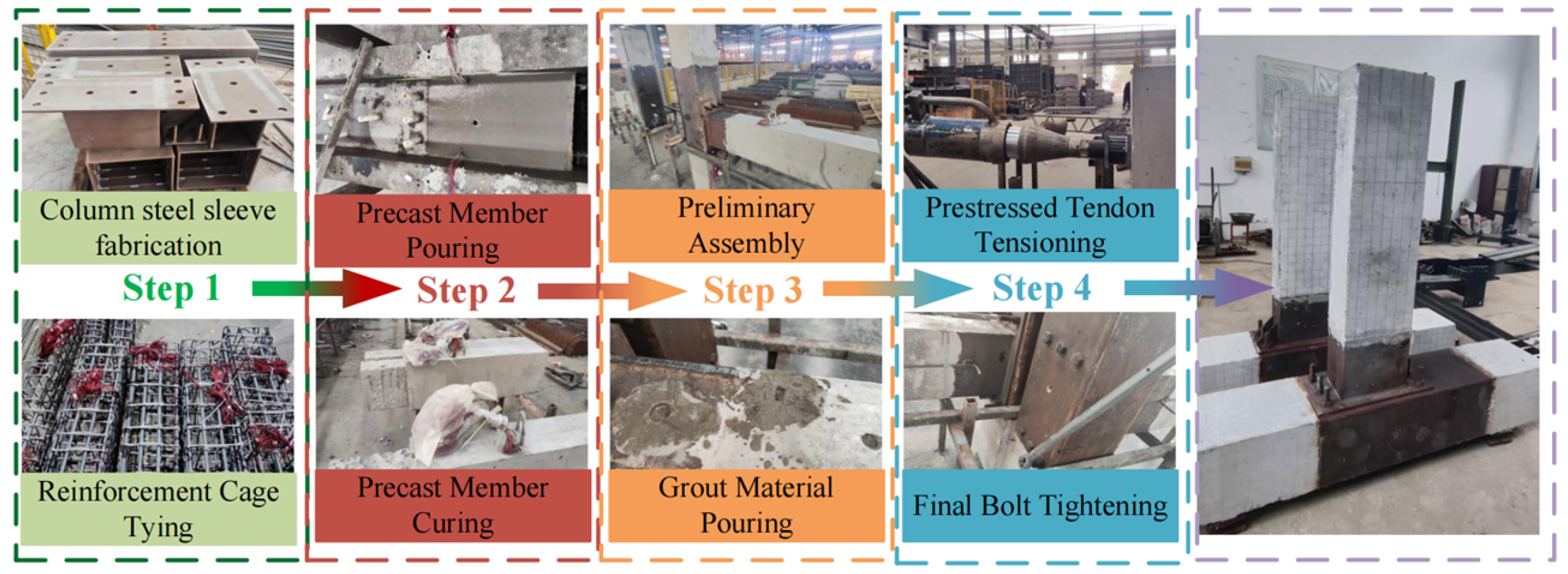
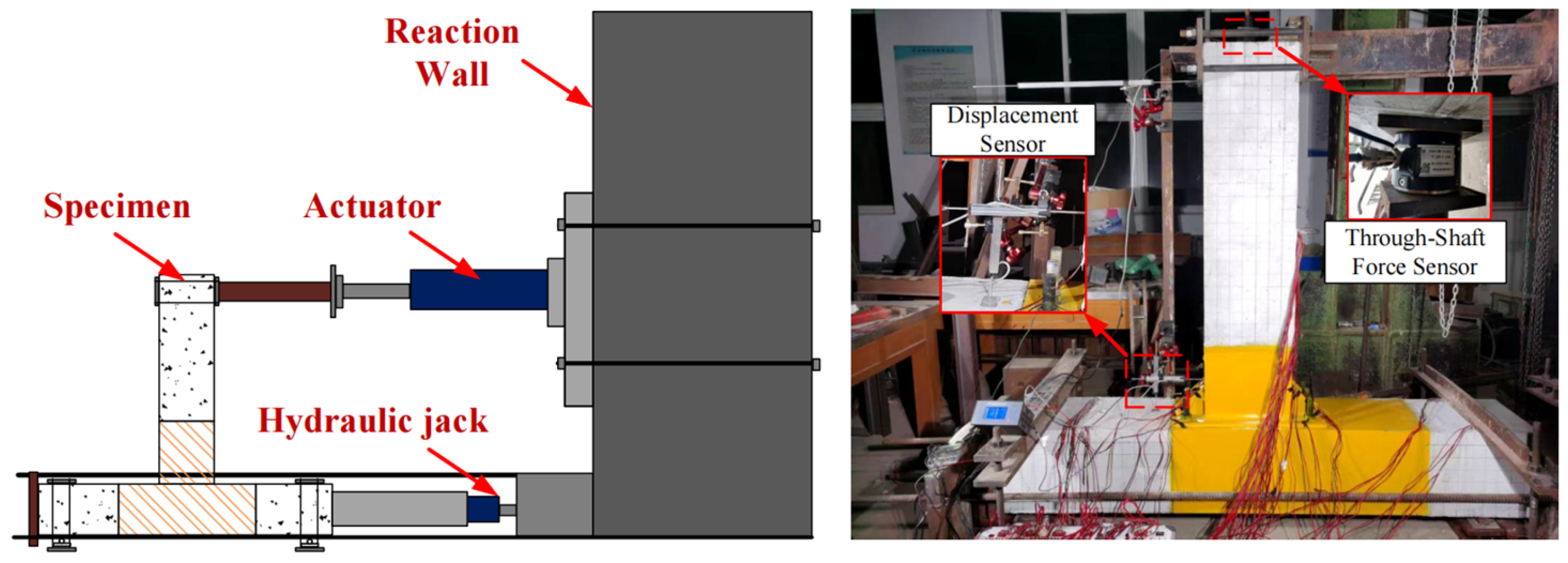
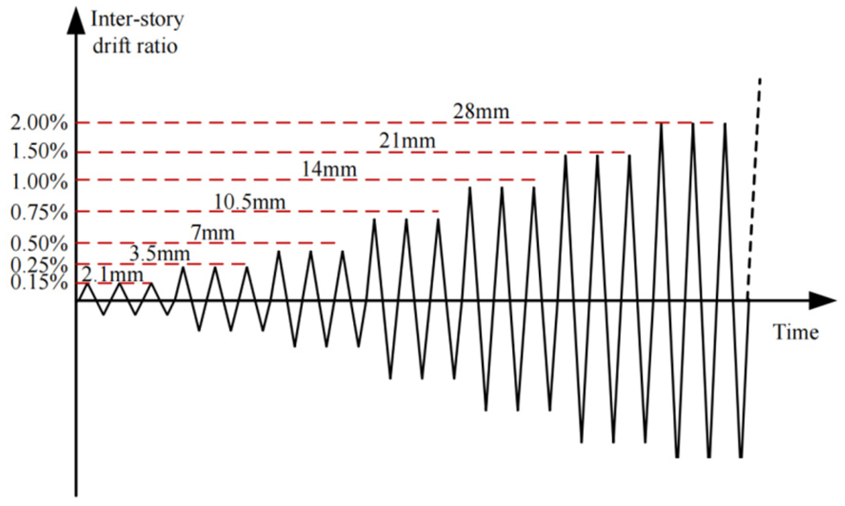
Specimen Design and Testing Program
3. Experimental Results of Tests
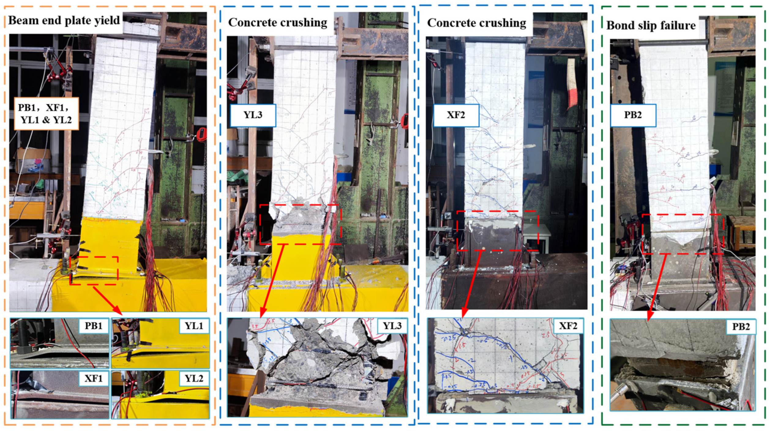
3.1. Damage Phenomena and Analysis
3.2. Parametric Analysis of the Specimens’ Seismic Performance
- (1)
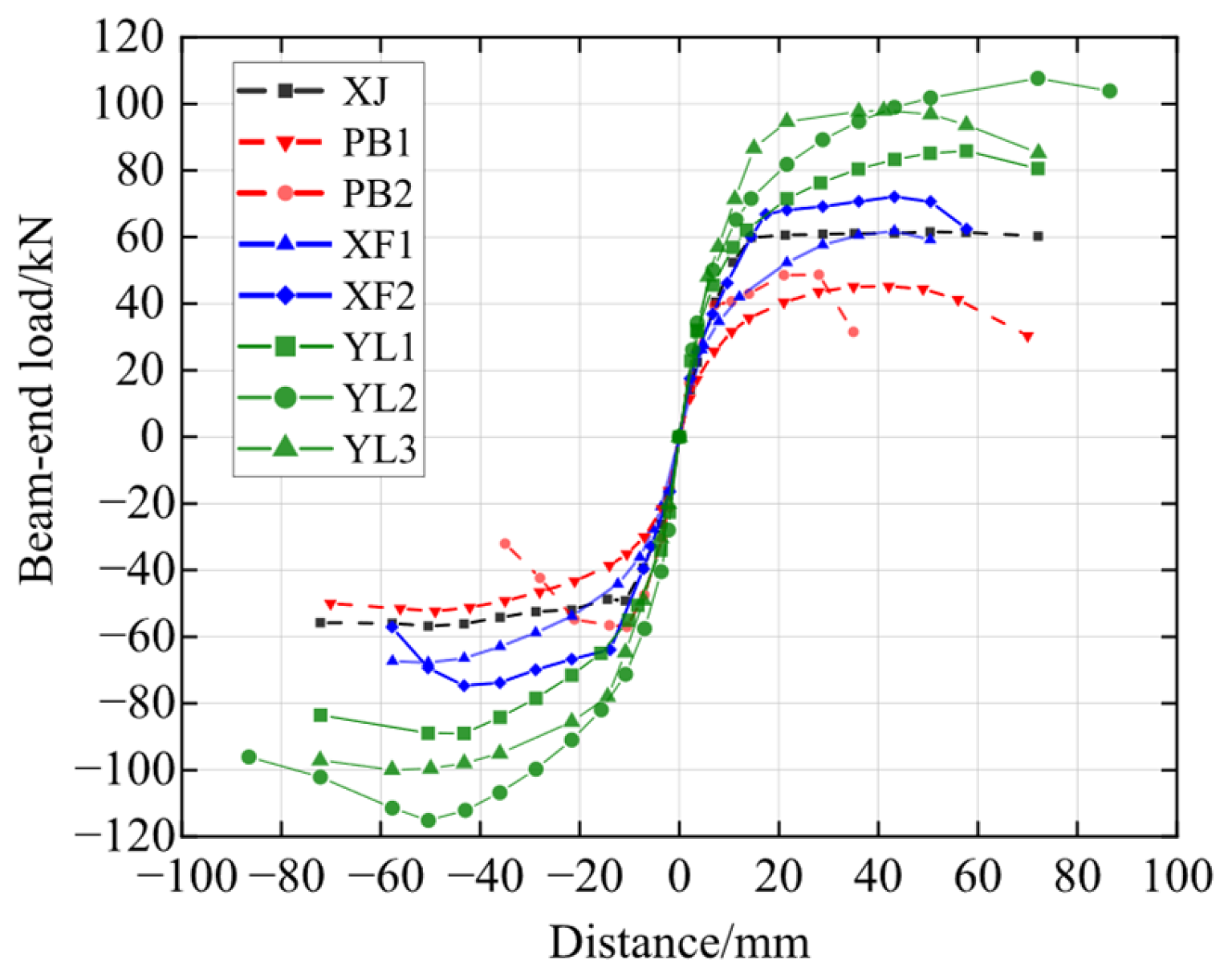
- The non-optimized joints of XJ, PB1, and PB2 exhibited marginally lower peak load-bearing capacities than the cast-in situ concrete (RC) joints. PB1 and PB2 had 20.49% and 13.93% lower peak load-bearing capacity than XJ. However, their strength-to-yield ratios (1.20 and 1.13, respectively) exceeded that of the cast-in situ joint (1.10).
- (2)
- The analysis of PB1, XF1, and YL1 indicated the effectiveness of the SSFRC joint optimization. Increasing the end-plate thickness improved the bearing capacity by 35.41%, whereas employing prestressed tendon reinforcement achieved an 82.29% improvement in load-bearing performance.
- (3)
- The evaluation of PB2, XF2, and YL3 demonstrated the critical influence of the grout’s strength on the SSFRC joints with stiffening ribs. The grout strength affected the bonding performance between precast beams and steel sleeves and the subsequent joint failure mode. Utilizing C80-grade grout resulted in a 39.05% higher bearing capacity. Applying prestressing increased the bearing capacity by 88.57%.
- (4)
- A comparison of YL1 and YL2 highlighted the impact of prestressing tendons. The dual symmetrical tendon configuration of YL2 provided 27.27% higher bearing capacity than the central single-tendon configuration of YL1. This improvement was attributed to the longer distance between the prestressed tendons and the section’s neutral axis, enhancing structural moment capacity.
- (1)
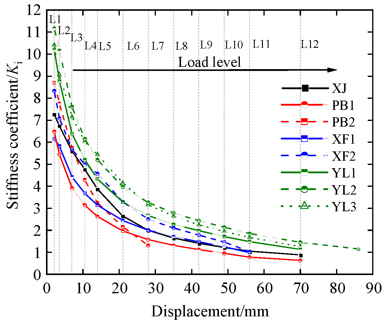
- During the initial loading phase, the prestressed specimens YL1, YL2, and YL3 demonstrated the highest initial stiffness, exhibiting stiffness improvements of 40.49%, 54.01%, and 43.53%, respectively, compared to the cast-in situ joint specimen. Specimens with stiffening ribs (PB2, XF2) had 23.67% and 17.74% higher initial stiffness than the cast-in situ joint specimen. These experimental results indicated that prestressing tendons and stiffening ribs substantially increased the initial structural stiffness, with the former contributing the most.
- (2)
- All specimens exhibited marked stiffness degradation during advanced loading stages, indicating progressive accumulation of irreversible plastic damage. Prestressed joints (YL1, YL2, YL3) demonstrated higher residual stiffness than conventional cast-in situ joints due to the self-centering effect of tendons, thus reducing the proportion of plastic deformation to total displacement. Consequently, PSFRC joints showed enhanced stiffness retention under equivalent displacement cycles. Although specimen XF1 had lower initial stiffness, it marginally exceeded XJ in later stages, demonstrating that optimized SSFRC joints improve resistance to stiffness degradation mechanisms.
- (1)
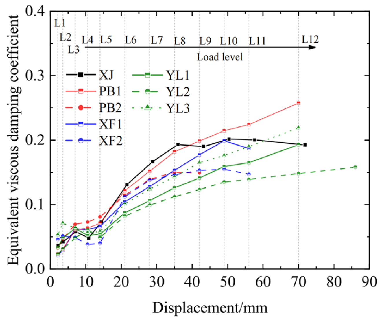
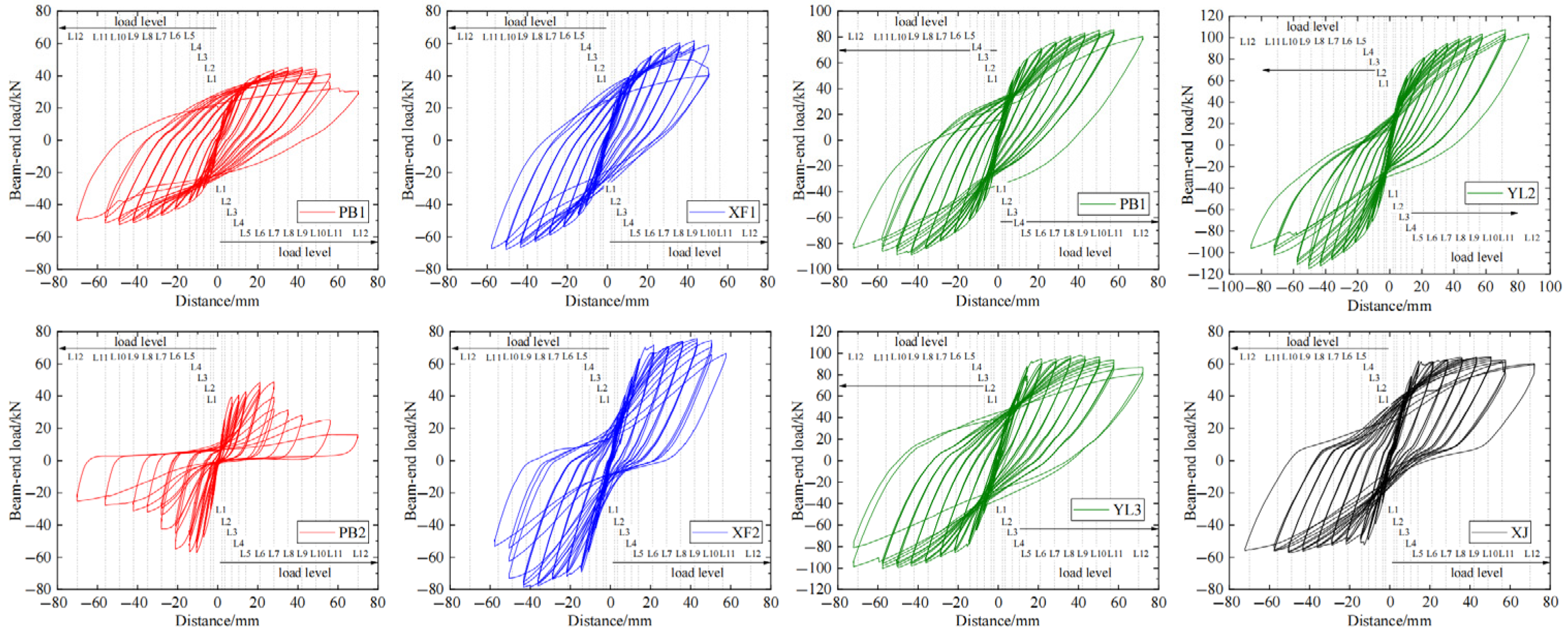
- The cast-in situ joint XJ and the precast specimens exhibited different energy dissipation characteristics. During the mid-loading phase (20 mm–40 mm displacement range), the cast-in situ joint had higher energy dissipation capacity than its precast counterpart. However, during advanced loading stages, specimens PB1 and YL3 exhibited hysteretic energy dissipation exceeding that of the XJ benchmark specimen.
- (2)
- Although prestressing increased the joint load-bearing capacity and stiffness of YL1, YL2, and YL3, it negatively impacted energy dissipation capacity. This result highlights the necessity of stiffening ribs in PSFRC joints. Specimen YL3 with the stiffening ribs had 13.47% and 47.97% higher energy dissipation capacity than YL1 and YL2, respectively.
- (1)
- The cast-in situ concrete joint specimen XJ exhibited the highest ductility coefficient (5.39). SSFRC joint specimen PB2 had the lowest value (3.09), attributable to grout failure, which compromised the bond between the precast beams and steel sleeves, resulting in rapid post-peak deterioration. This finding underscores the importance of grout strength in SSFRC joint design to prevent premature failure. The precast joints exhibit lower ductility coefficients than the cast-in-place joint. This is primarily due to the superior integrity of cast-in situ specimens. After the yielding of reinforcement, the plastic hinge can undergo significant plastic rotation. In contrast, precast specimens possess multiple connecting components at their joint regions. This results in less smooth force transfer compared to cast-in situ structures. Consequently, after reaching the peak load-carrying capacity, the strength deteriorates more rapidly, leading to somewhat inferior ductility.
- (2)
- Comparative analysis of the PSFRC and SSFRC joint specimens revealed the significant influence of the prestressed tendon configuration on joint ductility. The central single-strand tendon configuration provided limited ductility enhancement, with specimen YL1 showing a 3.53% improvement over XF1. Conversely, the symmetrical two-strand configuration substantially improved ductility. Specimen YL2 had an 18.75% higher ductility coefficient than YL1.
- (3)
- The stiffening ribs substantially increased structural ductility. For the PSFRC joints, specimen YL3 exhibited 26.14% higher ductility than YL1. Similarly, SSFRC joint XF2 showed 16.76% ductility improvement over XF1. These results indicated that the stiffening ribs significantly increased the ductility of the prestressed structures, demonstrating they are critical PSFRC components requiring careful design consideration.
- (4)
- Comparing specimens PB2 (C60 grout, μ = 3.09) and XF2 (C80 grout, μ = 3.97) reveals grout strength’s ductility impact. Prior tests with PB1/XF1 confirm that end-plate thickness variations (present in PB2/XF2) minimally affect ductility. The 28.47% higher ductility in XF2 demonstrates C80 grout’s efficacy. Mechanistically, higher-strength grout improves steel sleeve-to-beam bonding, enabling the efficient transfer of beam-end bending stresses to the sleeve. This synergy optimizes material utilization, enhancing joint capacity and ductility.
3.3. Evolution of the Prestressing Force
- (1)
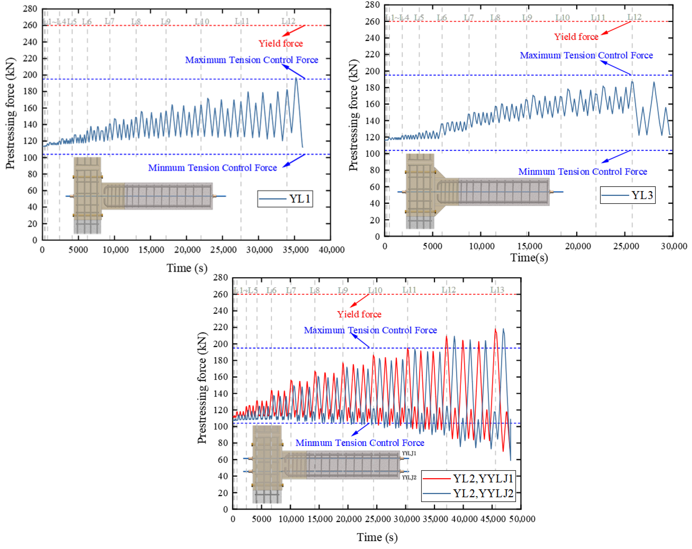
- Comparative analysis of YL1 and YL3 demonstrates that both specimens exhibited a minimal loss in the prestressing force during loading, with the prestressed tendons functioning effectively within their elastic working range. Although the curves of both specimens exhibited fluctuations, their characteristics differed. (A) The prestressing force curve of specimen YL1 exhibited higher amplitudes and was more symmetrical. (B) The curve of specimen YL3 exhibited lower amplitudes and an upward trend in proportion to the load. The reasons were as follows: (A) The absence of stiffening ribs in YL1 resulted in lower joint stiffness and larger beam-end rotations at the same load, increasing the elongation of the prestressed tendons and the amplitude of YL1’s curve. (B) The stiffening ribs in YL3 improved the rotational stiffness. Joint deformation occurred predominantly at the interface between the precast beam and steel sleeve. This configuration caused higher plastic deformation during loading, generating significant residual deformation. Consequently, YL3’s curve exhibited an increasing trend.
- (2)
- YL1 and YL2 had different joint configurations, specifically the prestressed tendon configuration. The two symmetrical tendon bundles in YL2 enhanced force participation at the beam ends during loading. At a displacement of 72 mm (12 L), the prestressing force was 210 kN for YL2 and 190 kN for YL1 under equivalent loading conditions. The symmetrical tendon configuration improved the prestressing efficiency and adversely affected prestress loss. Under cyclic loading, YL2 exhibited an initial prestressing force of 110 kN and a final value of 60 kN, representing a 45.45% loss.
4. Moment–Rotation Relationship Curve Analysis of Joints
4.1. Differences in Curves for Different Joint Types
- (1)
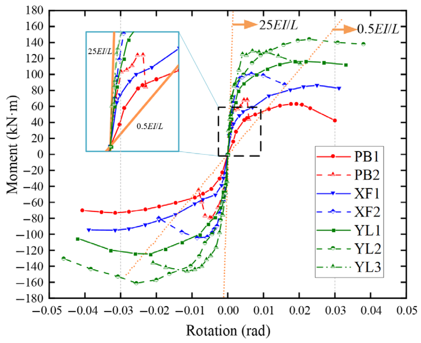
- The rigid and pinned connection boundaries were determined according to the Eurocode. All specimens exhibited initial rotational stiffness between rigid and pinned connections, indicating semi-rigid connections.
- (2)
- The initial rotational stiffness of the joints exhibited a trend similar to the initial stiffness of the joint skeleton curve discussed earlier. Specimens PB1 and XF1 without stiffeners or prestressed tendons demonstrated lower initial rotational stiffness, approaching the pinned connection boundary. In contrast, specimens with stiffeners and prestressed tendons exhibited higher initial rotational stiffness, approaching the rigid connection boundary.
- (1)
- Material damage is neglected, assuming ideal elastic–plastic material behavior;
- (2)
- Coupling effects between components are disregarded, assuming mutual independence among components;
- (3)
- The component-based method ignores complex three-dimensional effects, post-buckling behaviors, residual stresses, specific manufacturing imperfections, and highly non-uniform stress distributions.
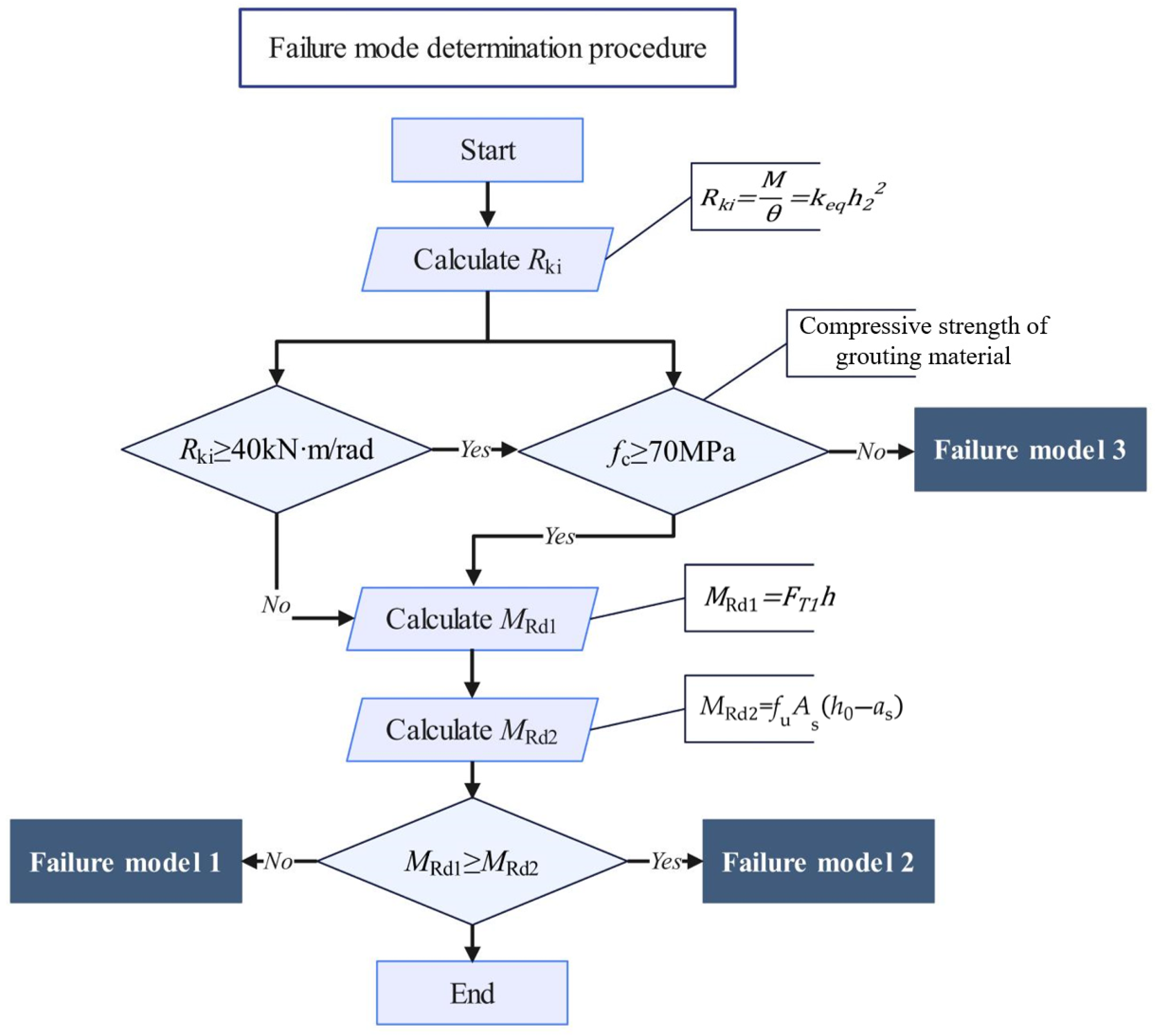
- (1)
- Calculate the initial rotational stiffness Rki of the SSFRC and PSFRC joints.
- (2)
- Determine the flexural capacity Mrd of the SSFRC and PSFRC joints.
- (3)
- The yield moment My of the joint was calculated using Equation (1) based on the design standard. The rotational stiffness had the initial value Rki when the moment at the joint was less than My.
- (4)
- The rotational stiffness was adjusted using the following expression when the bending moment affecting the joint exceeded the yield moment My but remained below the flexural capacity Mrd:
- (5)
- The linear hardening phase was entered when the bending moment at the joint exceeded the flexural capacity Mrd. The post-hardening stiffness kp was 0.02 Rki.
4.2. Theoretical Calculation of Initial Rotational Stiffness of Structural Joints
4.2.1. Flexural and Shear Stiffness of the Joint Core Zone
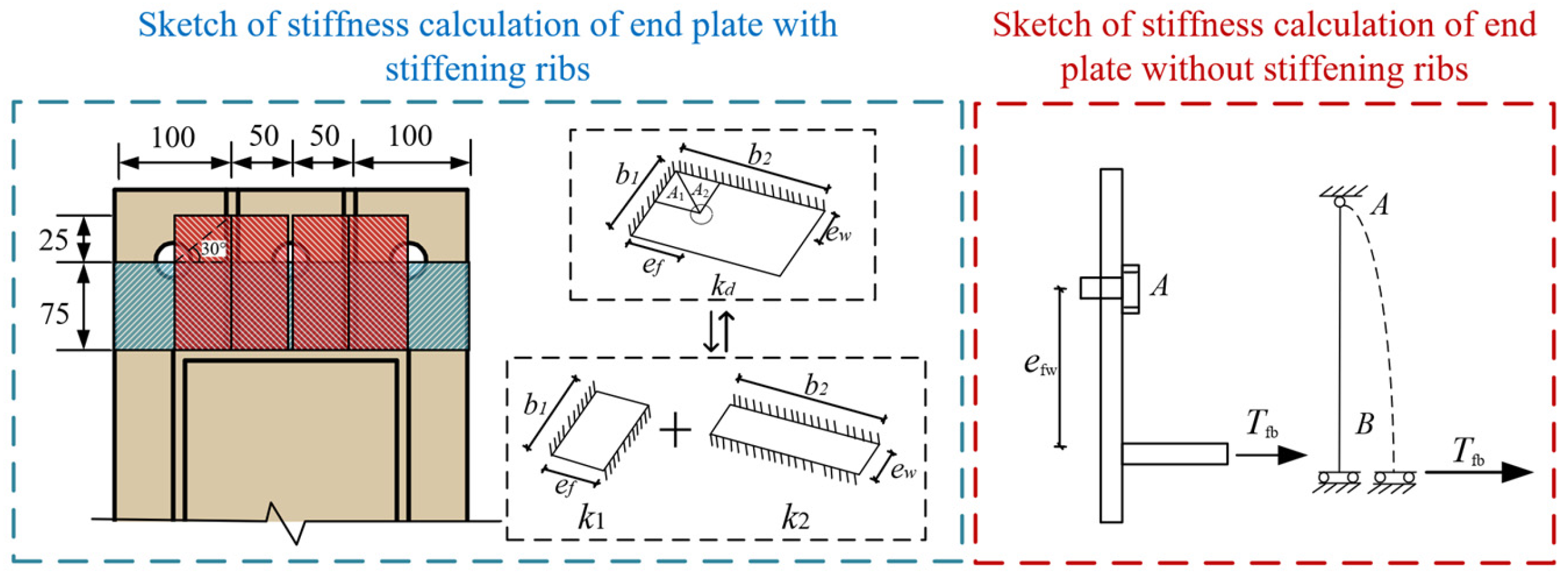
4.2.2. Calculation of Tensile Stiffness of End Plates in Steel Sleeve Beams
- (1)
- Calculation of tensile stiffness of unstiffened end plates
- (2)
- Calculation of tensile stiffness of stiffened end plates in steel sleeve beams
4.2.3. Calculation of Tensile Stiffness of High-Strength Bolts
4.2.4. Calculation of Tensile Stiffness of Prestressed Tendons
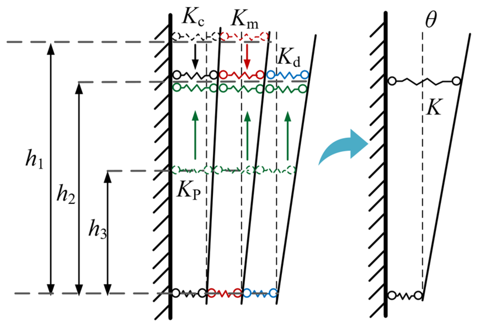
4.2.5. Analysis of Joint Rotational Stiffness
4.3. Theoretical Calculation of the Structural Joint’s Flexural Capacity
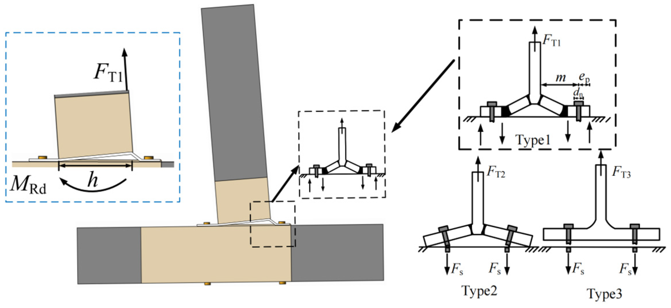
4.3.1. Flexural Load Capacity During the Failure of the Beam’s Steel Sleeve End Plate
4.3.2. Flexural Load Capacity During the Failure of the Prefabricated Beam
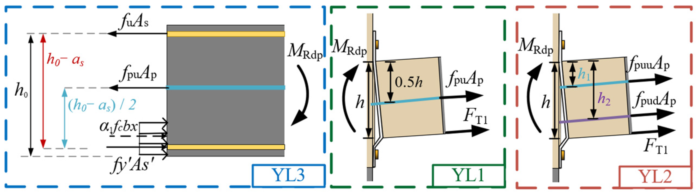
4.3.3. Flexural Load Capacity During the Failure of the Prefabricated Beam’s Variable Cross-Section
4.3.4. The Flexural Capacity Provided by the Prestressed Tendons
4.3.5. The Flexural Capacity of Specimens
- (1)
- The Type 3 failure mode must first be isolated from the three categories, as it constitutes brittle failure and must be avoided.
- (2)
- Secondly, distinguish between the Type 1 and Type 2 failure modes. Both failure modes are acceptable and belong to ductile failure. Before failure occurs, there is an obvious premonitory indication.
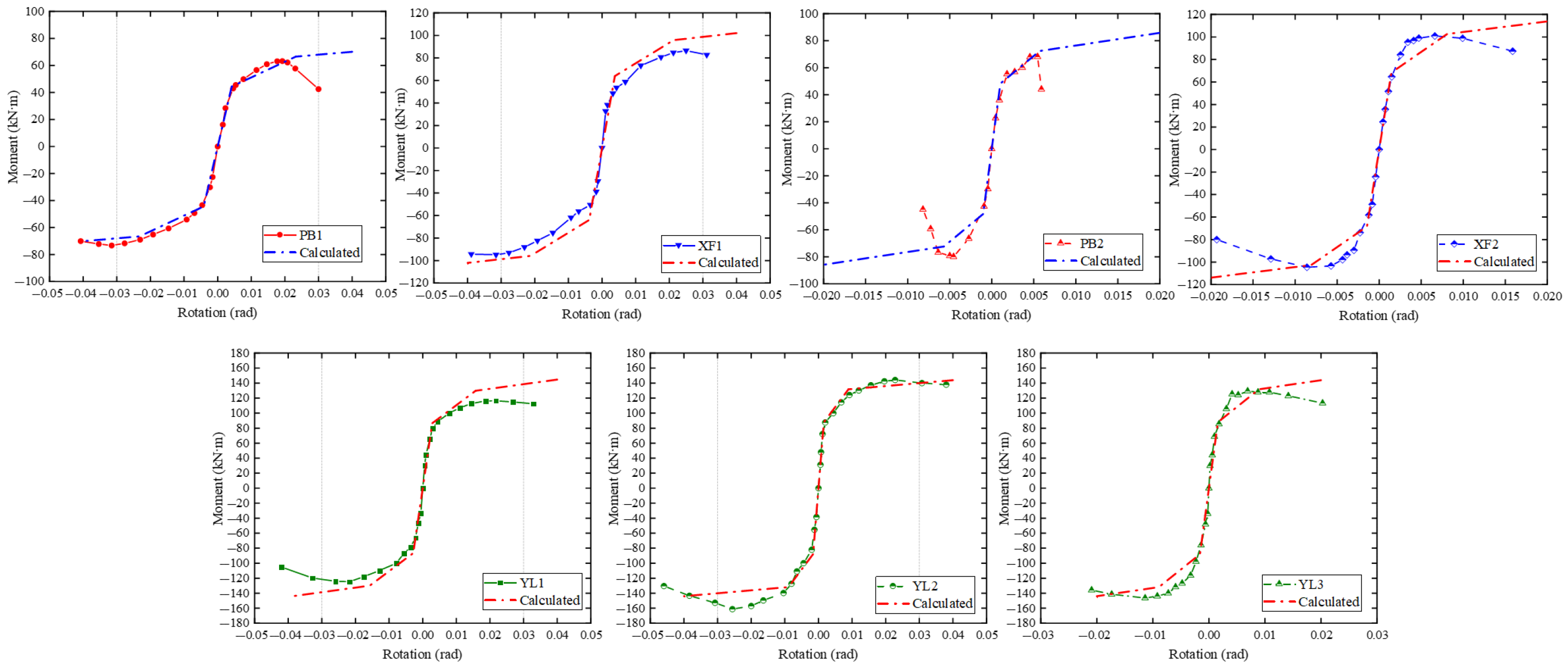
4.4. Curve Fitting Results of Moment–Rotation Relationship
5. Discussion
- (1)
- Firstly, discussions regarding the dimensions of components and variables involved in this paper: as the theoretical derivations were based on experimental studies, although theoretical calculation formulas were derived, their applicability to structures of all sizes and material strengths still requires verification through numerical simulations or supplementary tests. Moreover, the derived formulas incorporate certain assumptions and boundary conditions, such as the thickness of end plates in beam steel sleeves. Generally, thicker end plates increase bearing capacity; however, in this study, when end plate thickness exceeds a specific threshold, the failure plane shifts to the precast beam. Further increasing plate thickness under such conditions proves ineffective and uneconomical. Boundary conditions for plate thickness can be determined using the failure mode discrimination formula provided earlier, with the engineering practice limiting thickness to ≤30 mm.
- (2)
- Adopting the component method recommended by EC3 is a simplified method for deriving joint rotational stiffness. When simulating the refined nonlinear behavior of components and realistic progressive damage evolution processes under strong earthquakes, its modeling limitations are evident [49]. It simplifies complex physical interactions between components but struggles to precisely describe microscopic locations and physical mechanisms of damage.
- (3)
- Prestressing inherently limits energy dissipation due to non-yielding tendons with minimal plastic deformation capacity. While providing beneficial self-centering, this results in slender hysteresis loops with a reduced enclosed area (representing energy dissipated via inelastic processes). Optimization aims to augment energy dissipation without compromising stiffness/strength. Below are some effective methods considered by the authors: (a) Employing dedicated energy dissipation devices: As implemented with stiffeners in this paper, such devices impart energy dissipation capacity to the structure without altering its inherent characteristics. (b) Adopting shape memory alloys (SMAs): Utilizing the superplastic effect of SMAs. After unloading within a specific strain range, deformation can be almost fully recovered (superior self-centering capacity), while considerable energy is dissipated through phase transformation during cyclic loading (full hysteresis loops).
- (4)
- For the design and practical construction scenarios of the novel prefabricated frame structure proposed in this paper, C80 grout and stiffeners are critical elements. However, both indeed present generalizability concerns. For grout, increasing the strength grade typically reduces its fluidity. Thus, this paper recommends adopting pressure grouting methods in practical construction. Regarding stiffeners, while their presence provides excellent energy dissipation capacity, they cause difficulties in floor slab installation during construction. In subsequent research, the authors will further investigate floor slabs suitable for this joint type, such as precast notched slabs.
6. Conclusions
- (1)
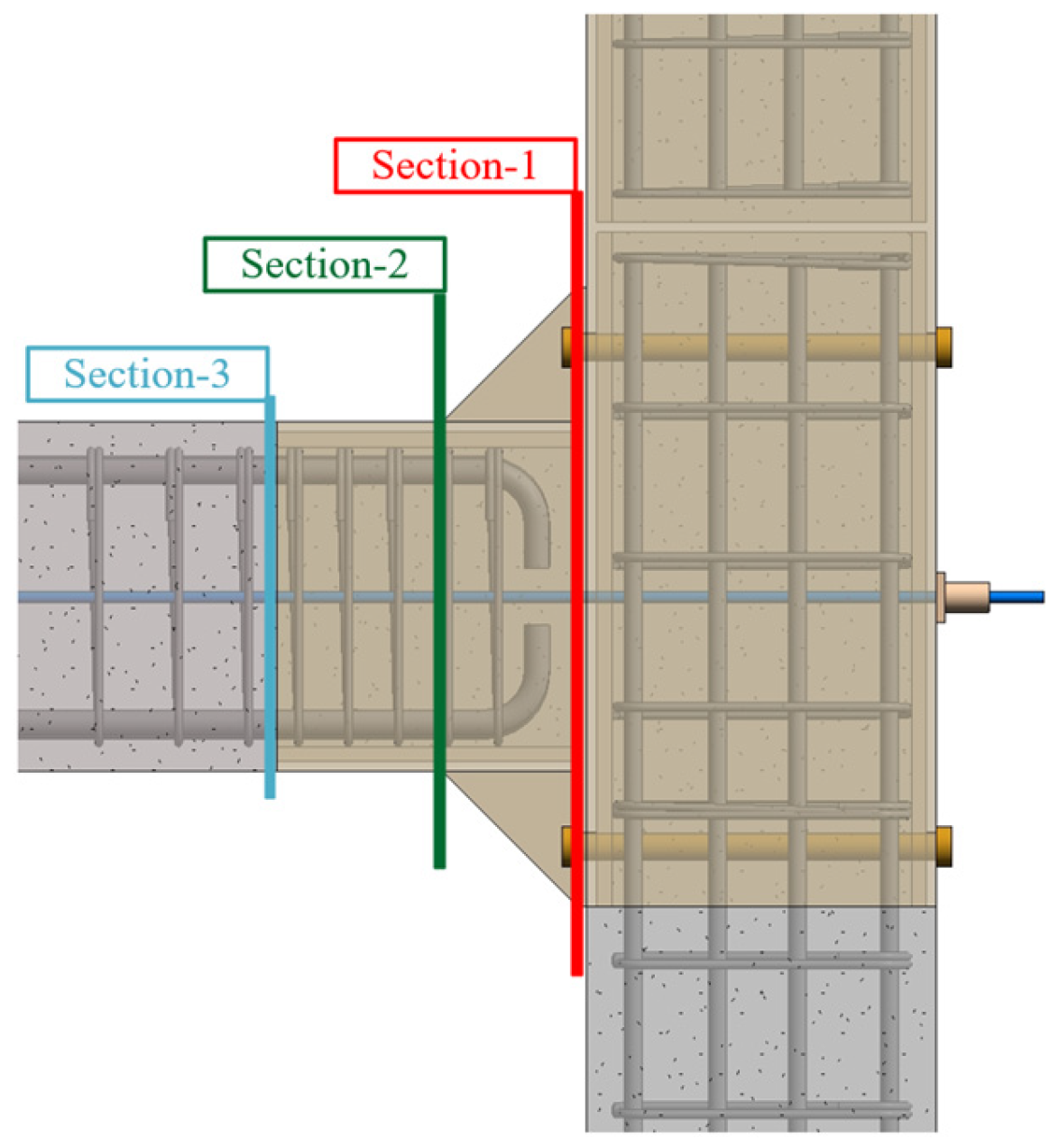
- All specimens exhibited failure at the beam end in both rounds of tests, which is consistent with the design concept of strong columns and weak beams. The seismic performance test indicated three failure modes: (1) failure of the beam sleeve’s end plate, (2) failure of the variable cross-section of the prefabricated beam caused by the slip of the interface between the steel plate and the prefabricated beam, and (3) failure of prefabricated beams at the connection with the steel sleeves. Differences in the stiffnesses of the beam–steel sleeve–end-plate connections and in the bond between the beam–steel sleeve and the precast girder caused different failure modes. The third type of failure mode needs to be avoided.
- (2)
- Increasing the end-plate thickness of the SSFRC joints improved the load-bearing capacity and initial stiffness significantly. Specimen XF1 demonstrated a 35.41% higher ultimate load capacity and a 32.64% higher initial stiffness than specimen PB1. Specimens with C80-grade grout exhibited a 39.05% higher load capacity than those with lower-grade materials. Specimen PB2, constructed with C60-grade grout, failed prematurely due to an inadequate moment and shear transfer between the steel sleeve and precast beam. Specimen XF2 had a 219.08% higher initial stiffness than XF1, confirming the efficacy of stiffeners in enhancing joint rigidity.
- (3)
- Prestressing tendon configuration significantly affected PSFRC joint load capacity. YL2 (symmetrical double bundles) had 27.27% higher ultimate load than YL1 (single central bundle). While prestressing enhanced load capacity and stiffness, it reduced energy dissipation. Stiffeners proved critical: YL3 exhibited 13.47% and 47.97% higher energy dissipation than YL1 and YL2, respectively, plus 26.14% greater ductility coefficient than YL1.
- (4)
- The component method of Eurocode 3 was utilized to develop an analytical model for calculating the joint’s initial rotational stiffness, and a design equation for this parameter was subsequently derived. The moment resistance of the joints was systematically evaluated under different failure modes. Close agreement between theoretical and experimental results was demonstrated, providing empirical references for practical engineering applications.
- (5)
- This paper recommends a minimum grout strength of C80 and minimum stiffener dimensions of 100 mm × 100 mm. The use of higher-strength C80 grout can better bond the steel sleeve and precast beam together, so that the stress generated by the bending moment at the beam end can be better transmitted to the beam steel sleeve.
Author Contributions
Funding
Data Availability Statement
Conflicts of Interest
References
- Dong, Y.; Qin, T.Y.; Zhou, S.Y.; Huang, L.; Bo, R.; Guo, H.B.; Yin, X.Z. Comparative Whole Building Life Cycle Assessment of Energy Saving and Carbon Reduction Performance of Reinforced Concrete and Timber Stadiums-A Case Study in China. Sustainability 2020, 12, 1566. [Google Scholar] [CrossRef]
- Guo, J.; Zhang, X.W.; Cui, Y.H. Estimation of Fatigue Parameters and Life Prediction for Orthotropic Steel Deck Based on Reverse Markov Theory. J. Struct. Eng. 2025, 151, 04025037. [Google Scholar] [CrossRef]
- Nie, G.; Wang, W.; Zhang, C.X.; Zhi, X.D.; Liu, K. Seismic evaluation of isolation performance on single layer cylindrical reticulated shells supported along four sides. Eng. Struct. 2024, 301, 117279. [Google Scholar] [CrossRef]
- Yao, C.H.; Liu, J.P.; Li, J.; Chen, Y.F. Shear behavior of thin-walled concrete-filled steel tubular columns. Eng. Struct. 2024, 314, 118357. [Google Scholar] [CrossRef]
- Zhou, H.M.; Shao, X.Y.; Zhang, J.W.; Yao, H.C.; Liu, Y.H.; Tan, P.; Chen, Y.Y.; Xu, L.; Zhang, Y.; Gong, W. Real-time hybrid model test to replicate high-rise building resonant vibration under wind loads. Thin-Walled Struct. 2024, 197, 111559. [Google Scholar]
- Lacey, A.W.; Chen, W.; Hao, H.; Bi, K. Structural response of modular buildings–An overview. J. Build. Eng. 2018, 16, 45–56. [Google Scholar] [CrossRef]
- Ferdous, W.; Bai, Y.; Ngo, T.D.; Manalo, A.; Mendis, P. New advancements, challenges and opportunities of multi-storey modular buildings–A state-of-the-art review. Eng. Struct. 2019, 183, 883–893. [Google Scholar] [CrossRef]
- Aghasizadeh, S.; Tabadkani, A.; Hajirasouli, A. Environmental and economic performance of prefabricated construction: A review. Environ. Impact Assess. Rev. 2022, 97, 106897. [Google Scholar] [CrossRef]
- Wen, Y.F. Research on the intelligent construction of prefabricated building and personnel training based on BIM5D. J. Intell. Fuzzy Syst. 2021, 40, 8033–8041. [Google Scholar] [CrossRef]
- Wang, Y.L.; Li, Y.L.; Zhuang, J.X. Research on the green development path of prefabricated building industry based on intelligent technology. Eng. Constr. Archit. Manag. 2024; ahead-of-print. [Google Scholar] [CrossRef]
- Bao, Y.X.; Xiang, C.Y. Integration of BIPV technology with modular prefabricated building-A review. J. Build. Eng. 2025, 102, 111940. [Google Scholar] [CrossRef]
- Zhang, Z.W.; Li, D.; Wang, H.J.; Qian, H.L.; Fang, W.Q.; Jing, X.F.; Fan, F. Study of mechanical properties of a novel column-beam-column prefabricated steel frame joint. Adv. Steel Constr. 2024, 20, 330–344. [Google Scholar]
- Yang, H.; Wu, J.; Guo, Z. Experimental research on seismic performance of dry-wet combined precast concrete beam-to-column connections. J. Build. Eng. 2024, 91, 109716. [Google Scholar] [CrossRef]
- Ghayeb, H.H.; Sulong, N.H.R.; Razak, H.A.; Mo, K.H.; Ismail, Z.; Hashim, H.; Gordan, M. A review of the seismic performance behaviour of hybrid precast beam-to-column connections. Arch. Civ. Mech. Eng. 2022, 23, 35. [Google Scholar] [CrossRef]
- Ren, H.H.; Bahrami, A.; Cehlin, M.; Wallhagen, M. A state-of-the-art review on connection systems, rolling shear performance, and sustainability assessment of cross-laminated timber. Eng. Struct. 2024, 317, 118552. [Google Scholar] [CrossRef]
- Priestley, M.J.N.; Sritharan, S.; Conley, J.R.; Pampanin, S. Preliminary results and conclusions from the PRESSS five-story precast concrete test building. PCI J. 1999, 44, 42. [Google Scholar] [CrossRef]
- Priestley, M.J.N. Overview of PRESSS Research Program. PCI J. 1991, 36, 50–57. [Google Scholar] [CrossRef]
- Priestley, M.J.N.; Tao, J.R. Seismic Response of Precast Prestressed Concrete Frames with Partially Deboned Tendons. PCI J. 1993, 38, 58–69. [Google Scholar] [CrossRef]
- Liu, B.K.; Song, M.R.; Jiang, Y.Q.; Huang, S.J.; Zhou, A. Experimental study on seismic performance of post-tensioned precast prestressed concrete frame. J. Build. Struct. 2011, 32, 24–32. [Google Scholar]
- Chong, X.; Meng, S.P.; Pan, Q.J.; Zhang, L.Z. Research on seismic behavior of partially unbonded precast prestressed concrete frames and beam-column subassemblies. J. Earthq. Eng. Eng. Vib. 2007, 4, 55–60. [Google Scholar]
- Cai, X.N.; Meng, S.P.; Sun, W.W. Experimental study on behaviors of beam-column connections for self-centering post-tensioned precast frame. China Civ. Eng. J. 2012, 45, 29–45. [Google Scholar]
- Reinhardt, H.W. Demountable concrete structures—An energy and material saving building concept. Int. J. Sustain. Mater. Struct. Syst. 2012, 1, 18. [Google Scholar] [CrossRef]
- Aninthaneni, P.K.; Dhakal, R.P.; Marshall, J.; Bothar, J. Experimental investigation of “dry” jointed precast concrete frame sub-assemblies with steel angle and tube connections. Build. Earthq. Eng. 2020, 18, 3659–3681. [Google Scholar] [CrossRef]
- Wang, K.H.; Li, Z.Y.; Rong, B.; Zhang, R.Y.; Sun, Y.L.; Zhang, W.C.; Wu, H.L. Experimental and numerical research on hysteretic behavior of bolted end-plate connections. Structures 2025, 73, 108397. [Google Scholar] [CrossRef]
- Morgen, B.G.; Kurama, Y.C.; Asce, M. Seismic Design of Friction-Damped Precast Concrete Frame Structures. J. Struct. Eng. 2007, 133, 1501–1511. [Google Scholar] [CrossRef]
- San, B.B.; Xu, S.Z.; Shan, Z.W.; Chen, W.; Daniel, T.W.L. Investigation on probability model of bending moment-rotation relationship for bolt-ball joints. J. Constr. Steel Res. 2025, 226, 109193. [Google Scholar] [CrossRef]
- Park, S.; Clayton, P.; Williamson, E.B.; Helwig, T.A.; Engelhardt, M.D. Cyclic moment-rotation model for bolted double-angle connections with composite floor systems. J. Build. Eng. 2024, 96, 110460. [Google Scholar] [CrossRef]
- Ma, K.; Ye, X.H.; Wu, R.Y.; Yu, H.F.; Wang, Z.; Jin, T.J.; Ji, W.J.; Zhao, Y. Seismic behavior and initial rotational stiffness of beam-to-column composite connection in steel frame. Structures 2024, 62, 106069. [Google Scholar] [CrossRef]
- BS EN 1993-1-8; Eurocode 3: Design of Steel Structures-Part 1–8: Design of Joints. European Committee for Standardization: Brussels, Belgium, 2004.
- Xue, H.Y.; Ashour, A.; Ge, W.J.; Cao, D.F.; Sun, C.Z.; Cao, S.Q. Seismic response of prestressed precast reinforced concrete beam-column joints assembled by steel sleeves. Eng. Struct. 2023, 276, 115328. [Google Scholar] [CrossRef]
- Liu, J.Q.; Cao, D.F.; Wang, K.; Zhou, Y.L.; Xue, H.Y. Study on seismic performance of prestressed fabricated reinforced concrete frame structure assembled by steel sleeves. Eng. Struct. 2025, 322, 119222. [Google Scholar] [CrossRef]
- Wang, X.; Wan, P.P.; Zhu, Z.Y.; Wang, K.; Cao, D.F.; Yang, Y.; Yang, D.D.; Zhang, L.F. Research on seismic performance of new prestressed precast beam-column sleeve concrete frame joints. Structures 2024, 61, 105954. [Google Scholar] [CrossRef]
- GB/T 50152-2012; Standard for Test Method of Concrete Structures. China Architecture and Building Press: Beijing, China, 2012.
- GB/T50448-2008; Code for Application Technique of Cementitious Grout. China Planning Press: Beijing, China, 2008.
- GB/T 50081-2019; Standard for Test Methods of Concrete Physical and Mechanical Properties. China Architecture and Building Press: Beijing, China, 2019.
- GB/T 228.1-2021; Metallic materials-Tensile Testing-Part 1:Method of Test at Room Temperature. Standards Press of China: Beijing, China, 2021.
- JGJ/T 101-2015; Specification of Seismic Test of Buildings. China Architecture and Building Press: Beijing, China, 2015.
- Bagheri, M.; Jamkhaneh, M.E.; Samali, B. Effect of Seismic Soil-Pile-Structure Interaction on Mid- and High-Rise Steel Buildings Resting on a Group of Pile Foundations. Int. J. Geomech. 2018, 18, 04018103.1–04018103.27. [Google Scholar] [CrossRef]
- Kulkarni, S.A.; Li, B.; Yip, W.K. Finite element analysis of precast hybrid-steel concrete joints under cyclic loading. J. Constr. Steel Res. 2008, 64, 190–201. [Google Scholar] [CrossRef]
- Ghayeb, H.H.; Razak, H.A.; Sulong, R.N.R. Seismic performance of innovative hybrid precast reinforced concrete beam-to-column joints. Eng. Struct. 2020, 202, 109886. [Google Scholar] [CrossRef]
- Guo, Z.H.; Shi, X.D. Reinforced Concrete Theory and Analyze; Tsinghua University Press: Beijing, China, 2006. [Google Scholar]
- Zhao, J.H.; Fan, J.H.; Gao, W.Q. Calculation model for initial rotational stiffness of steel beam to concrete-filled steel tube column joints with extended end-plate. J. Build. Struct. 2021, 42, 103–111. [Google Scholar]
- Castro, J.M.; Elghazouli, A.Y.; Izzuddin, B.A. Modelling of the panel zone in steel and composite moment frames. Eng. Struct. 2005, 27, 129–144. [Google Scholar] [CrossRef]
- Kim, K.-D.; Engelhardt, M.D. Monotonic and cyclic loading models for panel zones in steel moment frames. J. Constr. Steel Res. 2002, 58, 605–635. [Google Scholar] [CrossRef]
- Shi, G.; Shi, Y.J.; Wang, Y.Q. Calculation method on Moment-Rotation curves of Beam-to-column semirigid end-plate connections. Eng. Mech. 2006, 23, 67–73. [Google Scholar] [CrossRef]
- Pampanin, S. PRESSS Design Handbook; New Zealand Concrete Society: Wellington, New Zealand, 2010. [Google Scholar]
- GB 50010-2010; Code for design of concrete structures. China Architecture and Building Press: Beijing, China, 2010.
- Lv, Z.T. Modern Prestressed Structure System and Design Method; Phoenix Publishing Press: Nanjing, China, 2010. [Google Scholar]
- Asgari, A.; Bagheri, M.; Hadizadeh, M. Advanced seismic analysis of soil-foundation-structure interaction for shallow and pile foundations in saturated and dry deposits: Insights from 3D parallel finite element modeling. Structures 2024, 69, 107503. [Google Scholar] [CrossRef]

| Specimen | Joint Type | Prestressing Tendon | Steel Plate Thickness (mm) | Length of Stiffening Rib (mm) | Grade of High-Strength Grouts |
|---|---|---|---|---|---|
| PB1 | SSFRC | / | 10 | / | C60 |
| PB2 | SSFRC | / | 10 | 100 | C60 |
| XF1 | SSFRC | / | 12 | / | C80 |
| XF2 | SSFRC | / | 12 | 135 | C80 |
| YL1 | PSFRC | 1 × 0.45 fptk | 12 | / | C80 |
| YL2 | PSFRC | 2 × 0.45 fptk | 12 | / | C80 |
| YL3 | PSFRC | 1 × 0.45 fptk | 12 | 135 | C80 |
| XJ | cast-in-place | / | / | / | / |
| Specimen | Cube Compressive Strength (MPa) | Axial Compressive Strength (MPa) | Modulus of Elasticity (GPa) |
|---|---|---|---|
| C40 | 48.90 | 37.10 | 34.36 |
| Specimen | Cube Compressive Strength (MPa) | Paste Fluidity (mm) |
|---|---|---|
| C60 | 67.30 | 334 |
| C80 | 85.50 | 322 |
| Components | Diameter and Thickness (mm) | Yield Strength (MPa) | Ultimate Strength (MPa) | Elastic Modulus (GPa) |
|---|---|---|---|---|
| M27 bolt | 27 | 935.20 | 1035.00 | 206.10 |
| Steel plate | 10 | 401.00 | 510.00 | 205.00 |
| Steel bars | 8 | 442.20 | 541.30 | 204.00 |
| 16 | 445.00 | 533.40 | 203.20 | |
| 18 | 436.00 | 522.00 | 201.50 |
| Specimen | Load Direction | Py (kN) | Pu (kN) | Pu/Py | Average (Pu/Py) |
|---|---|---|---|---|---|
| XJ | Positive | 56.04 | 62.54 | 1.11 | 1.10 |
| Negative | 55.78 | 60.87 | 1.09 | ||
| PB1 | Positive | 38.20 | 46.14 | 1.21 | 1.20 |
| Negative | 42.93 | 51.35 | 1.20 | ||
| PB2 | Positive | 43.09 | 49.68 | 1.15 | 1.13 |
| Negative | 49.53 | 55.07 | 1.11 | ||
| XF1 | Positive | 51.33 | 61.80 | 1.20 | 1.21 |
| Negative | 55.57 | 67.81 | 1.22 | ||
| XF2 | Positive | 65.36 | 72.11 | 1.10 | 1.11 |
| Negative | 66.61 | 74.69 | 1.12 | ||
| YL1 | Positive | 71.5 | 85.8 | 1.20 | 1.21 |
| Negative | 72.2 | 89.1 | 1.23 | ||
| YL2 | Positive | 89.4 | 107.6 | 1.20 | 1.21 |
| Negative | 94.1 | 115.2 | 1.22 | ||
| YL3 | Positive | 89.4 | 98.0 | 1.09 | 1.13 |
| Negative | 85.7 | 100.3 | 1.17 |
| Specimen | Load Direction | Δy (mm) | Δu (mm) | μ∆ | Average (μ∆) |
|---|---|---|---|---|---|
| PB1 | Positive | 16.71 | 59.77 | 3.58 | 3.53 |
| Negative | 20.46 | 70.08 | 3.48 | ||
| PB2 | Positive | 9.85 | 30.06 | 3.05 | 3.09 |
| Negative | 7.83 | 24.56 | 3.13 | ||
| XF1 | Positive | 16.87 | 57.70 | 3.42 | 3.40 |
| Negative | 17.33 | 58.58 | 3.38 | ||
| XF2 | Positive | 14.70 | 57.76 | 3.92 | 3.97 |
| Negative | 14.13 | 56.75 | 4.01 | ||
| YL1 | Positive | 20.02 | 72.32 | 3.61 | 3.52 |
| Negative | 21.13 | 72.25 | 3.42 | ||
| YL2 | Positive | 21.85 | 87.94 | 4.02 | 4.18 |
| Negative | 20.06 | 87.10 | 4.34 | ||
| YL3 | Positive | 15.71 | 72.20 | 4.59 | 4.44 |
| Negative | 16.89 | 72.44 | 4.29 | ||
| XJ | Positive | 13.34 | 72.13 | 5.41 | 5.39 |
| Negative | 13.75 | 73.84 | 5.37 |
| Specimen | Experimental Value (kN∙m/rad) | Calculated Value (kN∙m/rad) | Calculated Value/Experimental Value | Errors |
|---|---|---|---|---|
| PB1 | 11.03 | 10.62 | 0.96 | 4% |
| PB2 | 43.88 | 47.06 | 1.07 | 7% |
| XF1 | 14.63 | 16.73 | 1.14 | 14% |
| XF2 | 47.48 | 47.06 | 0.99 | 1% |
| YL1 | 31.27 | 30.58 | 0.98 | 2% |
| YL2 | 42.39 | 42.39 | 1.00 | 1% |
| YL3 | 50.86 | 54.78 | 1.08 | 8% |
| Specimen | Experimental Value (kN∙m) | Calculated Value (kN∙m) | Calculated Value/Experimental Value | Errors |
|---|---|---|---|---|
| PB1 | 70.33 | 66.55 | 0.95 | 5% |
| PB2 | 73.53 | 72.39 | 0.98 | 2% |
| XF1 | 94.98 | 95.82 | 1.01 | 1% |
| XF2 | 102.28 | 102.60 | 1.01 | 1% |
| YL1 | 120.00 | 129.90 | 1.08 | 8% |
| YL2 | 152.51 | 148.90 | 0.97 | 3% |
| YL3 | 137.50 | 131.81 | 0.96 | 4% |
Disclaimer/Publisher’s Note: The statements, opinions and data contained in all publications are solely those of the individual author(s) and contributor(s) and not of MDPI and/or the editor(s). MDPI and/or the editor(s) disclaim responsibility for any injury to people or property resulting from any ideas, methods, instructions or products referred to in the content. |
© 2025 by the authors. Licensee MDPI, Basel, Switzerland. This article is an open access article distributed under the terms and conditions of the Creative Commons Attribution (CC BY) license (https://creativecommons.org/licenses/by/4.0/).
Share and Cite
Liu, J.; Cao, D.; Wang, K.; Wang, W.; Ye, H.; Zou, H.; Jiang, C. Seismic Performance and Moment–Rotation Relationship Modeling of Novel Prefabricated Frame Joints. Buildings 2025, 15, 2504. https://doi.org/10.3390/buildings15142504
Liu J, Cao D, Wang K, Wang W, Ye H, Zou H, Jiang C. Seismic Performance and Moment–Rotation Relationship Modeling of Novel Prefabricated Frame Joints. Buildings. 2025; 15(14):2504. https://doi.org/10.3390/buildings15142504
Chicago/Turabian StyleLiu, Jiaqi, Dafu Cao, Kun Wang, Wenhai Wang, Hua Ye, Houcun Zou, and Changhong Jiang. 2025. "Seismic Performance and Moment–Rotation Relationship Modeling of Novel Prefabricated Frame Joints" Buildings 15, no. 14: 2504. https://doi.org/10.3390/buildings15142504
APA StyleLiu, J., Cao, D., Wang, K., Wang, W., Ye, H., Zou, H., & Jiang, C. (2025). Seismic Performance and Moment–Rotation Relationship Modeling of Novel Prefabricated Frame Joints. Buildings, 15(14), 2504. https://doi.org/10.3390/buildings15142504