Article

Seismic Performance of Self-Centering Frame Structures with Additional Exterior Wall Panels Connected by Flexible Devices

1
School of Urban Construction and Safety Engineering, Shanghai Institute of Technology, Shanghai 201418, China
2
China Nuclear E&C Group Innovation Technology Co., Ltd., Shanghai 201702, China
3
College of Civil Engineering, Tongji University, Shanghai 200092, China
*
Author to whom correspondence should be addressed.
Buildings 2025, 15(14), 2478; https://doi.org/10.3390/buildings15142478
Submission received: 6 June 2025 / Revised: 6 July 2025 / Accepted: 10 July 2025 / Published: 15 July 2025

Abstract

To address the issue of deformation mismatch between the exterior wall panels and the resilient frame structure under large deformations, two novel flexible devices (FDs) with different working principles are proposed in this paper. These FDs enable the exterior wall panels to achieve cooperative deformation with frame columns or beams under horizontal loads, thus improving the seismic performance of the frame structure with additional exterior wall panels. This study begins by explaining the specific design thought of the FDs based on examining the deformation characteristics of frame structures. Then, a series of low-cycle loading tests are conducted on frame specimens to demonstrate the effectiveness of the FDs. The experimental results indicate that the FDs can improve the interaction between the exterior wall panels and the main frame, reduce plastic damage to the wall panels, and increase the peak load-bearing capacity of the overall structure by approximately 17–21%. In addition, a refined finite element modeling method for the proposed FDs is presented using the ABAQUS software, providing a basis for further research on frame structures with additional exterior wall panels.

1. Introduction

Exterior wall panels typically refer to non-load-bearing components that are installed on the exterior of a building structure through a connection system. These panels, made from concrete, brick, glass, or other protective materials, primarily serve to protect the building from adverse factors such as climate conditions and external loads. Additionally, they fulfill multiple functions, including aesthetic enhancement, thermal insulation, and soundproofing [1,2]. Therefore, exterior wall panels play a crucial role in determining the visual appearance of a building and significantly influence the overall structural safety and performance.
In traditional architectural design, exterior wall panel connection systems often employ rigid connections. While this approach provides strong stability, it also brings about issues related to deformation incompatibility. Under intense seismic loads, exterior wall panels may fail to adapt to the displacements of the structure due to overly rigid connections. Similar problems have occurred in many earthquakes in the past. During the L’Aquila earthquake in 2009 [3], the inability of the connection system of exterior wall panels to withstand seismic forces severely compromised the overall integrity of the building, leading to partial or complete failure of the exterior wall panels. During the Chiapas earthquake in 2010 [4], loosening or failure of the panel connections caused exterior wall panels to detach or collapse, posing significant safety risks to personnel, particularly when panels fell onto sidewalks or roadways. During the Christchurch earthquake in 2011 [5], the exterior wall panels were cracked and crumbled due to excessive constraints on the connecting joints. During the Emilia earthquake in 2012 [6], the displacement of the exterior wall panels due to the failure of the rigid connection caused the wall to lose its verticality, negatively affecting the building’s functional use. During the Pazarcık and Elbistan earthquake in 2023 [7], damage to suspended ceilings, facade cladding, products and equipment, and partition walls were the typical examples of non-structural damage observed. These events highlight that, during seismic events, the main cause of exterior wall panel damage is the lack of coordination between the deformation of the exterior wall panels and the main structure, as well as excessive deformation at the connection, potentially leading to the failure of the connections and the detachment of the exterior wall panels [8,9,10]. This is very unfavorable to the safety and usability of the building after the earthquake. Therefore, improving the design and construction techniques of exterior wall panel connections is of paramount importance.
To address this issue, flexible devices have emerged in exterior wall panel connection systems [11,12,13]. Researchers introduced flexible components or devices and employed adjustable connection methods, and experimental and numerical research had been carried out at the component [14,15,16] and structure levels [17,18,19]. For example, Pinelli et al. [20] designed a flexible energy-dissipating connection method using conical steel cylinders. Their research demonstrated that this connection method could significantly increase the lateral stiffness of the structure, reduce seismic response, and exhibit good energy dissipation performance. Karadogana et al. [13] designed an elliptical flexible device to link exterior wall panels to the main frame structure, conducting a series of experiments and numerical simulations. Dal Lago et al. [21,22] proposed three types of connections—static, integral, and energy-dissipating connections—commonly used in the point connections of exterior wall panels in single-story industrial buildings, and conducted both quasi-static and dynamic tests on these connection types. Baird et al. [23] conducted a series of experiments and numerical simulations on a ten-story building using U-shaped steel plates. These devices were used to connect the exterior wall panels to the main frame and dissipated seismic energy through the connection. Biondini et al. [24,25,26] proposed the installation of friction-based or shear-type dampers in vertically partitioned half-span walls as alternatives to traditional connection components. They performed monotonic and cyclic loading tests on full-scale half-span walls with friction dampers and shear-type dampers. Their results proved that the flexible devices can effectively suit the deformation difference between the exterior wall panels and the main structure, thereby reducing the damage of the exterior wall panel. Meanwhile, after the failure of the flexible devices, the exterior wall panels were easier to replace.
In recent years, seismic resilient structural systems have been proposed and demonstrated remarkable technological advantages in controlling earthquake-induced damage and restoring structural resilience. As one of the important approaches to seismic-resilient structures, self-centering frame structures have been paid sufficient attention and studied [27,28,29]. These studies show that, compared with traditional frame structures, self-centering frame structures have greater deformation and lower damage characteristics under strong earthquakes. Consequently, the connection methods for exterior wall panels in traditional frame structures may not meet the demands of self-centering frame structures. When self-centering frame structures experience large deformations, interactions between the exterior wall panels and the main structure occur, leading to misaligned deformations. On one hand, this can result in damage to the exterior wall panels; on the other hand, it may negatively impact the structural resiliency of the framework itself. However, to the best of our knowledge, few studies so far have been conducted on the flexible connections of exterior wall panels for self-centering frame structures.
Based on the research background discussed above, this study innovatively develops two novel flexible devices (FDs) specifically designed to accommodate and coordinate large deformations between exterior wall panels and self-centering frame structures, thereby addressing a critical gap in current structural connection technologies. To demonstrate the effectiveness of these proposed FDs, comprehensive low-cycle loading experiments are conducted on self-centering frame specimens with attached exterior wall panels. The experimental results reveal the distinct force transfer mechanisms and enhanced seismic performance achieved through these innovative connections. Furthermore, a refined finite element model is developed and validated using ABAQUS 2017, providing a reliable computational tool to support practical implementation and further optimization of this flexible connection system in engineering applications.

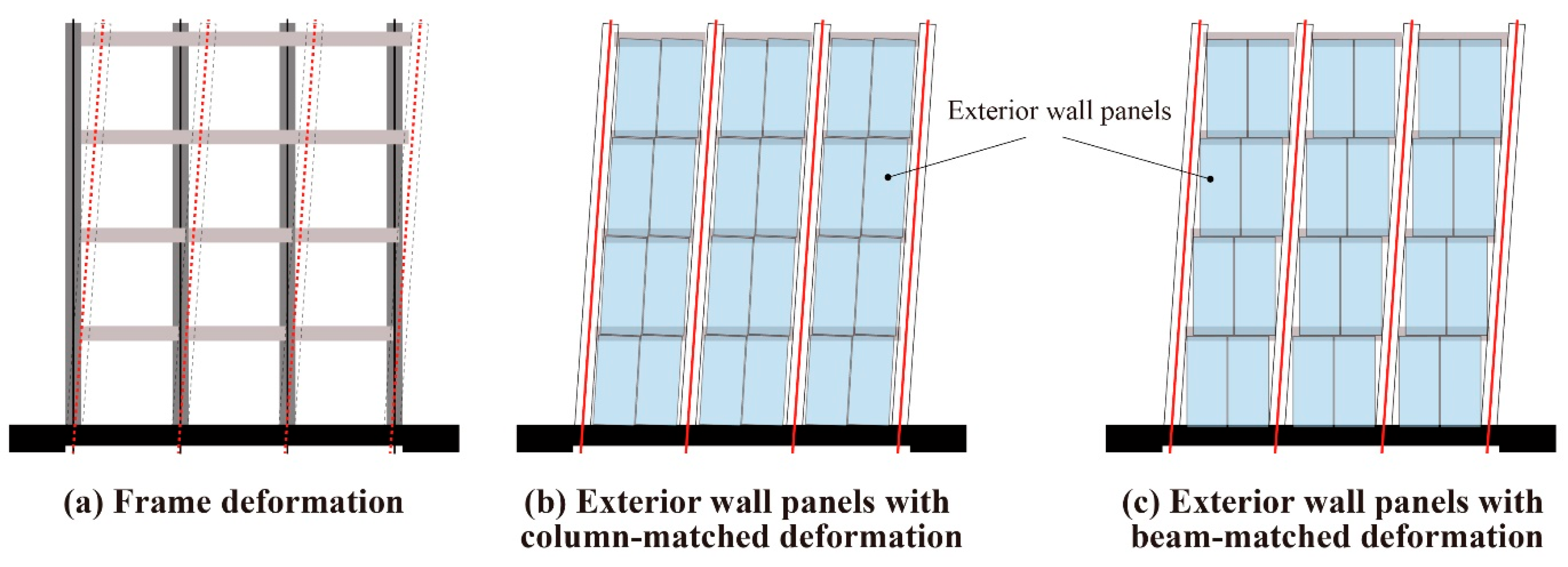
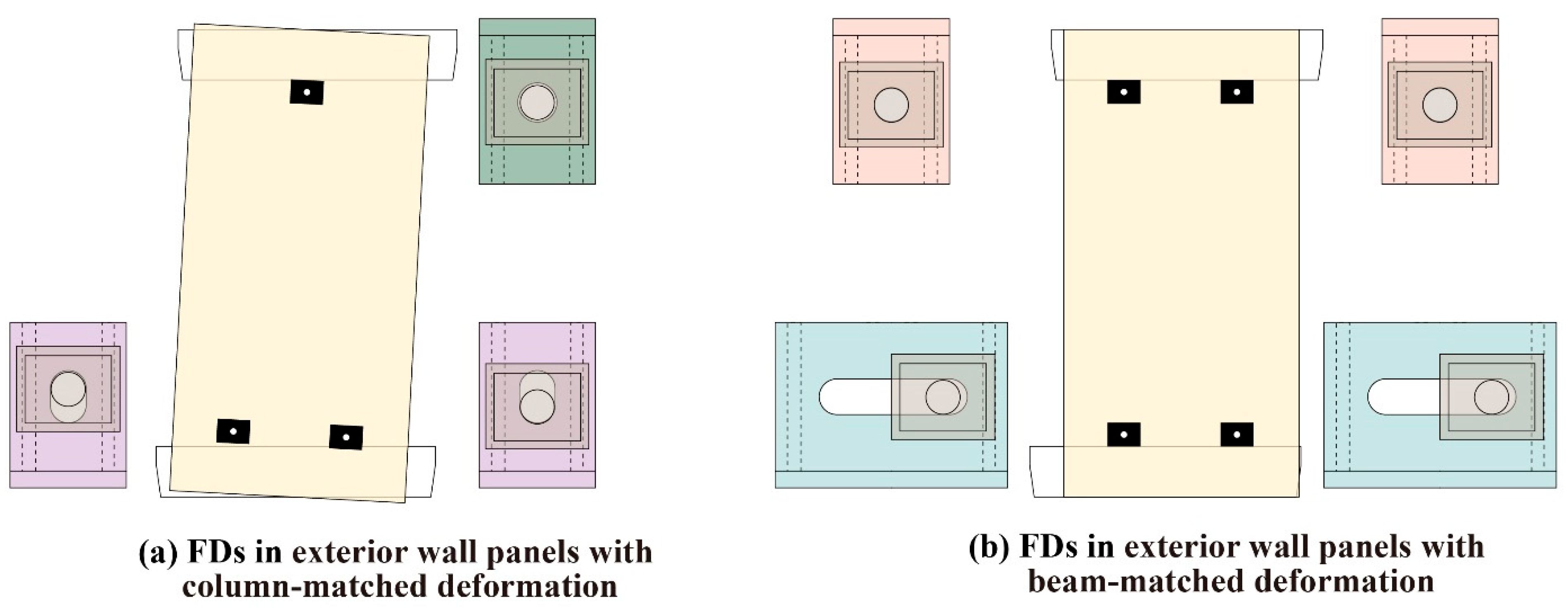
2. Design Concept of Flexible Devices

Building upon traditional frame structures, seismic resilience of self-centering frame structures is achieved by utilizing prestressed steel strands to connect and constrain column components, as shown in Figure 1. In these resilient self-centering frame structures, precast exterior wall panels are further incorporated to meet the functional and maintenance requirements of the building. However, while resilient self-centering frame structures exhibit significant deformability, the exterior wall panels have limited deformation capacity, making them prone to brittle failure. Traditional connection methods are inadequate for achieving the design goal of low damage to the exterior wall panels under large structural deformations.
To ensure cooperative deformation between the exterior wall panels and the self-centering frames, and to minimize damage to the panels, two novel FDs are designed in this paper to facilitate the coordinated deformation of the exterior wall panels with the beams and columns of the frame, as shown in Figure 2. The proposed FDs effectively link the exterior wall panels to the self-centering frame, allowing the relative constraint freedom between components to be released, thereby enhancing the cooperative deformation capability between the exterior wall panels and the self-centering frame. Specifically, the FDs for coordinated deformation between the exterior wall panels and column components are installed on the main self-centering frame through embedded plates pre-installed at appropriate locations in the structural beams. By bolting the exterior wall panels to the main self-centering frame, secure connections are achieved. Under horizontal loads, the FDs ensure that the exterior wall panels move with the beams, with deformation patterns similar to those of the columns, thereby matching the deformation of the exterior wall panels with the columns, as shown in Figure 1b and Figure 2a. Similarly, the FDs for coordinated deformation between the exterior wall panels and beams are bolted to effectively integrate the exterior wall panels with the self-centering frame. Under horizontal loads, these FDs ensure that the wall panels move with the columns, exhibiting a deformation pattern similar to that of the beams, thus coordinating the deformation between the exterior wall panels and beams, as shown in Figure 1c and Figure 2b.

3. Overview of the Experiment

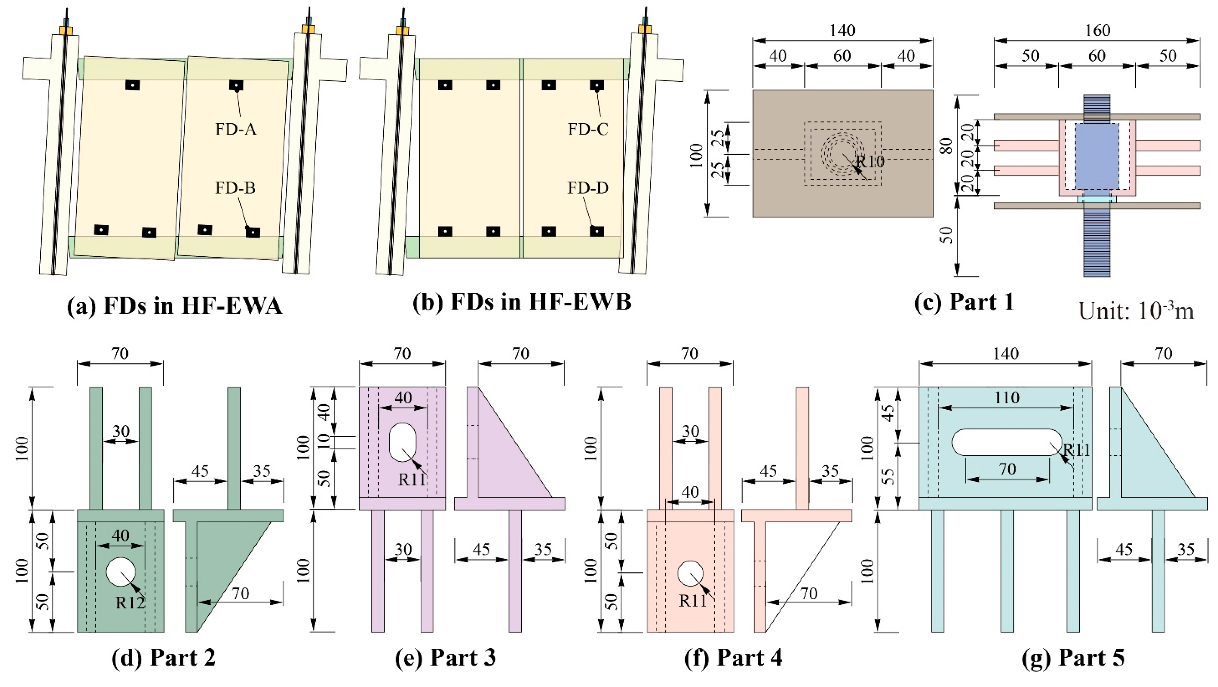
3.1. Specimen Design
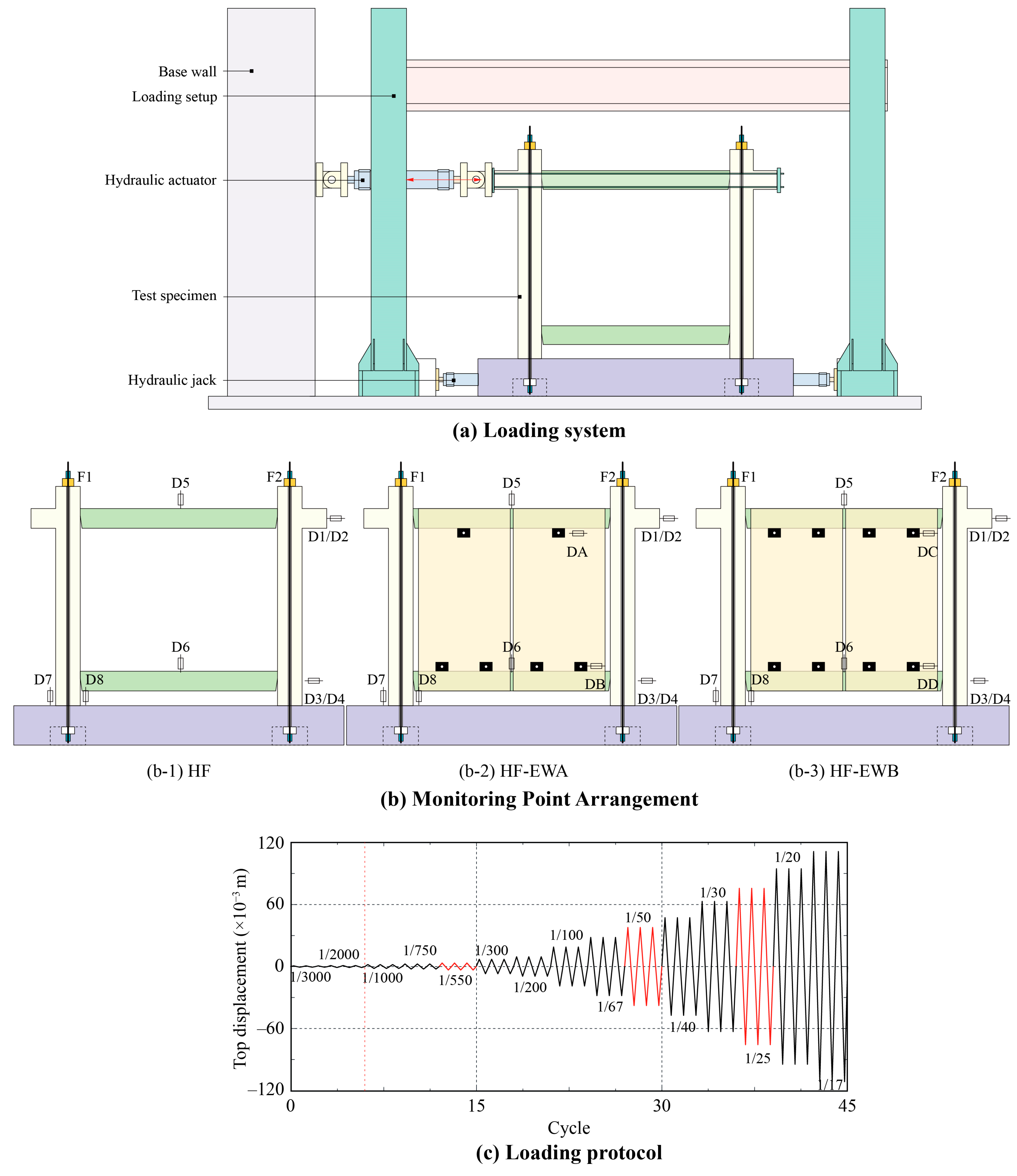
Given the limitations of the experimental conditions and the test site, the specimens were scaled down by a factor of 1:2 from the prototype structure. To relate the results of the scaled experiment to full-scale applications, dimensional analysis based on similarity theory was applied. Since the same materials (concrete and steel) were used in both the model and the prototype, material similarity was preserved. Therefore, when the geometric scale is 1:2, the ratios of the scale model to the real-size structure in terms of displacement, bearing capacity, and stiffness are 1:2, 1:4, and 1:2, respectively. In order to increase the deformation capacity of the main self-centering frame and reduce the damage to structural components, the prototype structure designed for this experiment adopted a resilient self-centering frame with a large deformation capacity as the main structural model (labeled as HF), which serves as the control group for the experiment, as shown in Figure 3a,b. The self-centering frame had a story height of 1.8 m and a span of 2.25 m, designed according to the strong-column and weak-beam principle. The beam cross-sectional dimensions were 150 mm × 200 mm, and the column cross-sectional dimensions were 250 mm × 250 mm. The column was connected to the foundation using unbonded prestressed steel strands with a diameter of 15.2 mm. Post prestress was applied to fix the columns to the foundation.
On the basis of the self-centering frame structure, exterior wall panels were added. The exterior wall panels were made from prefabricated expanded polystyrene (EPS) composite panels with steel-reinforced cement bars, originally sized at 600 mm × 2600 mm and 75 mm thick. To fit the dimensions of the self-centering frame structure, the actual exterior wall panels used in the experiment were 910 mm × 1630 mm. For the HF-EWA specimen, the exterior wall panels were added, and the cooperative deformation mode between the exterior wall panels and the self-centering frame was column-coordinated deformation. Thereinto, the exterior wall panels were formed by joining two cut EPS composite panels, as shown in Figure 3c. For the HF-EWB specimen, the exterior wall panels were added to the frame specimen, and the cooperative deformation mode between the exterior wall panels and the frame was beam-coordinated deformation. Thereinto, the exterior wall panels were also made by joining two cut EPS composite panels, as shown in Figure 3d.
Under the action of horizontal loads, the self-centering frame specimens with additional exterior wall panels are shown in Figure 4a,b. Specifically, FD-A allowed for rotation at the connection node, FD-B facilitated vertical sliding and rotation at the connection joint. FD-C ensured the stability of the joint. The combined effect of the two horizontal FD-Cs ensured that the exterior wall panels could be fixed to the upper beams. FD-D enabled relative horizontal sliding between the exterior wall panels and the lower beams.
To achieve this deformation, FDs with varying degrees of constraint on the degrees of freedom were designed. The specific details of the FDs are shown in Figure 4c–g. In the HF-EWA specimen, FD-A consisted of Part 1 and Part 2, while FD-B consisted of Part 1 and Part 3. Part 1, as the embedded part, was installed in the exterior wall panel, and Part 2 and Part 3 were respectively placed in the upper and lower beams of the self-centering frame. The components were connected by adjusting bolts. Similarly, in the HF-EWB specimen, FD-C was composed of Part 1 and Part 4, and FD-D was composed of Part 1 and Part 5. Part 1 was located in the exterior wall panel, and Part 4 and Part 5 were placed in the upper and lower beams of the self-centering frame, respectively. The connections were also secured by adjusting bolts. The FDs’ design in the test aligns with established performance criteria outlined in standards such as FEMA 461 and similarity theory. To ensure sufficient stiffness of the FDs, all components from Part 1 to Part 5 were fabricated using Q345-grade steel plates. For the mechanical connection, customized high-strength bolts were used, as shown in Figure 4c. These bolts were modified from standard M25 high-strength bolts to fit the specific assembly requirements. As the focus of this study is on the deformation coordination function of the FDs rather than energy dissipation, frictional behavior between contact surfaces was not considered in the design. Accordingly, the contact surfaces were machined until smooth to minimize friction, and the friction coefficient was considered negligible in both the experiments and numerical simulations.
The longitudinal and stirrup reinforcements of the specimens consisted of HRB400-grade deformed steel bars and plain round steel bars, respectively. The measured yield strengths of the steel bars with diameters of 6 mm, 8 mm, 12 mm, and 16 mm were 423.5 MPa, 441.7 MPa, 412.8 MPa, and 401.3 MPa, respectively. The measured tensile strengths were 560.3 MPa, 603.8 MPa, 613.5 MPa, and 597.9 MPa, respectively. Concrete components were made using C30-grade concrete, with the measured compressive strength of 30.7 MPa at 28 days, and the measured compressive strength of 37.3 MPa during the test. The compressive strength of the prefabricated EPS composite panels without reinforcement was 4.2 MPa.

3.2. Loading Scheme

The experiment adopted quasi-static low-cycle loading, with the loading scheme shown in Figure 5. As shown in Figure 5a, the foundations of specimens were anchored to the ground using anchor bolts, and vertical axial loads were applied through the prestress of the prestressed tendons. The initial prestress level was controlled at around 50%, with the initial vertical load of approximately 150 kN applied to the top of each column, resulting in an initial axial load ratio of approximately 0.16.
During the experiment, data from all measurement points were automatically collected by the DH3817 dynamic strain data acquisition instrument, as shown in Figure 5b. The main measured parameters included the following: horizontal load from the actuator measured by force sensors; load on the prestressed tendons measured by pressure sensors; horizontal and vertical displacements at each beam and basement, measured by displacement gauges; and horizontal displacement at key positions of the exterior wall panels and FDs measured by displacement gauges.
The cyclic horizontal loading protocol used in the experiment is detailed in Figure 5c. The loading rate was appropriately adjusted during the test, with displacement-controlled loading applied. Prior to formal loading, a preload was required. The horizontal preload should not exceed 30% of the cracking load. The inter-story drift angles of 1/550, 1/50, and 1/25 correspond to the limit values for the elastic, elasto-plastic, and collapse stages of the self-centering frame structure, respectively. These stages are highlighted in red in the figure and were closely monitored for specimen behavior during these phases.

4. Experimental Results

4.1. Failure Characteristics
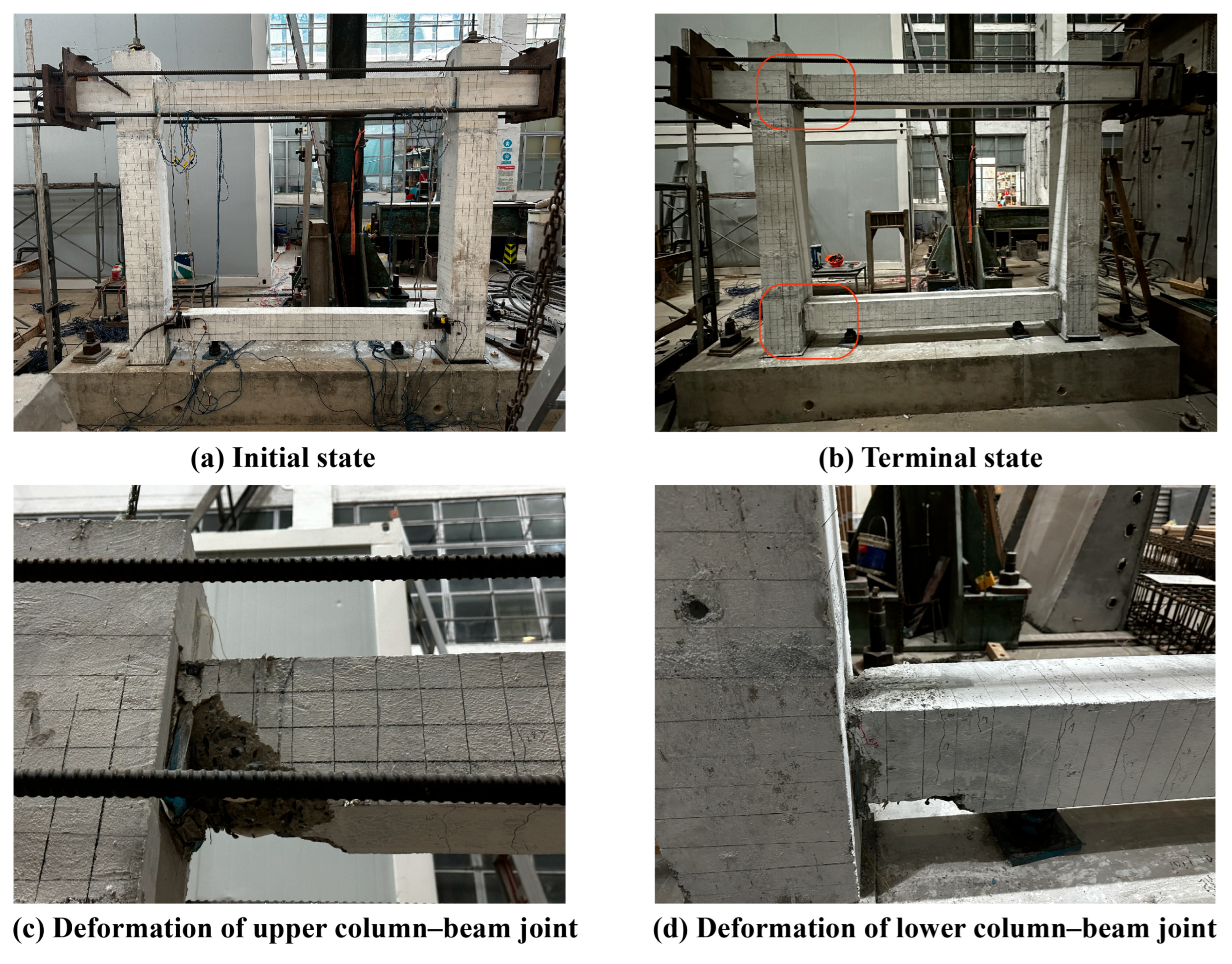
4.1.1. HF Specimen

For the HF specimen, when the inter-story drift angle reached 1/550, the specimen remained intact, with no visible cracks. As the inter-story drift angle increased to 1/300, diagonal cracks began to appear at the beam ends. When the inter-story drift angle reached 1/100, a few vertical cracks emerged at the beam ends, which closed upon the unloading of the structure. With further increases in lateral displacement, these cracks extended and proliferated. When the inter-story drift angle reached 1/50, cracking occurred at the beam–column interface, and energy-dissipating reinforcement yielded. As the inter-story drift angle reached 1/30, concrete crushing appeared at the beam–column interface, accompanied by slight concrete spalling at the base of the columns. Upon loading to an inter-story drift angle of 1/25, concrete spalling was observed at the beam ends at the beam–column interface, while the column elements remained largely intact. A comparison of the experimental loading before and after for the main specimen and beam–column joints is shown in Figure 6.

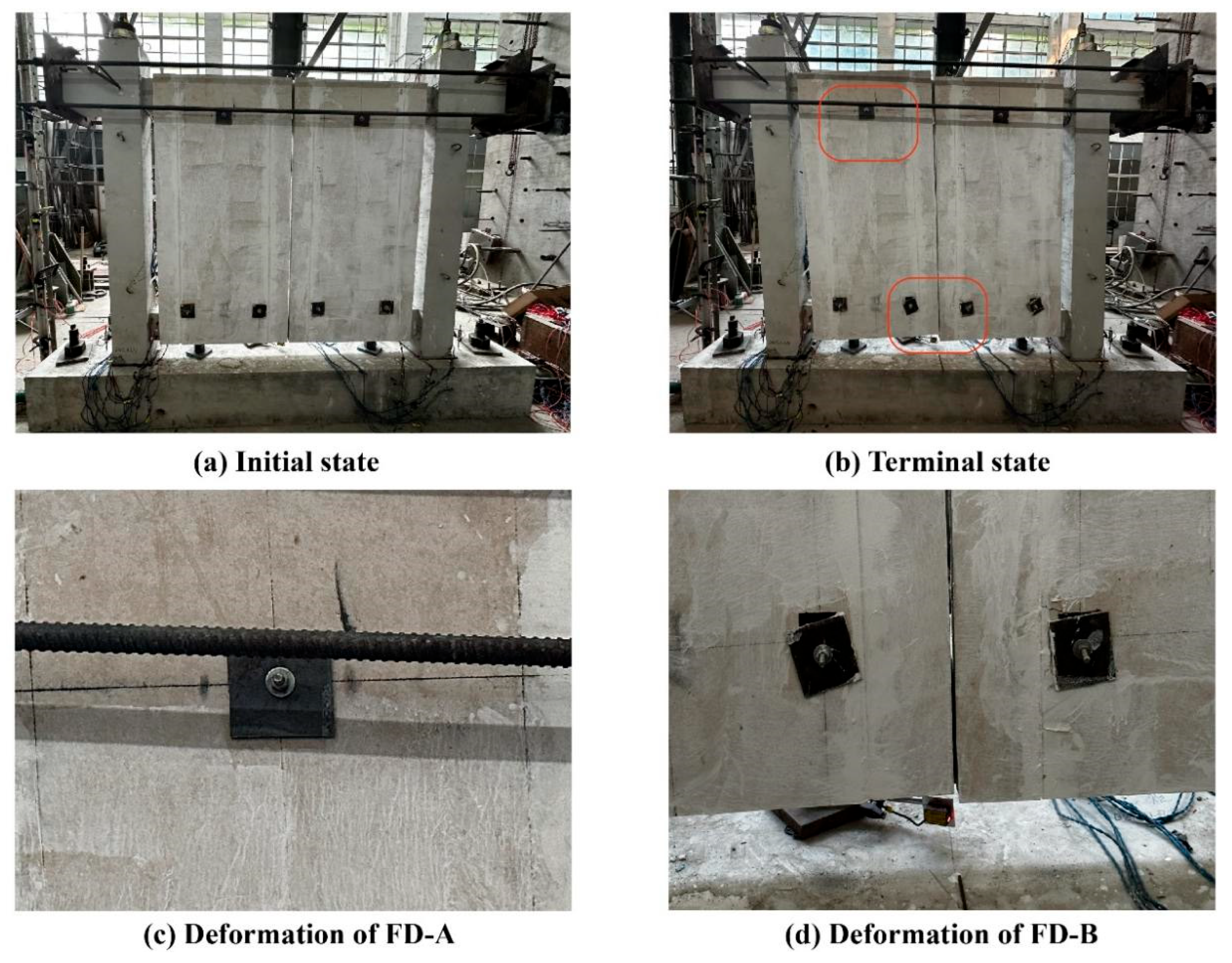
4.1.2. HF-EWA Specimen

For the frame specimen with additional exterior wall panels (HF-EWA), when the inter-story drift angle reached 1/550, the structure remained intact, with no visible cracks. At an inter-story drift angle of 1/300, cracks appeared at the beam ends, which gradually expanded as the loading increased. When the inter-story drift angle reached 1/50, the energy-dissipating reinforcement yielded, and the FDs facilitated cooperative deformation between the exterior wall panels and the frame structure. When the inter-story drift angle reached 1/30, contact occurred between the exterior wall panels and the main frame specimen; however, no significant damage was observed on the exterior wall panels. At an inter-story drift angle of 1/25, out-of-plane deformation occurred on the exterior wall panels, but no significant damage was observed; the panel surfaces remained intact, and no damage was noted at the FDs. As the loading displacement increased, the cover plate of the FD-B rotated, along with the bolts, but this did not affect the performance of the wall. Figure 7 shows the final damage state of the HF-EWA specimen. As seen in Figure 7b, the damage to HF-EWA was similar to that of the HF specimen, indicating that the wall panels connected via FD-A and FD-B did not affect the deformation behavior of the main structure. In addition, as shown in Figure 7c,d, the wall panel’s integrity was well maintained at the connection regions, with no observed damage. Only FD-B exhibited some residual deformation due to rotation.

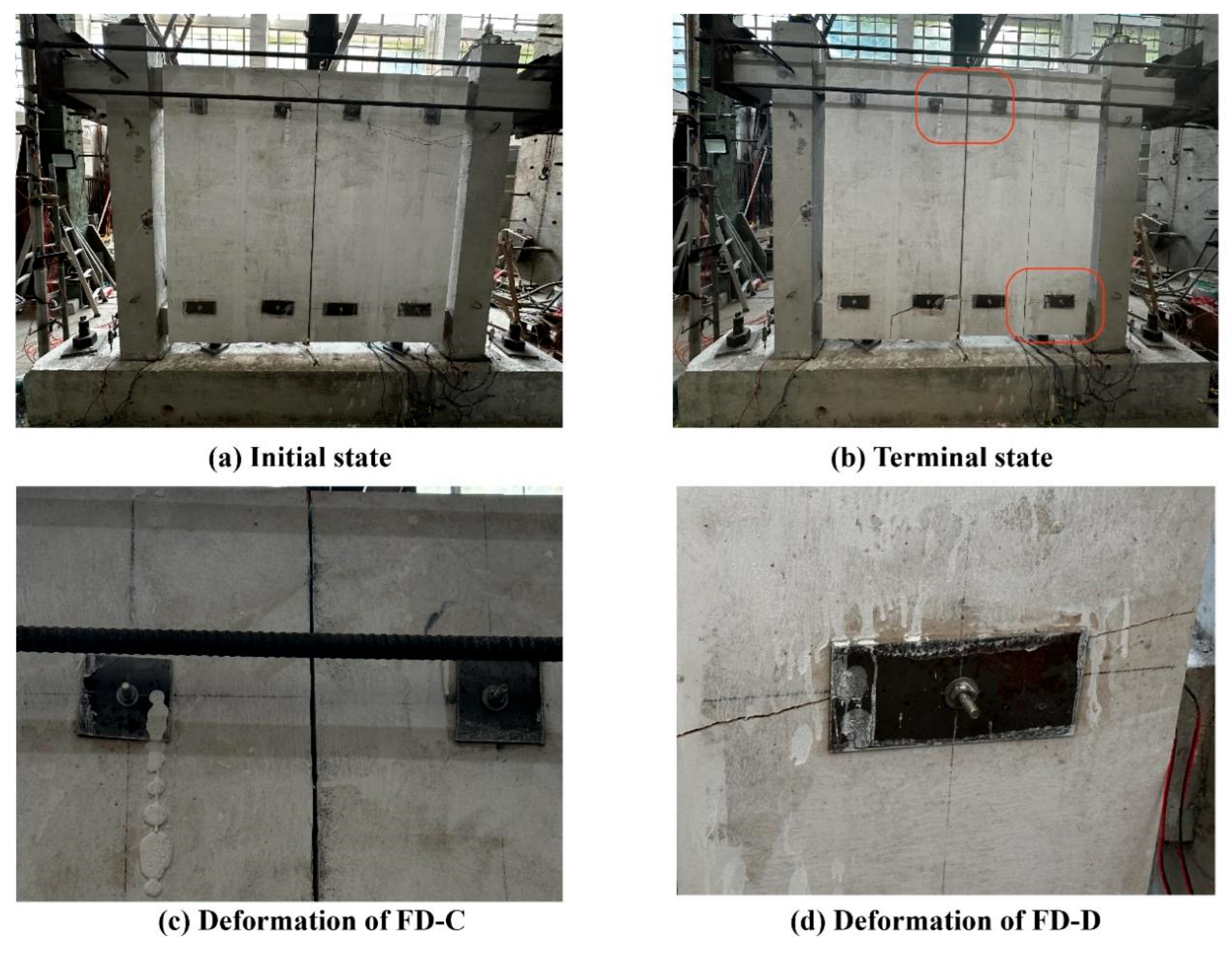
4.1.3. HF-EWB Specimen

For the frame specimen with additional exterior wall panels (HF-EWB), when the inter-story drift angle reached 1/550, the structure remained intact, with no visible cracks. At an inter-story drift angle of 1/200, cracks appeared at the beam ends and gradually expanded as the components were loaded. When the inter-story drift angle reached 1/50, cracks in the main structure continued to propagate, and the energy-dissipating reinforcement yielded. The FD-Ds facilitated cooperative deformation between the frame and the exterior wall panels. When the inter-story drift angle reached 1/30, out-of-plane deformation was observed at the middle of the exterior wall panels, but no significant damage was seen. When the inter-story displacement angle reached 1/25, compression occurred at the wall panel interface, and it was observed that the panels slid along the FD-D, causing the bolts connecting the panels to loosen. However, fracture damage appeared at the interface between the exterior wall panels and the FD-Ds. Figure 8 presents the final damage state of the HF-EWB specimen. As shown in Figure 8b, the damage to HF-EWB was again comparable to that of the HF specimen, indicating that the FD-C and FD-D connections did not compromise the performance of the main structure. Figure 8c,d show that the wall panel connected by FD-C remained intact at the joint area, while the wall panel connected by FD-D exhibited brittle fracture due to insufficient allowable sliding deformation, with a maximum crack width of 4.2 mm.

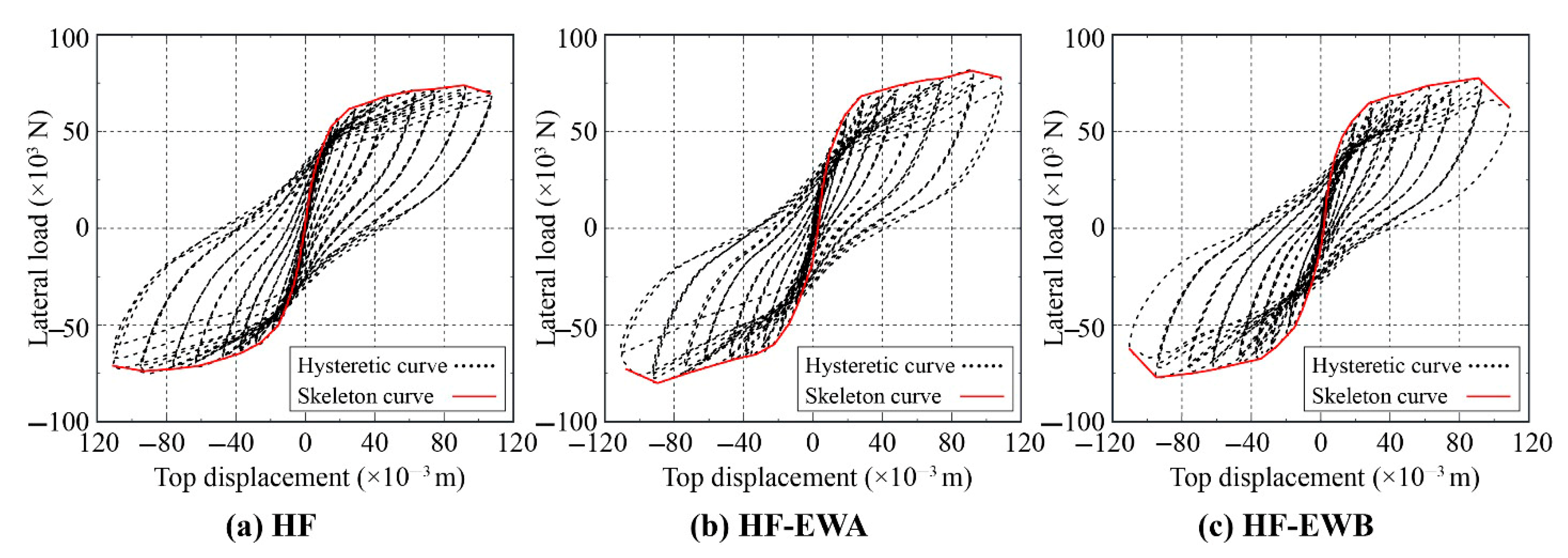
4.2. Hysteretic and Skeleton Curves

The load–displacement (F-Δ) curves at the beam ends for each specimen are shown in Figure 9. As observed, the shape of the hysteretic curve for the self-centering frame specimen with additional exterior wall panels did not exhibit significant changes, indicating that the use of FDs for the exterior wall panels did not have a substantial impact on the seismic performance of the main frame specimens. However, due to the addition of the exterior wall panels, the peak load of the self-centering frame specimen with additional exterior wall panels increased. More importantly, the FDs of the exterior wall panels effectively matched the large deformation capacity of the self-centering frame, ensuring the seismic resilience of non-structural components.
To further analyze the changes in the performance characteristics of the self-centering frame after the addition of exterior wall panels, three characteristic points on the skeleton curve were defined to describe the performance changes in the components: the yield point (Δy, Fy), the peak point (Δm, Fm), and the ultimate point (Δu, Fu). A comparison of the characteristic points on the skeleton curves for specimens is summarized in Table 1. The yield load was determined using the R. Park method. According to the values in the table, the yield load of the specimens with additional exterior wall panels increased by approximately 8.7% and 10.8%, while the peak load increased by approximately 17.1% and 21.6%.

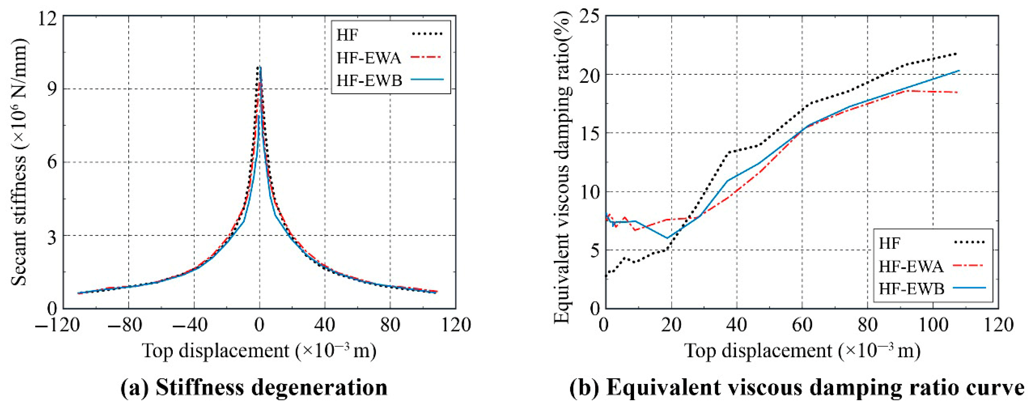
4.3. Stiffness Degradation and Energy Dissipation

To further describe the changes in stiffness and energy dissipation, the secant stiffness and the equivalent viscous damping ratio, as functions of loading displacement, are used herein. Thereinto, the secant stiffness is used to evaluate the stiffness degradation of the specimens, calculated as follows:
K i = j = 1 n F j , max i / j = 1 n Δ j i
where Ki is the secant stiffness, and F j , max   i and Δ j   i are the maximum load and the corresponding peak displacement at the i-th load level for the j-th cycle, respectively.
The equivalent viscous damping ratio can be defined as follows:
ξ eff = 1 4 π E i W s
where Ei is the hysteretic energy dissipated by the structure at the i-th loading step, and Ws is the strain energy of the structure.
The stiffness degradation curves for each specimen are shown in Figure 10a. From the comparison, it can be observed that the HF-EWA and HF-EWB specimens exhibit stiffness degradation characteristics similar to the HF specimen. When the displacement was less than 50 mm, the overall stiffness decreased rapidly due to the continuous cracking of the frame beams and columns as the displacement and number of cycles increased. The stiffness of the HF specimen was slightly higher than that of the HF-EWA and HF-EWB specimens. After the displacement exceeded 50 mm, the stiffness degradation for all three specimens slowed down. The stiffness degradation trend for the HF-EWA and HF-EWB specimens was almost identical, although the initial stiffness of the HF-EWA specimen was greater than that of the HF-EWB specimen.
The variation in the equivalent viscous damping ratio with displacement loading for the self-centering frames with additional exterior wall panels and different FDs is shown in Figure 10b. As seen in the figure, the initial equivalent viscous damping ratio of the HF-EWA and HF-EWB specimens was higher than that of the HF specimen. However, as the displacement increased, the equivalent viscous damping ratios for the HF-EWA and HF-EWB specimens became lower than that of the HF specimen.

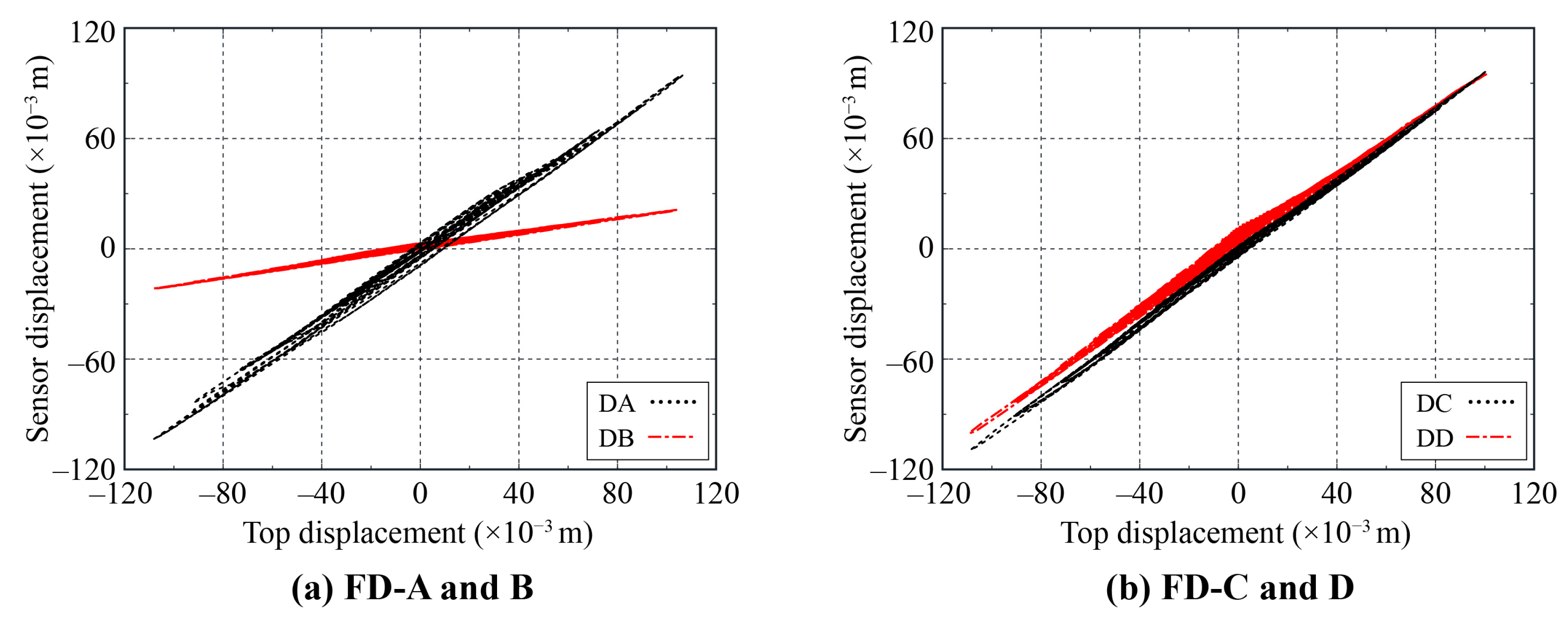
4.4. Displacement of FDs

The displacement of the FDs in the HF-EWA and HF-EWB specimens at their respective locations is shown in Figure 11 for the time during the lateral loading process. As seen in Figure 11a, for the HF-EWA specimen, there was a significant difference in the displacement variations between the FD-A and FD-B. The displacement at FD-A was almost identical to the displacement of the upper beam under horizontal loading, while the displacement at FD-B was nearly the same as that of the lower beam. The displacement at FD-A was 4.56 times that at FD-B. This indicates that the displacement deformation of the FDs in the HF-EWA specimen aligned with the design expectations.
In Figure 11b, for the HF-EWB specimen, the displacement variations at FD-C and FD-D were minimal, with both FD-C and FD-D showing displacement almost identical to the horizontal loading of the upper beam. This indicates that the displacement behavior of the FDs in the HF-EWB specimen was consistent with the expected design. However, due to the later-stage displacement deformation restrictions at FD-D, the bottom of the exterior wall panels was damage in the final state.

5. Finite Element Simulation

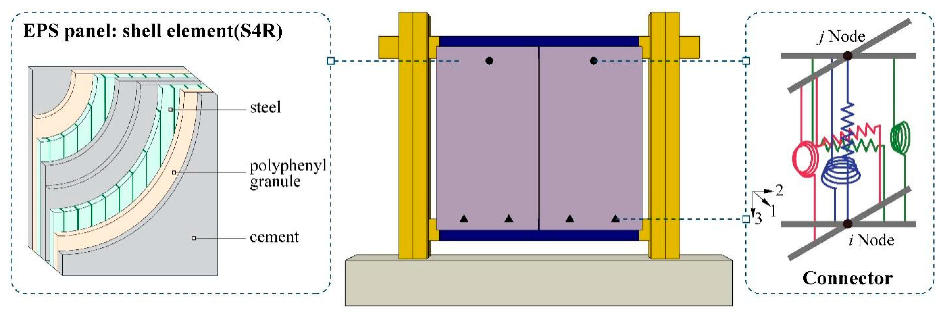
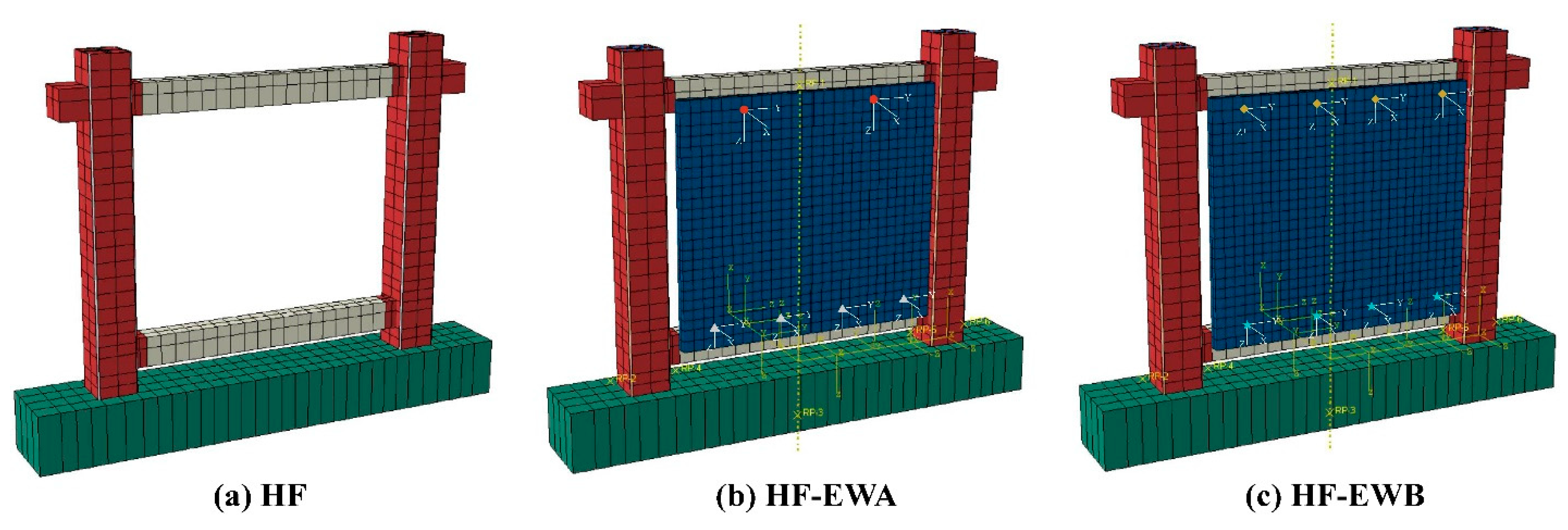
5.1. Numerical Analysis Model

To further investigate the performance variation in the self-centering frames with additional exterior wall panels, numerical analysis models were established using the finite element software ABAQUS based on the experimental scheme, and the correctness of the established model was validated. Considering the consistency of seismic performance research at the structural level, the advantages of various simulation elements were given full play, and the multi-scale modeling method was adopted in the established model. Shell elements (S4R) were used to simulate the main frames, including beams, columns, the loading beam, and solid elements (C3D8R), which were used to simulate the foundation in the finite element model. Contact properties were applied to simulate the interaction between the frame components and the foundation, while truss elements (T3D2) were used to model the reinforcement and prestressed tendons. The interaction between the rebar and concrete was simulated using the rebar layer command, and the prestressed tendons across the frame columns were modeled as an unbonded form, with both ends respectively fixed to the foundation and the top of the frame column via a tie constraint.
For the exterior wall panels in the test specimens, shell elements (S4R) were used. The material properties of the EPS composite panel were simulated by layering the steel, polyurethane, and cement. In the FDs between the self-centering frame and the exterior wall panels, connector elements (CONN3D2) were employed. Considering that the current study did not use energy-dissipation materials, the modeling was primarily based on the boundary constraint conditions of the proposed FDs. The established multi-scale numerical model is shown in Figure 12, which includes the local coordinate system for the connector elements, and the boundary constraint conditions for the FDs are summarized in Table 2. Here, “×” indicates that the degree of freedom is unconstrained and the corresponding stiffness is set to zero, while “√” indicates that the degree of freedom is constrained and the corresponding stiffness is assumed to be rigid (i.e., sufficiently large) in the simulation to ensure no relative deformation.
To ensure the accuracy of the results, the plastic damage constitutive model was used to simulate the concrete, with tensile and compressive damage factors defined to describe the stiffness degradation of concrete under tensile and compressive forces. The steels were modeled using the Menegotto–Pinto model. The material parameters, loading methods, and experimental boundary conditions were consistent with the test setup. During the simulation phase, the numerical problem defined by the model was solved using ABAQUS/Standard. To balance the computational efficiency, different mesh sizes were applied to different components, as shown in Figure 13. Specifically, the mesh for the main frame was relatively coarse and divided according to the distribution of reinforcement, while the mesh for the exterior wall panels was finer due to their complex stress states and significant deformations.

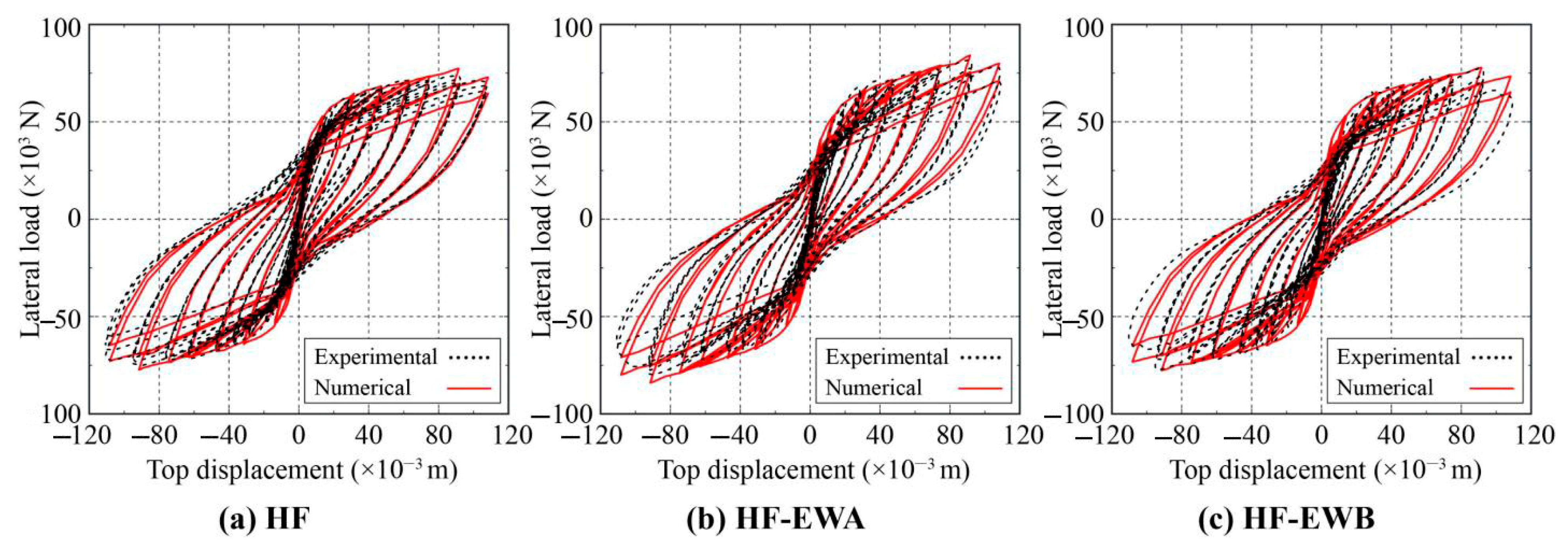
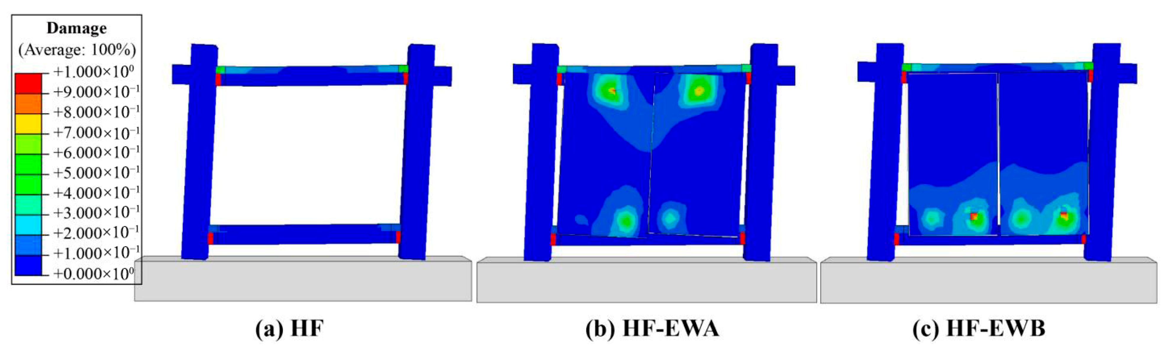
5.2. Correctness Verification

The finite element models and the corresponding numerical analysis results are shown in Figure 14. The simulation results for the HF specimen aligned well with the experimental results, with relative errors of 1.13%, 4.21%, and 2.33% for the yield load, peak load, and ultimate load, respectively. For the frame specimens with additional exterior wall panels, namely the HF-EWA and HF-EWB specimens, the simulation results exhibited similar trends to the experimental curves. For the HF-EWA specimen, the relative errors between the simulated and experimental curves for the yield load, peak load, and ultimate load were 3.97%, 5.88%, and 6.85%, respectively; and for the HF-EWB specimen, the relative errors were 3.85%, 7.85%, and 6.55%, respectively. Therefore, the established numerical model can effectively reflect the impact of the additional exterior wall panels on the overall seismic performance of the structure, and it also clearly demonstrates the role of the proposed FDs between the exterior wall panels and the self-centering frame structure. Therefore, the numerical modeling method presented in this study provides a practical tool for the future optimization of flexible devices and their associated structural systems, as well as for deriving ideal hysteresis curves to support performance-based design [30].
The damage distribution of the specimens, as derived from the model, is shown in Figure 15. From the figure, it can be observed that the damage in the structure was primarily concentrated at the beam–column joints of the main frame. The exterior wall panels with FDs can deform in coordination with the frame structure, but they did not induce secondary damage to the main frame. However, the deformation capacity of the HF-EWA specimen was significantly superior to that of the HF-EWB specimen. Specifically, the HF-EWA specimen demonstrated favorable deformation behavior, with consistent deformation trends observed on both sides of the exterior wall panels, which cooperate well with the deformation of the frame columns. The deformation at the seam between the two wall panels aligned with the experimental results, indicating that the FDs perform as expected. While the HF-EWB specimen also exhibits some deformation capacity, under large deformations, excessive gaps appear at the bottom of the slot between the two wall panels, leading to asynchronous behavior. Although this phenomenon was consistent with both experimental observations and expectations, it is recommended that deformation in such connection devices be limited in practical engineering applications to ensure structural stability and safety.

6. Conclusions

Based on the deformation characteristics of resilient self-centering frame structures under seismic loads, this paper proposed two novel flexible devices (FDs) for connecting exterior wall panels. These FDs achieve the design objective of large deformation and low damage of the exterior wall panels within the self-centering frame structure by coordinating deformation with the frame’s column and beam components, respectively. Through conducting seismic performance experiments and numerical simulations, the feasibility of the proposed FDs was verified. The following conclusions can be drawn:
(1) Cyclic loading tests of self-centering frames with or without exterior wall panels showed that the exterior wall panels connected with the proposed FDs can coordinate deformation with the columns and beams, effectively realizing the intended operational mechanism.
(2) Compared to the raw self-centering frame, the frames with additional exterior wall panels connected by the proposed FDs demonstrated enhanced seismic performance and reduced damage to both structural components and exterior panels, with peak load capacities increased by approximately 17.1% and 21.6%, respectively.
(3) A comparative analysis of the two proposed FDs revealed that frames utilizing FDs with a column-matched deformation mechanism exhibited superior deformation coordination and damage control performance compared to those using FDs with a beam-matched deformation mechanism.
(4) The established numerical models based on the finite element software ABAQUS can effectively simulate the seismic responses and failure characteristics of self-centering frame structures with exterior wall panels connected by the proposed FDs, providing a practical auxiliary tool for further parametric analysis research.
The development and successful validation of these innovative FDs contribute to the advancement of current resilient structural system design. However, this study has certain limitations, such as the lack of consideration for energy dissipation and the absence of dynamic loading tests, both of which are critical for enhancing and evaluating structural performance under realistic seismic conditions. Therefore, future research is recommended to improve the proposed FDs from the perspective of enhancing energy dissipation capacity and to incorporate dynamic and multi-directional loading scenarios in order to further investigate the practicality and effectiveness of the proposed FDs in real-world engineering applications.

Author Contributions

Conceptualization, C.Z.; software, W.G.; validation, X.L.; formal analysis, W.G.; investigation, C.Z.; writing—original draft preparation, C.Z.; writing—review and editing, X.L. and W.G.; funding acquisition, C.Z., X.L. and W.G. All authors have read and agreed to the published version of the manuscript.

Funding

This research was funded by National Natural Science Foundation of China (Grant No. 52208490 and Grant No. 52208320) and Shanghai Pujiang Program (Grant No. 24PJD136).

Data Availability Statement

The data that has been used is confidential.

Acknowledgments

This work was partially supported by National Natural Science Foundation of China (Grant No. 52208490 and Grant No. 52208320) and the Shanghai Pujiang Program (Grant No. 24PJD136). The authors would like to acknowledge these financial supporters. The first author would like to thank her dearest baby, Gao Shaotang, for his support and to commemorate his healthy birth on 30 April 2025.

Conflicts of Interest

Author Xiao Lai was employed by China Nuclear E&C Group Innovation Technology Co. Ltd. The remaining authors declare that the research was conducted in the absence of any commercial or financial relationships that could be construed as a potential conflict of interest.

References

  1. Dhakal, R.P.; Pourali, A.; Tasligedik, A.S.; Yeow, T.; Baird, A.; MacRae, G.; Pampanin, S.; Palermo, A. Seismic performance of non-structural components and contents in buildings: An overview of NZ research. Earthq. Eng. Eng. Vib. 2016, 15, 1–17. [Google Scholar] [CrossRef]
  2. Nader, K.A.; Zargaran, M.; Jahromi, K.K.; Bayat, M.R.; Jahanmohammadi, A. Seismic evaluation of cladded exterior walls considering the effects of facade installation details and out-of-plane behavior of walls. Structures 2020, 24, 317–334. [Google Scholar] [CrossRef]
  3. Braga, F.; Manfredi, V.; Masi, A.; Salvatori, A.; Vona, M. Performance of non-structural elements in RC buildings during the L’Aquila, 2009 earthquake. Bull. Earthq. Eng. 2011, 9, 307–324. [Google Scholar] [CrossRef]
  4. Furtado, A.; Rodrigues, H.; Arêde, A.; Varum, H. A review of the performance of infilled RC structures in recent earthquakes. Appl. Sci. 2021, 11, 5889. [Google Scholar] [CrossRef]
  5. Kam, W.Y.; Pampanin, S. The seismic performance of RC buildings in the 22 February 2011 Christchurch earthquake. Struct. Concr. 2011, 12, 223–233. [Google Scholar] [CrossRef]
  6. Ercolino, M.; Magliulo, G.; Manfredi, G. Failure of a precast RC building due to Emilia-Romagna earthquakes. Eng. Struct. 2016, 118, 262–273. [Google Scholar] [CrossRef]
  7. Senel, S.M.; Haydar, K.A.; Mehmet, P.; Demir, A. Assessment of Damages in Precast Industrial Buildings in the Aftermath of Pazarcık and Elbistan Earthquakes. J. Earthq. Eng. 2024, 1–30. [Google Scholar] [CrossRef]
  8. Dal Lago, B.; Lamperti Tornaghi, M. Sliding channel cladding connections for precast structures subjected to earthquake action. Bull. Earthq. Eng. 2018, 16, 5621–5646. [Google Scholar] [CrossRef]
  9. Palsson, H.; Goodno, B.J.; Craig, J.I.; Will, K.M. Cladding influence on dynamics response of tall buildings. Earthq. Eng. Struct. Dyn. 1984, 12, 215–228. [Google Scholar] [CrossRef]
  10. Biondini, F.; Dal Lago, B.; Toniolo, G. Role of wall panel connections on the seismic performance of precast structures. Bull. Earthq. Eng. 2013, 11, 1061–1081. [Google Scholar] [CrossRef]
  11. Jiang, Q.; Wang, H.; Feng, Y.; Chong, X.; Huang, J.; Liu, Y. Enhancing the seismic performance of precast RC frames with cladding panels through setting U-shaped dampers and rocking walls. Shock Vib. 2020, 2020, 4182094. [Google Scholar] [CrossRef]
  12. Sellers, V.A. Experimental Testing of a Rotational Friction Connection for Use with Precast Concrete Cladding Panels in Metal Building Systems. Master’s Thesis, Auburn University, Auburn, AL, USA, 2017. [Google Scholar]
  13. Karadogan, F.; Yüksel, E.; Khajehdehi, A.; Ozkaynak, H.; Gullu, A.; Senol, E. Cyclic behavior of reinforced concrete cladding panels connected with energy dissipative steel cushions. Eng. Struct. 2019, 189, 423–439. [Google Scholar] [CrossRef]
  14. Brunesi, E.; Nascimbene, R.; Peloso, S. Evaluation of the seismic response of precast wall connections: Experimental observations and numerical modeling. J. Earthq. Eng. 2020, 24, 1057–1082. [Google Scholar] [CrossRef]
  15. Hou, H.; Yan, X.; Qu, B.; Du, Z.; Lu, Y. Cyclic tests of steel tee energy absorbers for precast exterior wall panels in steel building frames. Eng. Struct. 2021, 242, 112561. [Google Scholar] [CrossRef]
  16. Rahmanishamsi, E.; Soroushian, S.; Maragakis, E.M.; Shirazi, R. Analytical model for seismic assessment of nonstructural partition walls with returns. In Proceedings of the 16th World Conference on Earthquake Engineering, Santiago, Chile, 9–13 January 2017. [Google Scholar]
  17. Xie, L.; Sha, H.; Chong, X.; Jia, J. Seismic performance comparison between reinforced concrete frame structures with and without energy dissipating cladding panel system: Shaking table test and numerical simulation. J. Build. Eng. 2022, 62, 105414. [Google Scholar] [CrossRef]
  18. Su, R.K.L.; Chandler, A.M.; Sheikh, M.N.; Lam, N.T.K. Influence of non-structural components on lateral stiffness of tall buildings. Struct. Des. Tall Spec. Build. 2005, 14, 143–164. [Google Scholar] [CrossRef]
  19. Li, B.; Hutchinson, G.L.; Duffield, C.F. The influence of non-structural components on tall building stiffness. Struct. Des. Tall Spec. Build. 2011, 20, 853–870. [Google Scholar] [CrossRef]
  20. Pinelli, J.-P.; Craig James, I.; Goodno Barry, J. Energy-based seismic design of ductile cladding systems. J. Struct. Eng. 1995, 121, 567–578. [Google Scholar] [CrossRef]
  21. Dal Lago, B.; Biondini, F.; Toniolo, G. Seismic performance of precast concrete structures with energy dissipating cladding panel connection systems. Struct. Concr. 2018, 19, 1908–1926. [Google Scholar] [CrossRef]
  22. Toniolo, G.; Dal Lago, B. Conceptual design and full-scale experimentation of cladding panel connection systems of precast buildings. Earthq. Eng. Struct. Dyn. 2017, 46, 2565–2586. [Google Scholar] [CrossRef]
  23. Baird, A. Seismic Performance of Precast Concrete Cladding Systems. Ph.D. Thesis, University of Canterbury, Christchurch, New Zealand, 2014. [Google Scholar]
  24. Dal Lago, B.; Biondini, F.; Toniolo, G. Friction-based dissipative devices for precast concrete panels. Eng. Struct. 2017, 147, 356–371. [Google Scholar] [CrossRef]
  25. Dal Lago, B.; Biondini, F.; Toniolo, G. Experimental investigation on steel W-shaped folded plate dissipative connectors for horizontal precast concrete cladding panels. J. Earthq. Eng. 2018, 22, 778–800. [Google Scholar] [CrossRef]
  26. Biondini, F.; Palermo, A.; Toniolo, G. Seismic performance of concrete structures exposed to corrosion: Case studies of low-rise precast buildings. Struct. Infrastruct. Eng. 2011, 7, 109–119. [Google Scholar] [CrossRef]
  27. Yarmohamadi, P.; Javadi, P.; Aziminejad, A. Improvement of seismic performance of self-centering mid-rise RC frames by adding semi-rigid rocking columns. Bull. Earthq. Eng. 2023, 21, 5991–6028. [Google Scholar] [CrossRef]
  28. Li, S.; Liu, H.; Wang, H.; Zar, A.; Zhai, C. Experimental Research on the Seismic Performance of Self-Centering Precast Concrete Frames With Infill Walls. Earthq. Eng. Struct. Dyn. 2025, 54, 2303–2324. [Google Scholar] [CrossRef]
  29. Yang, Y.; Yang, P.; Zhu, X.; Cui, J.; Liu, X. Seismic performance of steel frames with different configurations of self-centering joints. Structures 2025, 74, 108480. [Google Scholar] [CrossRef]
  30. Kazemi, F.; Asgarkhani, N.; Lasowicz, N.; Jankowski, R. Development and experimental validation of a novel double-stage yield steel slit damper-buckling restrained brace. Eng. Struct. 2024, 315, 118427. [Google Scholar] [CrossRef]
Figure 1. Diagram of exterior wall deformation.
Buildings 15 02478 g001
Figure 2. Illustration of the designed FDs.
Buildings 15 02478 g002
Figure 3. Schematic diagram of the experimental specimens.
Buildings 15 02478 g003
Figure 4. Composition and dimensions of the FDs in the specimens.
Buildings 15 02478 g004
Figure 5. Experimental scheme.
Buildings 15 02478 g005
Figure 6. Failure characteristics of the HF specimen.
Buildings 15 02478 g006
Figure 7. Failure characteristics of the HF-EWA specimen.
Buildings 15 02478 g007
Figure 8. Failure characteristics of the HF-EWB specimen.
Buildings 15 02478 g008
Figure 9. Load–displacement curves.
Buildings 15 02478 g009
Figure 10. Stiffness degradation and equivalent viscous damping ratio curves.
Buildings 15 02478 g010
Figure 11. Relationship between displacement at FDs and specimens.
Buildings 15 02478 g011
Figure 12. Numerical modeling principle for the exterior wall panel and FDs.
Buildings 15 02478 g012
Figure 13. Finite element models of the specimens.
Buildings 15 02478 g013
Figure 14. Comparison of the load–displacement curves.
Buildings 15 02478 g014
Figure 15. Damage-distribution contour plot.
Buildings 15 02478 g015
Table 1. Characteristic points for the specimens with or without exterior walls.
Fy/kNΔy/mmFm/kNΔm/mmFu/kNΔu/mm
HFForward45.8210.9271.4892.2470.08107.55
Reverse−46.14−13.33−70.96−94.95−70.81−110.81
HF-EWAForward51.9615.6379.9192.5773.10109.16
Reverse−56.16−16.87−85.58−91.20−77.71−106.55
HF-EWBForward54.0517.9682.9491.5774.94107.98
Reverse−57.85−20.21−88.63−90.22−80.46−105.40
Table 2. Degree-of-freedom constraints in the connector elements of FDs.
Direction1(ux)2(uy)3(uz)4(urx)5(ury)6(urz)
FD-A×××××
FD-B××××
FD-C××××××
FD-D×××
Disclaimer/Publisher’s Note: The statements, opinions and data contained in all publications are solely those of the individual author(s) and contributor(s) and not of MDPI and/or the editor(s). MDPI and/or the editor(s) disclaim responsibility for any injury to people or property resulting from any ideas, methods, instructions or products referred to in the content.

