Article

Seismic Response Characteristics of High-Speed Railway Hub Station Considering Pile-Soil Interactions

Department of Underground Engineering, Nanjing Tech University, Nanjing 211816, China
*
Author to whom correspondence should be addressed.
Buildings 2025, 15(14), 2466; https://doi.org/10.3390/buildings15142466
Submission received: 26 May 2025 / Revised: 30 June 2025 / Accepted: 11 July 2025 / Published: 14 July 2025

Abstract

As a key transportation infrastructure, it is of great significance to ensure the seismic safety of the high-speed railway hub station. Taking Changde high-speed railway hub station as background, a comprehensive 3D numerical model of the high-speed railway station structure is proposed to consider the engineering geological characteristics of the site, soil nonlinearity, and pile-soil interactions. The results show that the hub station structural system, considering pile-soil interaction, presents the ‘soft-upper-rigid-down’ characteristics as a whole, and the natural vibration is lower than that of the station structure with a rigid foundation assumption. Under the action of three strong seismic motions, the nonlinear site seismic effect is significant, the surface acceleration is significantly enlarged, and decreases with the buried depth. The interaction between pile and soil is related to the nonlinear seismic effect of the site, which deforms together to resist the foundation deformation caused by the strong earthquake motions, and the depth range affected by the interaction between the two increases with the increase of the intensity of earthquake motion. Among the three kinds of input earthquake motions, the predominant frequency of the Kobe earthquake is the closest to the natural vibration of the station structure system, followed by the El Centro earthquake. Moreover, the structures above the foundation of the high-speed railway hub station structural system are more sensitive to the spectral characteristics of Taft waves and El Centro waves compared to the site soil. This is also the main innovation point of this study. The existence of the roof leads to the gradual amplification of the seismic response of the station frame structure with height, and the seismic response amplification at the connection between the roof and the frame structure is the largest. The maximum story drift angle at the top floor of the station structure is also greater than that at the bottom floor.

1. Introduction

With the high-quality development of the Chinese economy in recent years, more and more high-speed railway hub stations have been put into operation. The dynamic characteristics and dynamic response of these station structures are complex [1,2], and they interact with the lower pile-soil structure. It is of great significance to study the seismic response characteristics of the high-speed railway hub station structure, considering the pile-soil interaction to ensure its seismic safety. In the previous research on the structure of high-speed railway hub stations, the substructure is usually simplified first, and then the dynamic response characteristics of the overall structure or local structure under the action of earthquake motion are explored [3,4,5,6,7,8]. There are relatively few studies on the seismic response of the interaction between the station frame structure and the upper roof structure under the action of earthquake motion. At the same time, there are few studies on the seismic response characteristics of the high-speed railway hub station structure system considering pile-soil interaction.
At present, the upper roof of many high-speed railway hub stations is mostly a steel grid structure or truss structure, and the substructure is mostly a concrete frame structure, or is combined with other seismic isolation and energy dissipation measures [9,10]. In previous studies, based on numerical simulation software, Yu [11] conducted shaking table tests and numerical simulations on a three-story concrete structure-pile-soil system. The results indicated that the failure mode of the pile shaft was bending tensile failure. For the pile-soil system without an upper structure, the variation of the input earthquake motion amplitude had a negligible effect on the acceleration amplification coefficient of the pile foundation and could be disregarded. Liu et al. [12] analyzed the horizontal dynamic response law of the pile-soil-structure system by combining the shaking table test and numerical simulation analysis. The results show that with the increase of the mass of the superstructure, the acceleration response between the soil and the pile foundation increases, and the bending moment and shear force of the pile body also increase. Moreover, the change of the mass of the superstructure has the greatest influence on the dynamic interaction of the pile-soil-structure system. The bending moment and shear force of the pile body are the greatest at the connection between the pile and the pier cap, and they decrease with the increase of depth. Xu [13] conducted a study on the seismic performance of frame structures considering pile-soil-structure interaction. The results show that after considering pile-soil-structure interaction, the seismic response at the vertex, the story drift and the peak value of the base shear force of the superstructure under the action of seismic waves of different spectra in the time domain all increase, and the influence of pile length on the seismic performance of the structure is greater than that of pile diameter. Wang et al. [14] established a two-dimensional model to analyze the stress characteristics of the Dakai station structure under earthquake motion and obtained some seismic response characteristics of the Dakai station. Muhammad et al. [15] studied the composite steel components as seismic materials. The feasibility study shows that the steel sections of building structures can serve as resonant barriers to mitigate seismic waves and protect important civil infrastructure from earthquake hazards. Zhuang et al. [16,17,18,19] established two-dimensional and three-dimensional models based on finite element numerical simulation software, systematically studied the earthquake motion response characteristics of subway station structures, and mainly analyzed the seismic response mechanism of subway station structures. Chen et al. [20,21,22,23] established a refined model of the underground structure through the finite element numerical simulation software and systematically studied the influence of site conditions and input earthquake motion characteristics on the nonlinear seismic response characteristics and spatial effect characteristics of the subway station structure in combination with the indoor shaking table test. Wang et al. [24] conducted a study on the influence range of the end effect of the subway station structure and revealed the spatial effect mechanism generated by the co-movement of the soil-underground structure in detail. Yang et al. [25] analyzed the seismic performance of reinforced concrete frame subway station structures based on numerical simulation. The results show that the installation of lead rubber bearings on the top of the central column of the station structure can effectively reduce the seismic damage to the central column and the inner plate, and the lateral deformation of the central column. Zhao et al. [26] conducted a three-dimensional weak coupling effective stress analysis of soil-underground structure interaction, and the proposed effective stress method can effectively reflect the dynamic action characteristics between soil and underground structure during the test. Gholizadeh et al. [27] investigated the seismic performance of steel torque-resistant frame structures considering the SSI effect. The results show that when SSI is taken into account during the optimization process of frame structures, the structural weight increases, and the seismic safety of the structure slightly decreases at different confidence levels. Zhu et al. [28] explored the seismic response characteristics of the nuclear island structure, considering the pile-raft-soil interaction. Their study found that the peak acceleration amplification factor of the nuclear island structure increases with the increase of the structural height. The nonlinear order effect of the site soil significantly increases the peak acceleration and relative displacement of the nuclear island structure and reduces the stiffness of the pile-raft-soil-nuclear island structure system. From the above research, it can be seen that using finite element software to conduct a detailed modeling of the high-speed railway hub station structural system, considering pile-soil interactions, and thoroughly exploring its mechanical properties and response characteristics under the action of seismic forces is of great significance. Therefore, this paper conducts a study on the seismic response characteristics of the Changde high-speed railway hub station structure, considering pile-soil interactions under the action of different seismic forces using the ABAQUS finite element numerical simulation platform. The focus is on exploring the dynamic response characteristics of the overall structure and local components of the upper part of the hub station, as well as the lower group piles and site soil. The influence of earthquake motion and pile-soil interaction on the seismic response of the high-speed railway hub station structure system was obtained. This study can provide some reference value for the analysis of seismic response characteristics of high-speed railway hub station structure systems in the future.

2. Establishment of Finite Element Model of Station Structure System

2.1. Engineering Backgrounds and Model Establishment

Changde high-speed railway hub station adopts the structural form of ‘building and bridge integration’ [29,30]. The upper roof of the station is composed of longitudinal and transverse steel pipe trusses, including transverse and longitudinal main trusses and secondary trusses. The length, width, and height of the roof are 87 m, 45.1 m, and 7.5 m, respectively. The left and right sides and the front side are tilted at 35 degrees and 20 degrees, respectively. The diameter range of the roof bar is 5–10 cm, and some joints of the roof and 28 columns in the lower part are fixed. The lower three-layer structure adopts a reinforced concrete frame structure; the first layer of the station is 7.77 m high, and the upper floor is 156 m long, 68.15 m wide, and 0.15 m thick. The height of the second floor is 8.25 m, and the size of the upper floor is 132 m long, 62.15 m wide, and 0.15 m thick. The minimum height of the columns on the third floor is 9.3 m. The size of the model site is 230 m long, 134.15 m wide, and 55.6 m thick. The site soil consists of backfill soil, clay, silt, and sand. A total of 352 piles are embedded in the soil to simulate the soil-pile interactions [31,32]. The diameter of these piles is 0.6 m, with a length of 14.4 m, and the top of the piles is embedded in the pile cap by 0.15 m. The top of the pile and the lower part of the concrete cap are fixed. In the process of seismic earthquake motion, the pile-soil interaction is reflected by the joint load carrying and interaction between the piles embedded in the soil and the site soil. The lower surface of the pile cap is fixed to the upper surface of the site soil.

2.2. The Mesh Layout and the Input Earthquake Motion of the Model

The three-dimensional two-node T3D2 truss element is used to simulate the roof structure. When meshing, it is divided into 3944 elements, and the three-dimensional two-node B31 beam element is used to simulate the beam, column, and pile components. The beams of the first- and second-floor frame structures are divided into 780 and 1504 units, respectively, and the columns of the three-layer structure are divided into 284,372 and 768 units, respectively. The two slabs are divided into 4992 and 6588 elements by shell elements, respectively. The 8-node linear reduction integral element C3D8R is used to simulate the bottom site soil and pile cap. Due to the spatial nonuniformity of sedimentary soil, the site soil is divided into non-uniform grids. The five-layer site soil is divided into 623,092 block units. In addition to the site soil and steel roof, all structural members are made of C40 concrete, and the material parameters of concrete and steel are shown in Table 1.

2.3. Artificial Boundary Conditions

The simulation accuracy of the seismic response of the high-speed railway station structure system, considering pile-soil interaction, is highly correlated with the input method of earthquake motion. To reduce the computational scale, an improved viscoelastic artificial boundary condition is set at the four lateral boundaries and the bottom of the computational domain to allow the scattered wave to propagate through the artificial boundary to the infinite domain without reflection [33]. The effectiveness of the artificial boundary condition has been verified by 2D and 3D nonlinear earthquake response analysis [34,35].
The adopted boundary can absorb the scattered wave energy on the boundary and simulate the recovery capacity of the semi-infinite foundation. The difficulty of viscous-spring artificial boundaries lies in that after establishing the model, the stiffness of the spring and the damping coefficient of the damper at the nodes need to be determined based on the soil density, shear modulus, shear wave velocity, longitudinal wave velocity, correction coefficient and grid size, and applied to the boundary nodes one by one. The specific calculation formula is as follows:
K B T = α T G R , C B T = ρ C S K B N = α N G R , C B N = ρ C P
where KBT, KBN represent the stiffness coefficients of the tangential and normal springs; CBT, CBN are the damping coefficients of the tangential and normal dampers, respectively; αT, αN are the correction coefficients of the viscoelastic boundary, which have different values in two-dimensional and three-dimensional models. R is the distance from the wave source to the artificial boundary; ρ is the density of soil mass; G is the shear modulus; CS and CP are, respectively, the shear wave velocity and longitudinal wave velocity of the soil mass.

2.4. Verification of the Site Soil Model

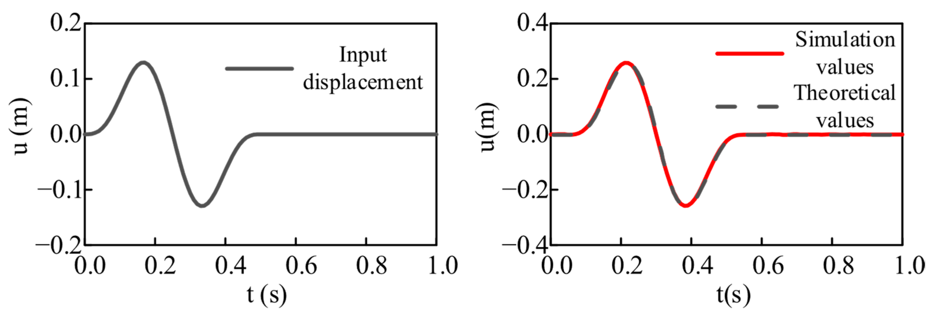
In order to verify the viscoelastic artificial boundary and equivalent nodal force, soil with a length, width and height of 20 m × 20 m × 10 m, a density of 2000 kg/m3, an elastic modulus of 200 MPa, a Poisson’s ratio of 0.25, a shear wave velocity of 200 m/s, and a longitudinal wave velocity of 346.41 m/s was selected. The horizontal displacement function at the bottom of the model is as follows:
u ( t ) = 0.1 sin ( 4 π t ) 0.05 sin ( 8 π t ) 0 t 0.5 s 0 t > 0.5 s
Figure 1 shows the effect of applying equivalent nodal forces and viscous-spring artificial boundaries at the model boundaries. Since the ground spring cannot be used in the displayed dynamic analysis of ABAQUS, we need to add the established mass block in the inp file, bind it to the boundary node, and apply the spring stiffness coefficient and the damper damping coefficient.
According to the wave theory, the surface displacement in the elastic half-space model theory should be twice the input displacement. The results are shown in Figure 2. Among them, the simulated values are in good agreement with the theoretical values, indicating that the application of viscous-spring boundaries and equivalent nodal forces is reasonable and effective, and the simulation of seismic wave propagation can be carried out in a finite space.
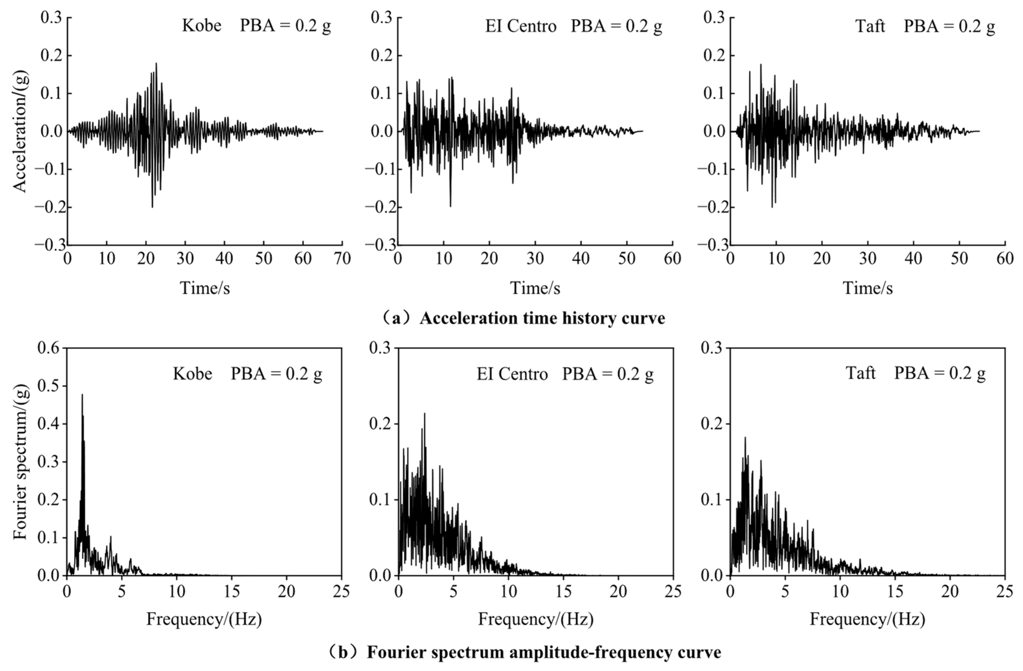
Based on the two-frequency control wave selection method proposed by the current ‘Code for Seismic Design of Buildings’ (GB50011-2010) [35], three different earthquake motions of Kobe earthquake, Taft earthquake, and El Centro earthquake are selected, and PBA (peak bedrock acceleration) is 0.1 g and 0.2 g, respectively. The acceleration time history and Fourier spectrum of three earthquake motions with different PBA are shown in Figure 3. It can be seen that compared with the El Centro earthquake and the Taft earthquake, the spectrum distribution of the Kobe earthquake is more concentrated, and the predominant frequency is the smallest. To make the bedrock earthquake motion effectively propagate to the foundation and structure, the size of the discrete element with spatial variation should be less than 1/10~1/8 of the minimum wavelength (the wavelength corresponding to the cut-off frequency) along the propagation direction of the earthquake motion [36].
In this paper, 25 Hz is taken as the cut-off frequency. The EW orientation of the seismic record is used as the earthquake motion input in the X-axis direction and input from the bottom of the model. The 3D nonlinear seismic response analysis has verified the effectiveness of the earthquake motion input method [37,38]. The ground stress (gravity) is applied to the station structure system before the earthquake motion. The finite element model of the structural system of a high-speed railway hub station, considering pile-soil interaction, is shown in Figure 4, Figure 5 and Figure 6. The numerical model employs a sufficiently small time step Δ t . In this study, we adopt Δ t = 10–5 s by the trial–and–error analysis to achieve the balance of computational efficiency and accuracy.

2.5. Cyclic Constitutive Model of Soil

In this paper, the generalized non-Masing model is used to describe the nonlinear hysteresis characteristics of soil under earthquake action [39,40,41,42]. The initial skeleton curve of the constitutive model is in the form of a hyperbola, as shown in Figure 7.
At the initial loading, the skeleton curve is expressed as follows:
τ = f ( γ ) = G γ = G max γ [ 1 H ( γ ) ]
In the formula
H ( γ ) = ( γ / γ r ) 2 B 1 + ( γ / γ r ) 2 B A
The shear modulus at time t can be expressed as follows:
G t = τ γ = G max 1 1 + 2 A B γ r 2 B γ 2 B + γ r 2 B H γ
According to the extended Masing rule, when the stress reverses, the expression of the shear stress-strain hysteresis curve in the subsequent loading process is the following:
τ τ rev 2 = f ( γ γ rev 2 ) = G max γ γ rev 2 1 H γ γ rev 2
The shear modulus at time t can be expressed as follows:
G t = τ τ rev γ γ rev = G max 1 1 + 2 A B 2 γ 0 2 B 2 γ 0 2 B + γ γ rev 2 B H γ γ rev 2
In the formula, τ is shear stress; G is the strain-related shear modulus; Gmax is the small strain shear modulus, which is determined by the density of soil ρ and the shear wave velocity Vs, that is Gmax = ρVs2; γ is shear strain; γr is the reference shear strain; A and B are dimensionless parameters, which can be determined by the best fitting of the hyperbolic curves of shear modulus ratio G/Gmax and damping ratio λ; τrev and γrev represent the shear stress and shear strain at the loading and unloading turning points, respectively. The constitutive model parameters of the site soil are shown in Table 2.

3. Natural Vibration Characteristics of the Hub Station Structure

3.1. Influence of Pile-Soil Interaction and the Base Frame Structure of the Station on the Natural Vibration Characteristics of the Roof Structure

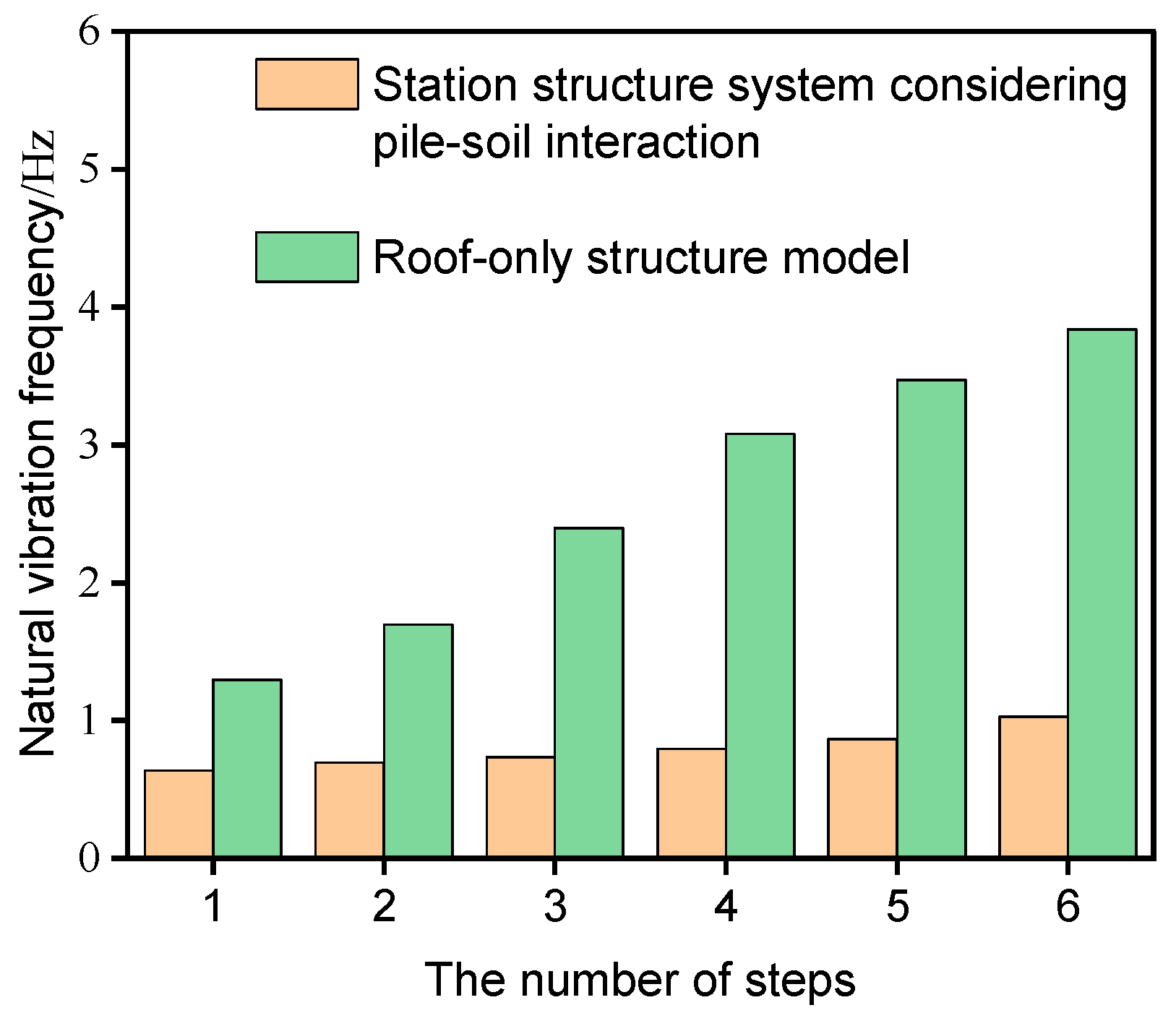
The modal analysis of the roof-only structure model and the structure system of the high-speed railway hub station, considering the pile-soil interaction, is carried out, respectively, and the influence of the pile-soil structure and the frame structure of the lower part of the station on the natural vibration characteristics of the upper roof structure is explored. In the modal analysis, the boundary conditions around and at the bottom of the model site soil are also improved with viscoelastic artificial boundaries. The first six natural vibration frequencies of the two structural systems are shown in Figure 8. It can be observed that the first six natural vibration frequencies of the two structures increase gradually, and the first six natural vibration frequencies of the high-speed railway hub station structure are significantly lower than those of the roof-only structure. This is because, in the process of natural vibration, the concrete frame structure under the high-speed railway station structure system, considering pile-soil interaction, vibrates together with the roof structure. The stiffness of the frame structure of the high-speed railway hub station is smaller than that of the foundation, while the roof structure is supported by the station frame structure. In the process of natural vibration, the boundary constraint supporting the roof is gradually weakened, and the stiffness of the station structure is gradually reduced. Coupled with the influence of the whipping effect, the natural vibration frequency of the station structure system becomes smaller. Therefore, it can also be seen that the structural system of a high-speed railway hub station, considering pile-soil interaction, presents the characteristics of ‘soft-upper-rigid-down’ as a whole.

3.2. Realization of Material Damping

In this paper, the Rayleigh damping formula is used to simulate the energy dissipation of the structure during the earthquake. An advanced Rayleigh damping coefficient determination method proposed by Hudson et al. [43] is used to represent the two coefficients of Rayleigh damping, which is called QUAD4M for short. Zou et al. [44] also carried out a comparison of various damping coefficient determination methods and found that the QUAD4M method has certain superiority and reliability. The expression of this method is as follows:
α = 2 ξ ω 1 ω 2 ω 1 + ω 2
β = 2 ξ ω 1 + ω 2
In the formula, ξ is the structural damping ratio, which is 5% in this paper; ω 1 is the circular frequency of the first vibration mode ( ω 1 = 2 π f 1 , f 1 is the first-order natural vibration of the high-speed railway station structure system); ω 2 = 2 π f 2 , f 2 = n f 1 , n is the nearest odd number greater than f e / f 1 , where f e is the basic frequency of earthquake motion. This method not only considers the frequency characteristics of structural vibration but also considers the spectral characteristics of the input earthquake motion.

4. Seismic Response Characteristics of High-Speed Railway Hub Station Structure System

4.1. Seismic Response of Pile-Soil System

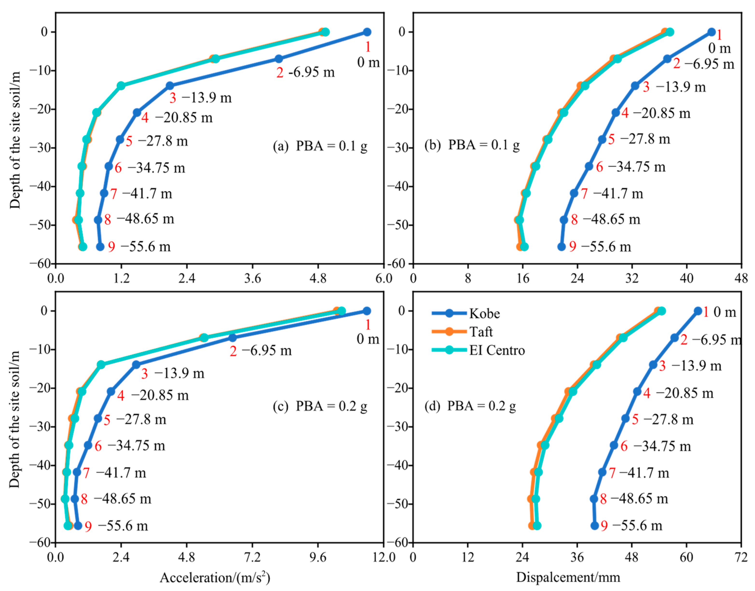
Figure 9 is the seismic response of the site soil at different depths under the action of three earthquake motions with different PBA. Combined with the detail drawing b in Figure 6, it can be seen that with the increase of the depth of the site soil from 0 m to 48.65 m, the acceleration and displacement responses of the site soil gradually decrease under the action of Kobe earthquake, Taft earthquake and El Centro earthquake with PBA of 0.1 g and 0.2 g.
The acceleration and displacement responses of the site soil decrease relatively large when the depth is from 0 m to 20.85 m. After 20.85 m, the decreased extent of acceleration and displacement response is reduced; In addition, the decreased extent of seismic response of the site soil under the action of the Taft earthquake and the El Centro earthquake is close to each other, and the decreased extent of seismic response of site soil under Kobe earthquake is greater than that of other two kinds of earthquake motions; The above is because, when the depth of the site soil gradually increases, the critical shear wave velocity of the soil gradually increases, the stiffness of the soil gradually increases, and the compactness of the soil gradually increases. Therefore, the same displacement of the site soil under the action of earthquake motion requires stronger earthquake motion, so the acceleration and displacement response of the site soil decrease with the increase of depth. When the depth of the site soil is small, the critical shear wave velocity of the soil is small, and the stiffness and compactness of the soil are small, so the acceleration and displacement response of the site soil under the action of earthquake motion is large; In addition, the seismic response of the site soil under the action of Kobe earthquake is reduced more than that of the other two earthquake motions. This phenomenon can be explained by the fact that compared with the other two kinds of earthquake motions, the predominant frequency of the Kobe earthquake is closer to the first-order natural vibration of the high-speed railway station structure system, which causes the resonance of the station structure system to a certain extent. Compared with the Taft earthquake and El Centro earthquake, the spectrum distribution of the Kobe earthquake is more concentrated, so the seismic response of the station structure system under the action of the Kobe earthquake decreases more. When the depth of the site soil increases from 48.65 m to 55.6 m, the acceleration and displacement responses of the site soil under the three earthquake motions with two PBA increase slightly. This is due to the inertia effect of the site soil when the depth of the site soil increases to a certain depth, so that the seismic response of the site soil increases slightly.
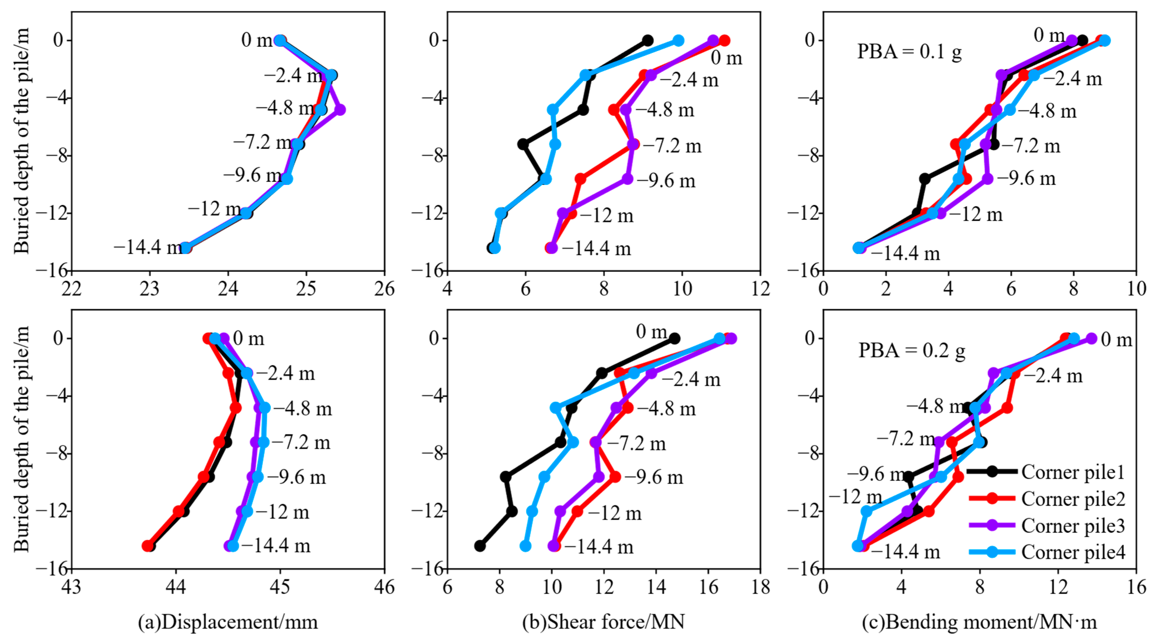
Figure 10 and Figure 11 are the seismic response characteristics of four corner piles and four side piles at the bottom under the action of the Kobe earthquake. It can be seen that under the action of Kobe earthquake with PBA of 0.1 g, the displacement responses of three piles in the four corner piles and side piles reach the maximum value at the buried depth of 2.4 m, and the shear force and bending moment responses at the top of all piles are the largest. When the buried depth increases from 4.8 m to 14.4 m, the seismic responses of corner piles and side piles decrease gradually, indicating that the interaction and common deformation between piles and soil can resist the deformation of the foundation under the action of earthquake motion. When the PBA increases to 0.4g, the peak displacement responses of three piles in the four corner piles and side piles appear at the buried depth of 4.8 m, and the shear force and bending moment responses at the top of all piles are also obviously the largest. When the buried depth increases from 4.8 m to 14.4 m, the seismic response of the corner piles and side piles also gradually decreases. It can be seen that the buried depth of the seismic response peak on the pile increases with the increase of the intensity of the earthquake motion, that is, the strength of the pile-soil interaction to resist the deformation of the foundation increases with the increase of the intensity of the earthquake motion [45,46,47,48]. In addition, it can be seen from Figure 10 that the seismic response of side pile 1 and side pile 2 is greater than that of side pile 3 and 4 under the action of the Kobe earthquake with the PBA = 0.1 g. This is because side pile 1 and side pile 2 are selected from the piles in the middle of both sides of the pile group, while side pile 3 and side pile 4 are selected from the piles in the middle of both sides of the front of the pile group. The position of the side pile distribution is shown in the detail drawing d in Figure 6 above. In the process of horizontal earthquake motion with PBA = 0.1 g, the inertial force is generally dominant, and side pile 1 and side pile 2 are more strongly affected by the soil on the left side of the site, so their seismic response is greater; when PBA reaches 0.2 g, the interaction strength between the four side piles and the site soil becomes larger, and the site deformation is dominant. Therefore, there is no phenomenon that the seismic response of side pile 1 and side pile 2 is greater than that of side pile 3 and side pile 4.

4.2. Seismic Response of Station Roof Structure

The seismic response characteristics of the roof members of the roof-only structure and the roof structure of the high-speed railway hub station, considering the pile-soil interaction under different PBA earthquake motions, are explored, respectively. By comparing the relative displacement of the member joints in the cross-section and longitudinal section of the roof of the two structures [43], the displacement response characteristics of the structural members are obtained. The seismic response characteristics of the structure are defined by the ratio of the difference between the seismic response peak value of the same node on the roof of the two structures and the seismic response peak value of the same node on the roof of the roof-only model under the action of earthquake motion. The formula for defining the characteristic coefficient is the following:
α = G a G r G r × 100 %
In the formula, and are the displacement response peak values of the same node on the roof of the high-speed rail hub station model and the roof-only model under the action of earthquake motion, respectively. The results obtained under three earthquake motions with different PBA are listed in Table 3 and Table 4, respectively.
The transverse, longitudinal, and vertical directions in the table represent the X-axis, Y-axis, and Z-axis directions in the numerical simulation, respectively. It can be seen from Table 3 and Table 4 that the transverse characteristic coefficients are smaller than the longitudinal and vertical ones, and the characteristic coefficients are all greater than 0. When the PBA is 0.1 g, the peak characteristic coefficients of the relative displacement response of the middle member nodes in the cross-section of the roof are 2.72~25.29% in the transverse direction, 140.99~243% in the longitudinal direction, and 220.88~743.13% in the vertical direction. The peak characteristic coefficients of the relative displacement response of the middle member nodes in the longitudinal section of the roof are 2.66~24.39% in the transverse direction, 1221.78~1568.15% in the longitudinal direction, and 2054.62%~5018.46% in the vertical direction; This is because the roof structure is supported by the lower concrete frame structure, and the frame structure will have an amplification effect on the received horizontal earthquake motion, increasing the inertial force of the upper roof structure. Therefore, the displacement of the roof mid-span member of the hub station structure increases, and the roof-only structure is not affected by the vibration of the lower structure, and the displacement of the member is relatively small. Under the action of three earthquake motions with PBA of 0.1 g and 0.2 g, the characteristic coefficients do not change significantly with the increase of earthquake motion intensity. Under the action of three kinds of earthquake motions, the concrete frame structure has an amplification effect on the displacement of the upper roof structure. The displacement response of the roof structure of the high-speed railway hub station, considering the pile-soil interaction, is significantly larger than that of the roof-only structure.

4.3. Seismic Response of Station Frame Structure

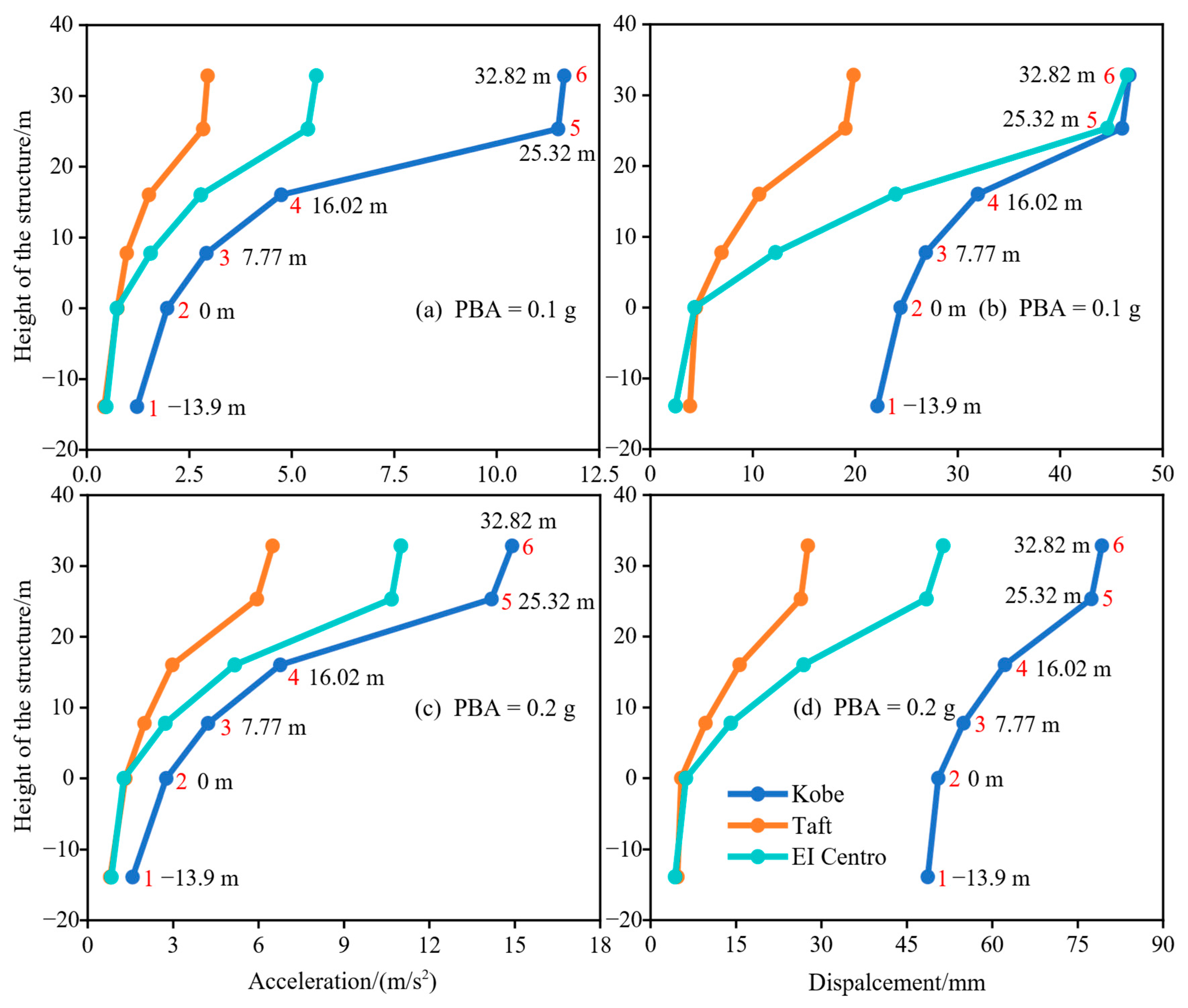
The response law of the frame structure of a high-speed railway hub station under three kinds of earthquake motions is analyzed. The results are explained by the schematic diagram of selecting points at different heights along the station frame structure shown in the detailed drawing c on Figure 6, and the variation of seismic response of the frame structure along the height of the structure under the earthquake motions with different PBA is shown in Figure 12, respectively. The depth of monitoring point 1 is 13.9 m below the surface, and the location of monitoring point 2 is the contact site between the first layer of the column and the surface, that is, the foundation height. The depth of monitoring point 1 is 13.9 m below the surface, and the location of monitoring point 2 is the contact site between the pillars on the first floor and the surface, that is, the foundation height. It can be seen from Figure 12 that as the height of the frame structure increases, the acceleration and displacement responses of the structure under the three earthquake motions with PBA of 0.1 g and 0.2 g gradually increase. The acceleration and displacement response of the foundation part is greater than the seismic response at 13.9 m below the surface. The acceleration and displacement response of the structure above the foundation under the action of the El Centro earthquake is greater than that of the Taft earthquake. This result also shows that compared with the Taft earthquake, the predominant frequency of the El Centro earthquake is closer to the natural vibration of the station structure system, and the spectrum distribution of the El Centro earthquake is more concentrated. The structural height increases from 7.77 m to 16.02 m, and then to 25.32 m. The increase in seismic response under different earthquake motions gradually increases. The acceleration and displacement response of the structure under three kinds of earthquake motions increases rapidly from the contact part between the pillars on the third floor and the floor to the contact part between the roof and the lower column. This is because the lower concrete frame structure and the upper roof structure interact with each other in the process of earthquake motion. As the height of the structure increases, the seismic response of the concrete frame structure increases rapidly. At the same time, it is also due to the whipping effect of the roof structure under the action of the earthquake motion. Therefore, its seismic response increases rapidly compared with the top of the concrete frame structure. The first layer of the frame structure has the lowest height and the largest number of columns, and the connection between the bottom of the column and the surface is also fixed. Therefore, the increase in seismic response from the foundation to the top of the first layer is the smallest.
In addition, compared with the results shown in Figure 9 above, it can be seen that the seismic response of the site soil along the depth under the action of the Taft earthquake and the El Centro earthquake is relatively close, and it can be seen from Figure 12 that the seismic response of the superstructure of the station under the action of the Taft earthquake and the El Centro earthquake is different. Therefore, it can be seen that the structure above the foundation of the high-speed railway hub station structure system is more sensitive to the spectral characteristics of the Taft earthquake and the El Centro earthquake than the site soil.
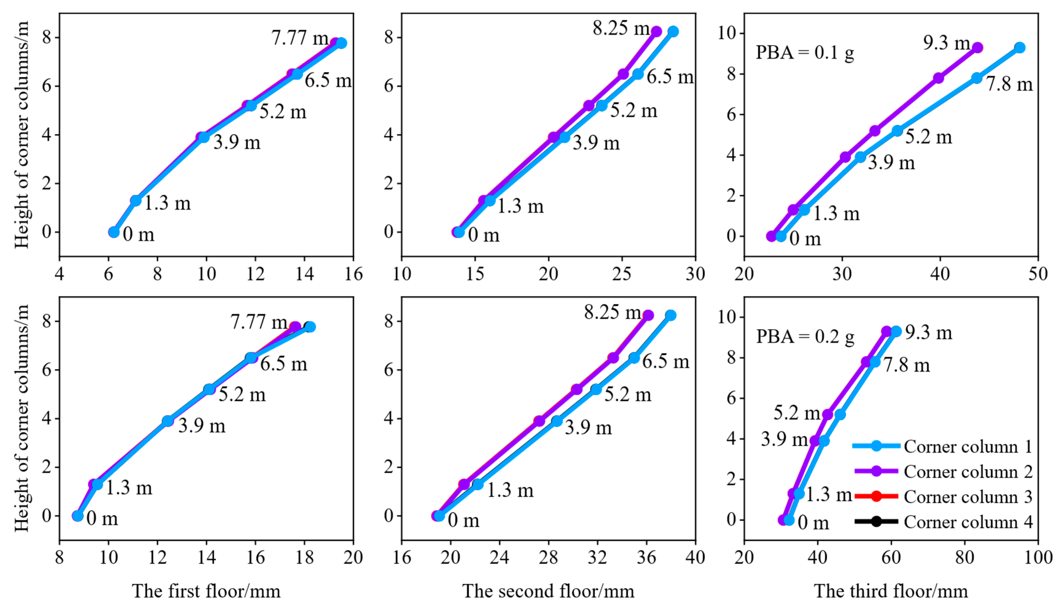
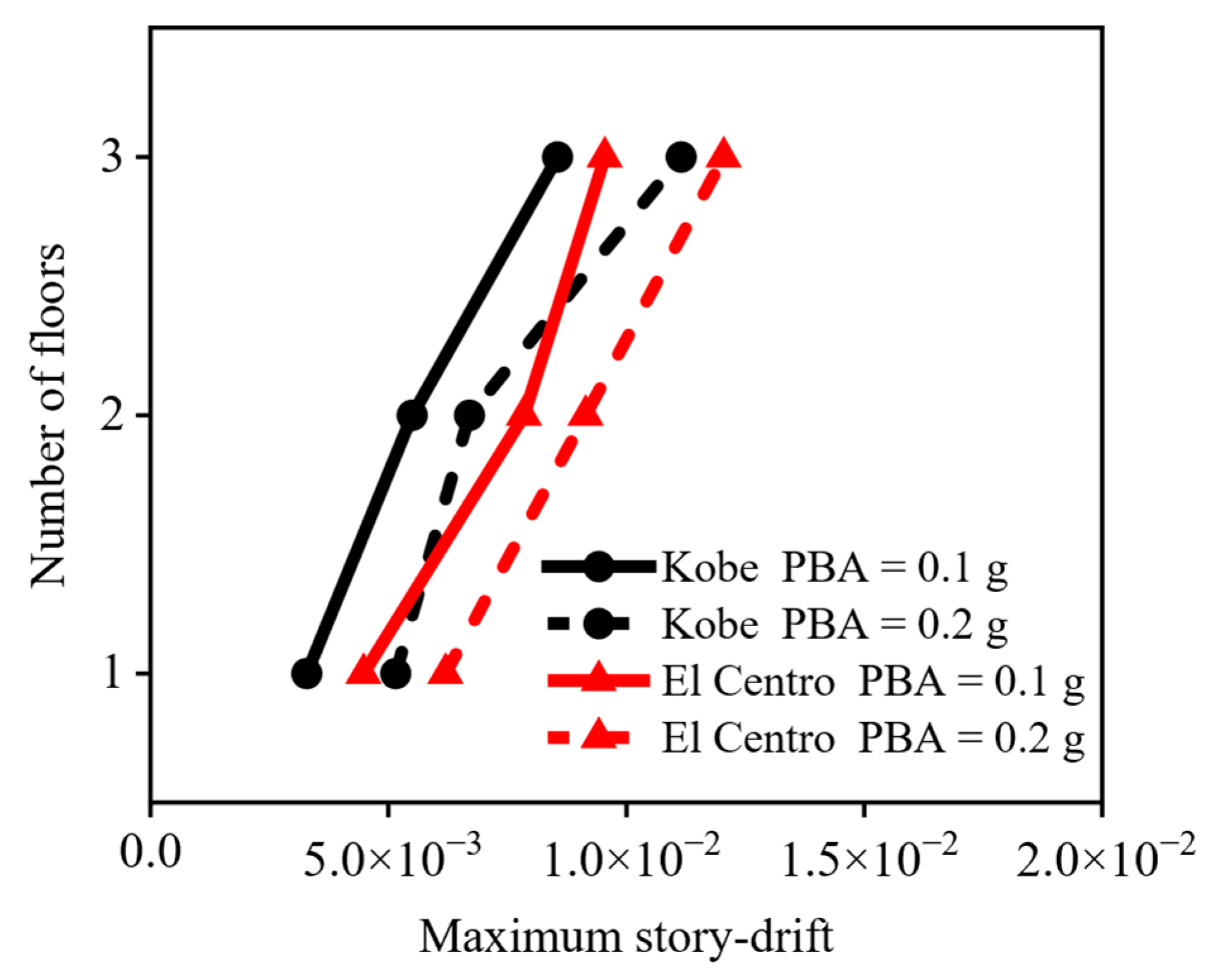
Figure 13 and Figure 14 show the displacement of the corner columns of each layer of the high-speed railway hub station structure under the action of two kinds of earthquake motions. It can be seen from the figures that under the action of the Kobe earthquake and the El Centro earthquake with two different PBA, the displacement of the corner columns of the three-layer frame structure increases gradually from the bottom to the top. Among them, the displacement growth rate of the third layer corner column above the column height of 3.9 m is significantly greater than that below 3.9 m. This is because the closer the component is to the upper steel roof under the action of earthquake motion, the faster the displacement increases. Figure 15 shows the variation law of the maximum story drift of each floor of the frame structure. It can be seen from Figure 15 that the maximum story drift of the station structure increases gradually under the action of the Kobe earthquake and the El Centro earthquake of different PBA. The maximum story drift of the top floor of the station is larger than the maximum story drift of the second floor. The maximum story drift of each layer of the station under the action of the El Centro earthquake is greater than the maximum story drift of each layer under the action of the Kobe earthquake. From the comparison of Figure 13 and Figure 14, it can be seen that the displacement value of the corner column of the three-story frame structure under the action of the Kobe earthquake is greater than the displacement value of the corresponding corner column under the action of the El Centro earthquake. Therefore, it can be seen that the story drift of the high-speed railway station structure has no obvious relationship with the intensity of earthquake motion.
In addition, in the ordinary concrete frame structure, the maximum story drift at the bottom is generally greater than the maximum story drift at the top. In the process of earthquake motion, the concrete frame structure under the high-speed railway hub station is affected by the seismic response of the upper roof structure, resulting in the top layer of the station being the part with the largest structural deformation. At the same time, the second layer structure is also slightly affected by the vibration deformation of the top layer structure, and the maximum story drift also increases accordingly. Therefore, the law of the maximum story drift of the concrete frame structure under the high-speed railway hub station system, considering the pile-soil interaction, is different from that of the common concrete frame structure.

5. Conclusions

In this paper, the three-dimensional nonlinear seismic response analysis of the Changde high-speed railway hub station structure is carried out, considering pile-soil interaction under different earthquake motion inputs. The main conclusions are as follows:
(1)
The pile-soil interaction has a significant influence on the dynamic characteristics of the high-speed railway hub station structure system. Due to the existence of the main frame structure, the natural vibration of the high-speed railway hub station system is significantly reduced compared with the roof-only structure.
(2)
Under the three earthquake motion records with PBA of 0.1 g and 0.2 g, the seismic response of the site soil gradually decreases with the increase of depth. The interaction between pile and soil resists the deformation of the foundation, and the nonlinear degree of pile-soil interaction increases with the increase of earthquake motion intensity.
(3)
Among the three kinds of earthquake motion records, the spectral characteristics of the Kobe earthquake are the closest to the natural vibration of a high-speed railway station structure system, followed by the El Centro earthquake. The displacement responses of the roof structure of Changde high-speed railway hub station, considering pile-soil interaction, are significantly larger than those without considering pile-soil interaction.
(4)
The roof structure has a significant effect on the seismic response of the base frame structure, and the seismic response of the connection between the roof structure and the base frame structure is seriously amplified. The seismic response of the high-speed railway station structure increases gradually with the increase in the height of the frame structure. The maximum story drift angle at the top floor of the station structure is also greater than that at the bottom floor.

Author Contributions

Conceptualization, N.Z. and Z.C.; methodology, N.Z.; software, N.Z.; validation, N.Z.; formal analysis, N.Z. and Z.C.; investigation, N.Z. and Z.C.; resources, N.Z.; data curation, N.Z.; writing—original draft preparation, Z.C.; writing—review and editing, Z.C.; visualization, N.Z.; supervision, N.Z.; project administration, N.Z.; funding acquisition, N.Z. All authors have read and agreed to the published version of the manuscript.

Funding

The research in this paper was funded by the National Key R&D Program of China (2023***3106500).

Data Availability Statement

The data that support the findings of this study are available from the corresponding author, upon reasonable request.

Acknowledgments

We are grateful to the High Performance Computing Center of Nanjing Tech University for supporting the computational resources.

Conflicts of Interest

The authors declare no conflict of interest.

References

  1. Sun, M.; Fan, F.; Zhi, X.; Kong, D. Analysis on dynamic response of quadrangular pyramid grid structure with supporting columns. China Civil. Eng. J. 2014, 47, 9–15. [Google Scholar]
  2. Sun, B.R. Shaking Table Test of “Integrated Station-Bridge” High-Speed Railway Station Structure; China University of Mining and Technology: Xuzhou, China, 2021. [Google Scholar]
  3. Su, L.; Dong, S.L. Seismic analysis of two typical spatial structures under multi-support vertical excitations. Eng. Mech. 2007, 24, 85–90. [Google Scholar]
  4. Liu, J.H.; Deng, H. Elasto-plastic dynamic response analysis for double-layer spherical reticulated shells under rare earthquake. J. Vib. Shock. 2012, 31, 161–167. [Google Scholar]
  5. Nakazawa, S.; Kato, S.; Yagi, Y. Evaluation of seismic damage of single layer lattice dome supported by ductile braces. J. Struct. Constr. Eng. 2012, 77, 593–601. [Google Scholar] [CrossRef]
  6. Nakazawa, S.; Yanagisawa, T.; Kato, S. Seismic loads for single layer reticular domes and seismic performance evaluation. J. Struct. Constr. Eng. 2014, 79, 1287–1297. [Google Scholar] [CrossRef]
  7. Jiang, S.F.; Li, H.J.; Long, T.T. Stability of single-layer three-way reticulated barrel vaults considering global geometric imperfection, member imperfection and eccentricity. Eng. Mech. 2022, 39, 178–188. [Google Scholar]
  8. Ye, Y.P. Analysis of dynamic characteristics and seismic performance of high-speed railway station structure. Rail. Cons. Tech. 2024, 10, 188–192. [Google Scholar]
  9. Palermo, A.; Krödel, S.; Matlack, K.H.; Zaccherini, R.; Dertimanis, V.K.; Chatzi, E.N.; Marzani, A.; Daraio, C. Hybridization of guided surface acoustic modes in unconsolidated granular media by a resonant metasurface. Phys. Rev. Appl. 2018, 9, 054026. [Google Scholar] [CrossRef]
  10. Ding, H.; Huang, N.; Xu, C.; Xu, Y.; Cao, Z.; Zeng, C.; Tong, L. A locally resonant metamaterial and its application in vibration isolation: Experimental and numerical investigations. Earthq. Eng. Struct. Dyn. 2024, 53, 15. [Google Scholar] [CrossRef]
  11. Yu, J.K. Dynamic Interaction Test and Numerical Simulation of Pile-Soil-Structure; The Institute of Engineering Mechanics, China Earthquake Administration: Harbin, China, 2023. [Google Scholar]
  12. Liu, J.Y.; Jing, L.P.; Qi, W.H. Analysis of dynamic interaction influence factors of pile-soil-structure. Earth. Eng. Eng. Dyn. 2024, 44, 210–221. [Google Scholar]
  13. Xu, S.Y. Study on Seismic Performance of Frame Structure Considering Pile Soil-Structure Interaction; Lanzhou Jiaotong University: Lanzhou, China, 2024. [Google Scholar]
  14. Wang, G.; Zhang, J.M.; Wei, X. Seismic response analysis of a subway station in liquefiable soil. Chin. J. Geotech. Eng. 2011, 33, 1623–1627. [Google Scholar]
  15. Muhammad; Lim, C.W.; Reddy, J.N. Built-up structural steel sections as seismic metamaterials for surface wave attenuation with low frequency wide bandgap in layered soil medium. Eng. Struct. 2019, 188, 440–451. [Google Scholar] [CrossRef]
  16. Zhuang, H.Y.; Hu, Z.H.; Wang, X.J.; Chen, G.X. Seismic response of a large underground structure in liquefied soils by FEM numerical modelling. Bull. Earth. Eng. 2015, 13, 3645–3688. [Google Scholar] [CrossRef]
  17. Zhuang, H.; Ren, J.; Miao, Y.; Jing, L.; Yao, E.; Xu, C. Seismic performance levels of a large underground subway station in different soil foundations. J. Earth. Eng. 2021, 25, 2808–2833. [Google Scholar] [CrossRef]
  18. Zhuang, H.; Wang, W.; Jin, L.; Li, S.; Chen, G. Seismic performance of two-story subway station structures with different isolating systems. Earth. Res. Adv. 2022, 2, 100155. [Google Scholar] [CrossRef]
  19. Zhuang, H.; Zhao, D.; Chen, G.; Wang, Y.; Zhao, K. Three-dimensional numerical investigation on seismic response of subway station in liquefied soil by the loosely coupled effective stress model. J. Earth. Eng. 2023, 27, 3607–3631. [Google Scholar] [CrossRef]
  20. Chen, G.X.; Chen, S.; Zuo, X.; Du, X.L.; Qi, C.Z.; Wang, Z.H. Shaking-table tests and numerical simulations on a subway structure in soft soil. Soil. Dyn. Earth. Eng. 2015, 76, 13–28. [Google Scholar]
  21. Chen, G.; Chen, S.; Qi, C.; Du, X.; Wang, Z.; Chen, W. Shaking table tests on a three-arch type subway station structure in a liquefiable soil. Bull. Earth. Eng. 2015, 13, 1675–1701. [Google Scholar] [CrossRef]
  22. Chen, G.; Wang, Y.; Zhao, D.; Zhao, K.; Yang, J. A new effective stress method for nonlinear site response analyses. Earthq. Eng. Struct. Dyn. 2021, 50, 1595–1611. [Google Scholar] [CrossRef]
  23. Chen, G.; Wang, Y.; Zhao, D.; Zhao, K.; Yang, J. 3D seismic response characteristics of a pile-mat-founded AP1000 nuclear-island building considering nonlinear hysteretic behavior of soil. Bull. Earth. Eng. 2022, 20, 7077–7106. [Google Scholar] [CrossRef]
  24. Wang, G.B.; Hao, P.F.; Sun, F.X. Spatial influence scope of end wall of metro station structures. Chin. J. Geotech. Eng. 2020, 42, 1435–1445. [Google Scholar]
  25. Jing, Y.; Zhuang, H.Y.; Wang, W.; Zhou, Z.H.; Chen, G.X. Seismic performance and effective isolation of a large multilayered underground subway station. Soil. Dyn. Earth. Eng. 2021, 142, 106560. [Google Scholar] [CrossRef]
  26. Zhao, K.; Xia, G.X.; Wang, Y.Z.; Zhao, D.F.; Zhuang, H.Y.; Chen, G.X. Three-dimensional loosely coupled effective stress method for seismic soil-structure interactions. Chin. J. Geotech. Eng. 2022, 44, 861–869. [Google Scholar]
  27. Gholizadeh, S.; Milany, A.; Hasancebi, O. Seismic optimization and performance assessment of special steel moment-resisting frames considering nonlinear soil-structure interaction. Steel Comp. Str. 2023, 47, 339–353. [Google Scholar]
  28. Zhu, S.D.; Chen, G.X.; Chen, W.Y.; Gao, W.S.; Li, W.B. Influence of soil secondary nonlinearity on 3D seismic responses of a pile-founded nuclear island structure. Rock. Soil. Mech. 2023, 44, 1501–1511. [Google Scholar]
  29. Song, Z.W. Research on the structure design for the central station track level of newly built Shenyang South railway station. J. Rail. Eng. Soc. 2014, 31, 81–86. [Google Scholar]
  30. Zhang, L.L.; Xu, J.H.; Zhang, Y.Y.; Sun, B.R.; Wang, Y. Seismic vulnerability analysis of “integrated station-bridge” high-speed railway station structure based on IDA. Earth. Resistant Eng. Retro. 2023, 45, 86–94. [Google Scholar]
  31. Zhao, K.; Zhu, S.; Bai, X.; Wang, Q.; Chen, S.; Zhuang, H.; Chen, G. Seismic response of immersed tunnel in liquefiable seabed considering ocean environmental loads. Tunn. Undergr. Space Technol. 2021, 115, 104066. [Google Scholar] [CrossRef]
  32. Zhao, K.; Wang, Q.; Chen, S.; Zhuang, H.; Chen, G. Dynamic response of pipelines in liquefiable seabed under nature loadings: Waves and currents. Ocean. Eng. 2021, 230, 109051. [Google Scholar] [CrossRef]
  33. Zhang, X.L.; Li, X.J.; Chen, G.X.; Zhou, Z.H. An improved method of the calculation of equivalent nodal forces in viscous-elastic artificial boundary. Chin. J. Theor. Appl. Mech. 2016, 48, 1126–1135. [Google Scholar]
  34. Chen, G.; Ruan, B.; Zhao, K.; Chen, W.; Zhuang, H.; Du, X.; Khoshnevisan, S.; Juang, C.H. Nonlinear response characteristics of undersea shield tunnel subjected to strong earthquake motions. J. Earth. Eng. 2020, 24, 351–380. [Google Scholar] [CrossRef]
  35. GB50011-2010; Code for Seismic Design of Buildings. China Architecture & Building Press: Beijing, China, 2010; pp. 23–25.
  36. Kuhlemeyer, R.L.; Lysmer, J. Fine element method accuracy for wave propagation problems. J. Soil. Mech. Found. Div. 1973, 99, 421–427. [Google Scholar] [CrossRef]
  37. Zhu, S.D.; Chen, G.X.; Jiang, P.C.; Chen, W.Y.; Gao, W.S. 3D nonlinear response characteristics of the pile-raft-supported AP1000 nuclear island building in soft deposits subjected to strong earthquake motions. Eng. Mech. 2021, 38, 129–142. [Google Scholar]
  38. Zhu, S.D.; Chen, G.X.; Chen, W.Y.; Gao, W.S. 3D seismic response characteristics of piles of a nuclear island building considering nonlinearity of soil. China Civil. Eng. J. 2023, 56, 124–136. [Google Scholar]
  39. Zhao, D.F.; Ruan, B.; Chen, G.X.; Xu, L.Y.; Zhuang, H.Y. Validation of modified irregular loading-unloading rules based on Davidenkov skeleton curve and its equivalent shear strain algorithm implemented in ABAQUS. Chin. J. Geotech. Eng. 2017, 39, 888–895. [Google Scholar]
  40. Wang, Y.Z.; Zhao, D.F.; Chen, G.X.; Liang, K. A new nonlinear effective stress method for one-dimensional seismic site response analysis and its validation. Chin. J. Geotech. Eng. 2021, 43, 502–510. [Google Scholar]
  41. Chen, W.; Luo, Z.; Zheng, Y.; Xu, L.; Huang, L. Seismic response analysis of liquefiable seabed sites: Effects of seawater-seabed interaction and bidirectional seismic motion. Ocean. Eng. 2025, 324, 120717. [Google Scholar] [CrossRef]
  42. Zhuang, H.Y.; Li, X.X.; Zhao, K.; Wu, S.L.; Li, Z.Y.; Chen, G.X. Liquefaction-induced lateral spreading characteristics of the fluvial terraces at the lower reaches of Yangtze River. Eng. Geol. 2025, 346, 107900. [Google Scholar]
  43. Hudson, M.; Idriss, I.M.; Beikae, M. User Manual for QUAD4m: A Computer Program to Evaluate the Seismic Response of Soil Structures Using Finite Element Procedures and Incorporating A Compliant Base; University of California: Berkeley, CA, USA, 1994. [Google Scholar]
  44. Zou, D.G.; Xu, B.; Kong, X.J. Study of influence of different methods for calculating Rayleigh damping coefficient on high earth-rock dam seismic response. Rock. Soil. Mech. 2011, 32, 797–803. [Google Scholar]
  45. Bagheri, M.; Jamkhaneh, M.E.; Samali, B. Effect of seismic soil-pile-structure interaction on mid-and high-rise steel buildings resting on a group of pile foundations. Int. J. Geomech. 2018, 18, 04018103.1–04018103.27. [Google Scholar] [CrossRef]
  46. Asgari, A.; Bagheri, M.; Hadizadeh, M. Advanced seismic analysis of soil-foundation-structure interaction for shallow and pile foundations in saturated and dry deposits: Insights from 3D parallel finite element modeling. Structures 2024, 69, 107503. [Google Scholar] [CrossRef]
  47. Asgari, A.; Sorkhi, S.F.A. Wind turbine performance under multi-hazard loads: Wave, wind, and earthquake effects on liquefiable soil. Results Eng. 2025, 26, 104647. [Google Scholar] [CrossRef]
  48. Asgari, A.; Ranjbar, F.; Bagheri, M. Seismic resilience of pile groups to lateral spreading in liquefiable soils: 3D parallel finite element modeling. Structures 2025, 74, 108578. [Google Scholar] [CrossRef]
Figure 1. Equivalent nodal force and viscoelastic artificial boundary.
Buildings 15 02466 g001
Figure 2. Validation of viscoelastic artificial boundary.
Buildings 15 02466 g002
Figure 3. Acceleration time history and Fourier spectrum of earthquake motion input from bedrock.
Buildings 15 02466 g003
Figure 4. Front schematic diagram of the high-speed railway station structure.
Buildings 15 02466 g004
Figure 5. Schematic diagram of the layout of the pier cap and group piles.
Buildings 15 02466 g005
Figure 6. Schematic diagram of a finite element model of a high-speed railway hub station structure system, considering pile-soil interaction and its partial detail diagram.
Buildings 15 02466 g006
Figure 7. Constitutive model diagram of site soil.
Buildings 15 02466 g007
Figure 8. Comparison of the first six-order natural vibration frequencies of structural systems.
Buildings 15 02466 g008
Figure 9. Seismic responses of site soil along depth under the action of earthquake vibration with different PBA.
Buildings 15 02466 g009
Figure 10. Seismic responses of four corner piles under the action of the Kobe earthquake.
Buildings 15 02466 g010
Figure 11. Seismic responses of four side piles under the action of the Kobe earthquake.
Buildings 15 02466 g011
Figure 12. Seismic responses of the frame structure vs. the height of the structure under the action of earthquake motion with different PBA.
Buildings 15 02466 g012
Figure 13. Displacement of four corner columns in each layer under the action of the Kobe earthquake.
Buildings 15 02466 g013
Figure 14. Displacement of four corner columns in each layer under the action of the El Centro earthquake.
Buildings 15 02466 g014
Figure 15. Maximum story drift of the station structure under the action of two kinds of earthquake motions.
Buildings 15 02466 g015
Table 1. Constitutive model parameters of concrete and steel.
ConstituentDensity /(kg/m3)Elastic Modulus
/(GPa)
Poisson RatioUltimate Tensile Strength /(MPa)Ultimate Tensile StrainUltimate Compressive Strength /(MPa)Peak Compressive StrainLimit Compressive Strain
C40 concrete250032.50.22.397.35 × 10–526.80.0020.0033
Steel79002100.36500.184200.0020.02
Table 2. Constitutive model parameters of soil layer.
Constituent.Category of SoilsDepth/
(m)
Density/
(kg/m3)
Shear Wave Velocity/
(m/s)
Poisso RatioABReference Shear StrainDamping
Ratio Under Small Strain
Surface layerBackfill2.619001760.471.050.420.000310.025
Middle layerClay14.619502360.451.060.440.000530.024
SublayerMealy sand33.620002890.431.070.460.000820.022
Bottom layerSandy
soil 1
50.620304580.431.100.470.000930.020
Sandy
soil 2
55.620455460.421.120.450.001110.019
Table 3. Relative displacement response peak values of mid-span member joints in cross-section.
ConstituentCategory
of Soils
PBA = 0.1 gPBA = 0.2 g
KobeTaftEl CentroKobeTaftEl Centro
TransverseCharacteristic
coefficient/(%)
2.725.8625.293.295.4818.46
LongitudinalCharacteristic
coefficient/(%)
243140.99166.80315139.70165.86
VerticalCharacteristic
coefficient/(%)
220.88743.13570.43146.42639.52411.56
Table 4. Relative displacement response peak values of mid-span member joints in the longitudinal section.
ConstituentCategory
of Soils
PBA = 0.1 gPBA = 0.2 g
KobeTaftEl CentroKobeTaftEl Centro
TransverseCharacteristic
coefficient/(%)
2.665.5224.393.255.4718.16
LongitudinalCharacteristic
coefficient/(%)
1458.121221.781568.152025.691175.471519
VerticalCharacteristic
coefficient/(%)
2054.625018.464419.7311994326.493164.91
Disclaimer/Publisher’s Note: The statements, opinions and data contained in all publications are solely those of the individual author(s) and contributor(s) and not of MDPI and/or the editor(s). MDPI and/or the editor(s) disclaim responsibility for any injury to people or property resulting from any ideas, methods, instructions or products referred to in the content.