

Seismic Behavior and Resilience of an Endplate Rigid Connection for Circular Concrete-Filled Steel Tube Columns


Abstract
1. Introduction
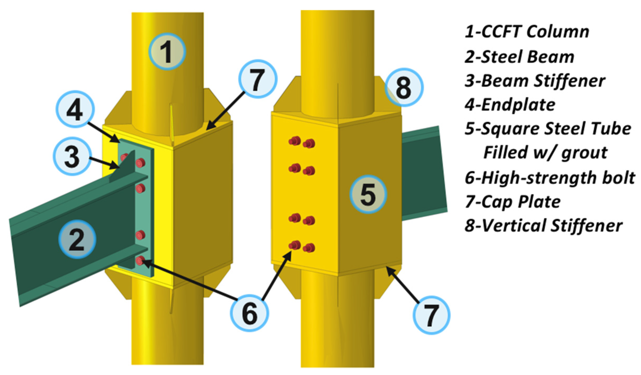
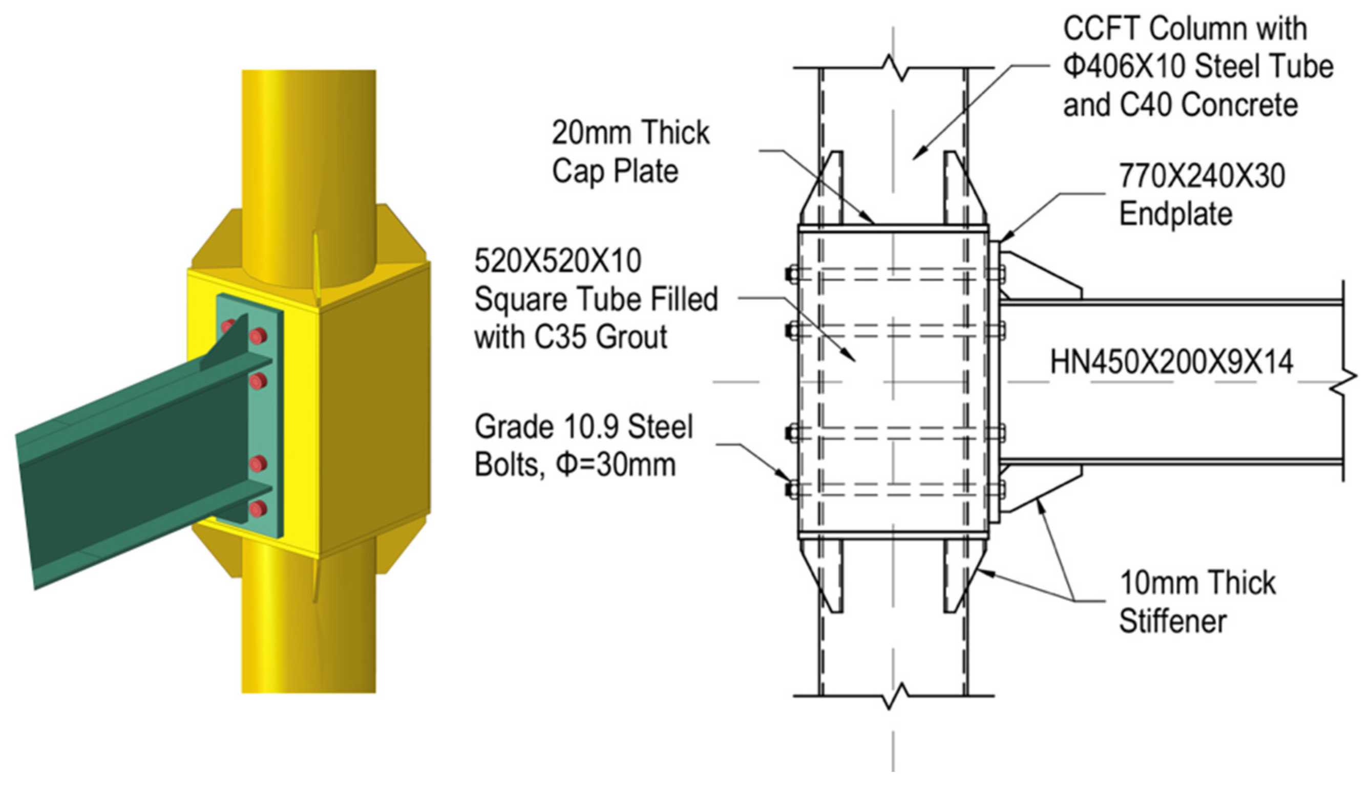
2. Design Concept
3. Prototype Connection
4. Quasi-Static Test
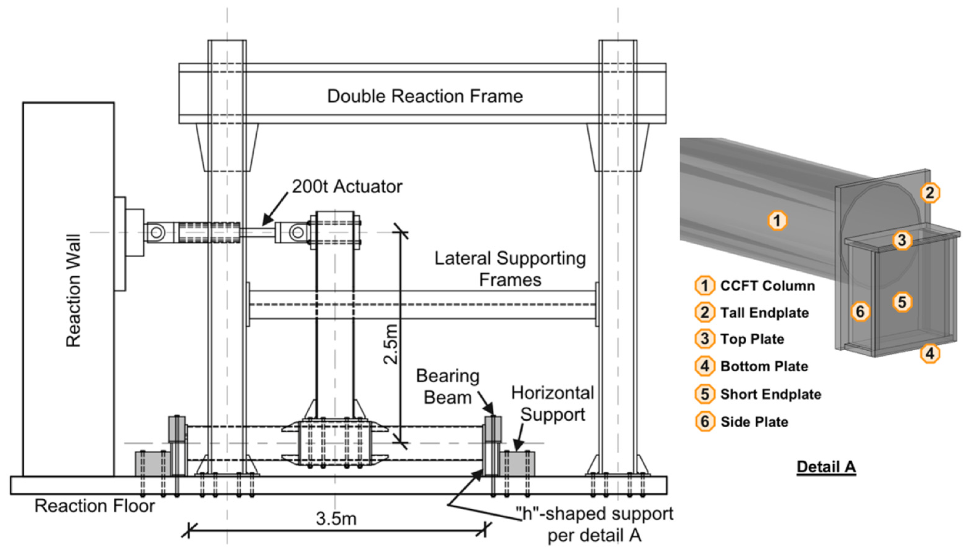
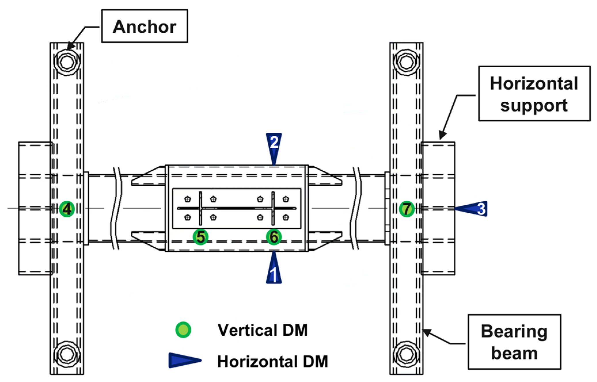
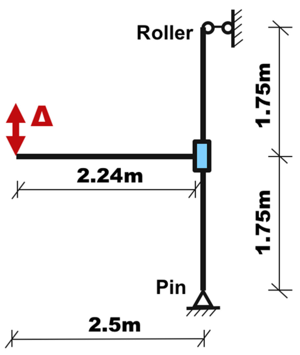
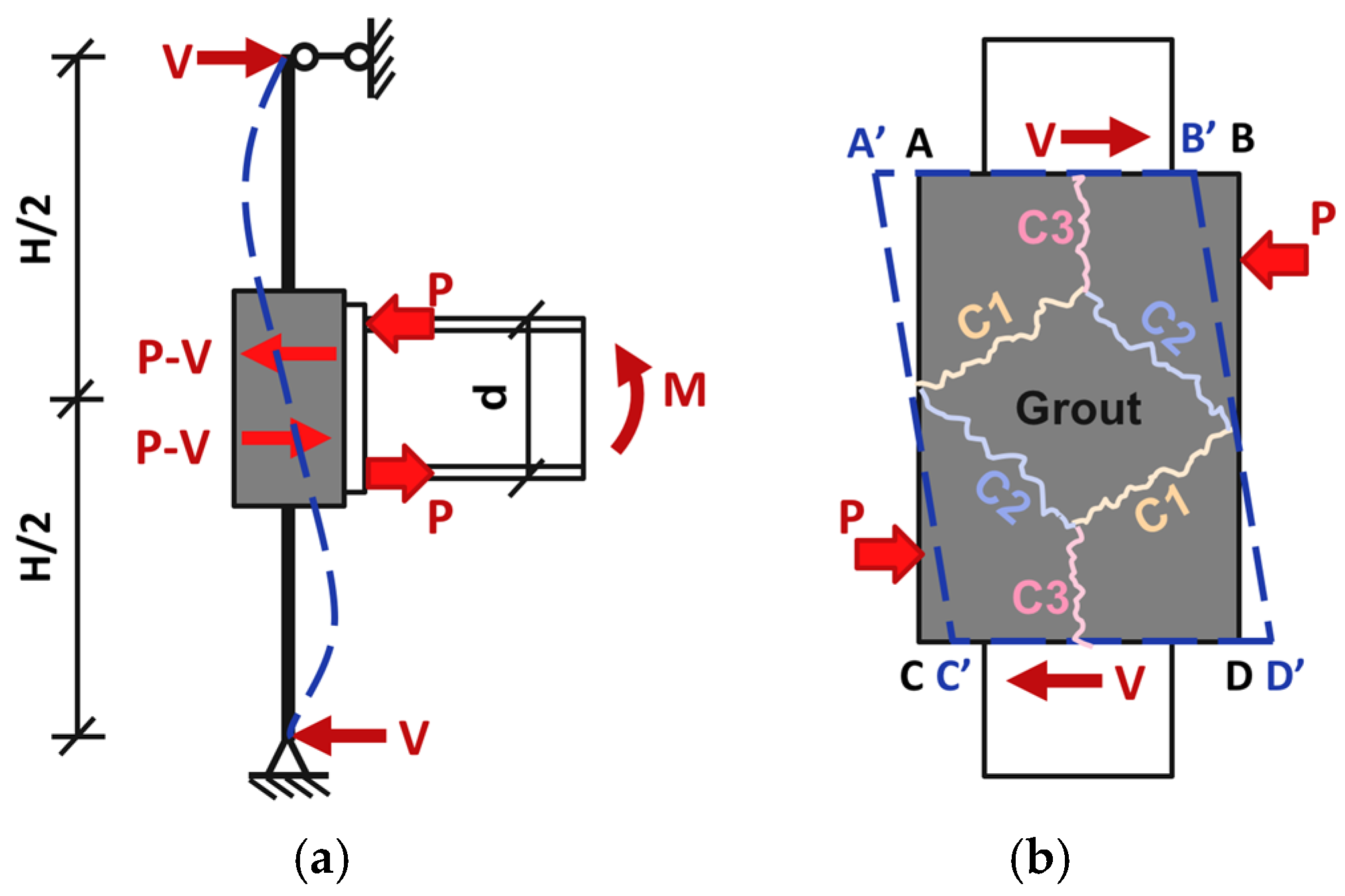
4.1. Test Method
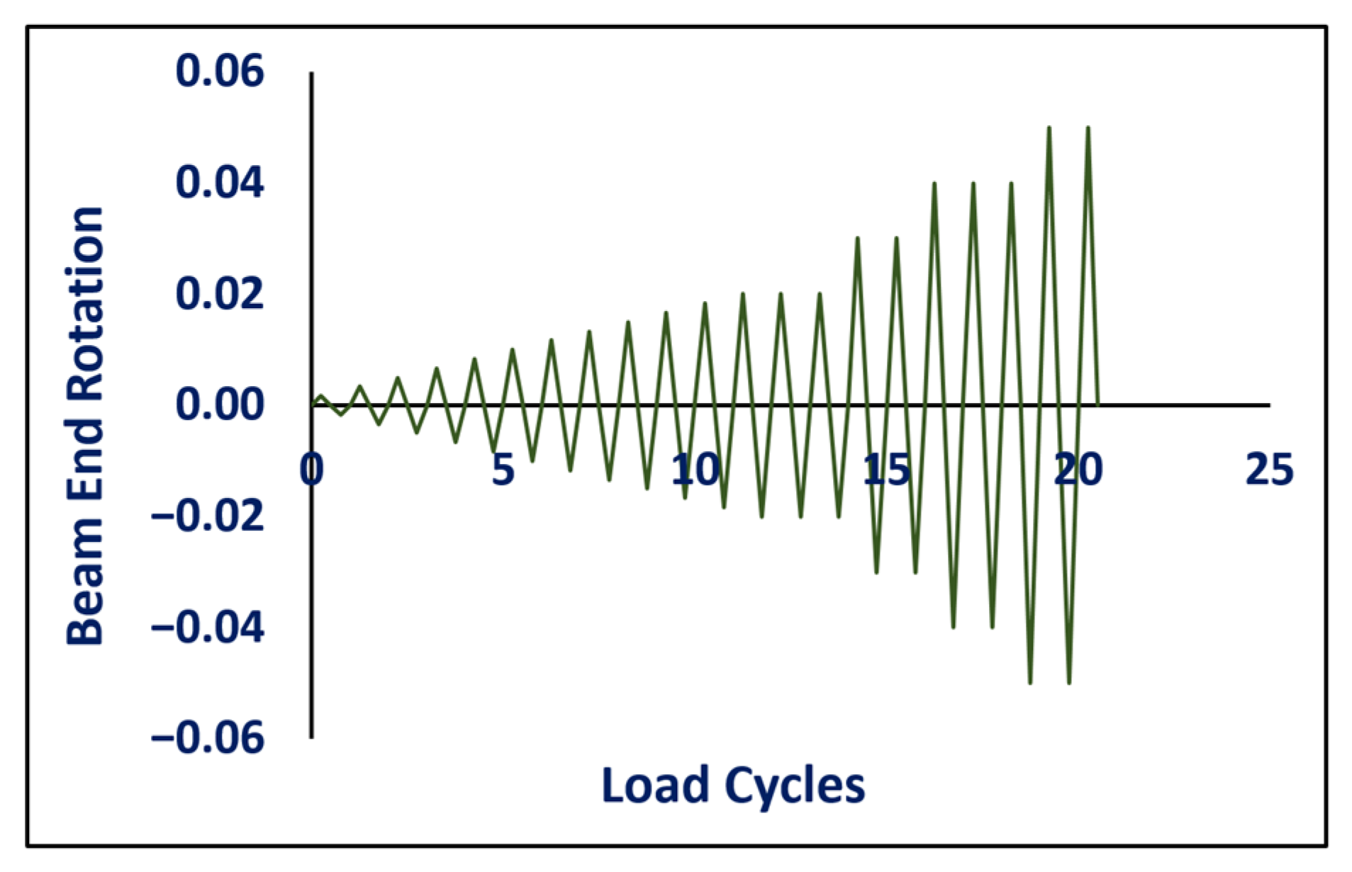
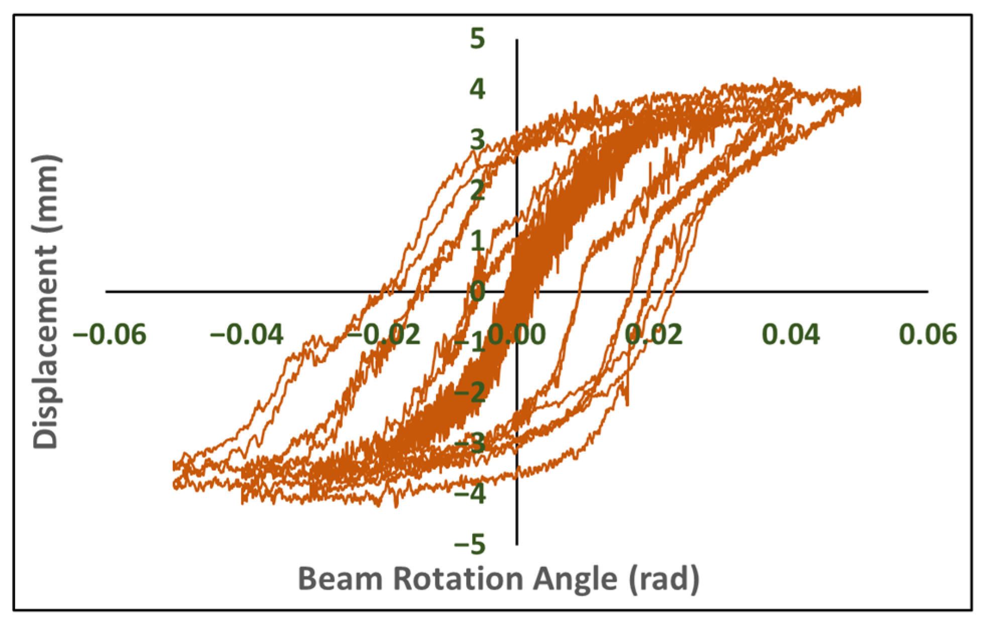
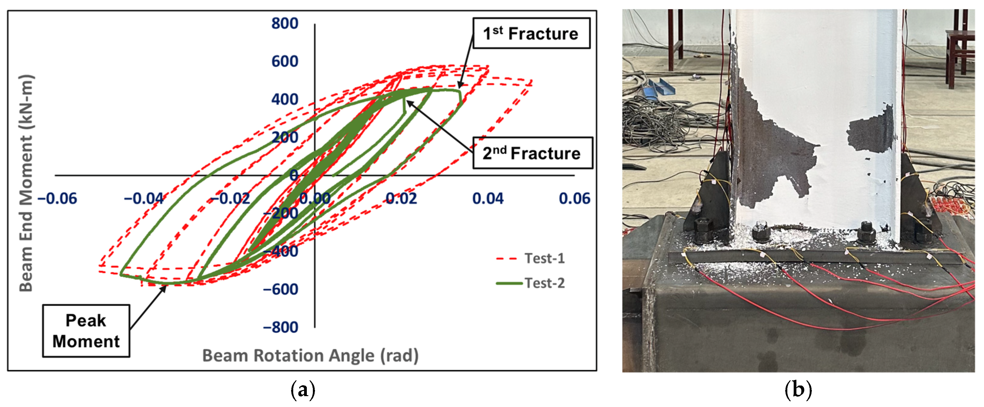
4.2. Test Results
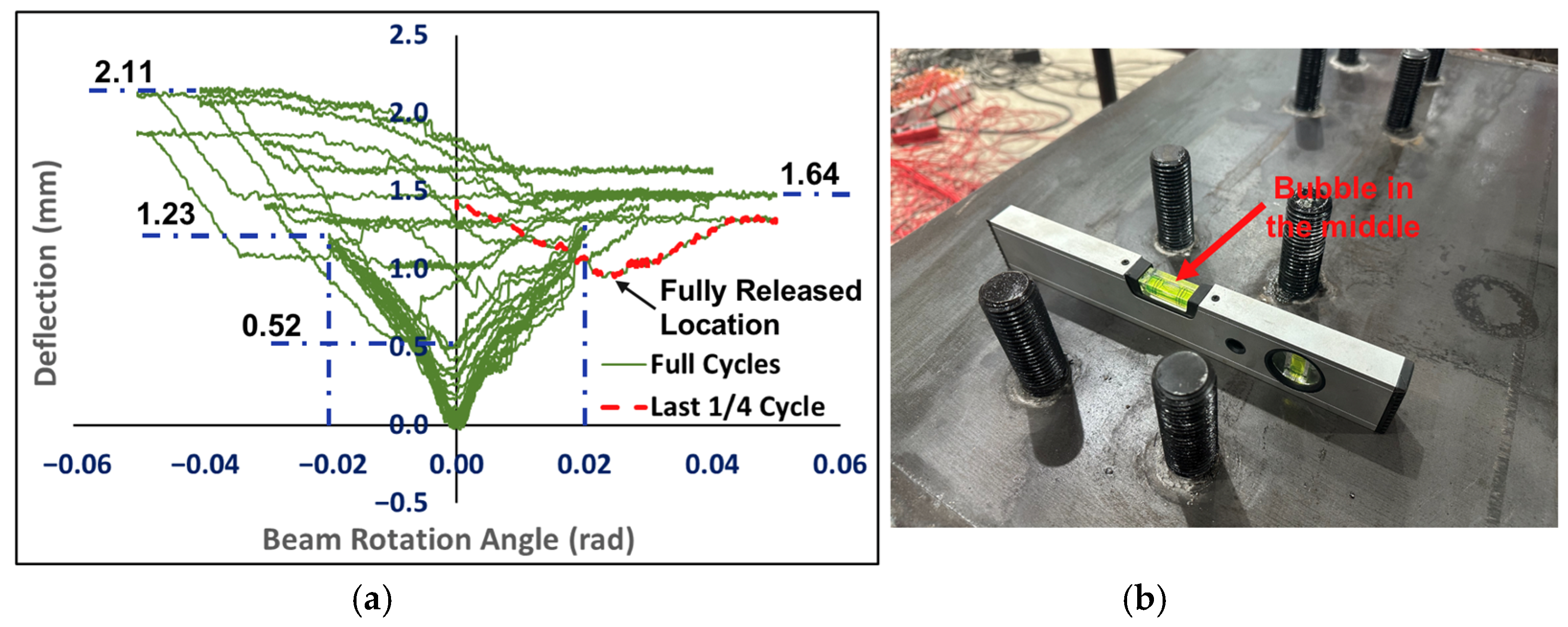
4.2.1. Test-1
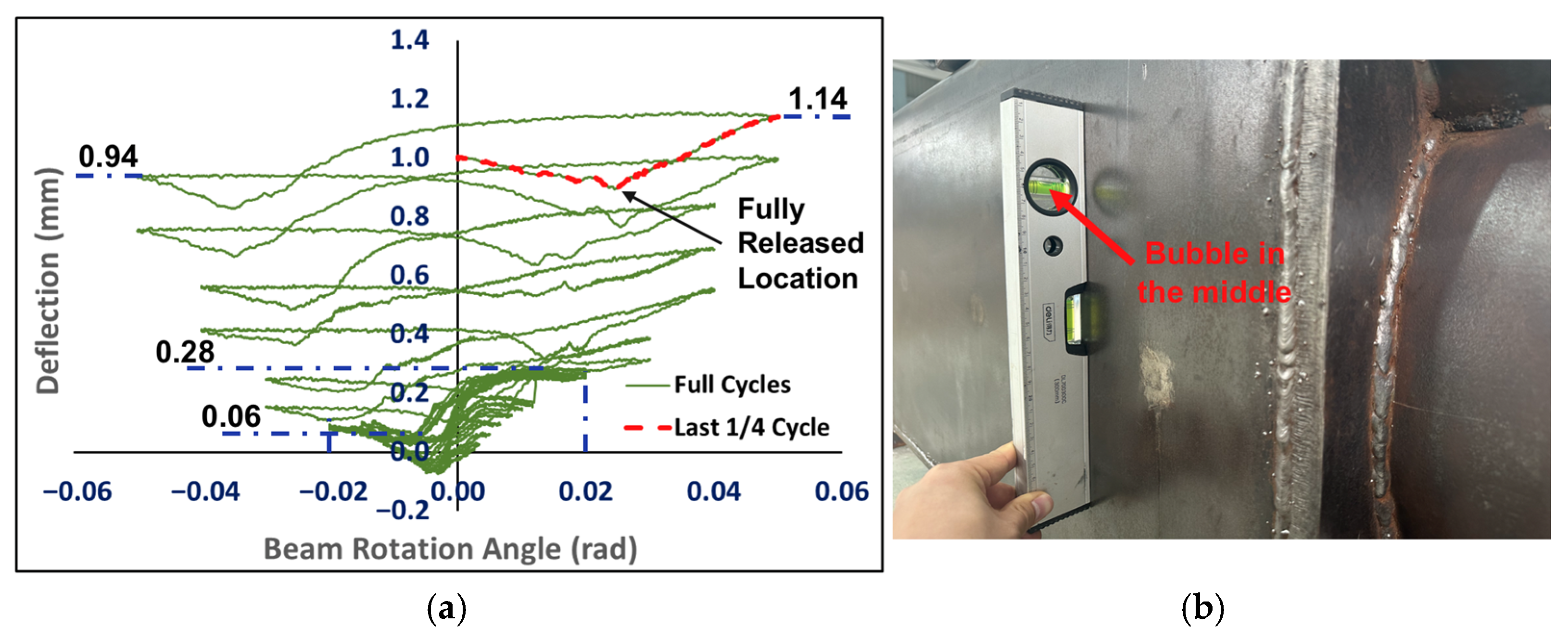
4.2.2. Test-2
5. Finite Element Analysis
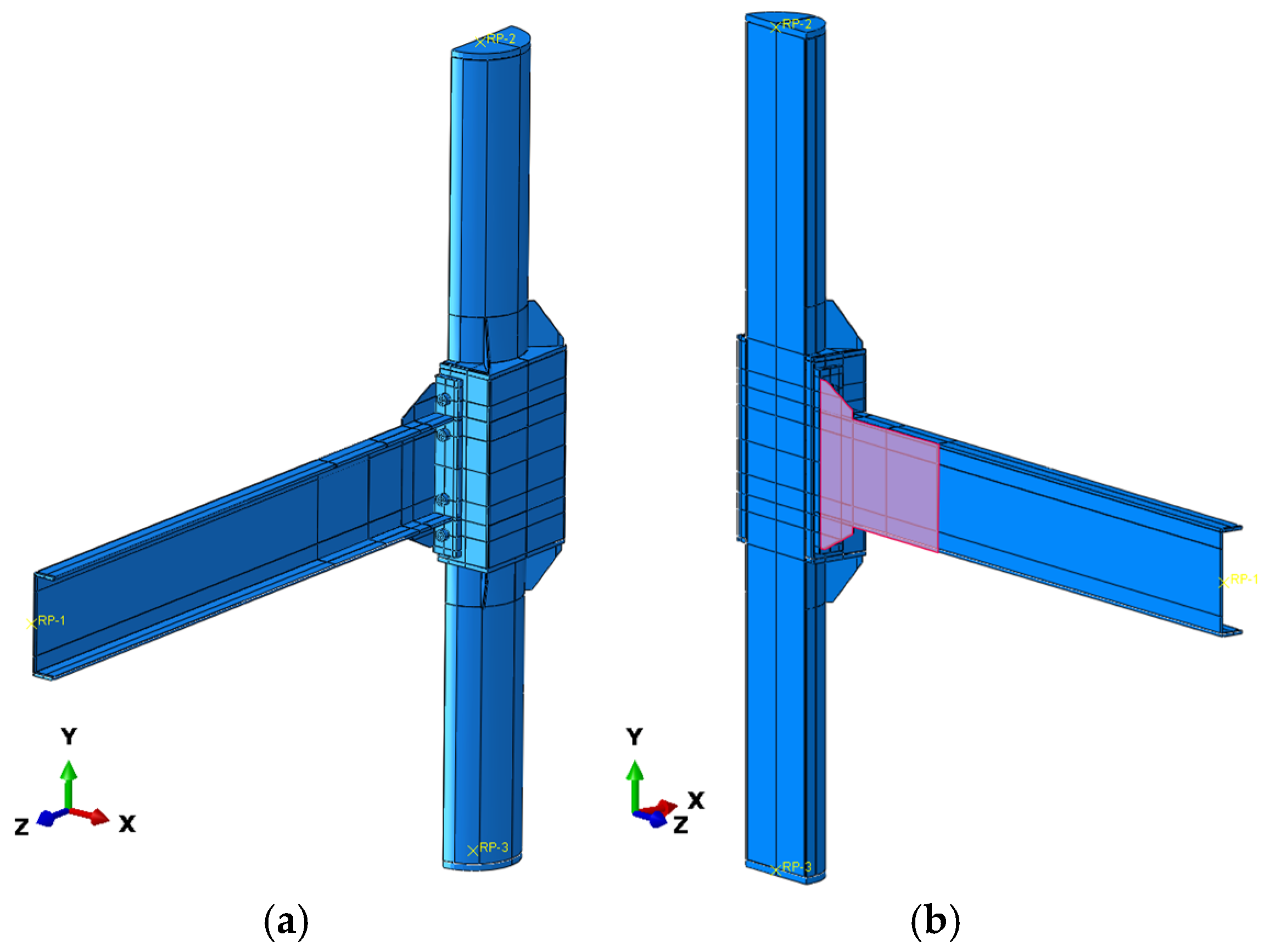
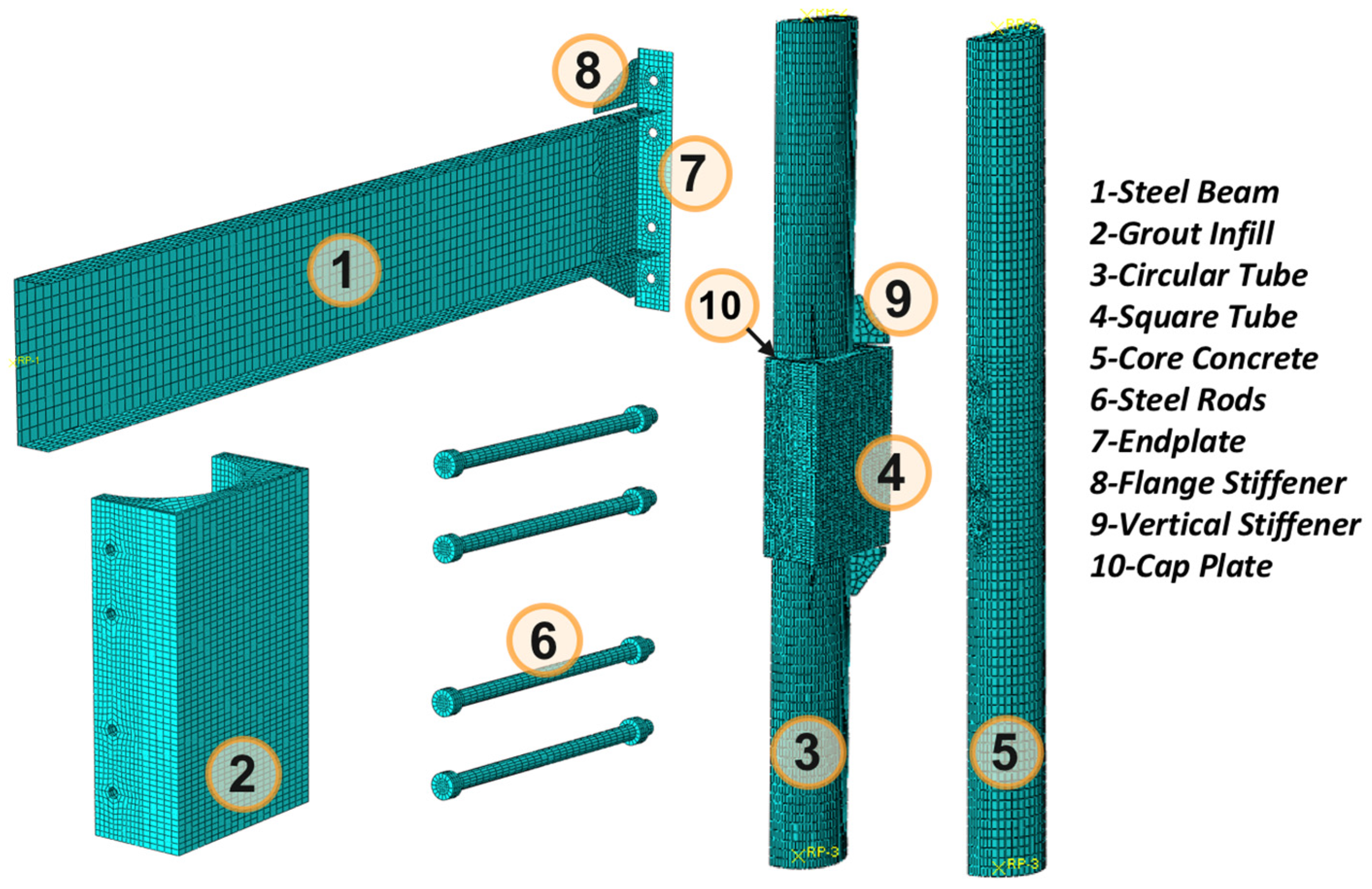
5.1. FEA Model
- ○
- : Ratio of prism strength to cube strength. It is 0.76 for ordinary concrete with strength grade C50 and below, 0.82 for high-strength concrete with strength grade C80 and above, and linearly interpolated for intermediate grades.
- ○
- : Brittleness reduction coefficient. It is 1.0 for ordinary concrete with strength grade C40 and below, 0.87 for high-strength concrete with strength grade C80 and above, and linearly interpolated for intermediate grades.
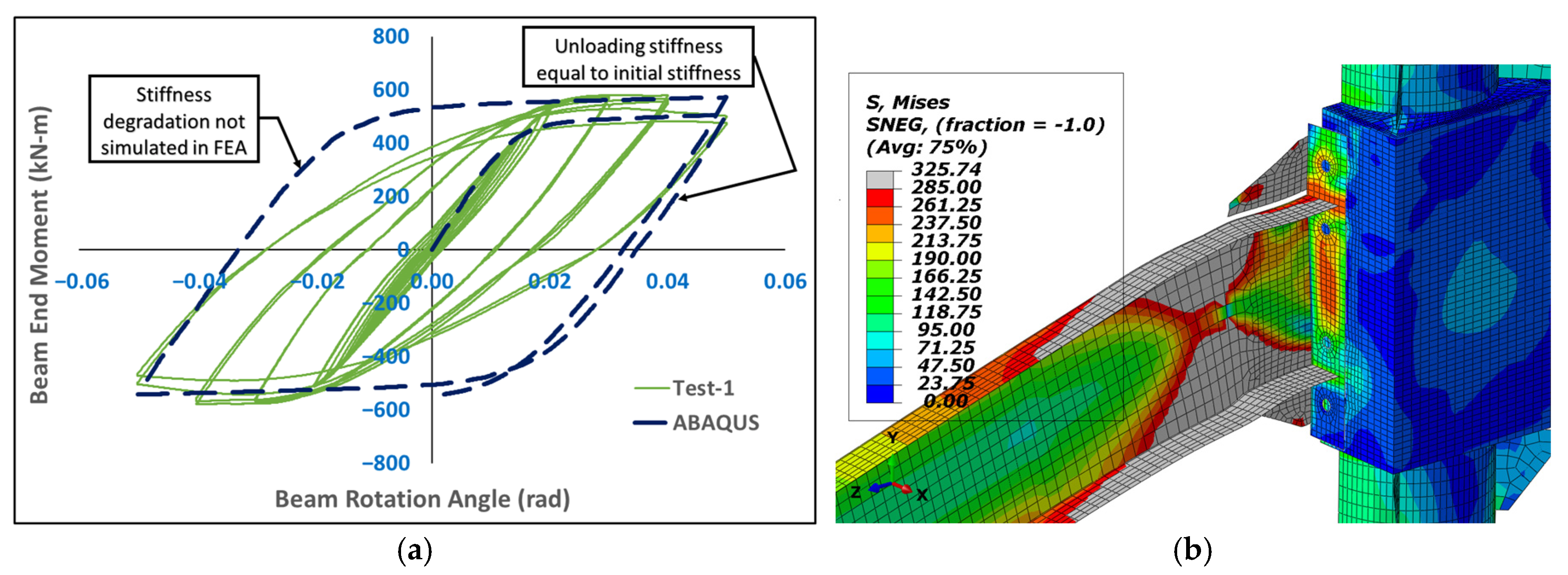
5.2. Model Verification
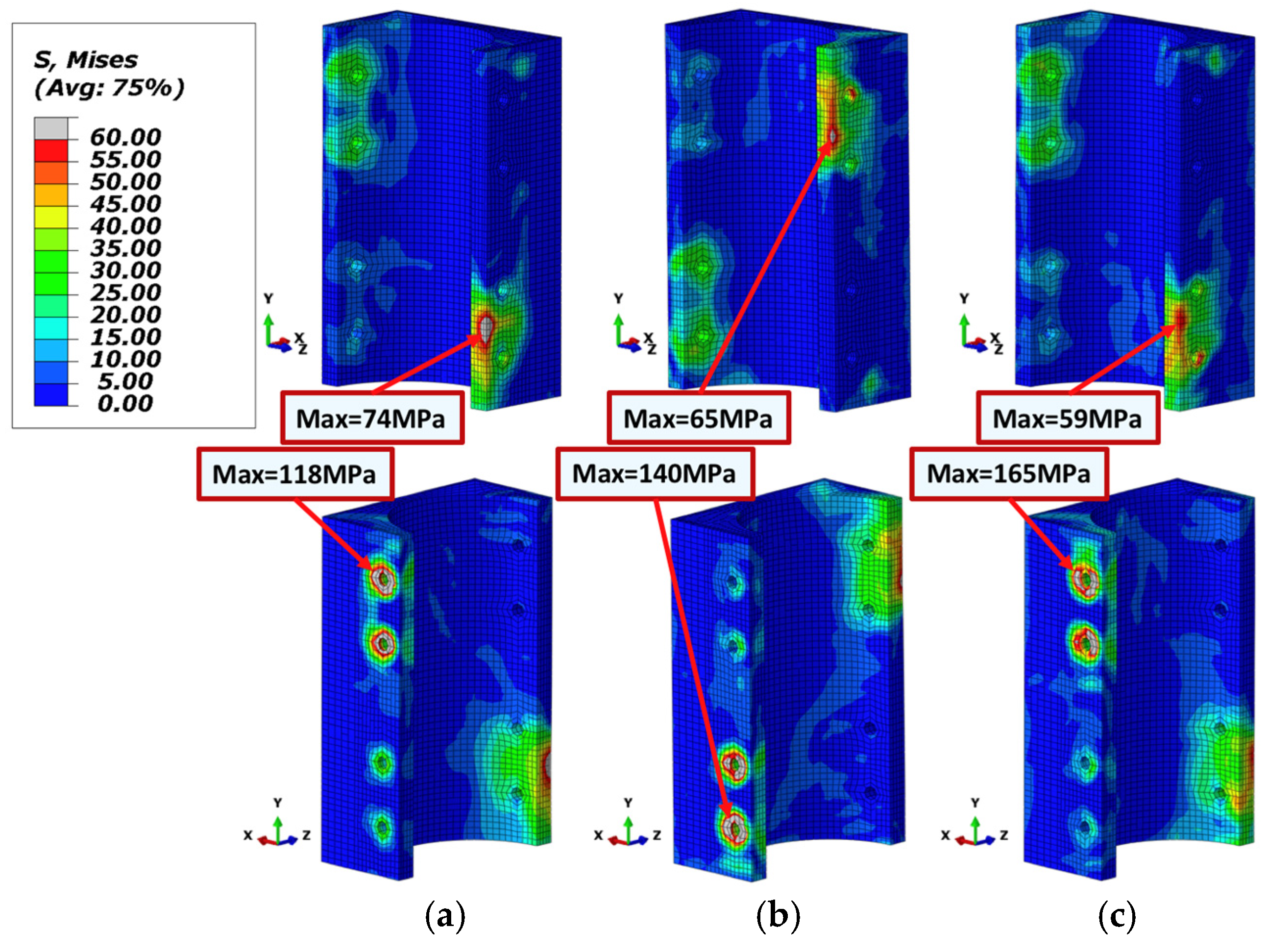
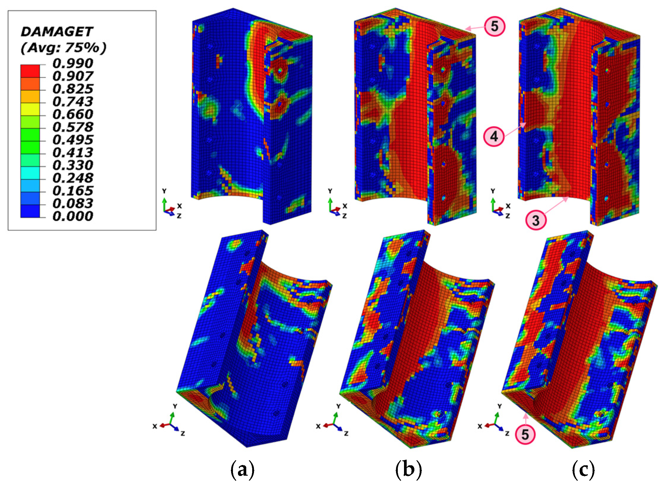
5.3. Analysis Results
6. Conclusions
- Under cyclic loading, the proposed joint achieved a plastic rotation of up to 0.05 rad and exhibited stable and full hysteresis loops. The joint provided sufficient flexural strength, stiffness, deformation capacity, and energy dissipation, meeting the seismic performance requirements for composite special moment-resisting frames as specified by ANSI/AISC 341 [35].
- Two consecutive pseudo-static tests demonstrated that the proposed joint could fully recover its initial strength and stiffness by replacing only the steel beam and endplate. Plastic deformation was primarily concentrated in the steel beam, while the deformation in the high-strength grout and square steel tube was negligible. The joint is therefore considered fully repairable.
- Although several through cracks developed in the high-strength grout under the ultimate bending moment at the beam end, and large areas deboned from the steel tube walls, the confinement provided by the steel tubes enabled the grout to continuously offer stable and reliable support to the beam endplate throughout the loading process.
- Weld failure was limited to the regions between the steel beam, endplate, and flange stiffeners. All other welds remained intact.
7. Future Work
Author Contributions
Funding
Data Availability Statement
Conflicts of Interest
References
- Han, L.H.; Li, W.; Bjorhovde, R. Developments and advanced applications of concrete-filled steel tubular (CFST) structures: Members. J. Constr. Steel Res. 2014, 100, 211–228. [Google Scholar] [CrossRef]
- Shams, M.; Saadeghvaziri, M.A. State of the art of concrete-filled steel tubular columns. Struct. J. 1997, 94, 558–571. [Google Scholar] [CrossRef]
- Aslani, F.; Uy, B.; Tao, Z.; Mashiri, F. Predicting the axial load capacity of high-strength concrete filled steel tubular columns. Steel Compos. Struct. 2015, 19, 967–993. [Google Scholar] [CrossRef]
- Inai, E.; Mukai, A.; Kai, M.; Tokinoya, H.; Fukumoto, T.; Mori, K. Behavior of concrete-filled steel tube beam columns. J. Struct. Eng. 2004, 130, 189–202. [Google Scholar] [CrossRef]
- Song, T.Y.; Han, L.H.; Yu, H.X. Concrete filled steel tube stub columns under combined temperature and loading. J. Constr. Steel Res. 2010, 66, 369–384. [Google Scholar] [CrossRef]
- Tao, Z.; Han, L.H.; Uy, B.; Chen, X. Post-fire bond between the steel tube and concrete in concrete-filled steel tubular columns. J. Constr. Steel Res. 2011, 67, 484–496. [Google Scholar] [CrossRef]
- Alostaz, Y.M.; Schneider, S.P. Analytical behavior of connections to concrete-filled steel tubes. J. Constr. Steel Res. 1996, 40, 95–127. [Google Scholar] [CrossRef]
- Azizinamini, A.; Schneider, S.P. Moment connections to circular concrete-filled steel tube columns. J. Struct. Eng. 2004, 130, 213–222. [Google Scholar] [CrossRef]
- Cheng, C.T.; Chung, L.L. Seismic performance of steel beams to concrete-filled steel tubular column connections. J. Constr. Steel Res. 2003, 59, 405–426. [Google Scholar] [CrossRef]
- Schneider, S.P.; Alostaz, Y.M. Experimental behavior of connections to concrete-filled steel tubes. J. Constr. Steel Res. 1998, 45, 321–352. [Google Scholar] [CrossRef]
- Ramirez Ortiz, C.; Areiza Palma, G.; Gutierrez Amador, A.D.; Ramirez Duque, J.L.; Cano Buitron, R.E.; Gonzales Escobar, L.F. Seismic behavior of a steel beam-to-concrete-filled steel tubular column connection using external diaphragms. Appl. Sci. 2022, 12, 3618. [Google Scholar] [CrossRef]
- Wang, J.F.; Han, L.H.; Uy, B. Behaviour of flush end plate joints to concrete-filled steel tubular columns. J. Constr. Steel Res. 2009, 65, 925–939. [Google Scholar] [CrossRef]
- Wang, J.F.; Chen, L.P. Experimental investigation of extended end plate joints to concrete-filled steel tubular columns. J. Constr. Steel Res. 2012, 79, 56–70. [Google Scholar] [CrossRef]
- Li, Y.L.; Chan, T.M.; Zhao, X.L. Review on blind bolted connections to concrete-filled steel tubes. Thin-Walled Struct. 2023, 183, 110444. [Google Scholar] [CrossRef]
- Wang, Z.B.; Tao, Z.; Li, D.S.; Han, L.H. Cyclic behaviour of novel blind bolted joints with different stiffening elements. Thin-Walled Struct. 2016, 101, 157–168. [Google Scholar] [CrossRef]
- Li, Y.L.; Zhao, X.L. Study on stainless steel blind bolted T-stub to concrete-filled stainless steel tube connections. Eng. Struct. 2022, 257, 114107. [Google Scholar] [CrossRef]
- Ng, W.H.; Kong, S.Y.; Chua, Y.S.; Bai, Y. Tensile behaviour of innovative one-sided bolts in concrete-filled steel tubular connections. J. Constr. Steel Res. 2022, 191, 107165. [Google Scholar] [CrossRef]
- Koloo, F.A.; Badakhshan, A.; Fallahnejad, H.; Jamkhaneh, M.E.; Ahmadi, M. Investigation of proposed concrete filled steel tube connections under reversed cyclic loading. Int. J. Steel Struct. 2018, 18, 163–177. [Google Scholar] [CrossRef]
- Elremaily, A.; Azizinamini, A. Design provisions for connections between steel beams and concrete filled tube columns. J. Constr. Steel Res. 2001, 57, 971–995. [Google Scholar] [CrossRef]
- Khanouki, M.A.; Sulong, N.R.; Shariati, M.; Tahir, M. Investigation of through beam connection to concrete filled circular steel tube (CFCST) column. J. Constr. Steel Res. 2016, 121, 144–162. [Google Scholar] [CrossRef]
- Beutel, J.; Thambiratnam, D.; Perera, N. Cyclic behaviour of concrete filled steel tubular column to steel beam connections. Eng. Struct. 2002, 24, 29–38. [Google Scholar] [CrossRef]
- Morino, S.; Tsuda, K. Design and construction of concrete-filled steel tube column system in Japan. Earthq. Eng. Eng. Seismol. 2003, 4, 51–73. [Google Scholar]
- DBJ 13-51; Technical Specification for Concrete-Filled Steel Tubular Structures. The Construction Department of Fujian Province: Fuzhou, China, 2003.
- Sheet, I.S.; Gunasekaran, U.; Macrae, G.A. Experimental investigation of CFT column to steel beam connections under cyclic loading. J. Constr. Steel Res. 2013, 86, 167–182. [Google Scholar] [CrossRef]
- Yao, H.; Goldsworthy, H.; Gad, E. Experimental and numerical investigation of the tensile behavior of blind-bolted T-stub connections to concrete-filled circular columns. J. Struct. Eng. 2008, 134, 198–208. [Google Scholar] [CrossRef]
- Tao, Z.; Li, W.; Shi, B.L.; Han, L.H. Behaviour of bolted end-plate connections to concrete-filled steel columns. J. Constr. Steel Res. 2017, 134, 194–208. [Google Scholar] [CrossRef]
- Li, X.; Xiao, Y.; Wu, Y.T. Seismic behavior of exterior connections with steel beams bolted to CFT columns. J. Constr. Steel Res. 2009, 65, 1438–1446. [Google Scholar] [CrossRef]
- ANSI/AISC 358; Prequalified Connections for Special and Intermediate Steel Moment Frames for Seismic Applications. American Institute of Steel Construction: Chicago, IL, USA, 2022.
- Miller, D.K. Lessons learned from the Northridge earthquake. Eng. Struct. 1998, 20, 249–260. [Google Scholar] [CrossRef]
- Bertero, V.V. Performance of Steel Building Structure During the Northridge Earthquake; UCB/EERC-94/09; Pacific Earthquake Engineering Research Center: Berkeley, CA, USA, 1994. [Google Scholar]
- Bertero, V.V. Seismological and Engineering Aspects of the January 17, 1995 Hyogoken-Nanbu (Kobe) Earthquake; UCB/EERC-95/10; Pacific Earthquake Engineering Research Center: Berkeley, CA, USA, 1995. [Google Scholar]
- GB 50017; Code for Design of Steel Structures. China Standard Press: Beijing, China, 2017.
- GB/T 1596; Code for Fly Ash Used for Cement and Concrete. China Standard Press: Beijing, China, 2005.
- GB/T 21236; Code for Silica Fume from Electric-Furnace. China Standard Press: Beijing, China, 2007.
- ANSI/AISC 341; Seismic Provisions for Structural Steel Buildings. American Institute of Steel Construction: Chicago, IL, USA, 2016.
- GB 50010; Code for Design of Concrete Structures. China Standard Press: Beijing, China, 2015.
- Wang, C.; Liu, J.; Lu, B.; Zhang, Y.; Ma, Z. Stiffness degradation and mechanical behavior of microfiber-modified high-toughness recycled aggregate concrete under constant load cycling. Eng. Fract. Mech. 2024, 312, 110608. [Google Scholar] [CrossRef]


| Item | Tag | Ø | |||||||
|---|---|---|---|---|---|---|---|---|---|
| Circular Tube | 406 | - | - | - | 10 | 273 | 355 | - | |
| Square Tube | - | 520 | 520 | 820 | 10 | 288 | 378 | - | |
| Beam Flange | - | - | 200 | - | 14 | 285 | 374 | - | |
| Beam Web | - | - | - | 450 | 9 | 293 | 391 | - | |
| Endplate | - | - | 240 | 770 | 30 | 250 | 362 | - | |
| Bolt | 30 | 600 | - | - | - | 940 | 1040 | - | |
| Beam Stiffener | - | 225 | - | 130 | 10 | 288 | 378 | - | |
| Cap Plate | - | 520 | 520 | - | 20 | 265 | 367 | - | |
| Tube Stiffener | - | - | 150 | 260 | 10 | 288 | 378 | - | |
| Core Concrete | C40 | 386 | - | - | - | - | - | - | 42.2 |
| Infilled Grout | C35 | - | 500 | 500 | 820 | - | - | - | 33.6 |
| Ingredient | Concrete | High-Strength Grout |
|---|---|---|
| Cement | 445 kg/m3 | 400 kg/m3 |
| Fly Ash | 55 kg/m3 | 65 kg/m3 |
| Silica Fume | - | 85 kg/m3 |
| Water | 175 kg/m3 | 120 kg/m3 |
| Superplasticizer | 1.4 L/m3 | 2 L/m3 |
| Fine Aggregate | 690 kg/m3 | 800 kg/m3 |
| Coarse Aggregate | 1035 kg/m3 | - |
| Item | Tag | Quantity | |||
|---|---|---|---|---|---|
| Tall Endplate | 1 | 615 | 440 | 30 | |
| Top Plate | 1 | 400 | 190 | 20 | |
| Bottom Plate | 1 | 400 | 150 | 20 | |
| Short Endplate | 1 | 400 | 400 | 20 | |
| Side Plate | 2 | 380 | 150 | 20 |
Disclaimer/Publisher’s Note: The statements, opinions and data contained in all publications are solely those of the individual author(s) and contributor(s) and not of MDPI and/or the editor(s). MDPI and/or the editor(s) disclaim responsibility for any injury to people or property resulting from any ideas, methods, instructions or products referred to in the content. |
© 2025 by the authors. Licensee MDPI, Basel, Switzerland. This article is an open access article distributed under the terms and conditions of the Creative Commons Attribution (CC BY) license (https://creativecommons.org/licenses/by/4.0/).
Share and Cite
Gao, Y.; Zhu, P.; Liu, J.; Lou, F. Seismic Behavior and Resilience of an Endplate Rigid Connection for Circular Concrete-Filled Steel Tube Columns. Buildings 2025, 15, 2035. https://doi.org/10.3390/buildings15122035
Gao Y, Zhu P, Liu J, Lou F. Seismic Behavior and Resilience of an Endplate Rigid Connection for Circular Concrete-Filled Steel Tube Columns. Buildings. 2025; 15(12):2035. https://doi.org/10.3390/buildings15122035
Chicago/Turabian StyleGao, Yu, Peilin Zhu, Junping Liu, and Feng Lou. 2025. "Seismic Behavior and Resilience of an Endplate Rigid Connection for Circular Concrete-Filled Steel Tube Columns" Buildings 15, no. 12: 2035. https://doi.org/10.3390/buildings15122035
APA StyleGao, Y., Zhu, P., Liu, J., & Lou, F. (2025). Seismic Behavior and Resilience of an Endplate Rigid Connection for Circular Concrete-Filled Steel Tube Columns. Buildings, 15(12), 2035. https://doi.org/10.3390/buildings15122035