
Experimental Study on the Eccentric Compression Behavior of Stiffened Alkali-Activated Concrete-Filled Steel Tube Short Columns

Abstract
1. Introduction
2. Experimental Scheme
2.1. Specimen Design
2.2. Test Materials
2.2.1. Steel Tubes and Stiffeners
2.2.2. Core Concrete
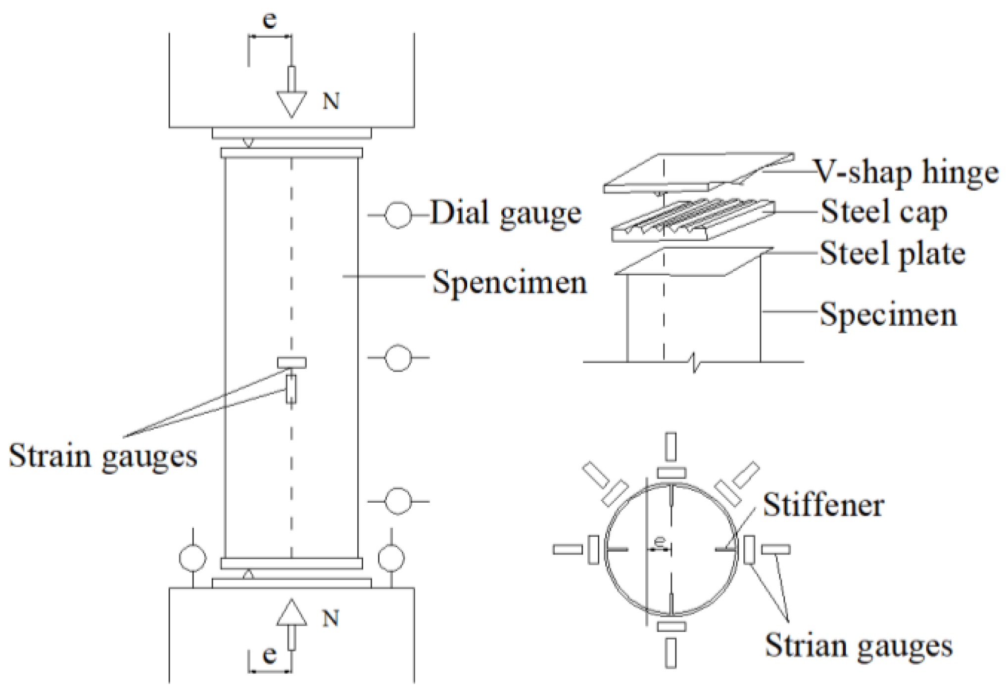
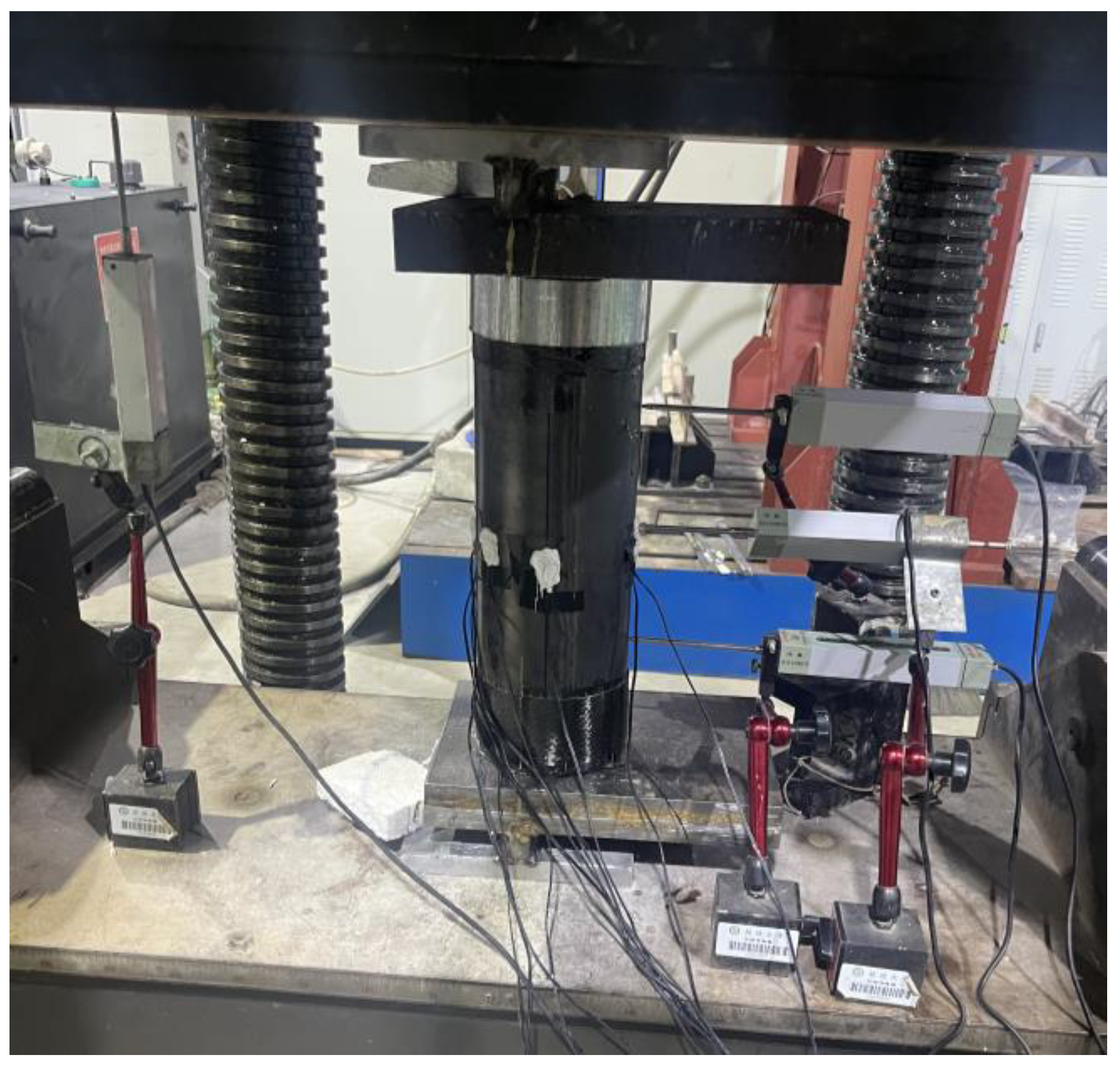
2.3. Testing Equipment and Methods
3. Results Analysis
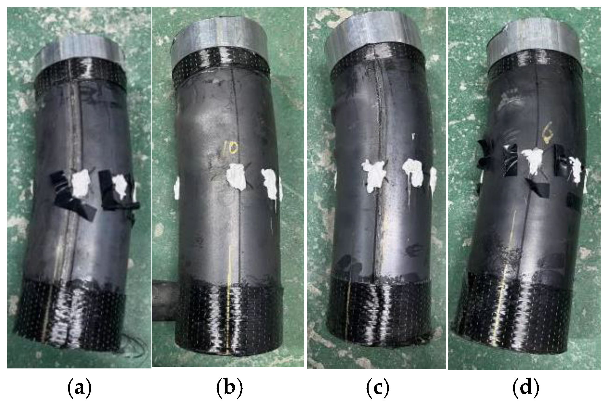
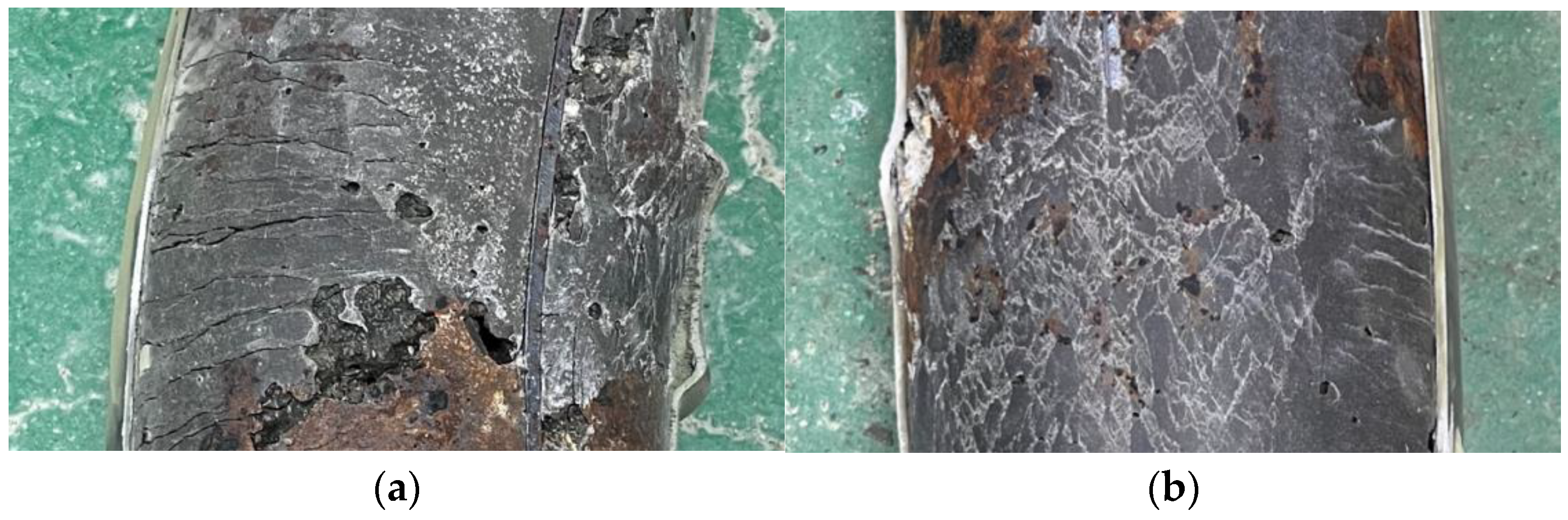
3.1. Failure Modes
3.2. Eccentric Compression Bearing Capacity
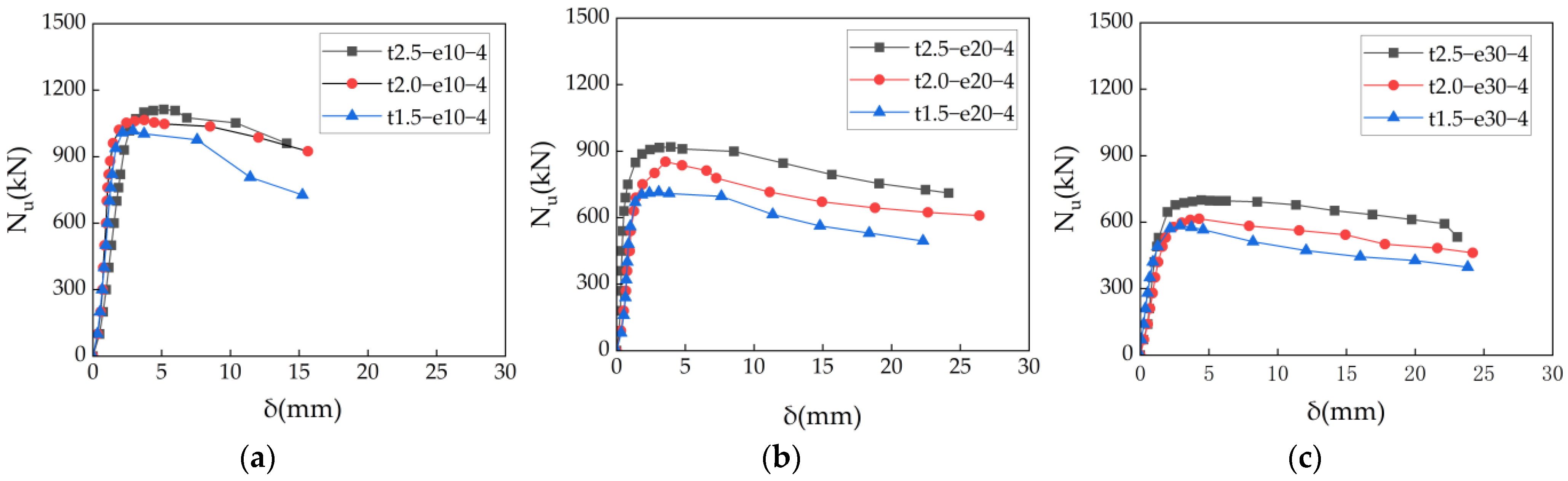
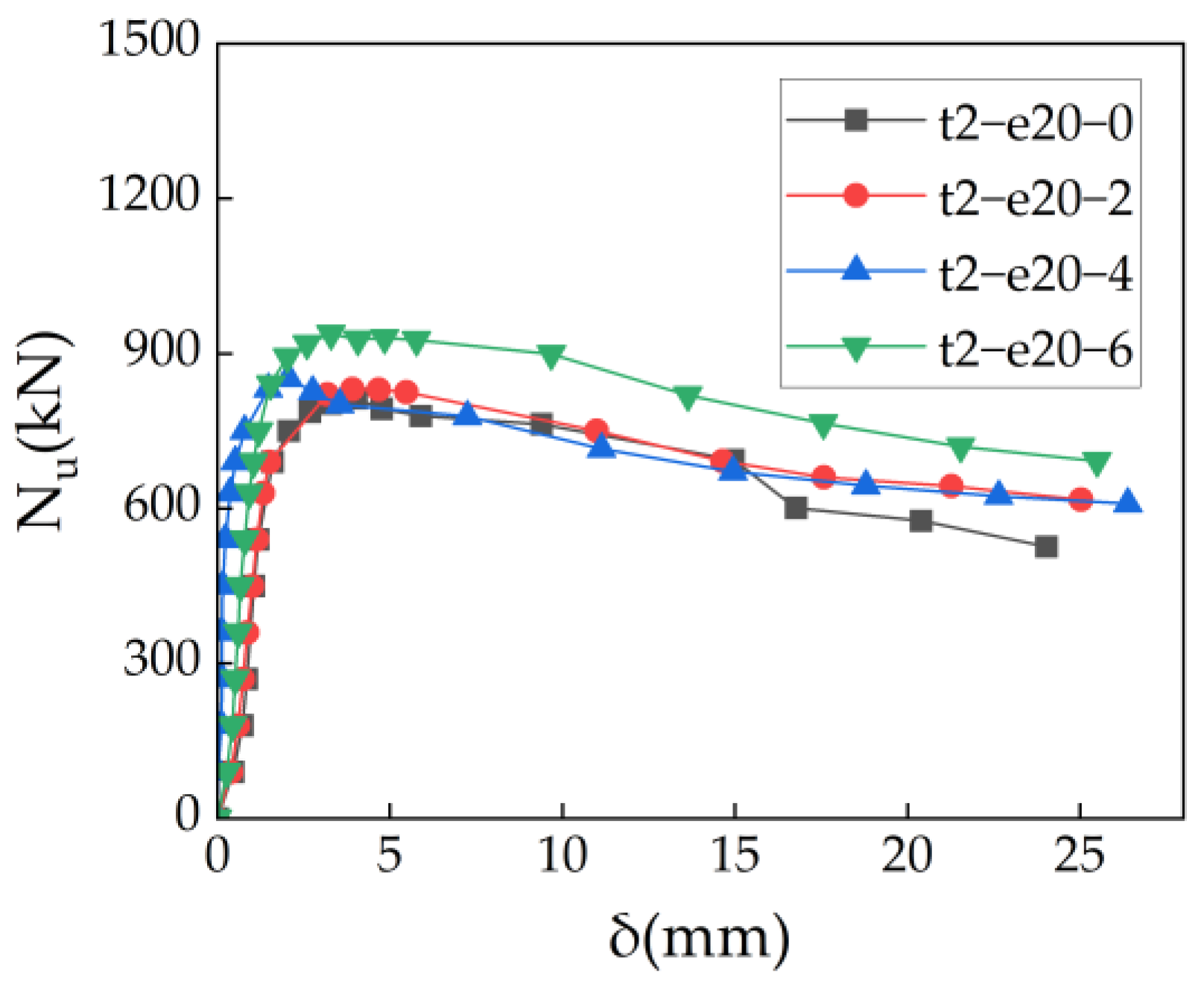
3.3. Lateral Mid-Span Deflection Curves
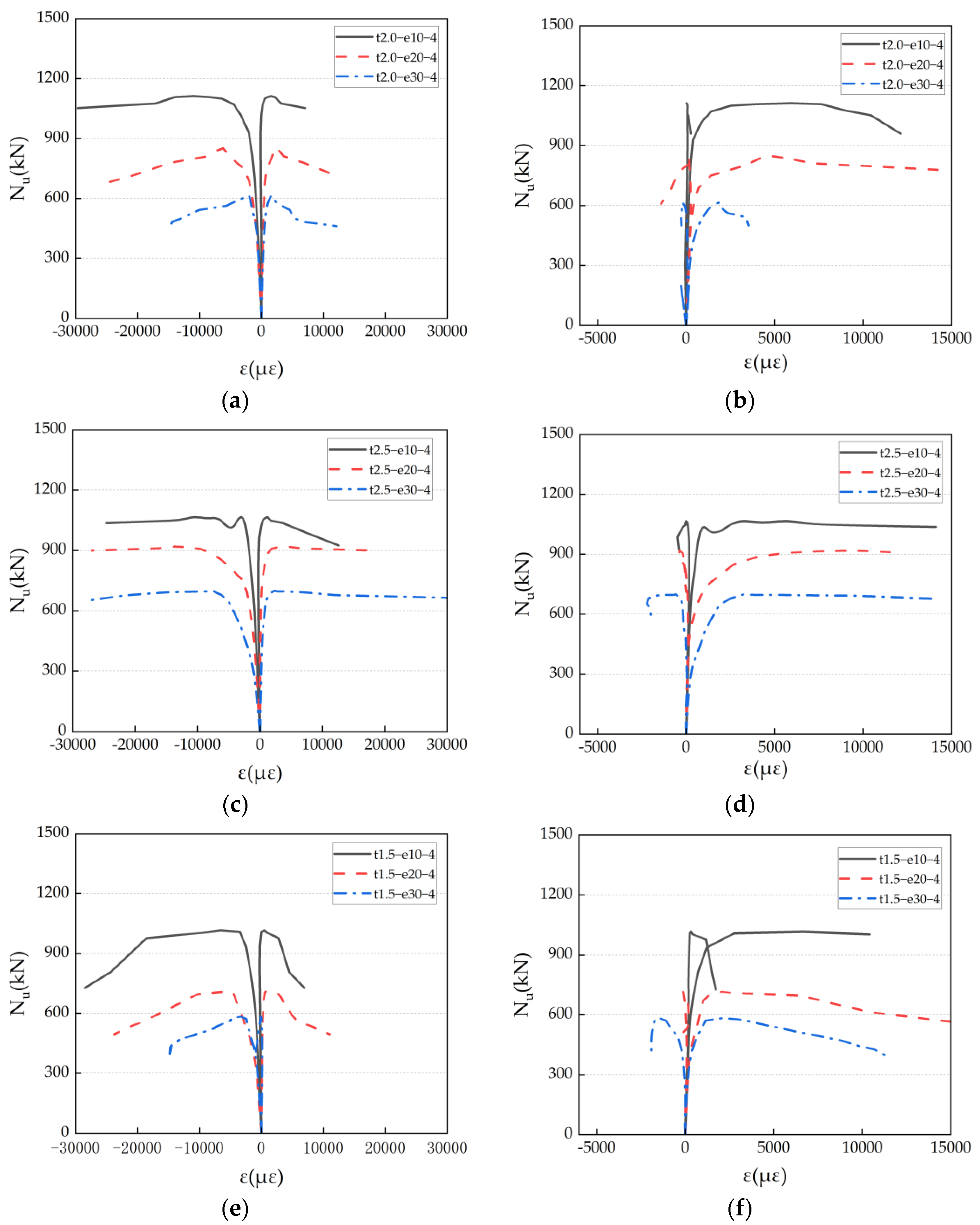
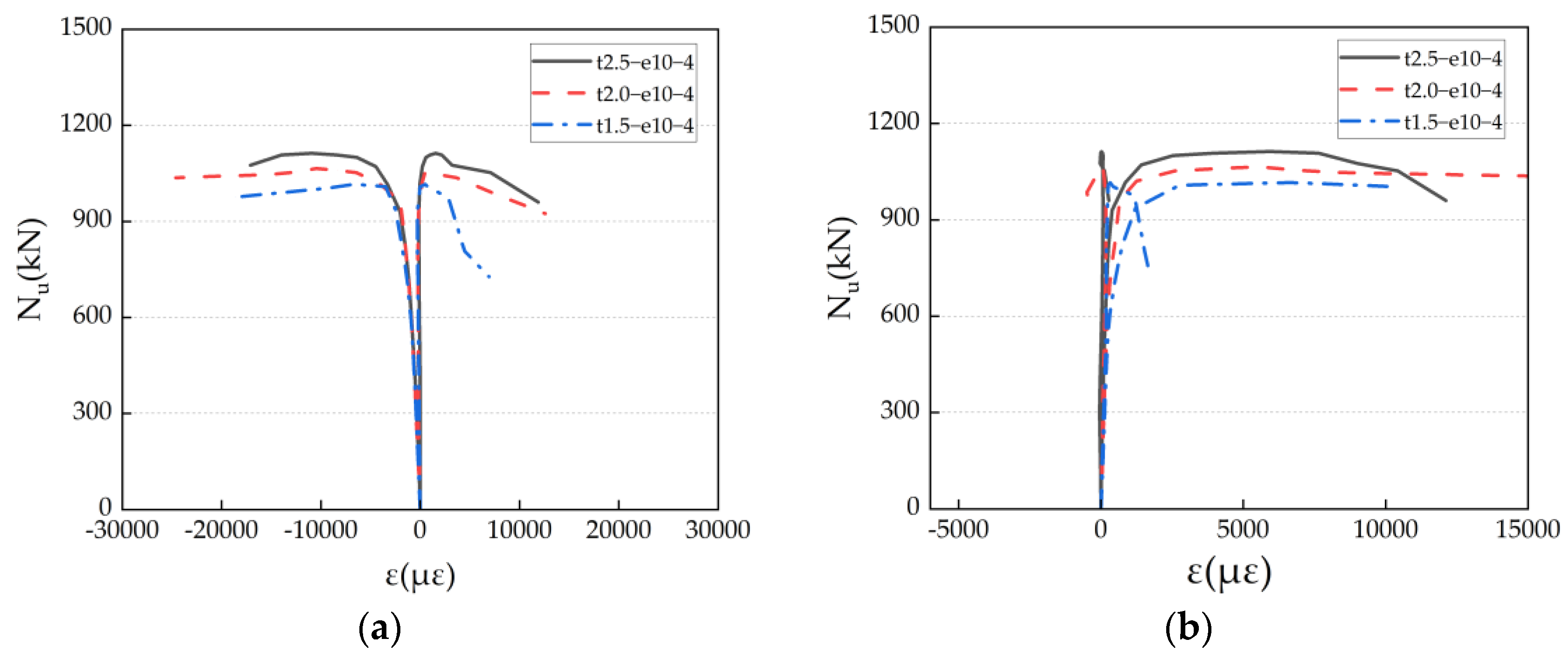
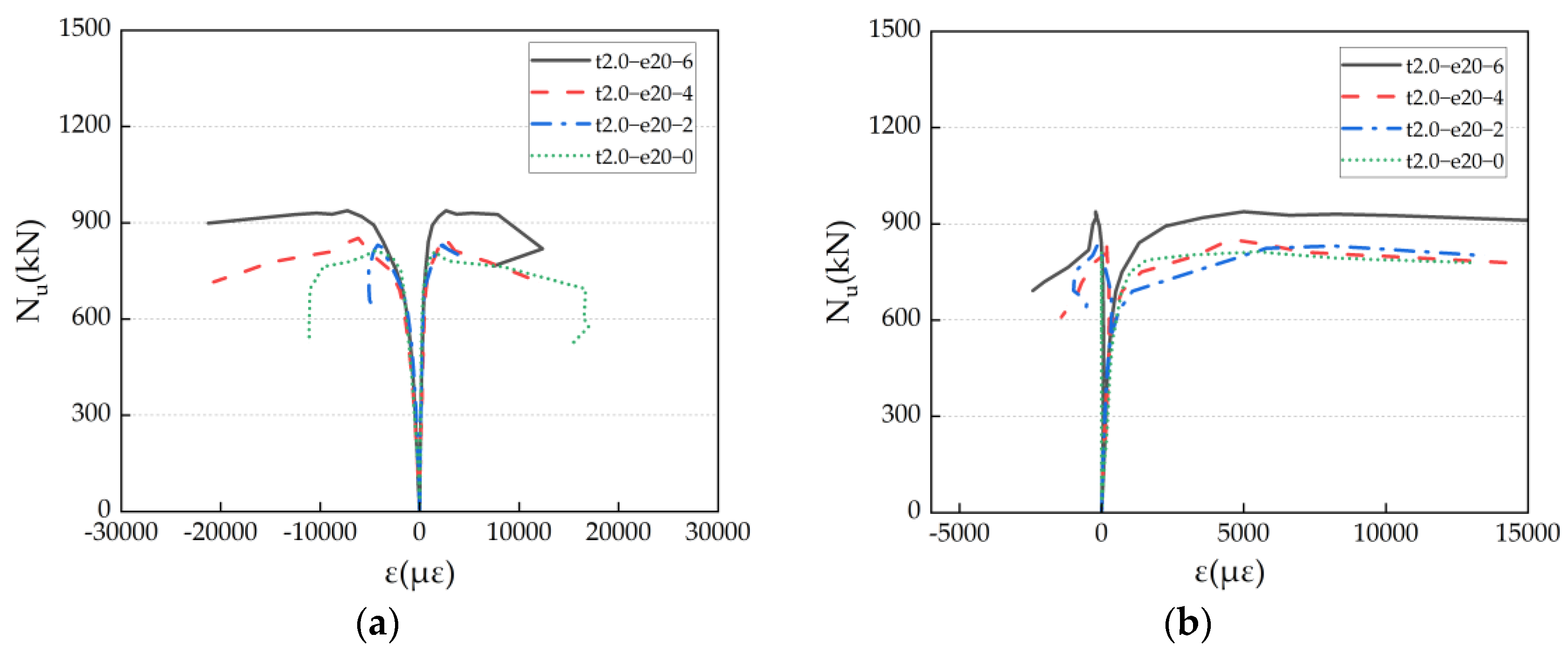
3.4. Stress–Strain Curves
4. Bearing Capacity Prediction of ACFST

| Specification | Formula | ID |
|---|---|---|
| GB 50936-2014 | (1) | |
| Composite Structures Design Specification | (2) | |
| AISC-LRFD Specification | (3) | |
5. Prediction Model for ACFST Short Columns Under Eccentric Loading
5.1. Axial Compression Bearing Capacity of ACFST
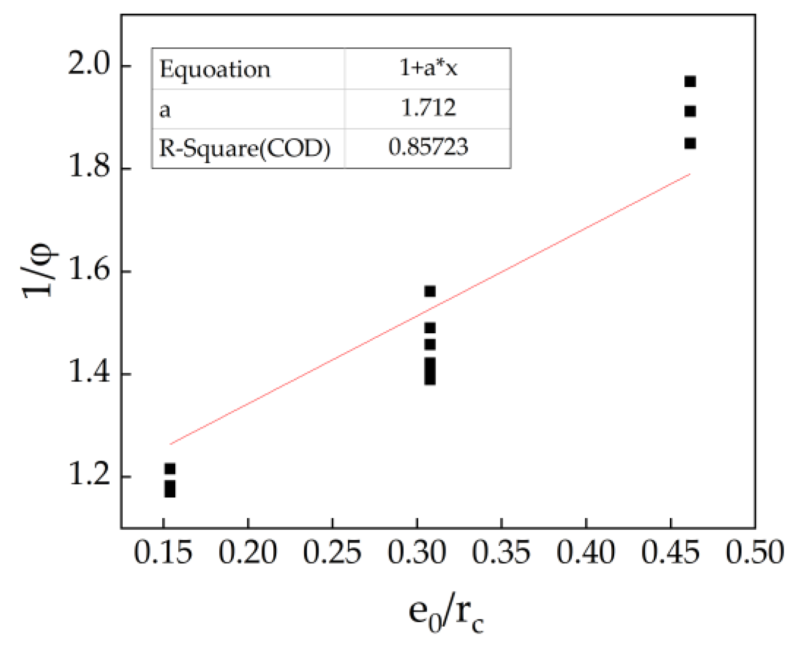
5.2. Capacity Reduction Factor Considering the Impact of Eccentricity
6. Conclusions
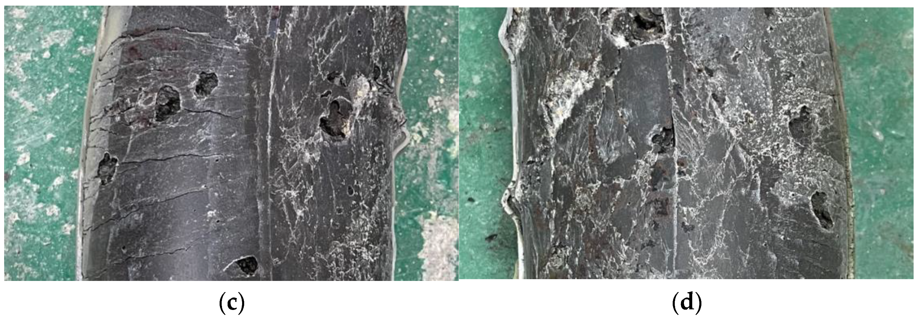
- In this experiment, the failure process of ACFST under eccentric compression load was generally consistent. All specimens exhibited bending-dominated failure. With increasing eccentric compression, the circular steel tubes reached yield strength and subsequently crushed the internal alkali-activated concrete due to excessive strain, leading to failure.
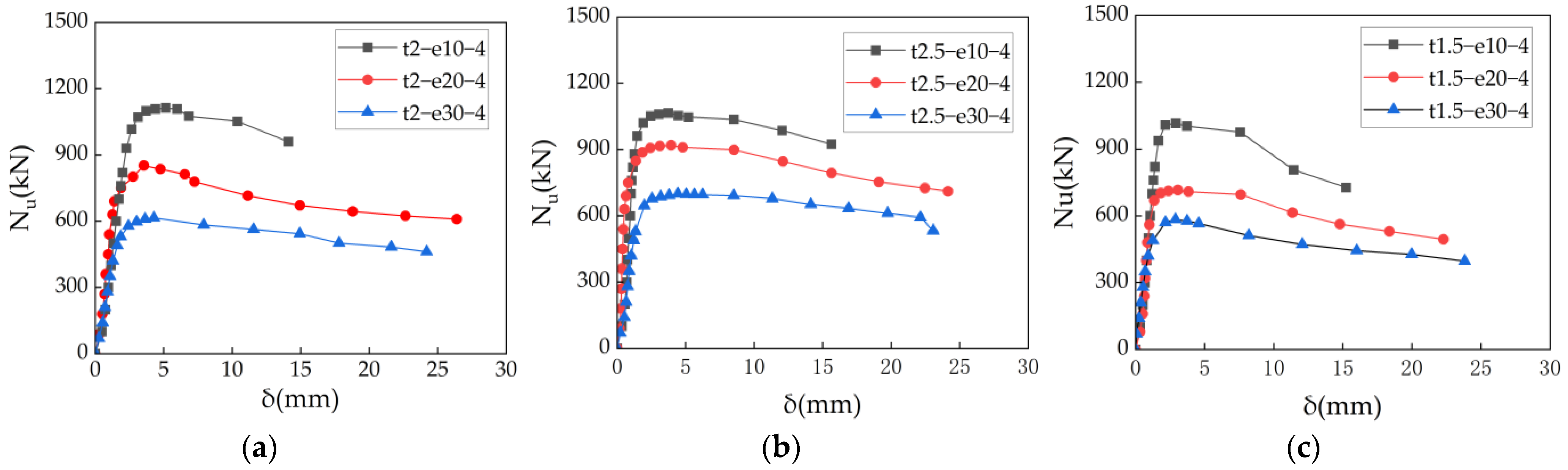
- The load–axial displacement and load–lateral deflection curves of ACFST under eccentric compression consist of an initial linear stage, a nonlinear stage before peak load, and a descending stage after peak load. When other parameters remain constant, higher eccentricity ratios and larger columns generally have lower ultimate bearing capacities. Stiffening ribs delay local buckling onset and suppress stress concentrations, demonstrating higher bearing capacity.
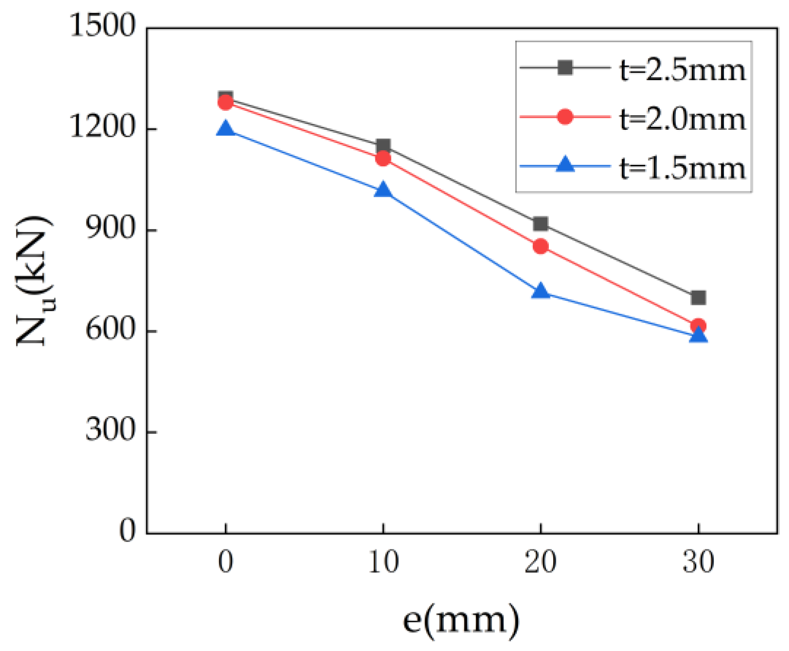
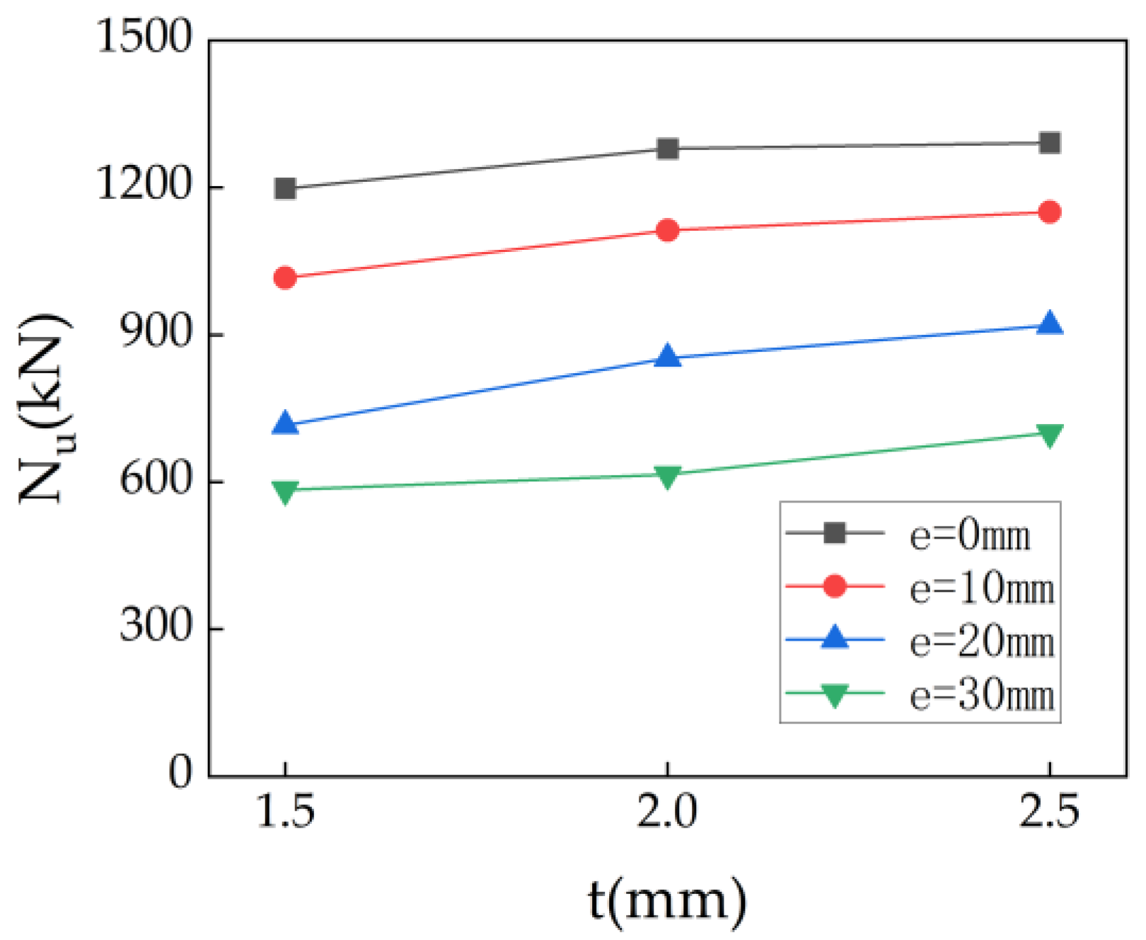
- The ultimate bearing capacity of the specimens increased with the increase in the steel ratio, but decreased as the load eccentricity ratio increased. Based on the experimental results and current standards, a calculation formula for the eccentric compression bearing capacity of ACFST has been proposed. The calculation results are in good agreement with the experimental results, indicating that the calculation formula proposed in this paper can accurately predict the ultimate bearing capacity of ACFST under eccentric load.
Author Contributions
Funding
Data Availability Statement
Conflicts of Interest
Abbreviations
| ACFST | alkali-activated concrete-filled steel tube |
| FA | fly ash |
| FS | furnace Slag |
| CoV | coefficient of variation |
References
- Wang, J.; Han, J.; Zhu, C.; Lu, W.; Zhang, Y.; He, X.; Liu, K.; Chen, Y. Structural optimization and engineering application of concrete-filled steel tubular composite supports. Eng. Fail. Anal. 2024, 159, 108082. [Google Scholar]
- Lan, X.; Wang, Y.; Tan, B.; Zhang, Y. An assessment of application of the component-based method to full range behaviour of joints between steel beam to concrete filled steel tube columns under extreme loading conditions. Eng. Struct. 2024, 309, 118057. [Google Scholar]
- Deng, Y.Q.; Huang, Y.; Young, B. Design of concrete-filled high-strength steel RHS and SHS tubes under bending. Eng. Struct. 2024, 320, 118891. [Google Scholar]
- Ma, H.; Chen, Y.; Bai, H.; Zhao, Y. Eccentric compression performance of composite columns composed of RAC-filled circular steel tube and profile steel. Eng. Struct. 2019, 201, 109778. [Google Scholar]
- Wang, J.; Chen, J.; Liu, M. Theoretical model for CFRP-confined spontaneous combustion gangue coarse aggregate concrete-filled steel tube stub columns under axial compression. Constr. Build. Mater. 2024, 415, 135113. [Google Scholar]
- Tam, V.W.Y.; Tao, Z.; Evangelista, A. Performance of recycled aggregate concrete filled steel tubular (RACFST) stub columns with expansive agent. Constr. Build. Mater. 2021, 272, 121627. [Google Scholar]
- Hu, H.S.; Xu, L.; Guo, Z.X.; Shahrooz, B.M. Behavior of eccentrically loaded square spiral-confined high-strength concrete-filled steel tube columns. Eng. Struct. 2020, 216, 110743. [Google Scholar]
- Li, L.; Lai, Z.; Chen, B. Ultra-high strength concrete filled steel tube members: Classification, experimental database, and design. Eng. Struct. 2024, 300, 117210. [Google Scholar]
- Zong, S.; Lu, Y.; Ma, W.; Liu, Z.; Li, P. Research on eccentric-compressive behaviour of steel-fiber-reinforced recycled concrete-filled square steel tube short columns. J. Constr. Steel Res. 2023, 206, 107910. [Google Scholar]
- Tao, Z.; Cao, Y.F.; Pan, Z.; Hassan, M.K. Compressive behaviour of geopolymer concrete-filled steel columns at ambient and elevated temperatures. Int. J. High-Rise Build. 2018, 7, 327–342. [Google Scholar]
- Zhang, Z.; Guo, X.; Song, Y.; Sun, Q.; Tian, P.; Hu, G. Numerical investigation and design of CFST columns strengthened by CFRP grid-reinforced ECC under eccentric compression. Eng. Struct. 2024, 301, 117253. [Google Scholar]
- Diao, Y.; Wang, Y.; He, H.; Zou, Y.; Hassanein, M. On the behaviour of diagonally-stiffened concrete-filled steel tube-to-SHS steel brace T-joints: An experimental and numerical investigation. J. Constr. Steel Res. 2025, 225, 109176. [Google Scholar]
- Zhou, Z.; Denavit, M.D.; Zhou, X. New cross-sectional slenderness limits for stiffened rectangular concrete-filled steel tubes. Eng. Struct. 2023, 280, 115689. [Google Scholar]
- Luo, K.R.; Shu, G.P.; Qin, Y.; Yu, L.; Li, B.H.; Liu, W.R. Flexural behavior of circular concrete-filled steel tube members reinforced with annular stiffener. J. Constr. Steel Res. 2025, 224, 109094. [Google Scholar]
- Arokiaprakash, A.; Selvan, S.S.; Anandh, K.S.; Adamu, M. Advancements in light-gauge steel rectangular CFST columns: A comprehensive experimental study. Structures 2024, 68, 107231. [Google Scholar]
- Xu, K.; Wang, W.; Zhang, L.; Meng, X.; Yang, C. Study on the mechanical behavior of inequiaxial and stiffened L-shaped concrete-filled steel tube short columns under uniaxial compression. Structures 2024, 70, 107626. [Google Scholar]
- Li, B.; Yang, Y.; Liu, J.; Cheng, Y.; Chen, Y.F. Effect of vertical stiffeners on the seismic performance of T-shaped CFST column to steel beam joint. Struct. Des. Tall Spec. Build. 2024, 33, e2131. [Google Scholar]
- Shen, L.; Yang, B.; Ding, M.; Feng, C.; Wang, D.; Liu, M.; Elchalakani, M. Experimental and numerical studies on the axial compression performance of hexagonal stiffened CFDST stub columns. Compos. Struct. 2023, 311, 116801. [Google Scholar]
- Zheng, M.; Nie, X.; Ding, R. Experimental and numerical research on the uniaxial behavior of the stiffened circular concrete-filled steel tube stub columns. Eng. Struct. 2024, 306, 117785. [Google Scholar]
- Hassanein, M.; Huang, W.-F.; Shao, Y.-B.; Cashell, K.; Elsisy, A. Confinement-based design and behaviour of concrete-filled stiffened steel tubular square slender columns. Ocean Eng. 2024, 304, 117845. [Google Scholar]
- Zheng, Y.; Lin, Y.; Liang, W. Concentric and eccentric compressive behaviors of stiffened T-shaped CFST columns. J. Constr. Steel Res. 2024, 212, 108229. [Google Scholar]
- Singh, H.; Tiwary, A.K. Experimental and numerical investigation on concrete filled steel tube columns reinforced with diagonal stiffeners under axial loading. Eng. Struct. 2023, 292, 116602. [Google Scholar]
- Dai, P.; Yang, L.; Yun, X.; Wang, F.; Zhang, L. Experimental study of concrete-filled stainless steel tubular stub columns with circular and square cross-sections subjected to combined compression and bending. Eng. Struct. 2024, 305, 117773. [Google Scholar]
- Kumar, S.; Gupta, P.K.; Iqbal, M.A. Experimental and numerical study on self-compacting alkali-activated slag concrete-filled steel tubes. J. Constr. Steel Res. 2024, 214, 108453. [Google Scholar]
- Zhu, J.Y.; Chan, T.M. Experimental investigation on steel-tube-confined-concrete stub column with different cross-section shapes under uniaxial-compression. J. Constr. Steel Res. 2019, 162, 105729. [Google Scholar] [CrossRef]
- Song, C.; Wang, Y.B.; Li, G.Q. Interaction and compatibility between steel and concrete of circular CFST stub columns with high-strength materials. J. Constr. Steel Res. 2024, 221, 108873. [Google Scholar]
- Yan, X.F.; Lin, S.; Zhao, Y.G. Behaviour and confinement mechanism of circular concrete-filled aluminum alloy tubular stub columns under axial compression. Mar. Struct. 2024, 95, 103600. [Google Scholar]
- Ma, K.; Zhou, Q.; Li, L.; Wang, C. Experimental study on concrete-filled stainless steel tubular stub columns under axial compression load. Structures 2024, 63, 106436. [Google Scholar]
- Yan, X.F.; He, M.N.; Hao, J.P.; Lin, S. Theoretical model of circular concrete-filled aluminum alloy tubular short columns under axial compression. Eng. Struct. 2024, 303, 117549. [Google Scholar]
- Corinaldesi, V.; Gnappi, G.; Moriconi, G.; Montenero, A. Reuse of ground waste glass as aggregate for mortars. Waste Manag. 2005, 25, 197–201. [Google Scholar]
- Etxeberria, M.; Vázquez, E.; Mari, A.; Barra, M. Influence of amount of recycled coarse aggregates and production process on properties of recycled aggregate concrete. Cem. Concr. Res. 2007, 37, 735–742. [Google Scholar]
- Hossain, M.U.; Poon, C.S.; Wong, M.Y.K.; Khine, A. Techno-environmental feasibility of wood waste derived fuel for cement production. J. Clean. Prod. 2019, 230, 663–671. [Google Scholar]
- Thilakarathna, P.S.M.; Seo, S.; Baduge, K.K.; Lee, H.; Mendis, P.; Foliente, G. Embodied carbon analysis and benchmarking emissions of high and ultra-high strength concrete using machine learning algorithms. J. Clean. Prod. 2020, 262, 121281. [Google Scholar]
- Yang, K.H.; Song, J.K.; Song, K.I. Assessment of CO2 reduction of alkali-activated concrete. J. Clean. Prod. 2013, 39, 265–272. [Google Scholar]
- Ma, C.K.; Awang, A.Z.; Omar, W. Structural and material performance of geopolymer concrete: A review. Constr. Build. Mater. 2018, 186, 90–102. [Google Scholar]
- Ding, Y.; Dai, J.-G.; Shi, C.-J. Mechanical properties of alkali-activated concrete: A state-of-the-art review. Constr. Build. Mater. 2016, 127, 17–38. [Google Scholar]
- Alsalman, A.; Assi, L.N.; Kareem, R.S.; Carter, K.; Ziehl, P. Energy and CO2 emission assessments of alkali-activated concrete and Ordinary Portland Cement concrete: A comparative analysis of different grades of concrete. Clean. Environ. Syst. 2021, 3, 100047. [Google Scholar]
- Li, B.; Wu, F.; Xia, D.; Li, Y.; Cui, K.; Wu, F.; Yu, J. Compressive and flexural behavior of alkali-activated slag-based concrete: Effect of recycled aggregate content. J. Build. Eng. 2023, 67, 105993. [Google Scholar]
- Abdel-Gawwad, H.A.; Mohammed, M.S.; Alomayri, T. Single and dual effects of magnesia and alumina nano-particles on strength and drying shrinkage of alkali activated slag. Constr. Build. Mater. 2019, 228, 116827. [Google Scholar]
- Hanjitsuwan, S.; Injorhor, B.; Phoo-Ngernkham, T.; Damrongwiriyanupap, N.; Li, L.-Y.; Sukontasukkul, P.; Chindaprasirt, P. Drying shrinkage, strength and microstructure of alkali-activated high-calcium fly ash using FGD-gypsum and dolomite as expansive additive. Cem. Concr. Compos. 2020, 114, 103760. [Google Scholar]
- Huang, D.; Chen, P.; Peng, H.; Yang, Y.; Yuan, Q.; Su, M. A review and comparison study on drying shrinkage prediction between alkali-activated fly ash/slag and ordinary Portland cement. Constr. Build. Mater. 2021, 305, 124760. [Google Scholar]
- Zhou, X.; Hou, D.; Chen, T.; Wang, X. The development of concrete filled steel tube with enhanced performance via the use of expansive ultra high performance concrete. J. Build. Eng. 2023, 79, 107793. [Google Scholar]
- Zeng, J.-J.; Xiang, H.-Y.; Cai, W.-J.; Zhou, J.-K.; Zhuge, Y. Behavior of large-scale FRP-confined square RC columns with UHP-ECC section curvilinearization under eccentric compression. Eng. Struct. 2024, 301, 117288. [Google Scholar]
- Ye, H.; Radlińska, A.; Shi, C. Shrinkage mitigation strategies of alkali-activated materials: A review. Cem. Concr. Compos. 2021, 121, 104062.3. [Google Scholar]
- Shen, P.; Lu, J.-X.; Zheng, H.; Lu, L.; Wang, F.; He, Y.; Hu, S. Expansive ultra-high performance concrete for concrete-filled steel tube applications. Cem. Concr. Compos. 2020, 114, 103813. [Google Scholar]
- GB 50936-2014; Technical Code for Concrete Filled Steel Tubular Structures. Ministry of Housing and Urban-Rural Development of the People’s Republic of China: Beijing, China, 2014. (In Chinese)
- Shen, S.L.; Xu, L.H. Design of Steel and Composite Structures, 2nd ed.; China Architecture & Building Press: Beijing, China, 2011; pp. 1–420. (In Chinese) [Google Scholar]
- American Institute of Steel Construction. Load and Resistance Factor Design Specification for Structural Steel Buildings; AISC: Chicago, IL, USA, 2016. [Google Scholar]
- GB/T 228.1-2010; Metallic Materials: Tensile Tests—Part 1: Test Method at Room Temperature. Standards Press of China: Beijing, China, 2010. (In Chinese)
- Liu, Y.; Yang, X.; Tian, W.; Fu, Z.; Zhao, Y.; Li, B.; Li, S.; Xu, D.; Yu, S.; Yao, Z.; et al. Mechanical Properties and Microstructure of Alkali-Activated Cements with Granulated Blast Furnace Slag, Fly Ash and Desert Sand. Buildings 2024, 14, 3422. [Google Scholar] [CrossRef]
- Mander, J.A.B.; Priestley, M.J.N. Theoretical Stress-Strain Model for Confined Concrete. J. Struct. Eng. 1988, 114, 1804–1826. [Google Scholar] [CrossRef]
- Wang, Z.; Qiao, Q.; Cao, W.; Gao, X. Axial compressive behavior of square steel tube confined rubberized concrete stub columns. J. Build. Eng. 2022, 52, 104371. [Google Scholar] [CrossRef]


| Number | Specimen | D × L/mm | t/mm | hs × ts | e/mm | Nu |
|---|---|---|---|---|---|---|
| 1 | t2-e20-0 | 133 × 400 | 2 | - | 20 | 813 |
| 2 | t2-e20-2 | 133 × 400 | 2 | 20 × 2 | 20 | 831 |
| 3 | t2-e20-4 | 133 × 400 | 2 | 20 × 4 | 20 | 852 |
| 4 | t2-e20-6 | 133 × 400 | 2 | 20 × 6 | 20 | 872 |
| 5 | t2-e10-4 | 133 × 400 | 2 | 20 × 4 | 10 | 1035 |
| 6 | t2-e30-4 | 133 × 400 | 2 | 20 × 4 | 30 | 632 |
| 7 | t2-e0-4 | 133 × 400 | 2 | 20 × 4 | 0 | 1279 |
| 8 | t2.5-e10-4 | 133 × 400 | 2.5 | 20 × 4 | 10 | 1065 |
| 9 | t2.5-e20-4 | 133 × 400 | 2.5 | 20 × 4 | 20 | 919 |
| 10 | t2.5-e30-4 | 133 × 400 | 2.5 | 20 × 4 | 30 | 700 |
| 11 | t2.5-0-4 | 133 × 400 | 2.5 | 20 × 4 | 0 | 1291 |
| 12 | t1.5-e10-4 | 133 × 400 | 1.5 | 20 × 4 | 10 | 944 |
| 13 | t1.5-e20-4 | 133 × 400 | 1.5 | 20 × 4 | 20 | 715 |
| 14 | t1.5-e30-4 | 133 × 400 | 1.5 | 20 × 4 | 30 | 584 |
| 15 | t1.5-e0-4 | 133 × 400 | 1.5 | 20 × 4 | 0 | 1198 |
| Mixture Proportions (kg/m3) | Mechanical Proportions (Mpa) | |||||||||
|---|---|---|---|---|---|---|---|---|---|---|
| FA | FS | Water | Superplasticizer | Aggregates | sand | Expansion Agent | NaOH | Na2O·nSiO2 | ||
| 160 | 240 | 180 | 4 | 983 | 628 | 8 | 17.7 | 44.1 | 75 | 60 |
| Specimen | |||||||
|---|---|---|---|---|---|---|---|
| t2-e20-0 | 813 | 480.6 | 0.59 | 652.7 | 0.80 | 319.4 | 0.39 |
| t2-e20-2 | 831 | 505.9 | 0.61 | 680.6 | 0.82 | 376.6 | 0.45 |
| t2-e20-4 | 852 | 530.9 | 0.62 | 708.5 | 0.83 | 429.1 | 0.50 |
| t2-e20-6 | 872 | 568.8 | 0.65 | 736.5 | 0.84 | 457.7 | 0.52 |
| t2-e10-4 | 1035 | 678.2 | 0.66 | 862.7 | 0.83 | 614.2 | 0.59 |
| t2-e30-4 | 615 | 440.4 | 0.72 | 601 | 0.98 | 329.8 | 0.54 |
| t2-e0-4 | 1279 | 1004.2 | 0.79 | 1102 | 0.86 | 1079.6 | 0.84 |
| t2.5-e10-4 | 1065 | 715.8 | 0.67 | 940.8 | 0.88 | 673.1 | 0.63 |
| t2.5-e20-4 | 919 | 560.5 | 0.61 | 772.6 | 0.84 | 478.1 | 0.52 |
| t2.5-e30-4 | 700 | 465.2 | 0.66 | 655.5 | 0.94 | 370.8 | 0.53 |
| t2.5-0-4 | 1291 | 1065.8 | 0.83 | 1202 | 0.93 | 1136.2 | 0.88 |
| t1.5-e10-4 | 944 | 638.9 | 0.68 | 780.6 | 0.83 | 551.1 | 0.58 |
| t1.5-e20-4 | 715 | 500 | 0.70 | 641 | 0.90 | 377.1 | 0.53 |
| t1.5-e30-4 | 584 | 414.5 | 0.71 | 543 | 0.93 | 286.6 | 0.49 |
| t1.5-e0-4 | 1198 | 940.8 | 0.79 | 997 | 0.83 | 1023 | 0.85 |
| Mean | 0.68 | 0.86 | 0.59 | ||||
| CoV | 0.40085 | 0.23886 | 0.94839 |
| Specimens | Error % | ||||
|---|---|---|---|---|---|
| t2-e20-0 | 0.307 | 813 | 742 | 0.91 | 8.73 |
| t2-e20-2 | 0.307 | 831 | 765 | 0.92 | 7.94 |
| t2-e20-4 | 0.307 | 852 | 793 | 0.93 | 6.92 |
| t2-e20-6 | 0.307 | 872 | 821 | 0.94 | 5.85 |
| t2-e10-4 | 0.153 | 1035 | 959 | 0.93 | 7.34 |
| t2-e30-4 | 0.461 | 632 | 677 | 1.07 | 7.12 |
| t2-e0-4 | - | 1279 | 1211 | 0.95 | 5.32 |
| t2.5-e10-4 | 0.153 | 1065 | 1024 | 0.96 | 3.85 |
| t2.5-e20-4 | 0.307 | 919 | 848 | 0.92 | 7.73 |
| t2.5-e30-4 | 0.461 | 700 | 723 | 1.03 | 3.29 |
| t2.5-0-4 | - | 1291 | 1294 | 1.00 | 0.23 |
| t1.5-e10-4 | 0.153 | 944 | 883 | 0.94 | 6.46 |
| t1.5-e20-4 | 0.307 | 715 | 731 | 1.02 | 2.24 |
| t1.5-e30-4 | 0.461 | 584 | 623 | 1.07 | 6.68 |
| t1.5-e0-4 | - | 1198 | 1116 | 0.93 | 6.84 |
Disclaimer/Publisher’s Note: The statements, opinions and data contained in all publications are solely those of the individual author(s) and contributor(s) and not of MDPI and/or the editor(s). MDPI and/or the editor(s) disclaim responsibility for any injury to people or property resulting from any ideas, methods, instructions or products referred to in the content. |
© 2025 by the authors. Licensee MDPI, Basel, Switzerland. This article is an open access article distributed under the terms and conditions of the Creative Commons Attribution (CC BY) license (https://creativecommons.org/licenses/by/4.0/).
Share and Cite
Wang, H.; Peng, Z.; Wang, T.; Pei, C. Experimental Study on the Eccentric Compression Behavior of Stiffened Alkali-Activated Concrete-Filled Steel Tube Short Columns. Buildings 2025, 15, 2457. https://doi.org/10.3390/buildings15142457
Wang H, Peng Z, Wang T, Pei C. Experimental Study on the Eccentric Compression Behavior of Stiffened Alkali-Activated Concrete-Filled Steel Tube Short Columns. Buildings. 2025; 15(14):2457. https://doi.org/10.3390/buildings15142457
Chicago/Turabian StyleWang, Hongjie, Zhixin Peng, Tianqi Wang, and Changchun Pei. 2025. "Experimental Study on the Eccentric Compression Behavior of Stiffened Alkali-Activated Concrete-Filled Steel Tube Short Columns" Buildings 15, no. 14: 2457. https://doi.org/10.3390/buildings15142457
APA StyleWang, H., Peng, Z., Wang, T., & Pei, C. (2025). Experimental Study on the Eccentric Compression Behavior of Stiffened Alkali-Activated Concrete-Filled Steel Tube Short Columns. Buildings, 15(14), 2457. https://doi.org/10.3390/buildings15142457