
Experimental and Mechanism Study on Axial Compressive Performance of Double Steel Tube Columns Filled with Recycled Concrete Containing Abandoned Brick Aggregate


Abstract
1. Introduction
2. Experimental Program
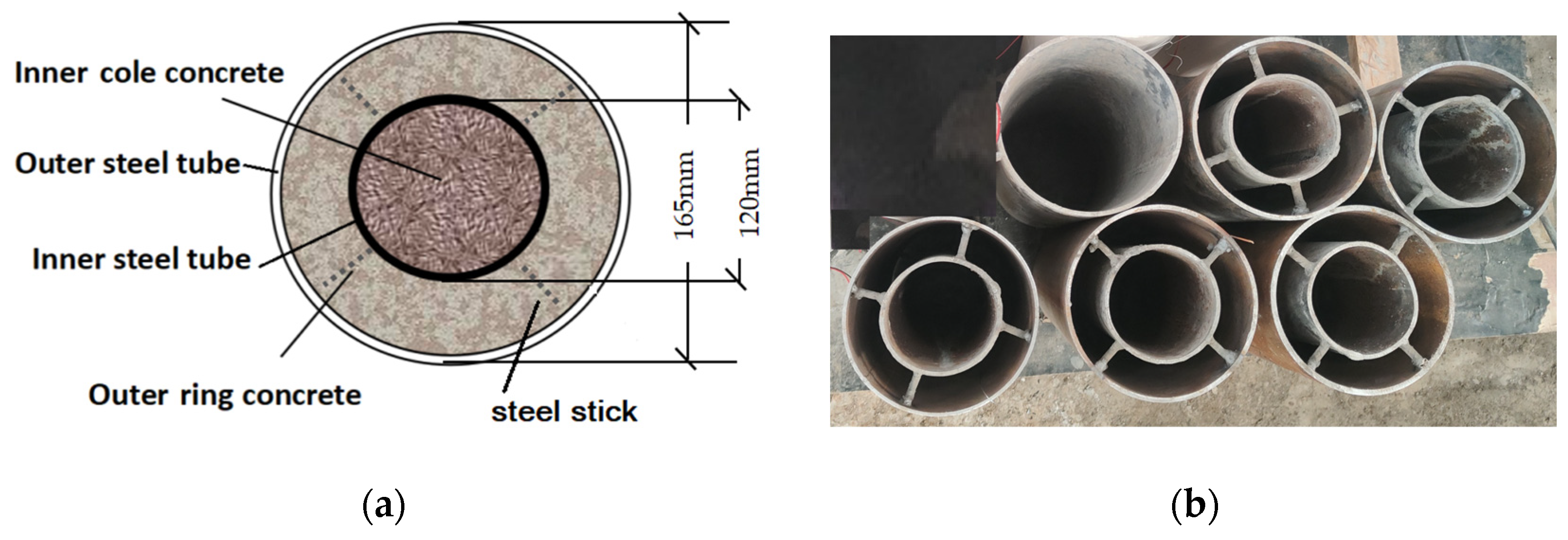
2.1. Test Specimens
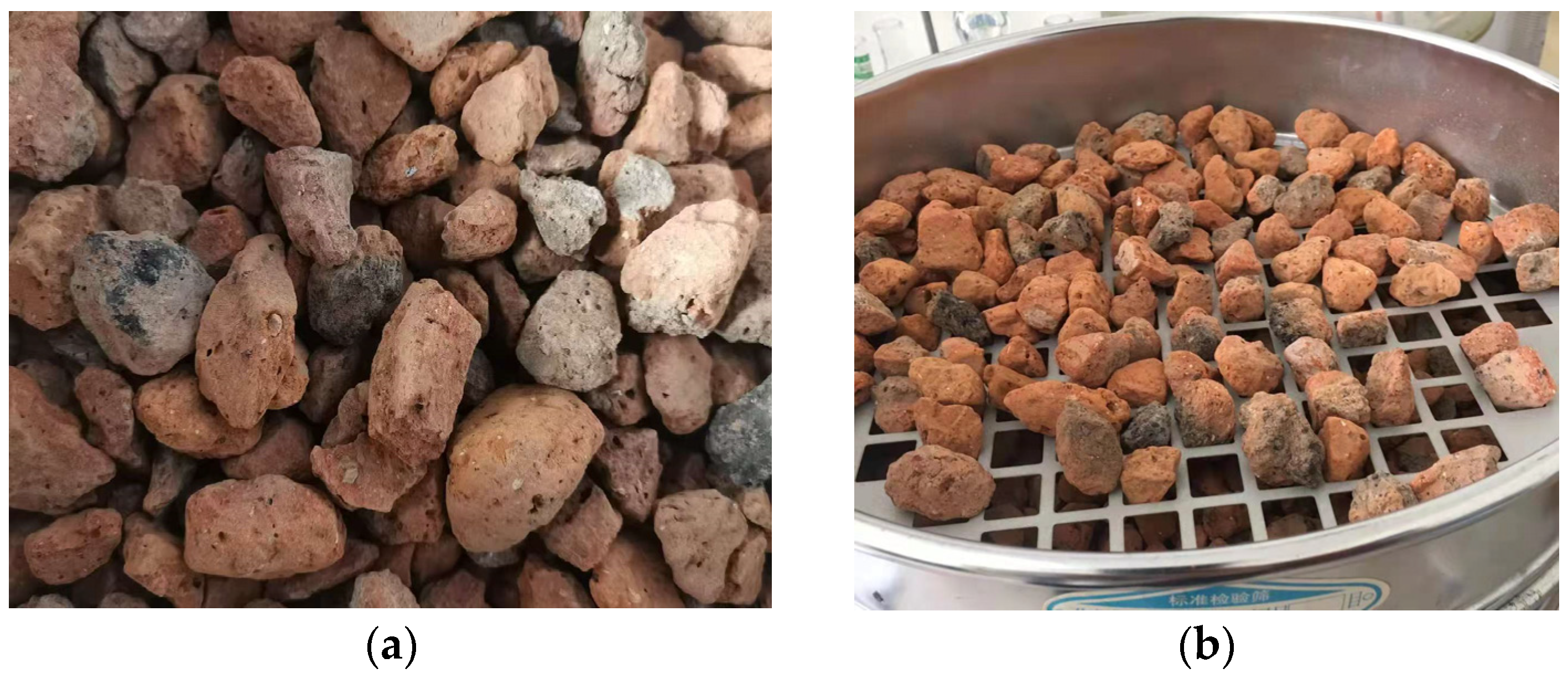
2.2. Materials
2.2.1. Concrete
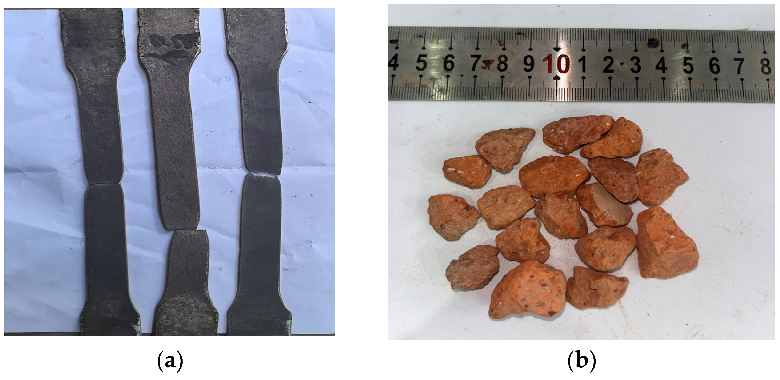
2.2.2. Steel
2.3. Experimental Instrumentation
2.4. Test Procedure
3. Test Results and Discussion
3.1. Test Phenomenon and Failure Modes
3.2. Ultimate Load Analysis
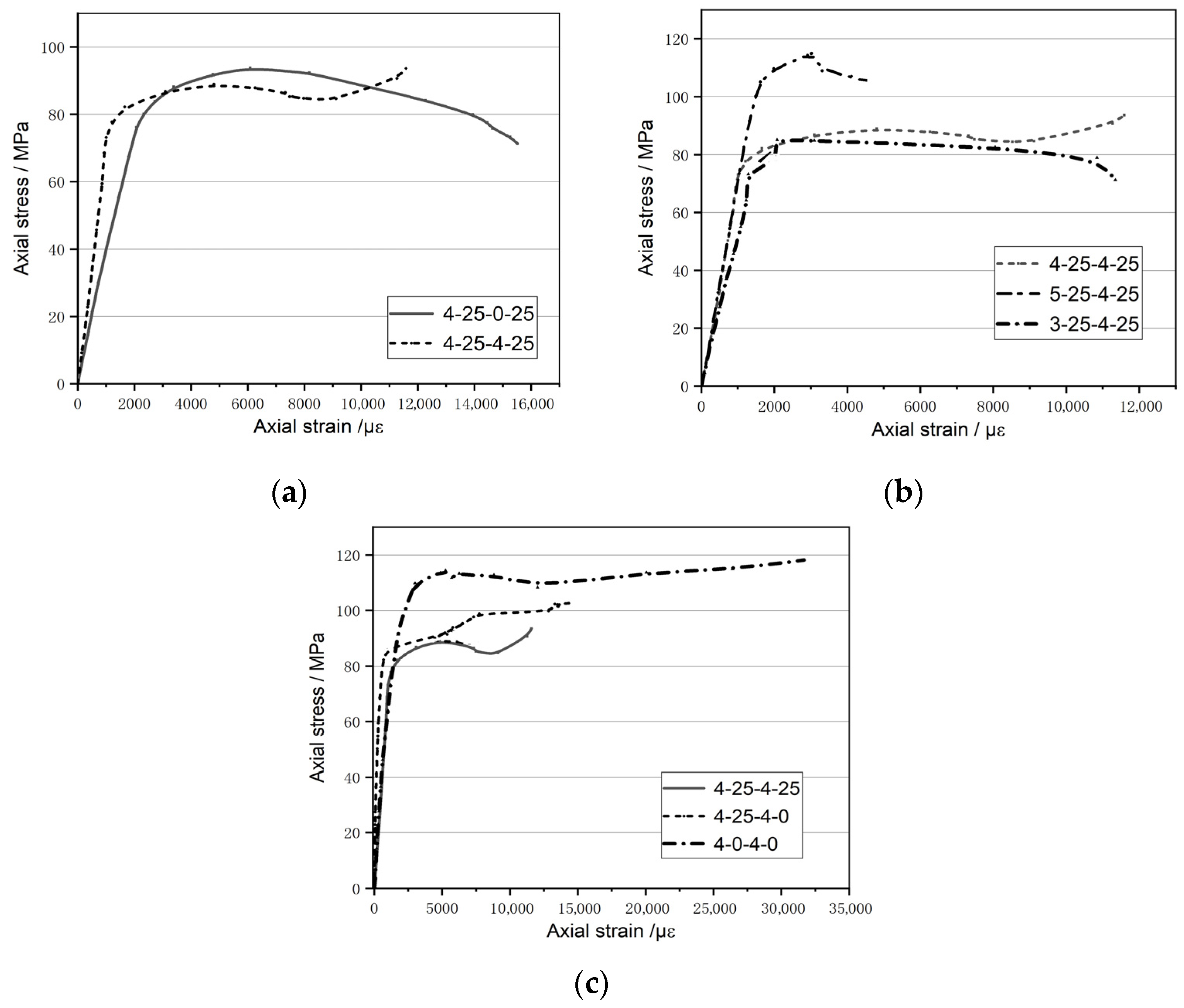
3.3. Axial Stress–Strain Curve Analysis
3.4. Transverse Strain Analysis
4. Constitutive Model of Double-Confined RBAC
4.1. Constitutive Model of Steel Tube
4.2. Constitutive Model of Confined RBAC
4.3. Constitutive Model of Double-Confined RAC
4.4. Proposed Constitutive Model of Double-Steel-Tube-Confined Core RBAC
5. Model Validation of FEM
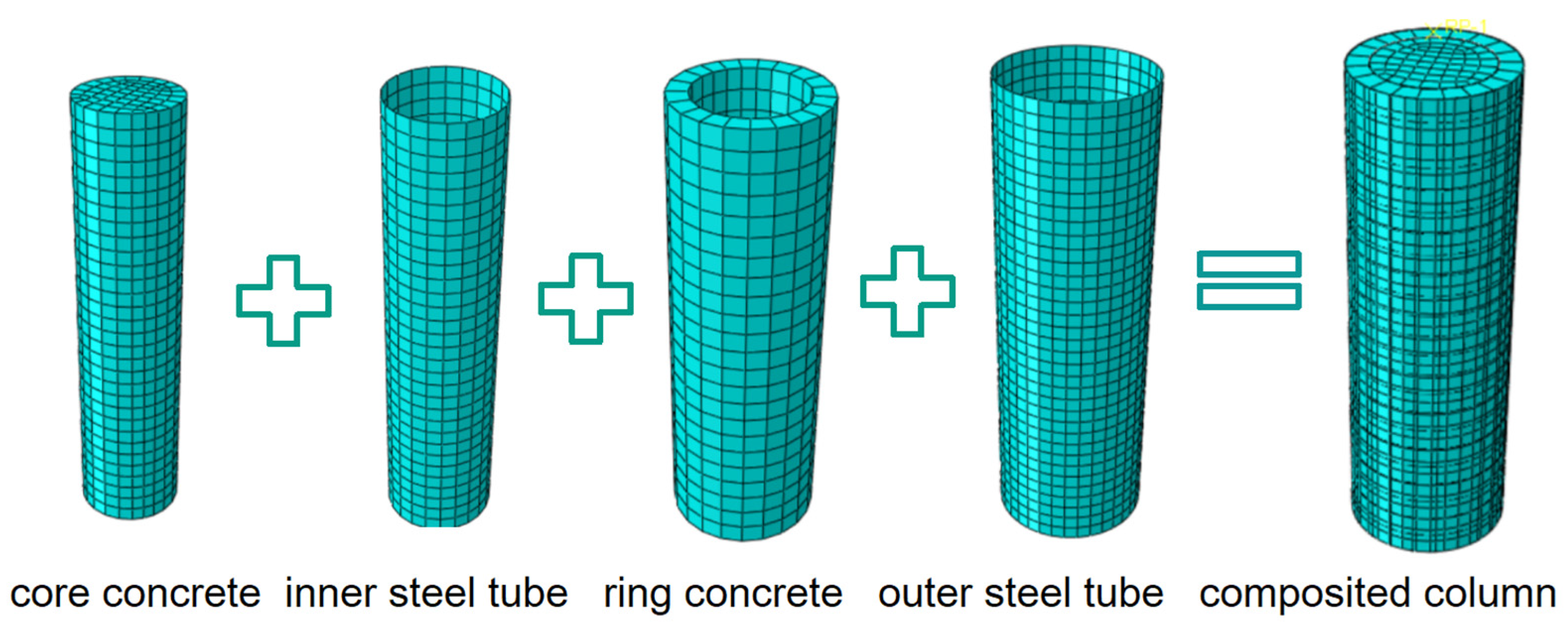
5.1. Model Establishment
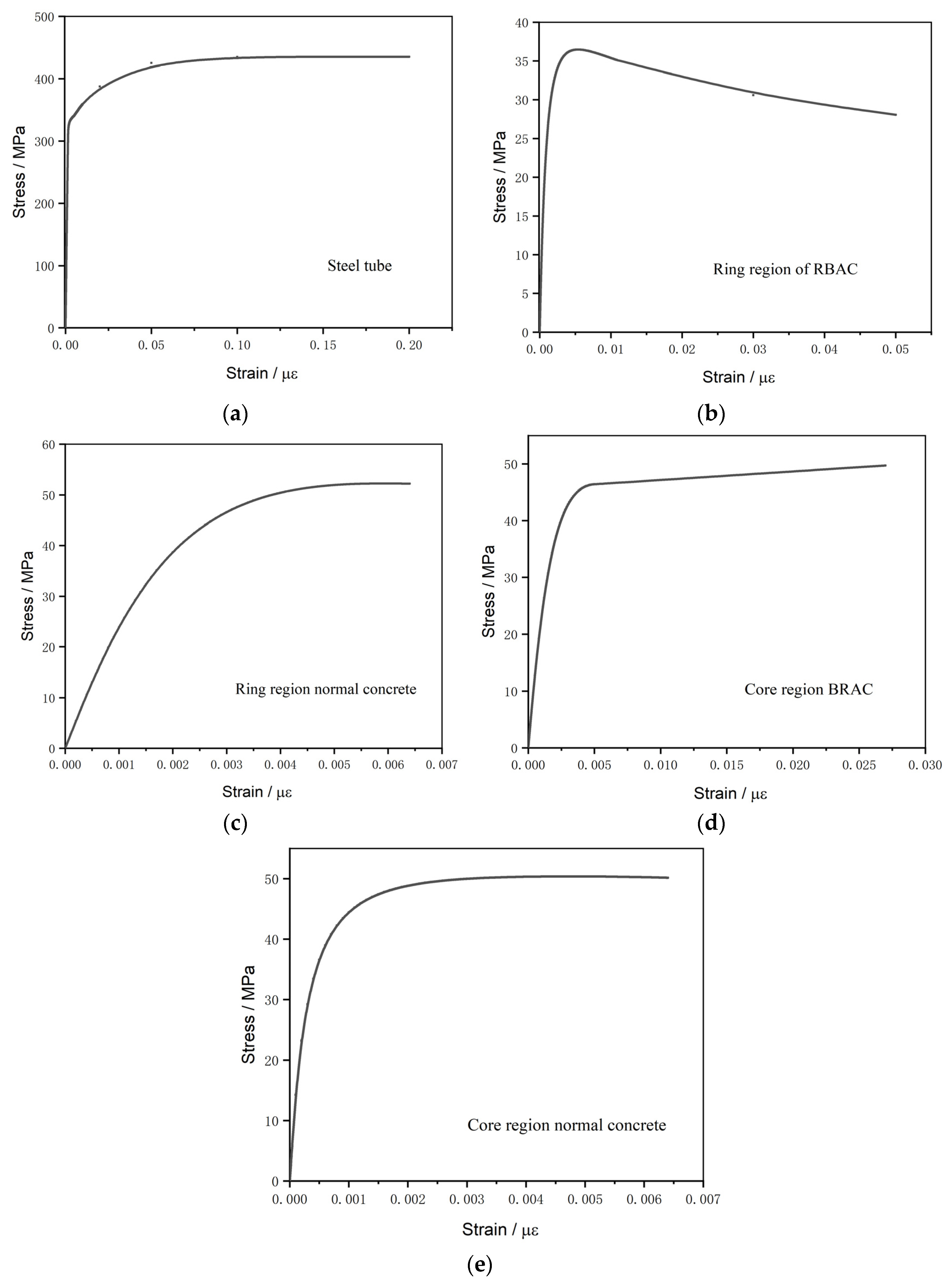
5.2. Material Model
5.3. Loading and Boundary Condition
5.4. Interaction and Surface
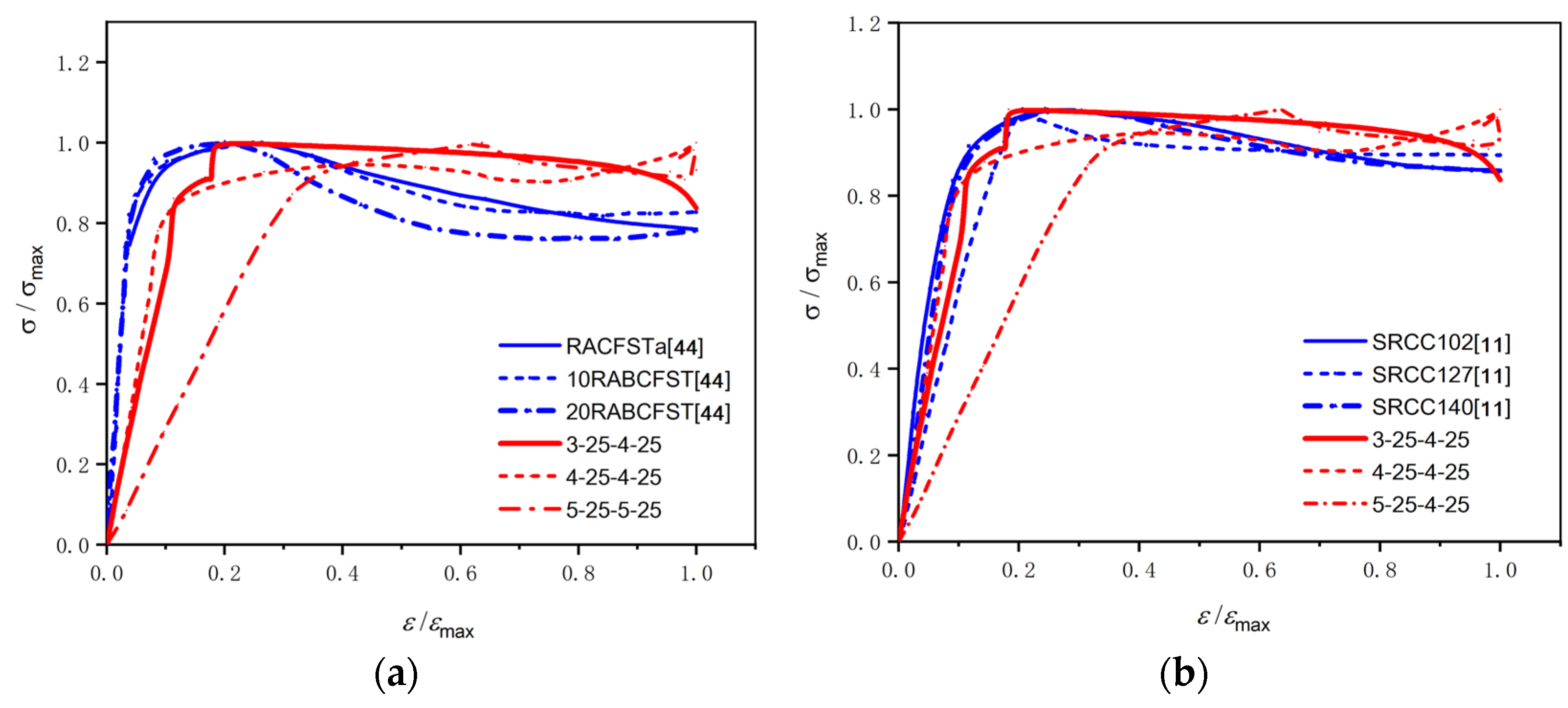
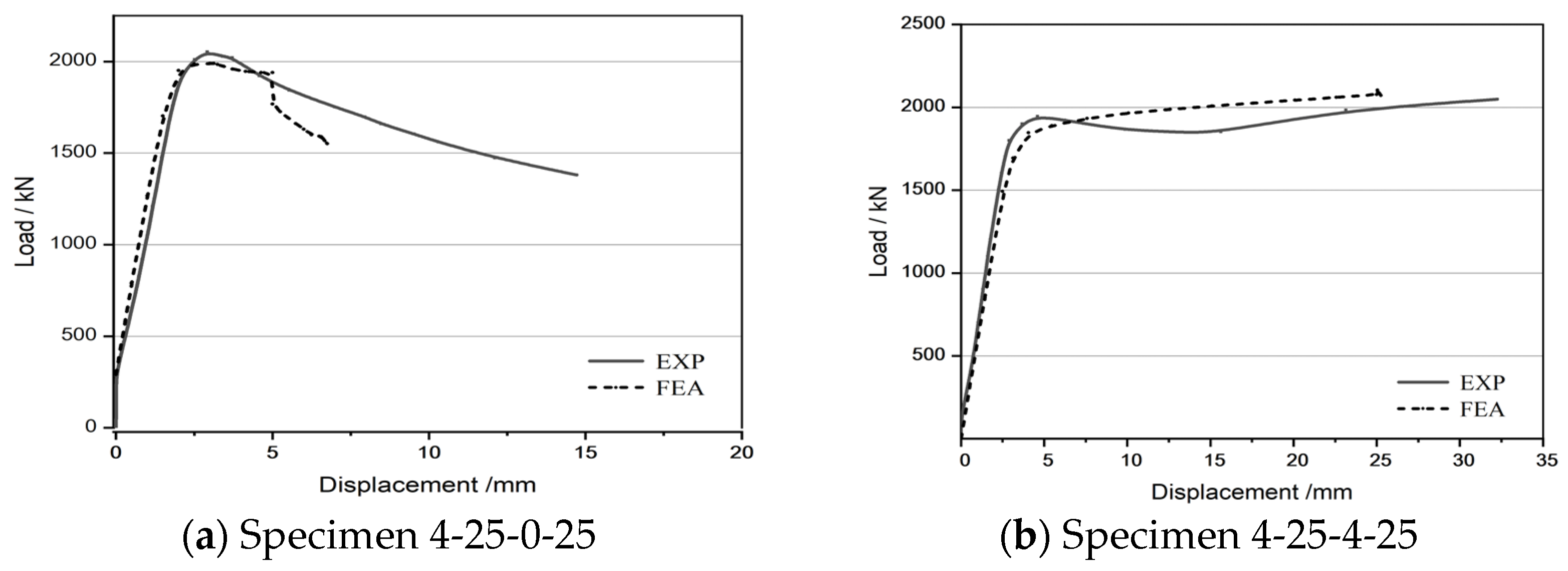
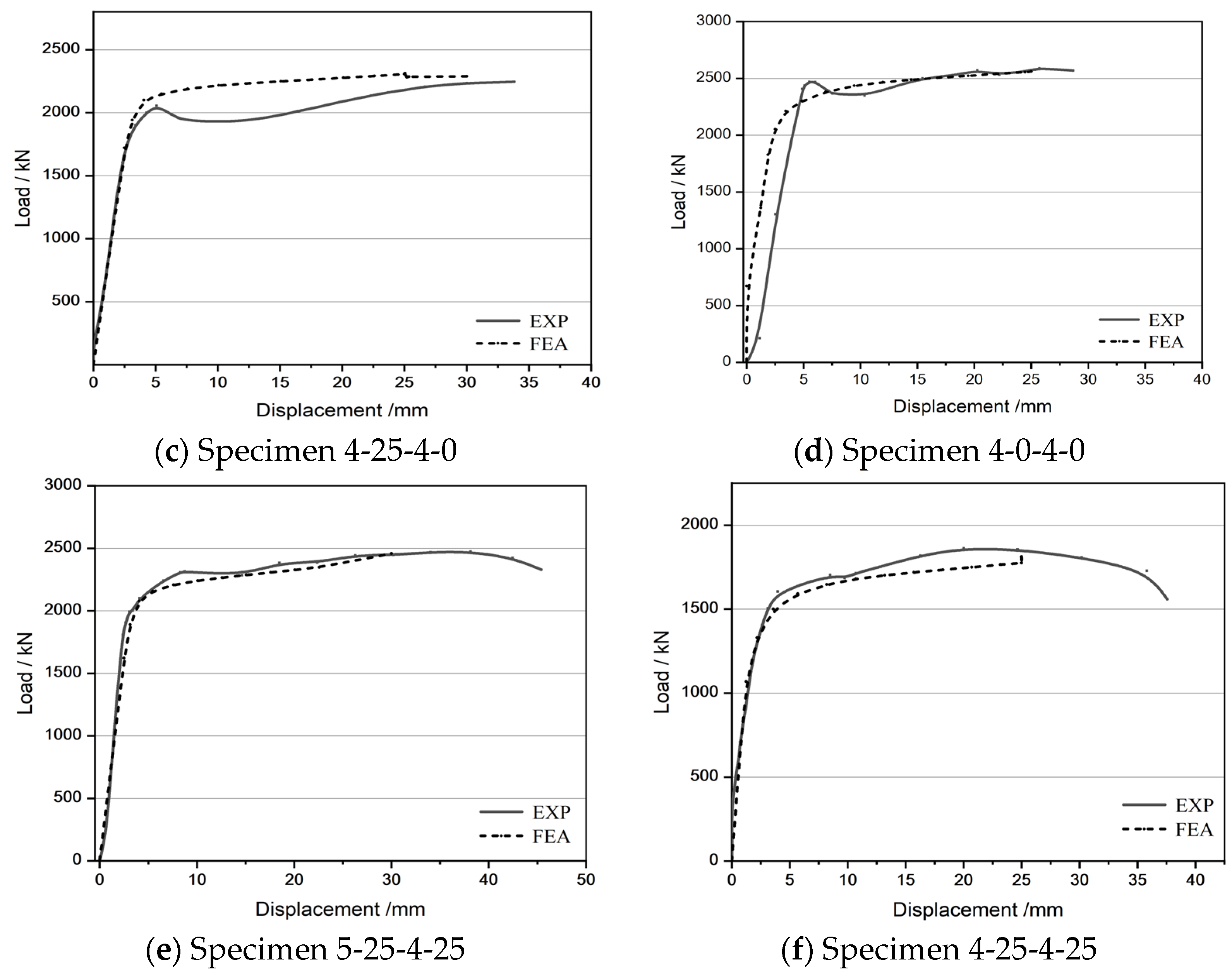
5.5. Verification of Model
5.6. Parametric Study
5.6.1. Influence of Diameter-to-Thickness Ratio of Outer Tube (D0/t0)
5.6.2. Influence of Diameter-to-Thickness Ratio of Inner Tube (Di/ti)
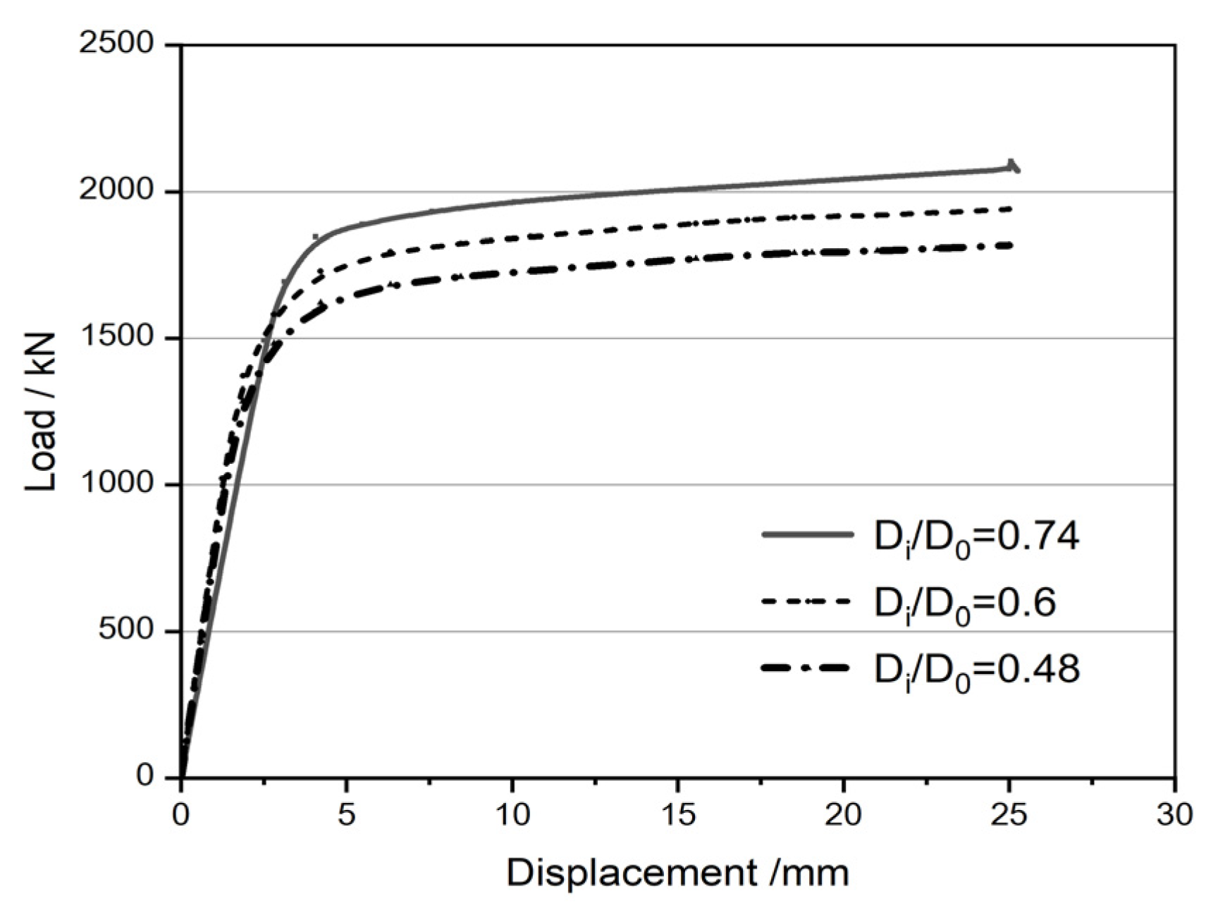
5.6.3. Influence of Diameter Ratio of Inner and Outer Tube (Di/D0)
6. Conclusions
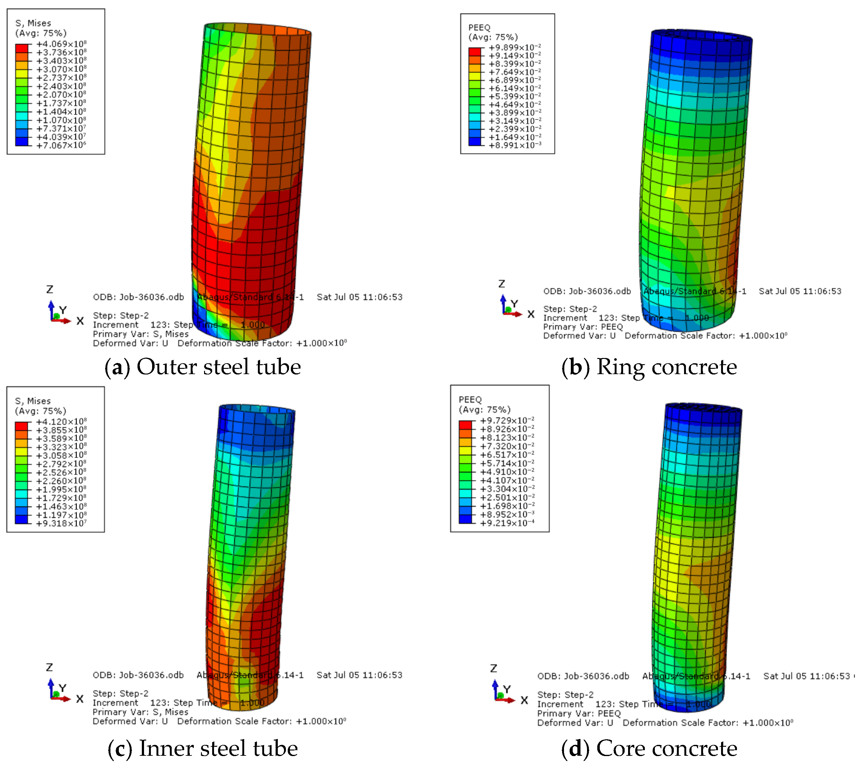
- The recycled-brick-aggregate-concrete-filled single-steel-tube column exhibits a clear shear failure mode under axial load. Double-steel-tube confinement can effectively change the failure mode. The buckling is only concentrated on the outer steel tube, approximately located within the range of a half to a third of the specimen height, whereas the inner steel tube has a relatively low rate of deformation.
- The ultimate strength of specimens is related to the replaced ratio of brick aggregate content, diameter-to-thickness ratio of the outer and inner steel tube, and outer and inner tube diameter ratio. Under the same double steel tube condition, if 25% brick aggregate recycled concrete is used only in the ring area of the section, the ultimate strength will be reduced by 9.1%. If 25% brick aggregate recycled concrete is adopted in the whole section, the ultimate strength will be reduced by 17.4%. Under the same concrete condition, the ultimate strength of the specimen improved with increasing of outer and inner steel tube diameters. For each 1 mm increase in the thickness of the outer tube, the maximum increase in the ultimate strength of the component can reach 22.6%. For each 1 mm increase in the thickness of the inner tube, the maximum increase in the ultimate strength of the component is just 4.1%.
- The double-steel-tube-confined recycled brick aggregate concrete column has two kinds of stress–strain curves. One is “full and convex”, while the other is “concave” with a secondary ascending phase. The shape of these curves reflects the suitability of the constraint combination. Excessive constraints may result in premature cracking of brick aggregates. Specimens 4-25-4-0 and 3-25-4-25 are relatively suitable combinations.
- A constitutive relationship of double-confined brick recycled aggregate concrete was proposed based on the existing literature, which can be used to express the mechanical behavior of inner core concrete in a double steel tube column.
- Finite element analysis shows that, as the diameter-to-thickness ratio of the inner and outer steel tubes decreases, the specimens’ ultimate strength shows an increasing trend. However, relatively speaking, the influence of the inner steel tube is not as obvious as that of the outer steel tube. The closer the diameters of the inner and outer steel tubes, the higher the ultimate strength obtained. Therefore, more attention should be paid to the restraint effect of the outer steel pipe during reinforcement.
Author Contributions
Funding
Data Availability Statement
Conflicts of Interest
Abbreviations
| CFDSTC | Concrete-filled double steel tubular column |
| RBCDST | Recycled-brick-aggregate-concrete-filled double steel tube |
| DSTC | Double steel tube column |
| C&D | Construction and demolition |
| RA | Recycled aggregate |
| RAC | Recycled aggregate concrete |
| ITZ | Interfacial transition zone |
| CFST | Concrete-filled steel tube |
| GFRP | Glass-fiber-reinforced polymer |
| RBAC | Recycled brick aggregate concrete |
| RBA | Recycled brick aggregate |
| CFRP | Carbon-fiber-reinforced polymer |
| HFRP | Hybrid-fiber-reinforced polymer |
| NA | Natural aggregates |
| LVDT | Linear variable differential transducer |
| FEM | Finite element method |
| σs | axial steel stress |
| εs | steel strain |
| fsy | steel yield strength |
| εsy | steel yield strain |
| εst | strain at the onset of strain-hardening |
| εsu | elastic modulus of steel tube |
| σc,v | stress of specimen |
| fcc’ | peak strength of confined concrete |
| fcu | cube crushing strength of concrete |
| cα, cfy, cfcu | Calculated parameter |
| εc,v | Peak strain of confined concrete |
| Εccb | Peak strain of RBAC |
| rCCB | Contained ratio of brick |
| Ecb | Elastic modulus of RBAC |
| Ecr | Elastic modulus of RAC |
| fl | Lateral confining pressure |
| w | Confinement ratio |
| ts | Thickness of steel tube |
| Ds | Cylinder diameter |
| ρk | Confining stiffness ratio |
| ρε | Strain ratio |
| fcc1 | Ultimate strength of single-confined concrete |
| fcc2 | Ultimate strength of double-confined concrete |
| εcc1 | Ultimate strain of single-confined concrete |
| εcc2 | Ultimate strain of double-confined concrete |
| λ | Index control the initial slope and the curvature of the ascending branch |
| fcr | Concrete residual strength |
| εci | Concrete strain corresponding to the inflection point |
| Dc | Concrete-core diameter of circular CFST column |
| D0 | Diameter of outer steel tube |
| Di | Diameter of inner steel tube |
| As0 | Cross-sectional areas of the outer tube |
| Asi | Cross-sectional areas of the inner tube |
| Asc | Cross-sectional areas of the ring concrete |
| Acc | Cross-sectional areas of the core concrete |
| fcc’ | Strengths of the core concrete |
| fsc’ | Strengths of the ring concrete |
| fsyi | Yield stress of the inner tube |
| fsy0 | Yield stress of the outer tube |
| t0 | Thickness of outer tube |
| ti | Thickness of inner tube |
References
- Xie, T.; Gholampour, A.; Ozbakkaloglu, T. Toward the Develop of Sustainable Concretes with Recycled Concrete Aggregateds: Comprehensive Review of Studies on Mechanical Properties. J. Mater. Eng. 2018, 30, 04018211. [Google Scholar]
- Kisku, N.; Joshi, H.; Ansari, M.; Panda, S.K.; Nayak, S.; Dutta, S.C. A critical review and assessment for usage of recycled aggregate as sustainable construction material. Constr. Build. Mater. 2017, 131, 721–740. [Google Scholar] [CrossRef]
- Kanellopoulos, A.; Nicolaides, D.; Petrou, M.F. Mechanical and durability properties of concretes containing recycled lime powder and RAs. Constr. Build. Mater. 2014, 53, 253–259. [Google Scholar] [CrossRef]
- Kwan, W.H.; Ramli, M.; Kam, K.J.; Sulieman, M.Z. Influence of the amount of recycled coarse aggregate in concrete design and durability properties. Constr. Build. Mater. 2012, 26, 565–573. [Google Scholar] [CrossRef]
- Bravo, M.; de Brito, J.; Pontes, J.; Evangelista, L. Durability performance of concrete with RAs from construction and demolition waste plants. Constr. Build. Mater. 2015, 77, 357–369. [Google Scholar] [CrossRef]
- Rao, M.C.; Bhattacharyya, S.K.; Barai, S.V. Influence of field recycled coarse aggregate on properties of concrete. Mater. Struct. 2011, 44, 205–220. [Google Scholar]
- Suryawanshi, S.R.; Singh, B.; Bhargava, P. Characterization of RAC, Advances in Structural Engineering; Springer: New Delhi, India, 2015; pp. 1813–1822. [Google Scholar]
- Kou, S.C.; Poon, C.S. Effect of the quality of parent concrete on the properties of high performance RAC. Constr. Build. Mater. 2015, 77, 501–508. [Google Scholar] [CrossRef]
- Matar, P.; Assaad, J.J. Concurrent effects of recycled aggregates and polypropylene fibers on workability and key strength properties of self-consolidating concrete. Constr. Build. Mater. 2015, 199, 492–500. [Google Scholar] [CrossRef]
- Meng, D.; Wu, X.M.; Quan, H.Z.; Zhu, C.J. A strength-based mix design method for recycled aggregate concrete and consequent durability performance. Constr. Build. Mater. 2021, 281, 122616. [Google Scholar] [CrossRef]
- Rong, C.; Qv, Y.; Shi, Q.; Wang, P.; Li, C. Axial behaviors of recycled aggregate concrete cylinders under various confinement types: The experimental and theoretical analysis. Constr. Build. Mater. 2022, 340, 127821. [Google Scholar] [CrossRef]
- Zeng, L.; Wu, L.; Li, B.; Fang, S.; Mohamed, H.S.; Fang, Z. Recycled aggregate concrete-filled steel tube columns with small-diameter circular FRP-confined sea-sand concrete cores: Conceptual and experimental investigations. Constr. Build. Mater. 2023, 401, 132853. [Google Scholar] [CrossRef]
- Zhao, H.; Zhang, W.H.; Wang, R.; Hou, C.-C.; Lam, D. Axial compression behaviour of round-ended recycled aggregate concrete-filled steel tube stub columns (RE-RACFST):experiment, numerical modeling and design. Eng. Struct. 2023, 276, 115376. [Google Scholar] [CrossRef]
- Tang, H.; Chen, J.; Fan, L.; Sun, X.; Peng, C. Experimental investigation of FRP-confined concrete-filled stainless steel tube stub columns under axial compression. Thin-Walled Struct. 2020, 146, 106483. [Google Scholar] [CrossRef]
- Tao, Z.; Hasan, M.; Han, D.; Qin, Q.; Ghafar, W.A. Study of the Axial Compressive Behaviour of Cross-Shaped CFST and ST Columns with Inner Changes. Buildings 2023, 13, 423. [Google Scholar] [CrossRef]
- Hasan, M.; Tao, Z.; Ghafar, W.A.; Huangfu, S.-E.; Zhang, Z. Investigating the axial compressive behavior of cruciform CFST columns: An experimental study. Structures 2024, 69, 107538. [Google Scholar] [CrossRef]
- Han, D.; Tao, Z.; Ghafar, W.A.; Hasan, M.; Xiao, W.; Wang, T.; Zhou, K.; Dai, H. Experimental Study on the Seismic Performance of L-Shaped CFST Columns in Different Combinations. Buildings 2023, 13, 2320. [Google Scholar] [CrossRef]
- Nikolic, J.; Tosic, N.; Murcia-Delso, J.; Kostic, S.M. Comprehensive review of the structural behaviour and numerical modelling of recycled aggregate concrete-filled steel tubes. Eng. Struct. 2024, 303, 117514. [Google Scholar] [CrossRef]
- Nour, A.I.; Güneyisi, E.M. Prediction model on the compressive strength of recycled aggregate concrete filled steel tube columns. Compos. Part B Eng. 2019, 173, 106938. [Google Scholar] [CrossRef]
- Yuan, H.; Chen, Y.; Kang, L.; Geng, T.; Ma, K. Compressive axial load performance of GFRP–confined recycled aggregate concrete–filled steel tube stub columns. J. Constr. Steel Res. 2024, 220, 108835. [Google Scholar] [CrossRef]
- Bai, Y.-L.; Zhang, Y.-F.; Jia, J.-F.; Han, Q.; Gao, W.-Y. Compressive behavior of double-skin tubular stub columns with recycled aggregate concrete and a PET FRP jacket. Constr. Build. Mater. 2022, 332, 127321. [Google Scholar] [CrossRef]
- Xiong, Z.; Deng, J.; Liu, F.; Li, L.; Feng, W. Experimental investigation on the behavior of GFRP-RAC-steel double-skin tubular columns under axial compression. Thin-Walled Struct. 2018, 132, 350–361. [Google Scholar] [CrossRef]
- Xiong, M.-X.; Chen, G.; Long, Y.-L.; Cui, H.; Liu, Y. Steel and FRP double-tube confined RAC columns under compression: Comparative study and stress-strain model. Steel Compos. Struct. 2022, 43, 257–270. [Google Scholar]
- Guo, Y.-C.; Ye, Y.-Y.; Lin, G.; Lv, J.-F.; Bai, Y.-L.; Zeng, J.-J. Effective usage of high strength steel tubes: Axial compressive behavior of hybrid FRP-concrete-steel solid columns. Thin-Walled Struct. 2020, 154, 106796. [Google Scholar] [CrossRef]
- Huang, L.; Xie, J.; Huang, J.; Li, L.; Lu, Z.; Huang, P. Compressive behaviour of GFRP-confined geopolymeric recycled aggregate concrete: Effects of RA content, GRAC size and confinement ratio. Eng. Struct. 2023, 291, 116421. [Google Scholar] [CrossRef]
- Yu, Q.; Ma, T.; Zhang, T.; Guo, Y.; Chen, C.; Wu, Z.; Wei, J. The influence of the particle size of recycled brick powder on the hydration kinetics and microstructure development of cement. J. South China Univ. Technol. (Nat. Sci. Ed.) 2023, 51, 63–73. [Google Scholar]
- Ejaz, A.; Ruangrassamee, A.; Jirawattanasomkul, T.; Zhang, D. Experimental and analytical investigations on enhancing compressive stress vs. strain response of square-section recycled brick aggregate concrete by steel clamps. Case Stud. Constr. Mater. 2025, 22, e04645. [Google Scholar] [CrossRef]
- Saingam, P.; Hussain, Q.; Sua-Iam, G.; Nawaz, A.; Ejaz, A. Hemp Fiber-Reinforced Polymers Composite Jacketing Technique for Sustainable and Environment-Friendly Concrete. Polymers 2024, 16, 1774. [Google Scholar] [CrossRef] [PubMed]
- Saingam, P.; Ejaz, A.; Ali, N.; Nawaz, A.; Hussain, Q.; Joyklad, P. Prediction of Stress–Strain Curves for HFRP Composite Confined Brick Aggregate Concrete under Axial Load. Polymers 2023, 15, 844. [Google Scholar] [CrossRef]
- Chaiyasarn, K.; Poovarodom, N.; Ejaz, A.; Ng, A.W.; Hussain, Q.; Saingam, P.; Mohamad, H.; Joyklad, P. Influence of natural fiber rope wrapping techniques on the compressive response of recycled aggregate concrete circular columns. Results Eng. 2023, 19, 101291. [Google Scholar] [CrossRef]
- Joyklad, P.; Saingam, P.; Ali, N.; Ejaz, A.; Hussain, Q.; Khan, K.; Chaiyasarn, K. Low-Cost Fiber Chopped Strand Mat Composites for Compressive Stress and Strain Enhancement of Concrete Made with Brick Waste Aggregates. Polymers 2022, 14, 4714. [Google Scholar] [CrossRef]
- Yan, B.; Huang, L.; Yan, L.; Gao, C.; Kasal, B. Behavior of flax FRP tube encased recycled aggregate concrete with clay brick aggregate. Constr. Build. Mater. 2017, 136, 265–276. [Google Scholar] [CrossRef]
- Jiang, T.; Wang, X.M.; Zhang, W.P.; Chen, G.M.; Lin, Z.H. Lin. Behavior of FRP-Confined Recycled Brick Aggregate Concrete under Monotonic Compression. J. Compos. Constr. 2020, 24, 04020067. [Google Scholar] [CrossRef]
- Gao, C.; Huang, L.; Yan, L.; Kasal, B.; Li, W. Behavior of Glass and Carbon FRP Tube Encased Recycled Aggregate Concrete with Recycled Clay Brick Aggregate. Compos. Struct. 2016, 155, 245–254. [Google Scholar] [CrossRef]
- Huang, L.; Chen, L.; Yan, L.; Kasal, B.; Jiang, Y.; Liu, C. Behavior of polyester FRP tube encased recycled aggregate concrete with recycled clay brick aggregate: Size and slenderness ratio effects. Constr. Build. Mater. 2017, 154, 123–136. [Google Scholar] [CrossRef]
- Jiang, T.; Wang, X.; Chen, G.; Zhang, J.; Zhang, W. Behavior of recycled brick block concrete-filled FRP tubes under axial compression. Eng. Struct. 2019, 198, 109498. [Google Scholar] [CrossRef]
- Huang, L.; Liang, J.; Gao, C.; Yan, L. Flax FRP tube and steel spiral dual-confined recycled aggregate concrete: Experimental and analytical studies. Constr. Build. Mater. 2021, 300, 124023. [Google Scholar] [CrossRef]
- Gao, C.; Huang, L.; Yan, L.; Jin, R.; Kasal, B. Strength and ductility improvement of recycled aggregate concrete by polyester FRP-PVC tube confinement. Compos. Part B Eng. 2019, 162, 178–197. [Google Scholar] [CrossRef]
- Long, Y.-L.; Li, W.-T.; Dai, J.-G.; Gardner, L. Experimental study of concrete-filled CHS stub columns with inner FRP tubes. Thin-Walled Struct. 2018, 122, 606–621. [Google Scholar] [CrossRef]
- Sun, Y.; Hou, D.; Shi, Y.; Sun, Y.; Xv, C.; Wang, Y. Mechanical Properties of Recycled Concrete Containing Brick–Concrete Waste Aggregates with Basalt Fiber-Reinforced Polymer (BFRP) Fibers. Buildings 2025, 15, 2047. [Google Scholar] [CrossRef]
- GB/T50081-2019; Standard for Test Methods of Concrete Physical and Mechanical Properties. Ministry of Housing and Urban-Rural Development of the People’s Republic of China (MOHURD): Beijing, China, 2019.
- GB/T228.1—2021; Metallic Materials—Tensile Testing—Part1: Method of Test at Room Temperature. 51. State Administration for Market Regulation and Standardization Administration of the People’s Republic of China: Beijing, China, 2022.
- Ekmekyapar, T.; Al-Eliwi, B.J. Concrete filled double circular steel tube (CFDCST) stub columns. Eng. Struct. 2017, 135, 68–80. [Google Scholar] [CrossRef]
- Chen, J.; Zhang, S.; Wang, Y.; Geng, Y. Axial compressive behavior of recycled concrete filled steel tubular stub columns with the inclusion of crushed brick. Structures 2020, 26, 271–283. [Google Scholar] [CrossRef]
- Ahmed, M.; Liang, Q.; Patel, V.I.; Hadi, M.N.S. Numerical analysis of axially loaded circular high strength concrete-filled double steel tubular short columns. Thin-Walled Struct. 2019, 138, 105–116. [Google Scholar] [CrossRef]
- Liang, Q.Q. Performance-based analysis of concrete-filled steel tubular beam—Columns, Part I: Theory and algorithms. J. Constr. Steel Res. 2009, 65, 363–372. [Google Scholar] [CrossRef]
- Mander, J.B. Seismic Design of Bridge Piers. Ph.D. Thesis, Department of Civil Engineering of University of Canterbury, Christchurch, New Zealand, 1983. [Google Scholar]
- Mander, J.B.; Priestley, M.J.N.; Park, R. Theoretical stress-strain model for confined concrete. ASCE J. Struct. Eng. 1988, 114, 1804–1826. [Google Scholar] [CrossRef]
- Wang, Y.; Chen, J.; Geng, Y. Testing and analysis of axially loaded normal-strength recycled aggregate concrete filled steel tubular stub columns. Eng. Struct. 2015, 86, 192–212. [Google Scholar] [CrossRef]
- Tao, Z.; Han, L.-H.; Zhao, X.-L. Behaviour of concrete-filled double skin (CHS inner and CHS outer) steel tubular stub columns and beam-columns. J. Constr. Steel Res. 2004, 60, 1129–1158. [Google Scholar] [CrossRef]
- Zheng, Y.; Du, J.; Zheng, L.; Wang, C. Compressive behavior of geopolymer recycled brick aggregate concrete confined by steel tubes. J. Build. Eng. 2023, 70, 106350. [Google Scholar] [CrossRef]
- Wu, K.; Chen, F.; Zhang, H.; Xu, C.; Lin, S.-Q. Experimental study on the behavior of recycled concrete-filled thin-wall steel tube columns under axial compression. Arab. J. Sci. Eng. 2018, 43, 5225–5242. [Google Scholar] [CrossRef]
- Lam, L.; Teng, J.G. Design-oriented stress-strain model for FRP-confined concrete in rectangular columns. Constr. Build. Mater. 2009, 17, 471–489. [Google Scholar] [CrossRef]
- Lim, J.C.; Ozbakkaloglu, T. Stress-strain model for normal-and light-weight concretes under uniaxial and triaxial compression. Constr. Build. Mater. 2014, 71, 492–509. [Google Scholar] [CrossRef]
- Ahmed, M.; Liang, Q.Q.; Patel, V.I.; Hadi, M.N.S. Nonlinear analysis of rectangular concrete-filled double steel tubular short columns incorporating local buckling. Eng. Struct. 2018, 175, 13–26. [Google Scholar] [CrossRef]
- De Nicolo, B.; Pani, L.; Pozzo, E. Strain of concrete at peak compressive stress for a wide range of compressive strengths. Mater. Struct. 1994, 27, 206–210. [Google Scholar] [CrossRef]
- Hu, H.T.; Huang, C.S.; Wu, M.H.; Wu, Y.M. Nonlinear analysis of axially loaded concrete-filled tube circular stub columns with confinemen effect. ASCE J. Struct. Eng. 2003, 129, 1322–1329. [Google Scholar] [CrossRef]


| No. | RBA Replacement Ratio of Inner Concrete /% | RBA Replacement Ratio of Ring Concrete /% | Thickness of Inner Steel Tube /mm | Thickness of Outer Steel Tube /mm |
|---|---|---|---|---|
| 4-25-0-25 | 25 | 25 | None | 4 |
| 4-25-4-25 | 25 | 25 | 4 | 4 |
| 4-25-4-0 | 0 | 25 | 4 | 4 |
| 4-0-4-0 | 0 | 0 | 4 | 4 |
| 5-25-5-25 | 25 | 25 | 4 | 5 |
| 3-25-4-25 | 25 | 25 | 4 | 3 |
| Aggregates | Apparent Density of Aggregate /kg/m3 | Crush Value /% | Water Absorption /% |
|---|---|---|---|
| NA | 2720 | 8.6 | 1.2 |
| RBA | 2340 | 33.2 | 15.2 |
| Cement kg/m3 | Water kg/m3 | NA kg/m3 | Fine Aggregates kg/m3 | RBA kg/m3 | RBA Replacement Ratio in Coarse Aggregates /% | Water-Reducing Admixture kg/m3 | Cube Compressive Strength of Concrete /MPa | Elastic Module /MPa |
|---|---|---|---|---|---|---|---|---|
| 540 | 165.0 | 790.0 | 900 | 0 | 0 | 16 | 51.7 | 30,446 |
| 540 | 195.0 | 592.5 | 900 | 197.5 | 25 | 16 | 39.8 | 20,807 |
| Number | Width /mm | Thickness /mm | Failure Load /kN | Yield Load /kN | Tensile Strength /MPa | Yield Strength /MPa |
|---|---|---|---|---|---|---|
| 1 | 20.0 | 3.0 | 31.6 | 24.7 | 395 | 310 |
| 2 | 20.0 | 4.0 | 34.9 | 30.0 | 435 | 340 |
| 3 | 20.0 | 5.0 | 47.6 | 33.9 | 475 | 375 |
| Name of Specimen | Ultimate Load /kN | Ultimate Strength /MPa |
|---|---|---|
| 4-25-0-25 | 2048.6 | 93.6 |
| 4-25-4-25 | 2052.9 | 93.7 |
| 4-0-4-0 | 2485.8 | 113.5 |
| 5-25-4-25 | 2516.8 | 114.9 |
| 3-25-4-25 | 1862.2 | 85.1 |
| Source | Specimen | Type | Concrete | Bearing Capacity Gain% |
|---|---|---|---|---|
| Rong et al. [11] | GRCC(5)-1,2 | GFRP | RAC | 1.2% |
| DRCC102(5)-1,2 | GFRP/steel | |||
| GRCC(8)-1,2 | GFRP | RAC | 25% | |
| DRCC140(8)-1,2 | GFRP/steel | |||
| YL Long et al. [39] | 1S0FL | Steel | Concrete | 12% |
| 1S1FL-100-2 | Steel/FRP | |||
| 1S1FL-150-2 | 22% | |||
| 1S1FL-200-2 | 30% | |||
| 1S0FH | 12% | |||
| 1S1FH-150-3 | ||||
| 1S1FH-200-3 | 19% | |||
| Talha et al. [43] | CC1-OT1 | Steel/steel | Concrete | - |
| CC1-SC1-OT1 | 66% | |||
| CC2-OT1 | - | |||
| CC2-SC1-OT1 | 32% |
| Materials | Formulas |
|---|---|
| Steel tube | Equation (1) |
| Ring region RBAC | Equations (2)–(14) |
| Ring region normal concrete | Equations (40)–(42) |
| Core region RBAC | Equations (24)–(30) |
| Core region normal concrete | Equations (31)–(39) |
Disclaimer/Publisher’s Note: The statements, opinions and data contained in all publications are solely those of the individual author(s) and contributor(s) and not of MDPI and/or the editor(s). MDPI and/or the editor(s) disclaim responsibility for any injury to people or property resulting from any ideas, methods, instructions or products referred to in the content. |
© 2025 by the authors. Licensee MDPI, Basel, Switzerland. This article is an open access article distributed under the terms and conditions of the Creative Commons Attribution (CC BY) license (https://creativecommons.org/licenses/by/4.0/).
Share and Cite
Sun, Y.; Hou, D.; Shi, Y.; Sun, Y.; Meng, F.; Chen, D. Experimental and Mechanism Study on Axial Compressive Performance of Double Steel Tube Columns Filled with Recycled Concrete Containing Abandoned Brick Aggregate. Buildings 2025, 15, 2424. https://doi.org/10.3390/buildings15142424
Sun Y, Hou D, Shi Y, Sun Y, Meng F, Chen D. Experimental and Mechanism Study on Axial Compressive Performance of Double Steel Tube Columns Filled with Recycled Concrete Containing Abandoned Brick Aggregate. Buildings. 2025; 15(14):2424. https://doi.org/10.3390/buildings15142424
Chicago/Turabian StyleSun, Yuanyuan, Dongxu Hou, Yanbiao Shi, Yamei Sun, Fancheng Meng, and Dong Chen. 2025. "Experimental and Mechanism Study on Axial Compressive Performance of Double Steel Tube Columns Filled with Recycled Concrete Containing Abandoned Brick Aggregate" Buildings 15, no. 14: 2424. https://doi.org/10.3390/buildings15142424
APA StyleSun, Y., Hou, D., Shi, Y., Sun, Y., Meng, F., & Chen, D. (2025). Experimental and Mechanism Study on Axial Compressive Performance of Double Steel Tube Columns Filled with Recycled Concrete Containing Abandoned Brick Aggregate. Buildings, 15(14), 2424. https://doi.org/10.3390/buildings15142424