Article

Calculation of Shear-Bearing Capacity of Aluminum Alloy-Concrete Composite Beam

1
School of Civil & Architecture Engineering, Xi’an Technological University, Xi’an 710021, China
2
School of Computing, Engineering and Physical Sciences, University of the West of Scotland, Glasgow PA1 2BE, UK
*
Author to whom correspondence should be addressed.
Buildings 2025, 15(14), 2393; https://doi.org/10.3390/buildings15142393
Submission received: 13 May 2025 / Revised: 5 June 2025 / Accepted: 10 June 2025 / Published: 8 July 2025
(This article belongs to the Section Building Structures)

Abstract

This study investigates the shear bearing capacity of aluminum alloy–concrete composite beams to address the limitations caused by the low elastic modulus of aluminum alloys. A finite element model was developed using the Concrete Damaged Plasticity (CDP) model for concrete and validated through parametric analysis. Key factors such as concrete strength, stirrup spacing, and cross-sectional dimensions were examined. An improved shear capacity formula was derived based on the tension–compression bar model and the superposition method. The proposed formula achieved an average ratio of 1.018 to finite element results, with a standard deviation of 0.151, and the proposed formula was validated against 22 FEA models, demonstrating excellent agreement with numerical results and confirming its reliability for practical engineering applications. This work provides a practical analytical approach for the shear design of aluminum–concrete composite structures.

1. Introduction

Some steel–concrete composite beams are designed with encased concrete, offering advantages such as high bearing capacity, enhanced durability, and effective control of steel deformation. However, during service, the steel components are prone to corrosion, and maintenance becomes challenging due to their encapsulation in concrete, resulting in increased lifecycle costs. To address these issues, a new structural form—an aluminum alloy–concrete composite beam—is proposed in this study. The cross-sectional design is based on the traditional encased concrete composite beam. Compared to steel, aluminum alloys possess superior properties such as corrosion resistance, maintenance-free performance, and high plasticity [1,2,3]. Therefore, in the proposed composite system, aluminum alloy beams replace steel beams, and aluminum alloy bars replace steel reinforcement to support the concrete, thereby mitigating problems associated with steel corrosion and difficult maintenance. Furthermore, casting concrete on both sides of the web of an H-shaped aluminum alloy beam can effectively prevent web buckling and enhance the strength and stability of the composite beam. This study addresses the absence of a validated method for calculating the shear bearing capacity of aluminum alloy–concrete composite beams, a structural form with increasing potential in corrosion-sensitive environments. The scientific novelty lies in adapting and extending the tension–compression bar model—traditionally used for steel–concrete systems—to aluminum-based composites. The main purpose of this research is to develop and validate a shear capacity formula that considers the distinct material and structural behavior of aluminum alloy. The specific objectives are as follows: (1) to construct accurate finite element models incorporating nonlinear concrete behavior; (2) to conduct parametric studies to evaluate key influencing factors; and (3) to derive and verify a predictive formula with practical engineering applicability.

2. Literature Review

Preliminary research on aluminum alloy–concrete composite beams abroad began in the last century, primarily focusing on bridge structures. Tomasz Siwowski (2006) [4] investigated aluminum lightweight concrete composite beams and found that the load-bearing capacity increased by approximately 50%. However, studies specifically addressing the shear bearing capacity of aluminum alloy–concrete composite beams remain limited internationally. Existing research primarily concentrates on the design and performance of shear connectors and their influencing factors. Between 2014 and 2019, Łukasz Polus and Maciej Szumigała [5,6,7,8,9] conducted a series of experimental investigations and finite element analyses on shear connectors and the shear performance of aluminum alloy–concrete composite beams. Due to the lack of a dedicated design code for aluminum alloy–concrete composite structures, studies have largely referenced the calculation methods outlined in Eurocode 4 [10] and related guidelines such as the North American Specification AISI S100 for cold-formed steel members [11]. In China, research on aluminum alloy–concrete composite beams has primarily focused on bending resistance [12], reinforcement methods [13], and bond–slip behavior [14], with few studies specifically addressing shear bearing capacity. However, recent numerical work has shown that adding external aluminum alloy plates can enhance the shear performance of RC beams [15]. Currently, only one review highlights the necessity of investigating the shear capacity of aluminum alloy–concrete composite beams [16].
To investigate the variation in shear bearing capacity of aluminum alloy–concrete composite beams and to derive a calculation formula, the main work of this study is summarized as follows:
(1) A three-dimensional finite element model of the aluminum alloy–concrete composite beam is established using a finite element analysis software package, incorporating an appropriate constitutive model for the aluminum alloy and a plastic damage constitutive model for the concrete; (2) finite element models with varying parameters—including shear span ratio, concrete strength, section dimensions, and stirrup spacing—are developed to analyze the influence of these factors on the shear capacity of aluminum alloy–concrete composite beams; (3) through theoretical analysis, the components contributing to the shear bearing capacity are identified, primarily considering the shear contributions of the aluminum alloy web and the concrete between the webs. The shear mechanism of the aluminum alloy–concrete composite beam is analyzed, and a corresponding mechanical model is established. Based on an improved tension–compression bar model, a formula for calculating the shear bearing capacity of aluminum alloy–concrete composite beams is derived.

3. Materials and Methods

3.1. Modeling Method

The section configuration and finite element model of the aluminum alloy–concrete composite beam are shown in Figure 1. Compared with the traditional section design, the shear connectors in this study are positioned on the lower flange for the following reasons: aluminum alloy materials exhibit a heat-affected zone (HAZ) during welding, which adversely affects the mechanical properties of the structure; consequently, strength reduction must be considered in calculations. In composite beams, the shear bearing capacity primarily depends on the web. Therefore, placing shear connectors on the web would reduce the shear strength of the aluminum alloy web. The section of the H-shaped aluminum alloy beam selected for the finite element model is H300 × 170 × 8 × 15 mm, and the concrete has a strength grade of C30. Aluminum alloy 6061-T6 (The material parameters for aluminum alloy 6061-T6 were obtained from the technical datasheet of Southwest Aluminum Co., Ltd. (Chongqing, China), a commonly used reference source in structural aluminum design.) is also used for stirrups and longitudinal reinforcement. The stirrup spacing is 150 mm, following the reinforcement layout.
The boundary conditions of the finite element model are defined according to the constraints of a simply supported beam, and a displacement-controlled loading method is adopted. A solid element model is established for the H-shaped aluminum alloy beam, concrete slab, and bolt connectors, while a truss element model is used for the aluminum alloy reinforcement bars. To simulate the interaction between the aluminum alloy beam and the concrete slab, a “hard” contact type with “surface-to-surface contact” is applied For the mutual constraints among the four components—aluminum alloy, concrete, aluminum alloy bars, and studs—the following approaches are adopted: the bottoms of the studs and the aluminum alloy web/lower flange are connected using a “tie” constraint, while an embedded connection is used to model the interaction between the concrete and both the aluminum alloy reinforcement bars and stud connectors.
Finite element analysis was performed using ABAQUS 2021. A mesh convergence study was conducted by comparing results using mesh sizes of 15 mm, 12 mm, and 10 mm. The mesh was considered converged when changes in peak load predictions were within 5%. Based on this, a 10 mm element size was adopted for all solid components.
Solid components (aluminum alloy beam, concrete slab, and studs) were modeled using eight-node linear brick elements with reduced integration (C3D8R). Reinforcing bars were modeled using two-node linear truss elements (T3D2). This discretization ensures a balance between computational efficiency and accuracy.

3.2. Constitutive Model

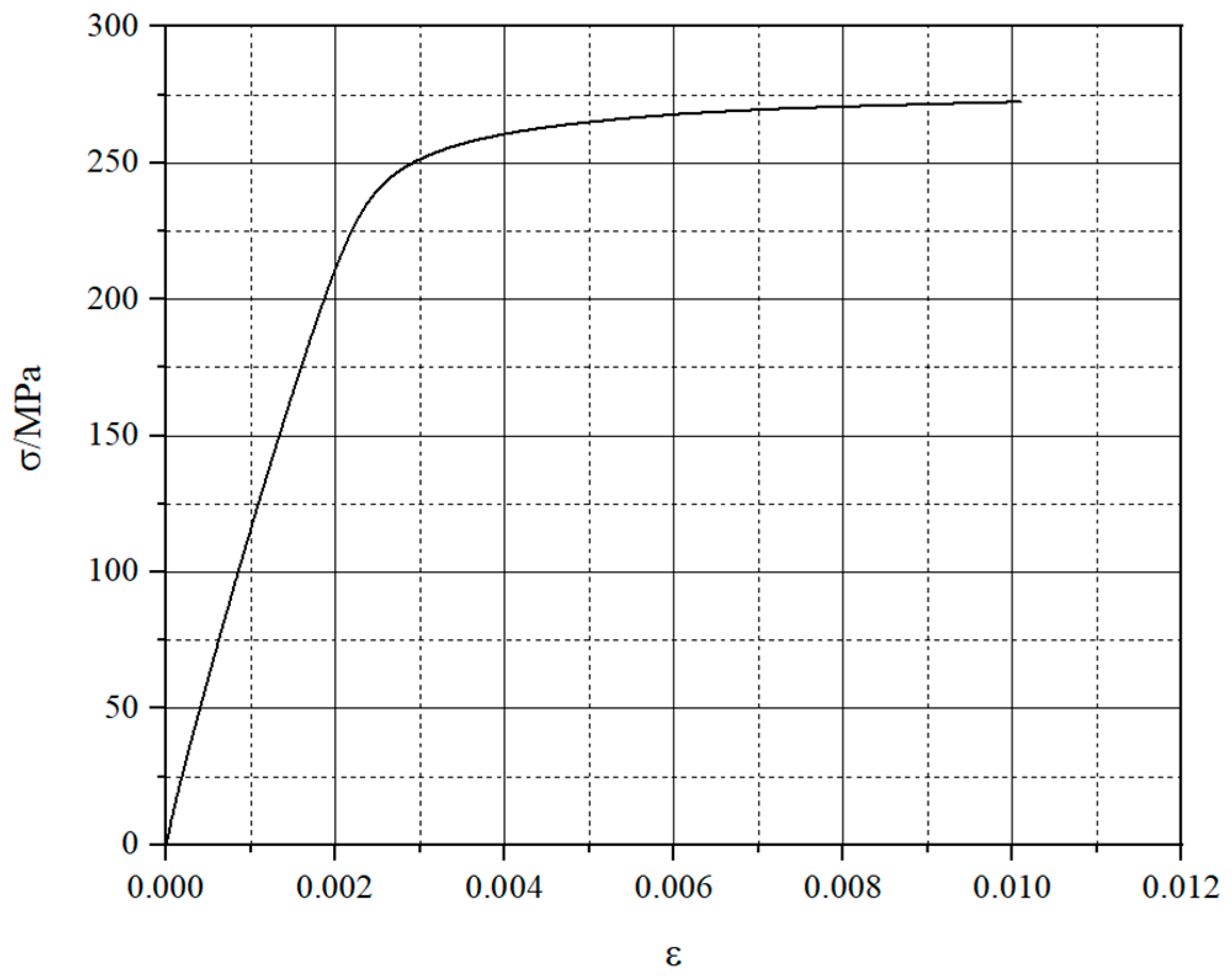
Ten groups of aluminum alloy 6061-T6 specimens were designed for material property testing, and nine groups of valid data were obtained After sorting and analyzing the test results and combining the Ramberg–Osgood model with Steinhardt’s proposed calculation formula [17,18], the constitutive relationship of aluminum alloy 6061-T6 was derived as follows The corresponding constitutive model is illustrated in Figure 2.
ε = σ E + 0.002 σ f 0.2 n
where ε is the strain corresponding to the stress σ ; σ is the stress; E is the modulus of elasticity at the origin; f 0.2 is the specified non-proportional strength of aluminum alloy; n is the Strain hardening parameter.
In this test, the non-proportional extension strength of aluminum alloy 6061-T6 material is 257.89 MPa, the elastic modulus is 68.25 GPa, and the strain hardening index is 26. The constitutive relationship of Ramberg-Osgood for the tensile test of aluminum alloy 6061-T6 is obtained by substituting the values into the equation as follows:
ε = σ 68.25 + 0.002 ( σ 257.89 ) 26
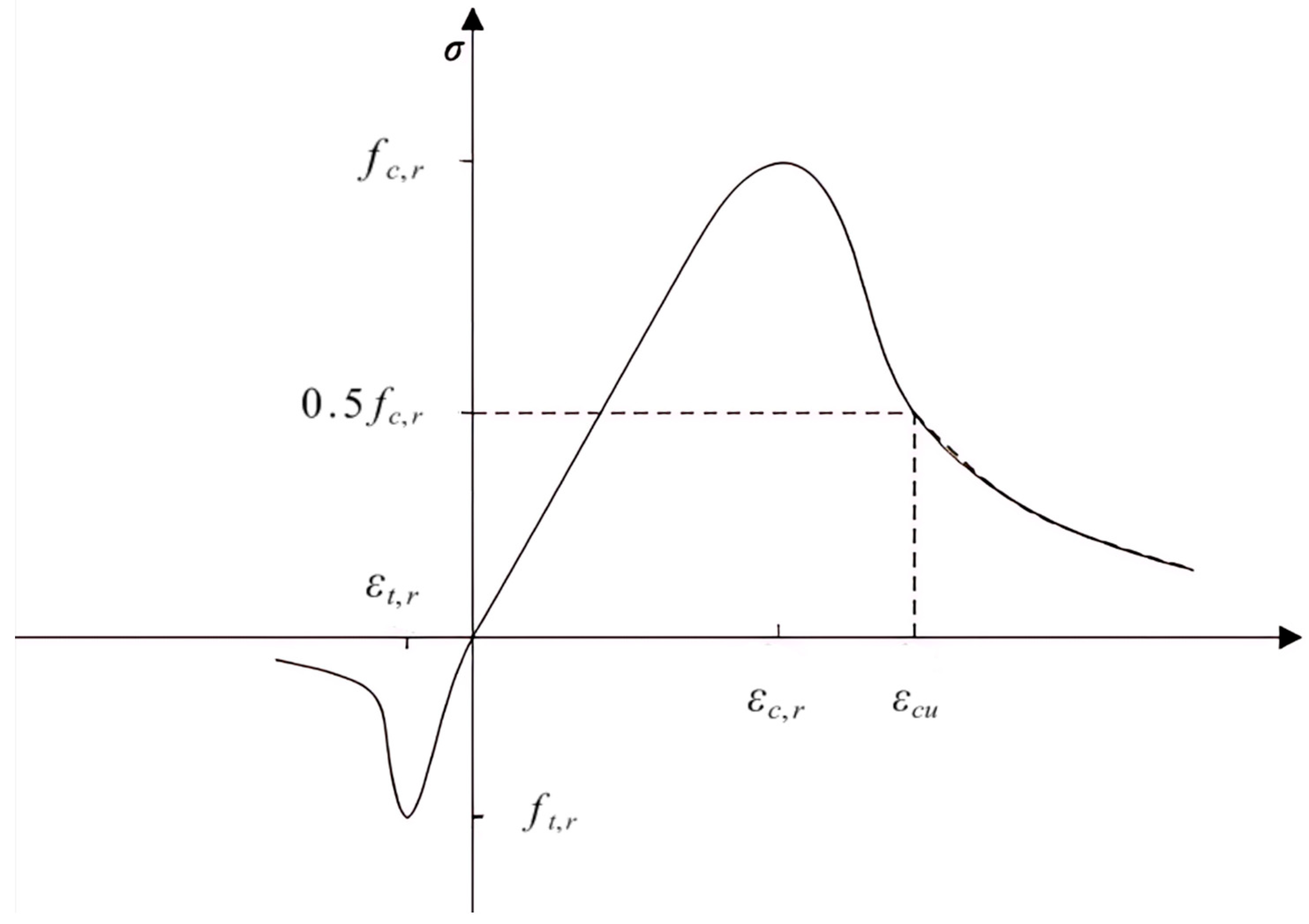
The Concrete Damaged Plasticity (CDP) model is adopted for finite element analysis. This model accounts for both tensile damage and compressive crushing of concrete and is widely used in structural simulations involving nonlinear concrete behavior. According to the Code for Design of Concrete Structures (GB 50010-2010) [19], the uniaxial stress–strain curve of concrete is presented in Figure 3.
The plastic parameters used in the finite element software are shown in Table 1.
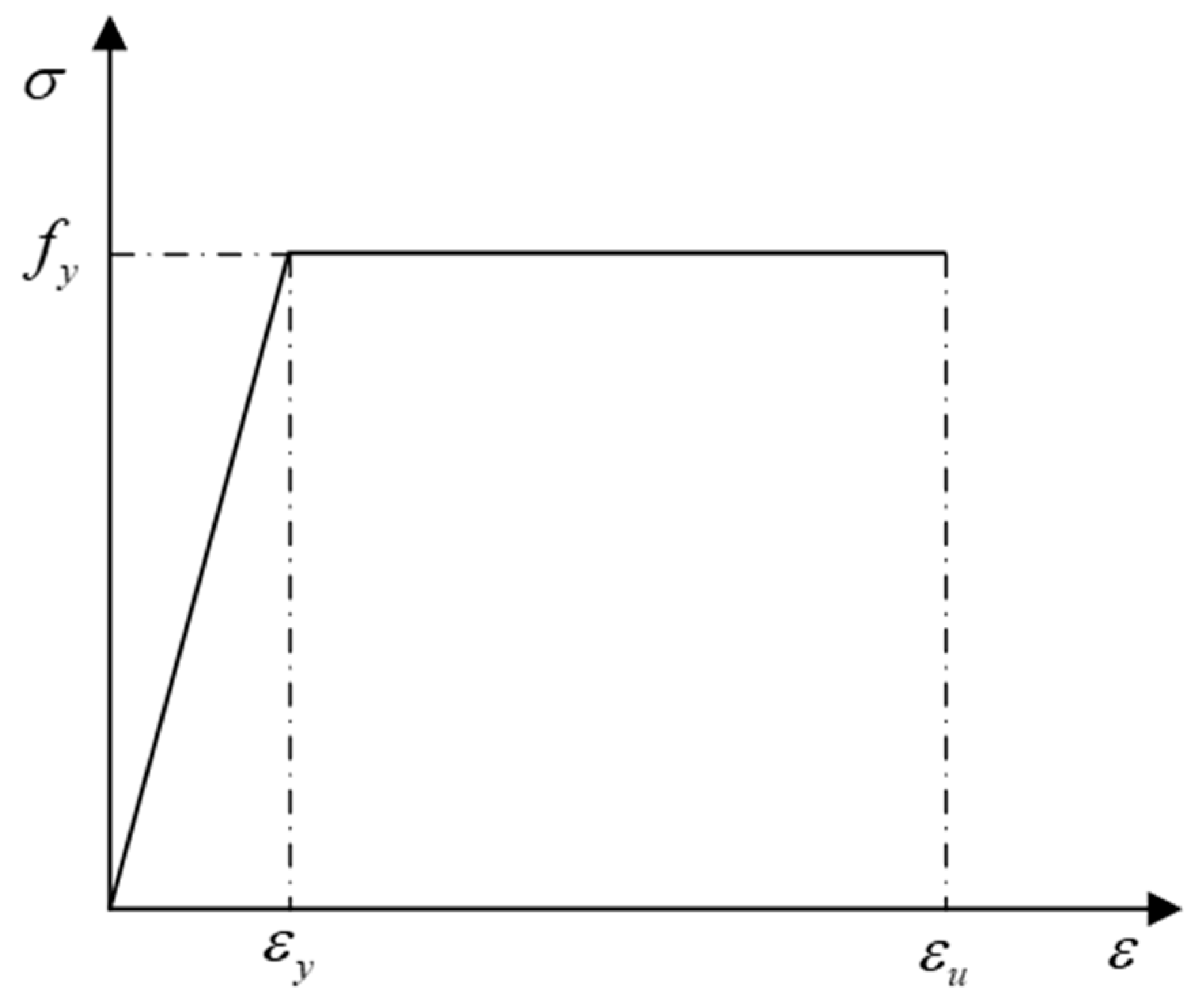
The ideal elastic–plastic model is adopted for the stud. When the stud reaches its yield strength, the stress remains constant despite further increases in strain. The corresponding constitutive relationship is illustrated in Figure 4.

3.3. Parameter Analysis

To ensure consistency in the modeling method, variations in concrete strength, composite beam section size, stirrup spacing, and shear span ratio are introduced in the finite element models. The influence of these parameters on the shear bearing capacity of the composite beam is systematically investigated.

3.3.1. Material Strength and Geometric Dimension

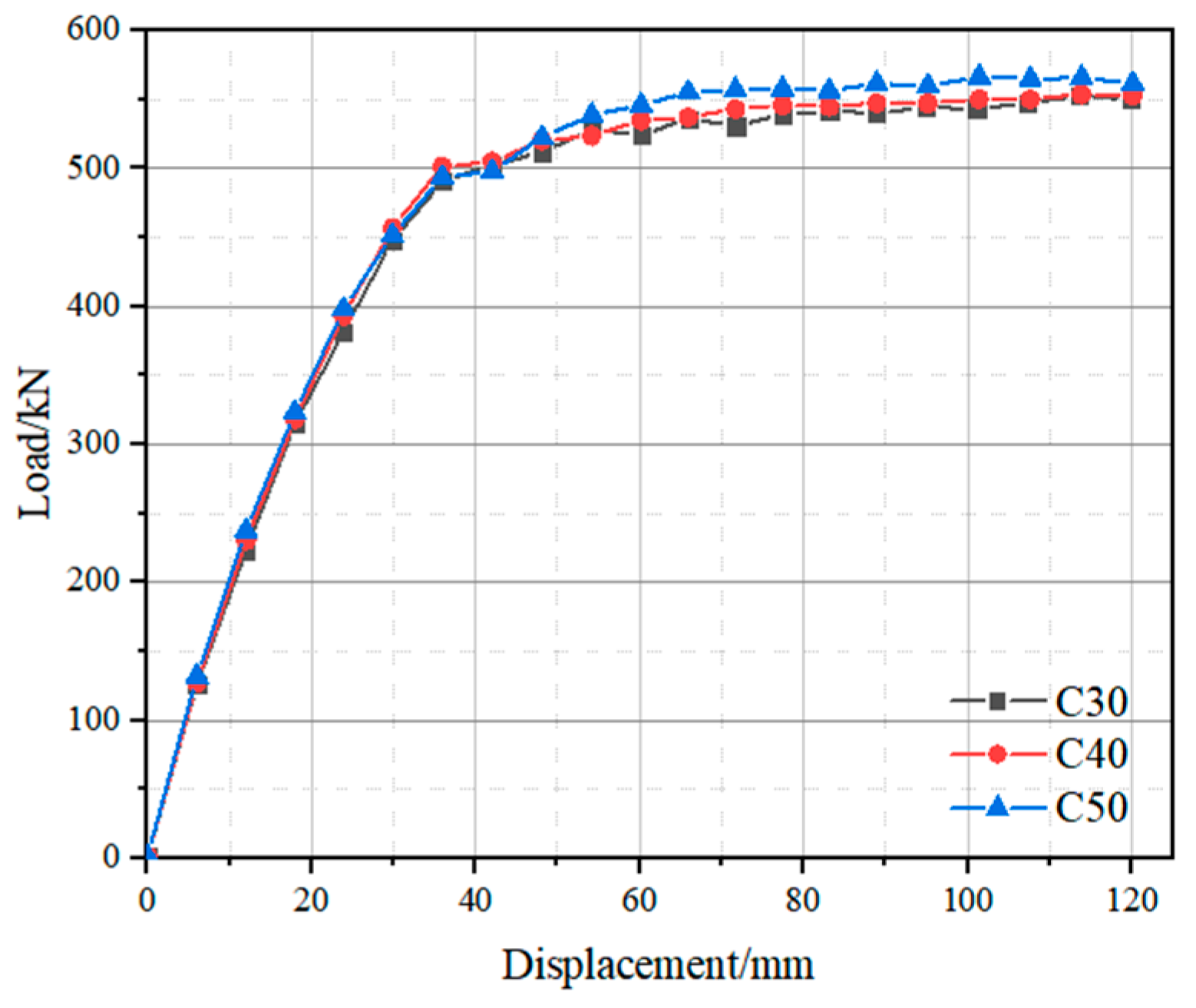
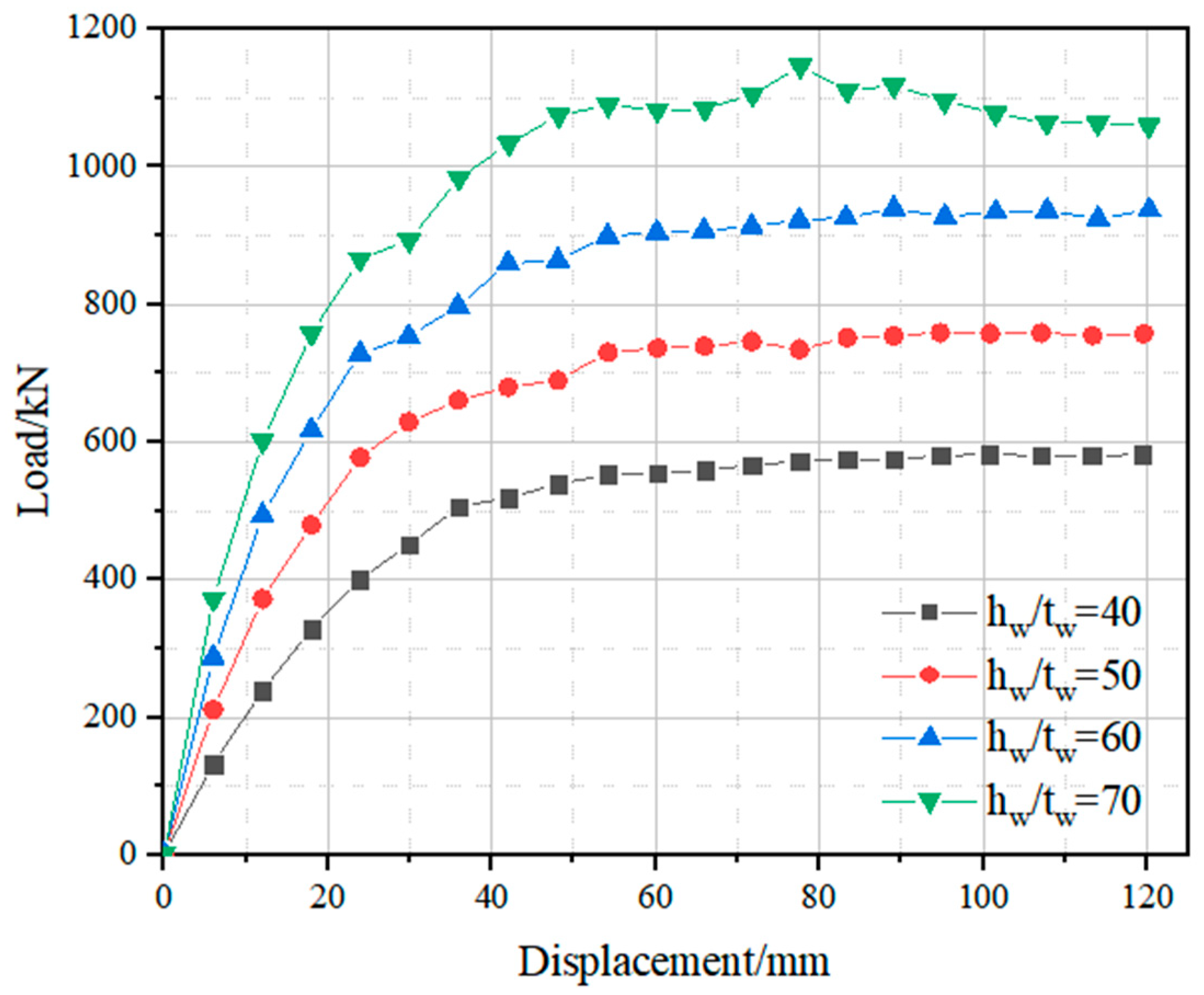
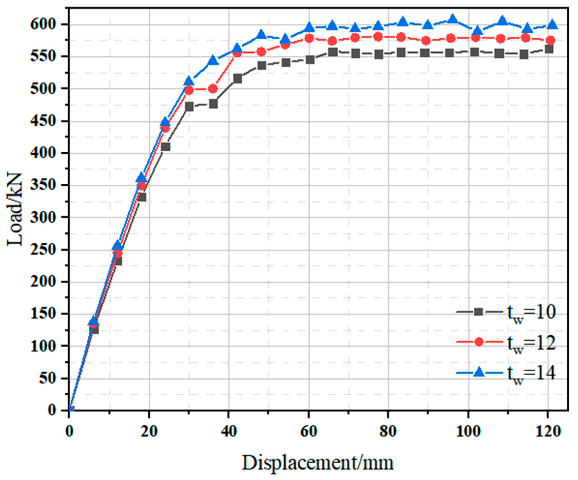
Finite element models with varying concrete strengths and composite beam section sizes were developed, and the results are presented in Figure 5, Figure 6 and Figure 7.
Figure 5 and Table 2 illustrates that the shear bearing capacity of aluminum alloy–concrete composite beams increases significantly only when high-strength concrete is utilized, with the C50 concrete showing the largest increase of 6.55%, this is because the shear resistance is mainly provided by the aluminum alloy web, while concrete contributes primarily to stability and confinement. Therefore, the effect of increasing concrete strength becomes more evident only when the concrete’s contribution approaches the aluminum web’s capacity, highlighting that concrete plays a secondary role compared to the aluminum alloy web. Figure 6 depicts the variation in load with different height-to-thickness ratios. It can be observed that as the height-to-thickness ratio of the composite beam increases, both the load and shear bearing capacity increase, with an overall growth of 25.6% when the ratio increases from 40 to 50. Figure 7 presents the variation in load with different web thicknesses. Under the given section configuration, the shear bearing capacity gradually increases with greater web thickness; however, the incremental increase between adjacent web thicknesses remains relatively small, within 2%.

3.3.2. Stirrup Spacing

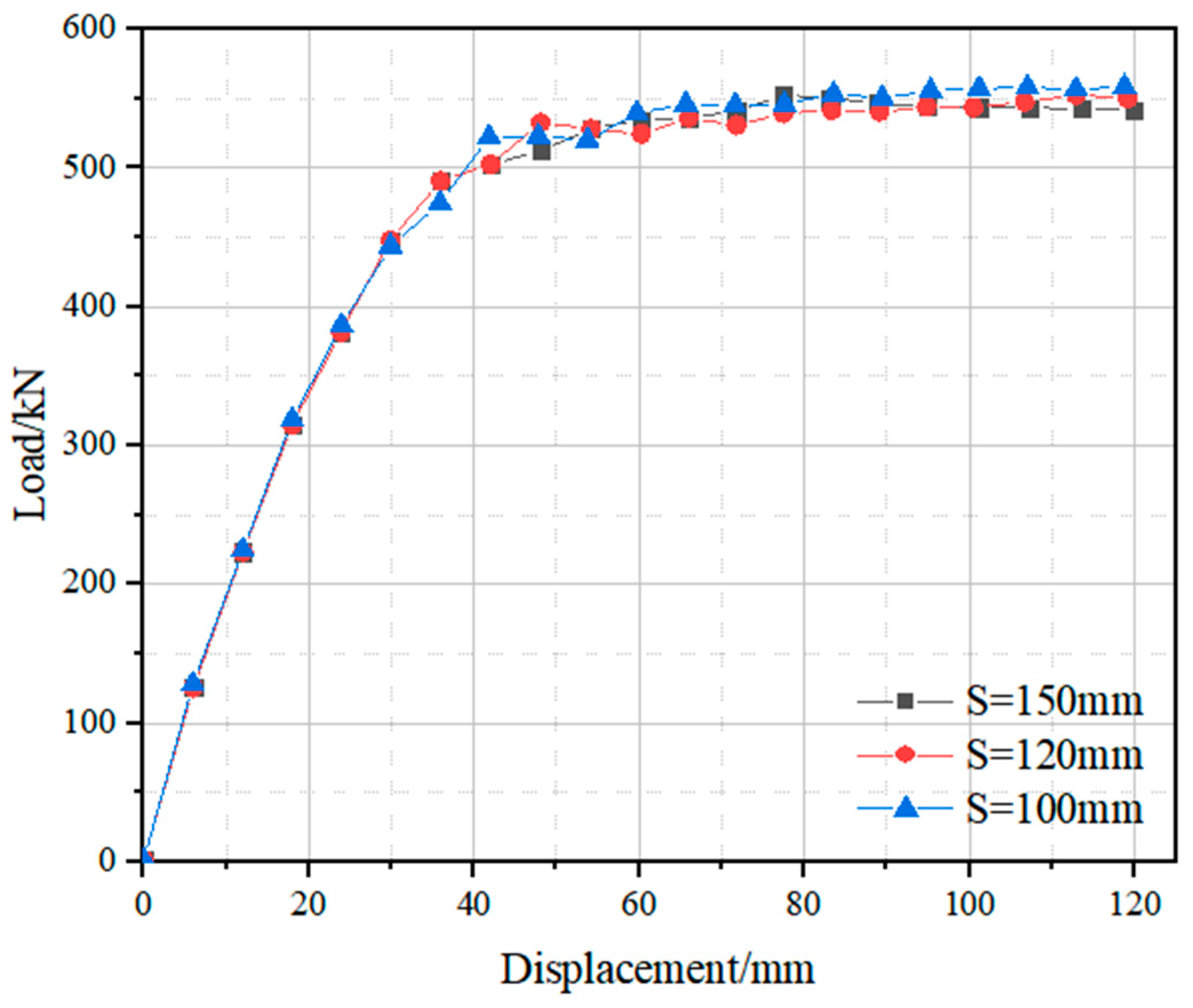
In reinforced concrete beams, stirrups are typically arranged to ensure the shear capacity of the inclined section, fully utilize the potential of the lower concrete, and constrain the concrete within the core area. Figure 8 presents a comparison of load–displacement curves for different stirrup spacings. A smaller stirrup spacing results in a greater confinement effect on the concrete enclosed by the stirrups, leading to more effective utilization of the lower concrete and an increased shear capacity of the aluminum alloy–concrete composite beam. When the stirrup spacing is reduced to 100 mm, the maximum shear capacity increases by 5.41%. In addition, reducing the stirrup spacing leads to only a modest increase in shear capacity. This is because the aluminum alloy web bears most of the shear load. While stirrups improve the confinement of the concrete and delay the development of diagonal tension cracks, their influence is secondary in the load path, especially under conditions where concrete does not reach its full shear capacity. Despite variations in stirrup spacing, the changes in peak load are minor, suggesting that stirrups mainly contribute to crack confinement rather than initial shear resistance.

3.3.3. Shear Span Ratio

The shear bearing capacity of aluminum alloy–concrete composite beams is significantly influenced by the shear span ratio. As the shear span ratio increases, the shear capacity of the beams gradually decreases due to changes in the failure mode. A total of nine finite element models with varying shear span ratios were developed, and the results are presented in Figure 9. The figure shows that when the shear span ratio increases from 1 to 3, the shear capacity decreases rapidly. However, when the shear span ratio exceeds 3, the rate of decrease slows, and shear capacity no longer plays a dominant role in the overall behavior of the beam.

4. Numerical Results and Analysis

Shear Analysis of Aluminum Alloy-Concrete Composite Beam

(1)
Stress and strain analysis of the section
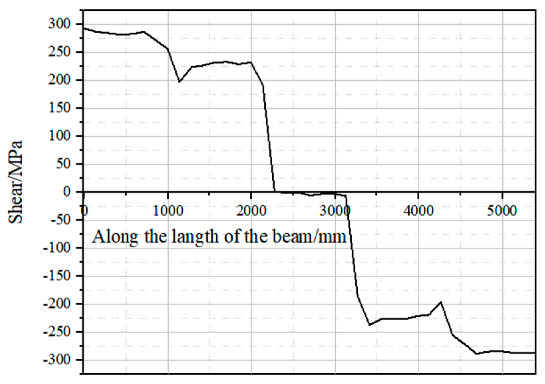
The aluminum alloy–concrete composite beam with model number ACC2-19 was selected for shear analysis. The shear distribution and shear stress distribution of the composite beam are presented as follows. Figure 10 illustrates the maximum shear force at the supports at both ends. A section of the composite beam near the support was selected, and the shear stress was extracted along four paths (Path 1 to Path 4), as shown in Figure 11.
As shown in Figure 12, the shear stress within the concrete is relatively small, with most of the shear force being carried by the aluminum alloy web. The maximum shear stress occurs at a height of 150 mm (i.e., the mid-height of the web) and is evenly distributed along the height direction. In this composite beam section, the concrete primarily serves to restrain the buckling deformation of the H-shaped aluminum alloy flange and web, thereby enhancing the overall bearing capacity.
In Figure 12 and Table 3, shear stress values along Path 1 and Path 4 are near zero because these paths are located at the outermost regions of the concrete encasement, where shear force transmission is minimal. Most of the shear is carried by the aluminum alloy web and the adjacent concrete core. This observation confirms that the contribution of edge concrete to shear resistance is negligible under the tested loading conditions. A similar conclusion was reached in a finite element study of aluminum–concrete composite beams under shear by Chen and Wang [20].
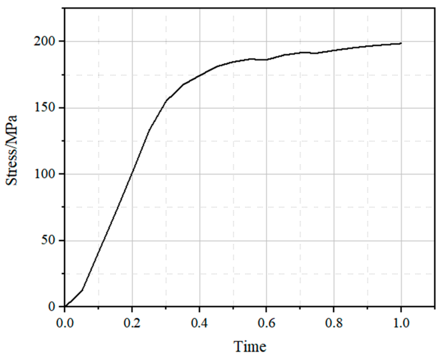
The stress–time curve of the aluminum alloy at this section was extracted, and the results are presented in Figure 13. Under loading, the stress initially increases rapidly, while the corresponding time grows slowly; subsequently, the time continues to increase while the rate of stress increase gradually decreases.
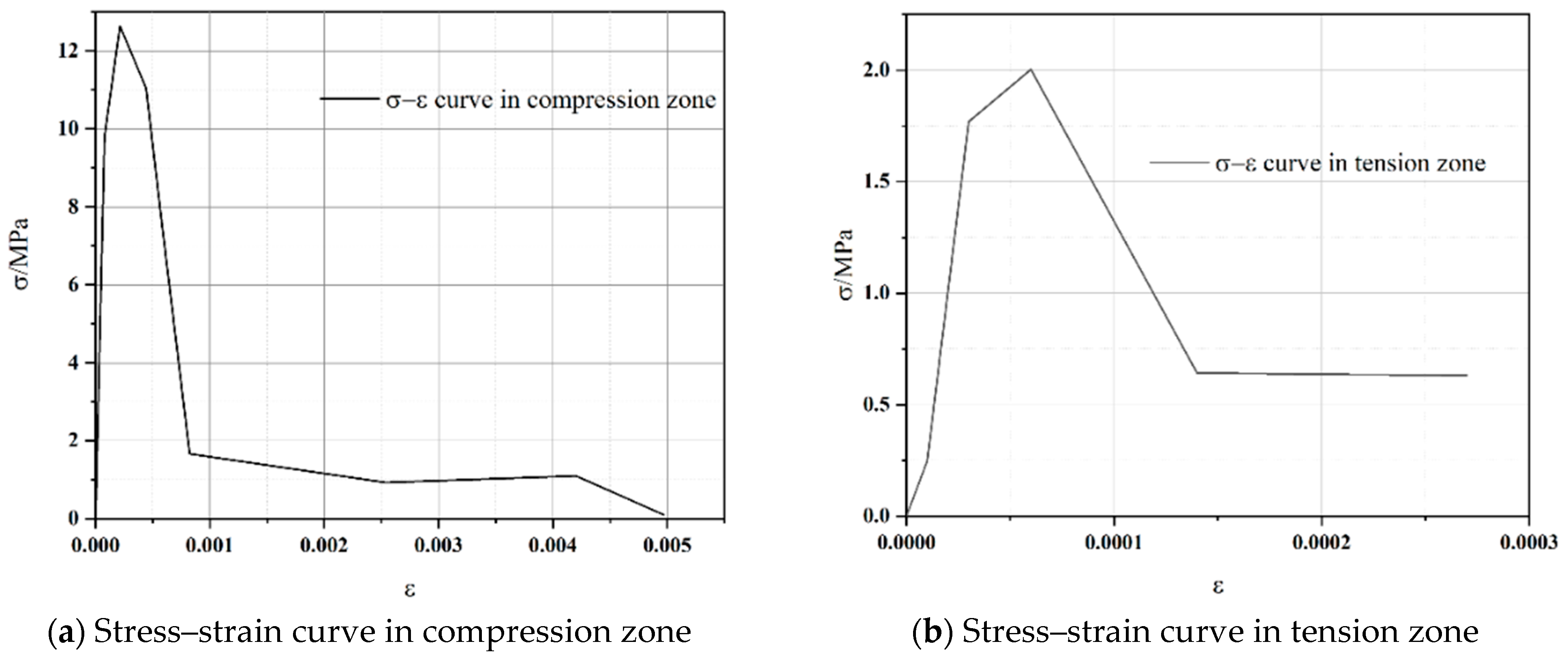
The stress–strain curve of the concrete in this section was extracted. Based on the principle of symmetry, the concrete on one side of the composite beam was selected for analysis. The stress–strain curves for the compression and tension zones of the concrete are presented in Figure 14. The results indicate that the concrete in both the compression and tension zones reaches its ultimate stress value. After reaching peak stress, although the stress decreases, plastic deformation continues to increase.
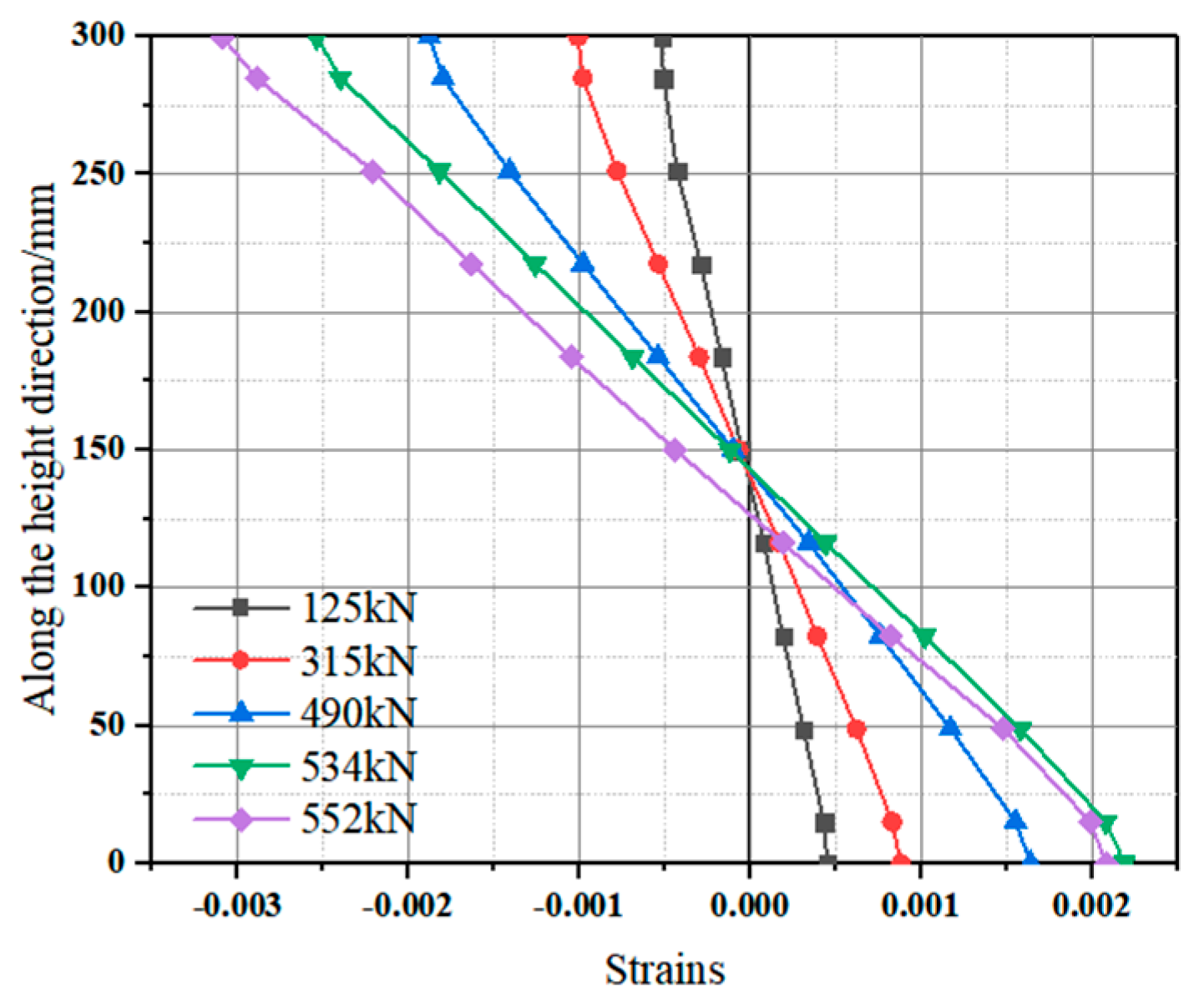
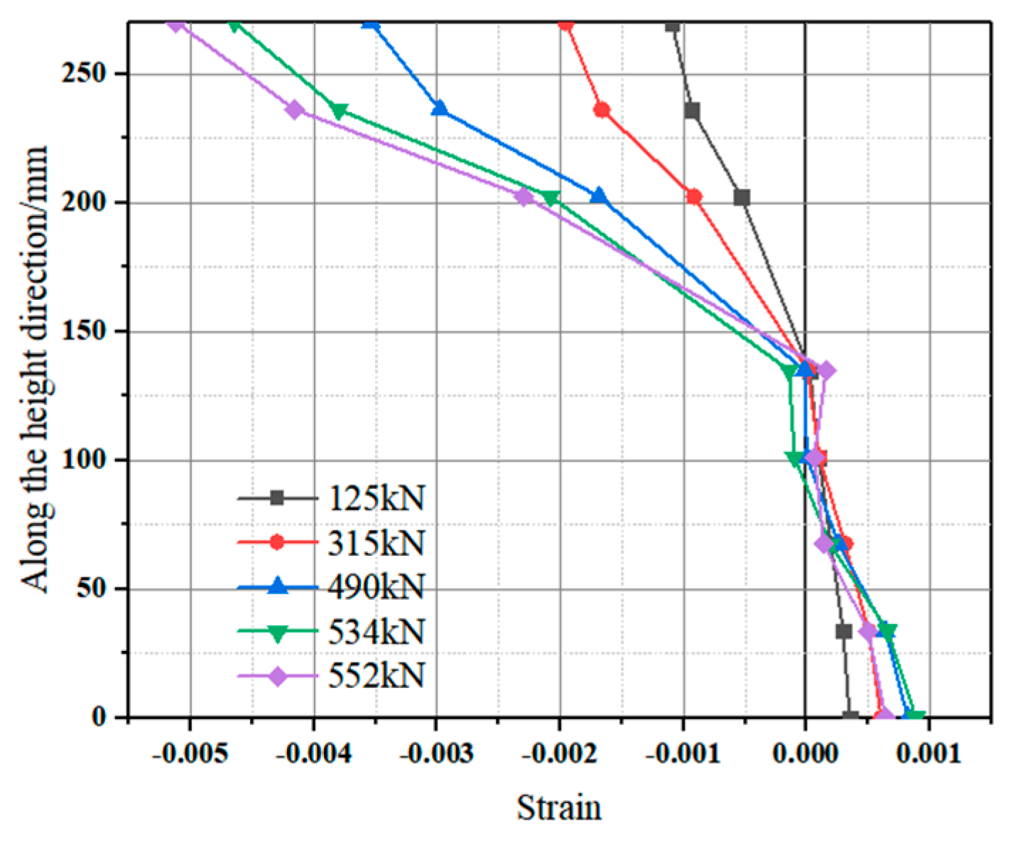
The strain data of the aluminum alloy and concrete along the height of the shear section were analyzed and organized, as shown in Figure 15 and Figure 16. The results indicate that, with increasing load, the strain in the upper part of the concrete increases significantly, while the strain in the lower part of the concrete increases slightly. When the load increases from 315 kN to 490 kN, the strain in the upper part of the concrete reaches its maximum value. When the load on the composite beam is less than the ultimate load of 552 kN, the strain values in the upper and lower flanges of the H-shaped aluminum alloy beam are nearly identical, and the position of the neutral axis remains unchanged. However, when the load reaches 552 kN, the strain in the upper flange attains its maximum value, whereas the lower flange, restrained by the studs, exhibits a lower strain. At this stage, the neutral axis shifts slightly downward, indicating that the composite beam maintains effective composite action in the shear section.
(2)
Load strain analysis
The following assumptions are made: in the aluminum alloy–concrete composite beam, the aluminum alloy structure primarily resists tensile forces, while the concrete slab mainly resists compressive forces. The shear section is selected for sectional strain analysis. The positions of six analysis points are shown in Figure 17a, and the corresponding load–strain curves are presented in Figure 17b. At the compression section, the deformation trends of the aluminum alloy and concrete are consistent; however, as the load increases, the strain in the aluminum alloy gradually decreases, and the compressive stress in the concrete exceeds that in the aluminum alloy. The aluminum alloy carries the majority of the tensile force. Due to the low tensile strength of concrete, the strain in the concrete is nearly zero.

5. Theoretical Derivation and Validation

5.1. Derivation of Shear Bearing Capacity Calculation Formula of Aluminum Alloy-Concrete Composite Beam

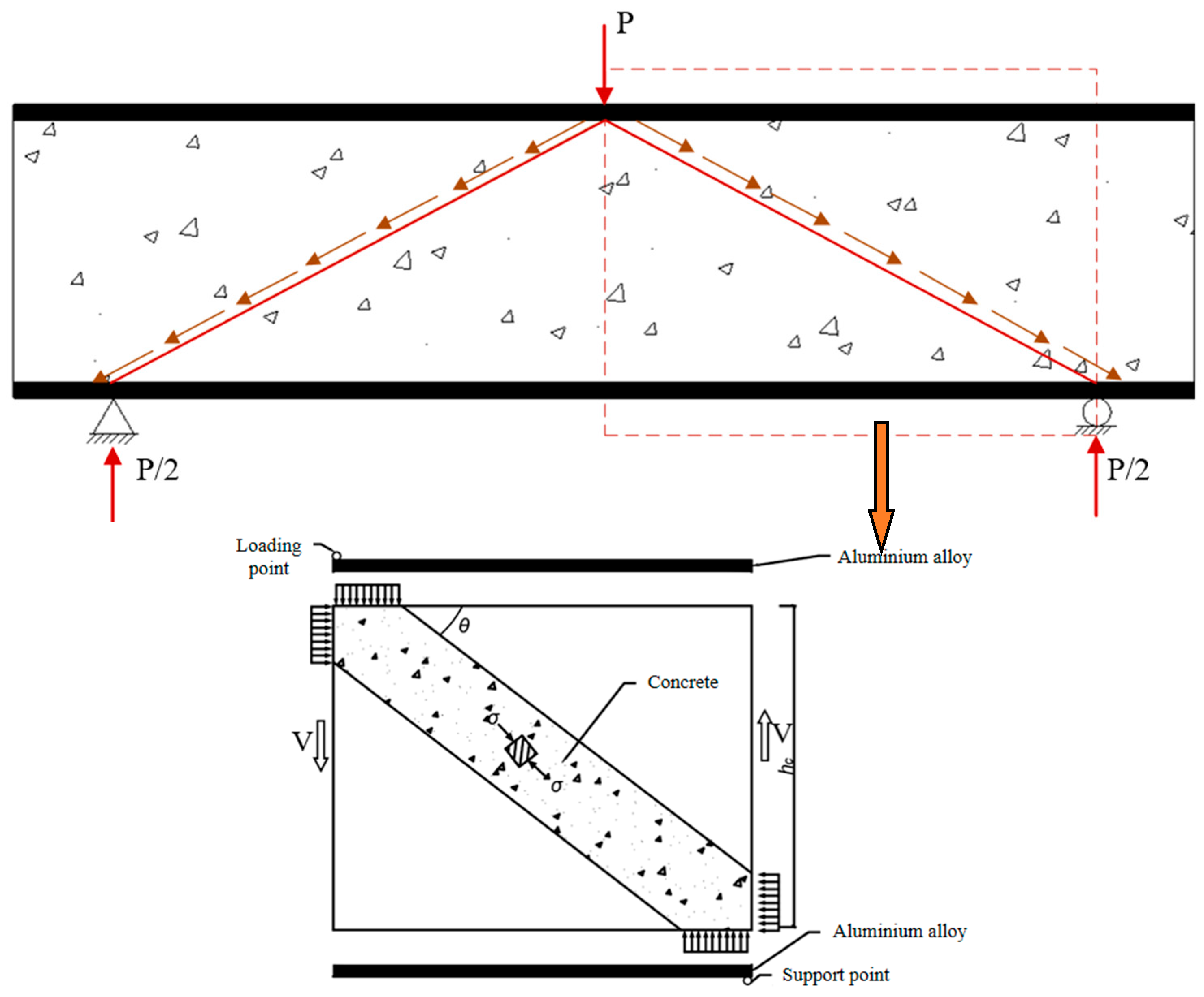
For aluminum alloy–concrete composite beams damaged by shear compression, the aluminum alloy tensile flange functions as a tie rod. The shear force carried by the abdominal concrete is transmitted through a concrete inclined block, resembling an arch. Under load, the concrete inclined block and the tensile flange form a tension–compression system. Based on the tension–compression bar model theory, Wu Kai [21] proposed an improved model in 2021, developed according to the actual stress conditions of certain encased concrete composite beams. The schematic diagram of the improved tension–compression bar model is shown in Figure 18. This improved model is applicable to the calculation of shear bearing capacity in partially encased concrete composite beams.
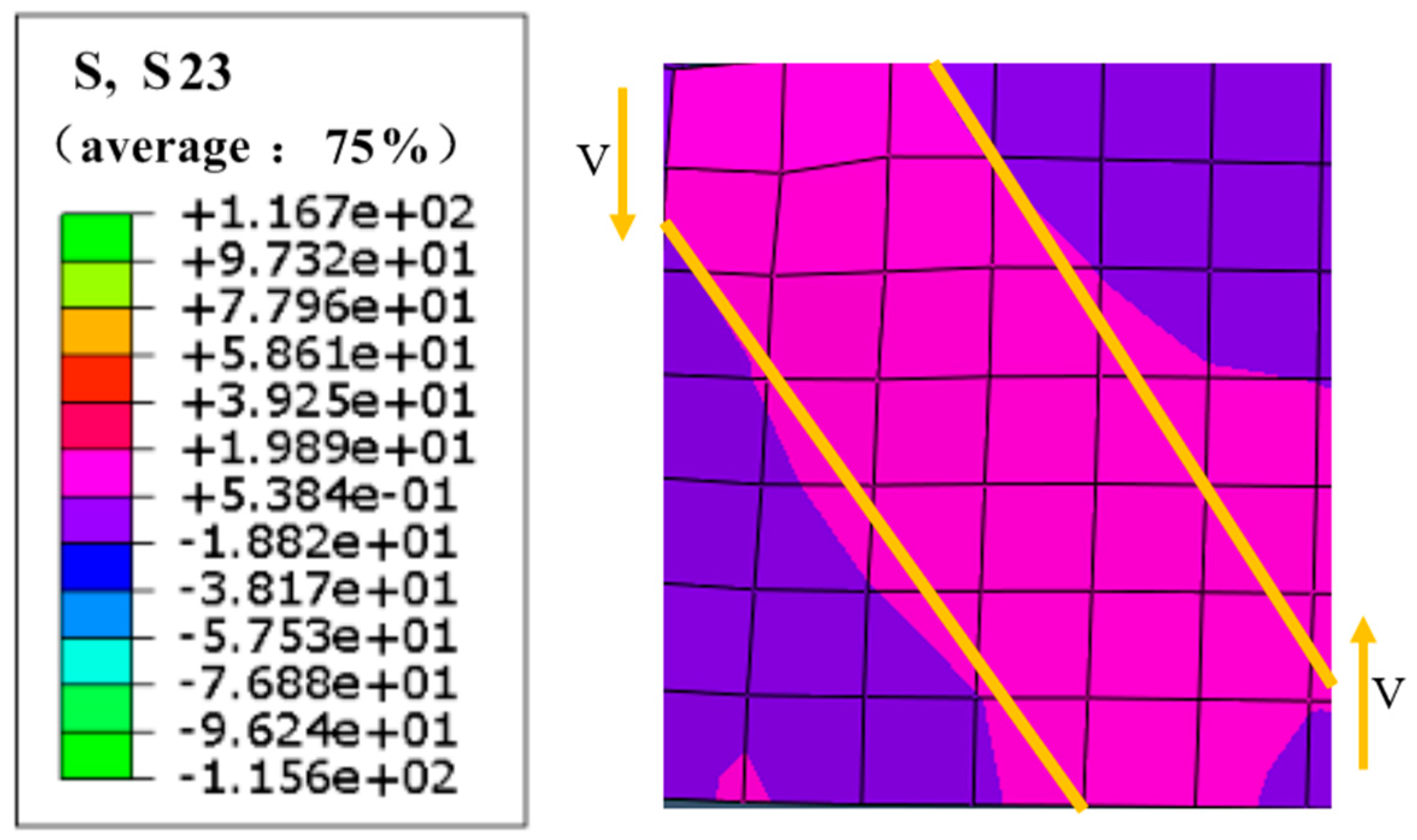
The finite element stress contour of the concrete in the shear section is shown in Figure 19. It can be observed that the deformation pattern of the improved tension–compression bar model closely corresponds with the stress distribution in the finite element analysis.

5.2. Derivation and Verification of Shear Bearing Capacity Calculation Formula of Aluminum Alloy-Concrete Composite Beam

Currently, there are no established provisions for calculating the shear bearing capacity of aluminum alloy–concrete composite beams. However, the foreign scholars Maciej Szumigała and Łukasz Polus demonstrated through experimental testing and finite element simulations that the calculation methods for steel–concrete composite beams can be applied to aluminum alloy–concrete composite beams, with an error margin of less than 5%. Therefore, the calculation of the shear bearing capacity of aluminum alloy–concrete composite beams in this study is based on the methodology used for steel–concrete composite beams.
Based on the above analysis, the shear bearing capacity of the aluminum alloy–concrete composite beam is calculated using the superposition method. In this calculation, the aluminum alloy beam considers only the shear force resisted by the web, while the contribution of the flange to the shear capacity is neglected and treated as a strength reserve. Additionally, according to Eurocode 9 [22], if the web slenderness ratio ( h w / t w ) does not satisfy the specified requirements, the shear buckling resistance of the web must be taken into account. By substituting the composite beam’s section dimensions into the verification formula, it is confirmed that the web meets the requirements. Therefore, the post-buckling strength of the web is not considered in the calculation. This is consistent with prior findings on shear buckling behavior of aluminum alloy webs [23].
In general, the superposition method is employed to calculate the shear bearing capacity of aluminum alloy–concrete composite beams, which is the sum of the shear capacities of the H-shaped aluminum alloy web, the concrete, and the stirrups. The proposed formula for calculating the shear bearing capacity of aluminum alloy–concrete composite beams is expressed as:
V = V a + V c + V v y
where V a is the shear bearing capacity of the aluminum alloy, V c is the shear bearing capacity of the concrete, and V v y is the shear bearing capacity of the stirrups.
In the absence of torsion, the previous analysis indicates that the shear stress is uniformly distributed across the aluminum alloy web. Referring to the calculation formula proposed in Eurocode 3, Part 1 [24], and considering that aluminum alloy materials do not exhibit a yield plateau, f 0.2 is adopted as the reference stress for calculation. Accordingly, the formula for calculating the shear bearing capacity of the extruded H-shaped aluminum alloy beam is expressed as follows:
V a = A v f 0.2 γ R 3
A v = A a 2 b s t f + t w + 2 r t f
where A v is the shear area; f 0.2 is the specified non-proportional strength of aluminum alloy; γ R is the partial coefficient of resistance of aluminum alloy; A a is the cross-sectional area; b s is the total width of the flange; t f is the flange thickness; t w represents the web thickness; r is the root radius.
When calculating the shear bearing capacity of the reinforced concrete in the web region, it can be divided into two components: the contribution from the concrete and that from the stirrups. Jum He [25] proposed a concrete shear strength reduction coefficient of β = 0.5 , indicating that only the concrete on one side of the web is considered in the calculation of the shear bearing capacity for partially encased steel–concrete composite beams. This approach accounts for the non-uniform distribution of oblique compressive stress along the concrete thickness direction and ensures structural safety. The calculation formula for the shear bearing capacity of stirrups refers to Eurocode 2, Part 1 [26], and is given as follows:
V v y = A s v s z f v y c o t θ
where A s v represents the cross-sectional area of stirrup; s is stirrup spacing; z is the inner rod arm, which is 0.9 times the concrete height; f v y is the design value of tensile strength of stirrup; θ is the angle between the loading point and the support.
The calculation of the shear bearing capacity of concrete is based on the above modified tension and compression bar model, and the calculation formula of the shear bearing capacity given in Eurocode 2 [26] is also referred to. The formula is as follows:
V c = b c z α C W v 1 f c c o t θ + t a n θ
where b c is the thickness of concrete; α C W is the stress state coefficient of the compression arch, and α C W is 1; v 1 is the reduction coefficient of concrete shear cracking, and v 1 is 0.6; f c is the axial compressive strength of concrete.
After sorting out the above formulas, the formula for calculating the shear bearing capacity of aluminum alloy-concrete composite beams is obtained as follows:
V = A s 2 b s t f + t w + 2 r t f f 0.2 γ R 3 + A s v s z f v y c o t θ + b c z α C W v 1 f c c o t θ + t a n θ
Substituting the data into Equation (8) yields the calculated shear bearing capacity for each model, which is compared with the corresponding finite element analysis results in Table 4.
Table 4 presents a comparison between the initial theoretical formula and FEA results across 22 models. The average ratio of calculated to simulated shear capacity is 1.173 with a standard deviation of 0.175, respectively, indicating significant error and dispersion. Due to the material property differences between aluminum alloy and steel, the formula developed for steel–concrete composite beams cannot be directly applied to aluminum alloy–concrete composite beams. Therefore, the formula requires modification.

5.3. Correction and Verification of Calculation Formula of Aluminum Alloy-Concrete Composite Beam

Since there is no transverse stiffener on the end web of the aluminum alloy beam, it is unnecessary to calculate the membrane tensile stress field after buckling. In this case, the shear bearing capacity of the composite beam only needs to account for the shear field prior to web buckling. Under loading, cracks develop in the lower portion of the concrete under tension, leading to a reduction in strength. Additionally, the presence of studs on the lower flange accelerates the propagation of these cracks. At this stage, although the web of the aluminum alloy beam has not yet reached its bearing limit, the composite beam has already failed [27,28]. Therefore, the contribution of the aluminum alloy web to shear capacity must be reduced. In 2008, Yongjiu Shi proposed that the ratio between the actual shear strength and the design shear strength value of the aluminum alloy member should be considered for H-shaped aluminum alloy webs [29]. The calculation formula for the shear capacity of the web is as follows:
V = β t w h w f v
where β is the strength reduction coefficient, the ratio of the actual shear strength to the design value of the shear strength; t w is the web thickness, h w is the web height; f v is the design value of shear strength.
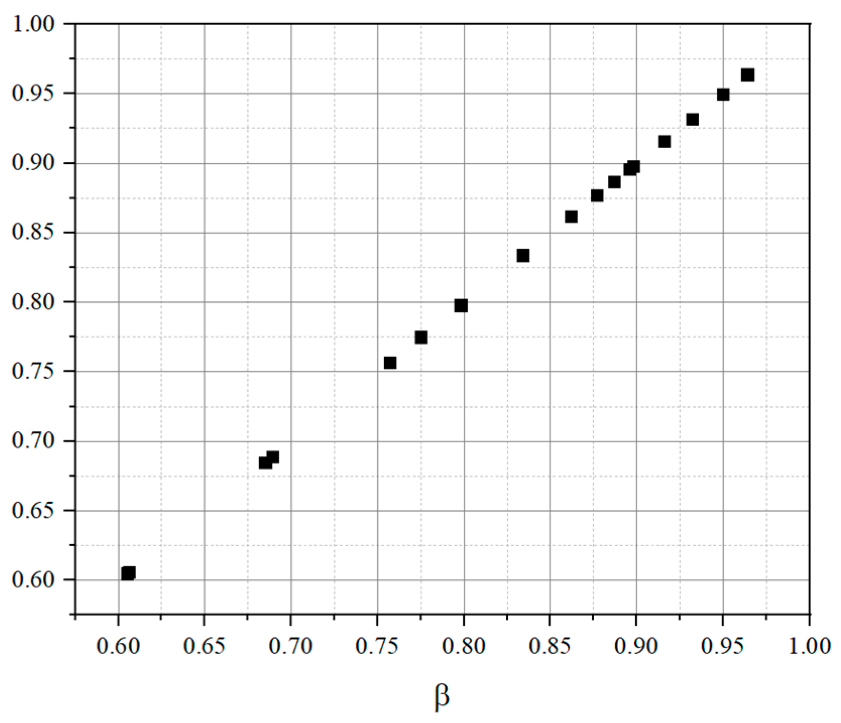
A total of 22 finite element models were developed for the parametric analysis, and the corresponding values of β were extracted and calculated, as shown in Figure 20. The average value of β was used in the calculation. Accordingly, the shear bearing capacity of the partially encased concrete composite beams was determined as follows:
V = β f 0.2 A s 2 b s t f + t w + 2 r t f γ R 3 + A s v z f v y c o t θ s + b c z α C W v 1 f c c o t θ + t a n θ
Table 5 shows the results using the modified formula that includes a strength reduction coefficient. The average ratio improves to 1.018 with a reduced standard deviation of 0.151, confirming that the corrected formula provides a much better fit to the FEA results and significantly reduces error dispersion. Notably, three models exhibit significantly lower Vcal/VFEA ratios (below 0.82), indicating that the proposed formula overestimates shear capacity under these specific conditions. These cases correspond to extreme shear span ratios and geometric configurations where local effects and strain incompatibility likely reduce the contribution of stirrups or concrete. These deviations suggest that the proposed formula may require caution or additional calibration when applied outside the tested parameter range. This limitation is further discussed in Section 6.1.
As shown in Figure 21, except for the finite element model with a shear span ratio of 1.5, the other data points are generally close to V c a l / V F E A . This result verifies the rationality and feasibility of the proposed formula for calculating the shear capacity of aluminum alloy–concrete composite beams based on the improved strut-and-tie model.
Compared to empirical or simplified methods used for steel–concrete composite beams, the proposed formula accounts for the distinct material properties of aluminum alloy and the combined shear contribution of web, concrete, and stirrups. It is derived based on a physically justified mechanical model (tension–compression bar theory) and calibrated through finite element analysis. This allows for improved accuracy and adaptability to varying parameters, including web thickness and shear span ratio, which are often overlooked in traditional models. Unlike purely empirical expressions, the method maintains a balance between simplicity and physical insight, making it practical for design yet grounded in mechanics.

6. Discussion and Limitations

6.1. Limitations

This study has several limitations that should be considered when applying the proposed shear capacity formula in practical engineering design:
(1)
Post-buckling behavior of the aluminum alloy web is not included in the finite element model or theoretical derivation. The model only considers pre-buckling shear resistance, which may underestimate or overestimate capacity in slender web sections.
(2)
Perfect bonding is assumed between the aluminum alloy and the concrete interface. No slip, debonding, or relative movement is modeled, which may affect accuracy in real composite structures with incomplete connections or interface degradation.
(3)
Flange contribution to shear resistance is neglected. The flanges are treated as axial force components, while their potential shear capacity is considered a strength reserve and not quantified in this model.
(4)
Material model simplifications: The concrete is modeled using the Concrete Damaged Plasticity (CDP) model without considering long-term effects such as creep or shrinkage.
(5)
Parameter range limitations: The formula is verified only for shear span ratios between 1.0 and 5.0, concrete grades between C30 and C50, and the specific geometric configuration studied. Application outside this range requires further verification.
(6)
No experimental validation has been conducted. All verification is based on finite element simulations. While a strong correlation with FEA results is shown, real-world factors may introduce additional variability.
These limitations highlight that while the proposed method is reliable within the tested range, engineers and researchers should carefully assess applicability for atypical geometries, material combinations, or loading conditions.

6.2. Practical Applications

The proposed shear capacity formula can be directly applied in the preliminary and detailed design of aluminum alloy–concrete composite beams, particularly in environments requiring high corrosion resistance, such as marine platforms, offshore wind turbine foundations, and coastal bridges. The model offers a simplified yet accurate method for estimating shear strength without the need for complex nonlinear simulations, thus supporting efficient structural optimization and material selection in engineering practice.

7. Conclusions

In this study, a finite element model of an aluminum alloy–concrete composite beam was developed and analyzed, and a calculation formula for its shear bearing capacity was proposed. The main conclusions are as follows:
(1)
The shear bearing capacity increases by a maximum of 6.55% with higher concrete strength. It also increases by up to 25.6% and 7.45% with a greater web height-to-thickness ratio and web thickness, respectively. An increase in bolt diameter results in a maximum shear capacity increase of 2.6%. Reducing stirrup spacing leads to a maximum increase of 5.41% in shear capacity. As the shear span ratio increases from 1 to 3, the shear bearing capacity of aluminum alloy–concrete composite (ACC) beams decreases; when the shear span ratio exceeds 3, the rate of decrease slows.
(2)
A calculation formula for the shear bearing capacity of aluminum alloy–concrete composite beams was established using the superposition method. The total shear capacity primarily comprises contributions from the aluminum alloy beam web, concrete, and stirrups. Comparison of the formula results with finite element analysis (FEA) values showed a relatively large initial error. After introducing a strength reduction coefficient for correction, the final average ratio of the formula solution to the FEA value was 1.018, with a standard deviation of 0.151, indicating low dispersion and improved accuracy of the formula and the proposed formula was validated against 22 FEA models, demonstrating excellent agreement with numerical results and confirming its reliability for practical engineering applications.
(3)
This study addresses a key gap in the current literature: the lack of a validated shear capacity formula tailored specifically for aluminum alloy–concrete composite beams. By developing and verifying a new theoretical model based on an improved tension–compression bar mechanism and supporting it with finite element analysis, the research contributes both methodologically and practically. The proposed formula enables more accurate and material-specific shear capacity assessment, facilitating the application of aluminum–concrete composite structures in environments where corrosion resistance is critical. Future research may expand on this work through experimental validation and extension to dynamic or fatigue loading scenarios. Furthermore, recent advances such as the application of engineered cementitious composites [30,31,32], optimization of shear behavior in hybrid and corrugated systems [33,34], and the use of intelligent design methods like morphable components and machine-learning-based multiscale modeling [35,36] provide promising directions for further refinement and application of aluminum–concrete composite structures.

Author Contributions

Writing—original draft, conceptualization, data curation, visualization, C.L.; conceptualization, data curation, writing—review, supervision, and editing, software acquisition, Z.L. All authors have read and agreed to the published version of the manuscript.

Funding

This research was supported by the Natural Science Foundation of Shaanxi Province, No. S2024-JC-QN-1462 and 2023-JC-QN-0479.

Data Availability Statement

The original contributions presented in this study are included in the article. Further inquiries can be directed to the corresponding author.

Acknowledgments

The authors thank the Natural Science Foundation of Shaanxi Province for supporting this research.

Conflicts of Interest

The authors declare no conflicts of interest.

References

  1. Shi, Y.J.; Cheng, M.; Wang, Y.Q. Application and study of aluminum alloy in building structures. Build. Sci. 2005, 21, 7–11+20. [Google Scholar]
  2. Yang, L.P.; Wei, S.; Zhang, Q.L. Aluminum reticulated spatial structures: State of the art and key issues. J. Build. Struct. 2013, 34, 1–19+60. [Google Scholar]
  3. Yang, F.Q. Closed-loop recycling boosts the leapfrog development of the secondary aluminum industry. Resour. Recycl. 2020, 18–21. (In Chinese) [Google Scholar]
  4. Siwowski, T. Test and Finite Element Analysis of an ‘Aluminium-Lightweight Concrete’ Composite Girder. Struct. Eng. Int. 2006, 16, 319–325. [Google Scholar] [CrossRef]
  5. Polus, Ł.; Szumigała, M. A Numerical Analysis of the Resistance and Stiffness of the Aluminium and Concrete Composite Beam. Civ. Environ. Eng. Rep. 2014, 15, 99–112. [Google Scholar] [CrossRef]
  6. Polus, Ł.; Szumigała, M. Tests of shear connectors used in aluminium-concrete composite structures. In Recent Progress in Steel and Composite Structures—Proceedings of the 13th International Conference on Metal Structures, Zielona Góra, Poland, 15–17 June 2016; ICMS: Sydney, Australia, 2014. [Google Scholar]
  7. Szumigała, M.; Polus, Ł. An Numerical Simulation of an Aluminium-concrete Beam. Procedia Eng. 2017, 172, 1086–1092. [Google Scholar] [CrossRef]
  8. Polus, Ł.; Szumigała, M. Theoretical and Numerical Analyses of an Aluminium-Concrete Composite Beam with Channel Shear Connectors. Eng. Trans. 2019, 57, 535–556. [Google Scholar]
  9. Polus, Ł.; Szumigała, M. An experimental and numerical study of aluminium–concrete joints and composite beams. Arch. Civ. Mech. Eng. 2019, 19, 375–390. [Google Scholar] [CrossRef]
  10. Eurocode 4; Design of Composite Steel and Concrete Structures: Part 1.1: General Rules and Rules for Buildings. European Committee for Standardization: Brussels, Belgium, 2004.
  11. AISI S100; North American Specification for the Design of Cold-Formed Steel Structural Members. American Iron and Steel Institute: Washington, DC, USA, 2012.
  12. Gong, W.Z. Experimental Study on Flexural Behavior of Concrete Filled Aluminum Alloy Tube. Ph.D. Dissertation, Hua Qiao University, Quanzhou, China, 2016. [Google Scholar]
  13. Xing, G.H.; Luo, X.B.; Jun, M.; Zhang, W.L.; Chen, R.X.; Li, J.H.; Deng, Y.L.; Wang, T.; Sun, K.; Ma, L. Study on bonding performance and debonding capacity of RC beam strengthened with NSM aluminum alloy bars. J. Archit. Civ. Eng. 2021, 38, 41–50. (In Chinese) [Google Scholar]
  14. Zhang, Y.T. Study on Bond Properties Between Aluminum Alloy and Concrete. Ph.D. Dissertation, Chang’an University, Xi’an, China, 2015. [Google Scholar]
  15. Badawi, M.; Abdelmgeed, F.A.; Elsamak, G.; Alharthai, M.; Bahrami, A.; Ghalla, M. Numerical study on enhancing shear performance of RC beams with external aluminum alloy plates bonded using steel anchors. Results Eng. 2024, 22, 102143. [Google Scholar]
  16. Hu, T.; Zeng, X.; Liu, H.B.; Zhang, Y.; Li, S.; Ma, K.; Xu, J.; Wang, R.; Zhao, L.; Chen, H.; et al. Review on aluminum alloy–concrete composite structure research progress. Concrete 2020, 5, 5–8. (In Chinese) [Google Scholar]
  17. Ramberg, W.; Osgood, W.R. Description of Stress-Strain Curves by Three Parameters; NACA TN-902: Washington, DC, USA, 1943. [Google Scholar]
  18. Steinhardt, O. Aluminum constructions in civil engineering. Aluminum 1971, 47, 131–139. [Google Scholar]
  19. GB 50017-2017; Code for Design of Concrete Structures. Architecture and Architecture Press: Beijing, China, 2018.
  20. Chen, Y.; Wang, J. Finite element analysis and design recommendations for aluminum alloy–concrete composite beams under shear. Thin-Walled Struct. 2023, 182, 110245. [Google Scholar]
  21. Wu, K.; Lin, S.; Liu, X.; Mao, F.; Tan, C. Experimental Study on Load Bearing Capacity of Prefabricated Partially Encased Composite Beams. Int. J. Struct. Stab. Dyn. 2021, 21, 2150104. [Google Scholar] [CrossRef]
  22. BS EN 1999-1-1:2007; Eurocode 9 (EC9): Design of Aluminium Structures, Part 1-1: General Structural Rules—General Structural Rules and Rules for Buildings. European Committee for Standarization (CEN): Brussels, Belgium, 2007.
  23. Shi, Q.J.; Cheng, M.; Wang, Y.Q. Shear buckling design of webs in aluminum beams. J. Tsinghua Univ. (Sci. Technol.) 2008, 2008, 918–921. [Google Scholar]
  24. Eurocode 3; Design of Steel Structures: Part 1.1: General Rules and Rules for Buildings. European Committee for Standardization: Brussels, Belgium, 2005.
  25. He, J.; Liu, Y.Q.; Chen, A.R.; Yoda, T. Shear behavior of partially encased composite I-girder with corrugated steel web: Experimental study. J. Constr. Steel 2012, 77, 193–209. [Google Scholar] [CrossRef]
  26. Eurocode 2; Design of Concrete Structures: Part 1.1: General Rules and Rules for Buildings. European Committee for Standardization: Brussels, Belgium, 2004.
  27. Zhou, F.; Young, B. Shear buckling resistance of aluminum alloy beams: Experimental tests and reliability analysis. J. Struct. Eng. (ASCE) 2023, 149, 04022259. [Google Scholar]
  28. Wang, Y.; Shi, Y. Post-buckling behavior of aluminum alloy beams under shear: Numerical and analytical studies. Thin-Walled Struct. 2020, 157, 107083. [Google Scholar]
  29. Yuan, L.; Zhang, Q.L.; Luo, X.Q.; Ouyang, Y.; Yin, J. Shear resistance of aluminum alloy extruded H-Section beams. Thin-Walled Struct. 2020, 159, 107279. [Google Scholar] [CrossRef]
  30. Mo, C.; Huang, J.; Huang, J.; Tan, J. Finite element analysis on flexural performance of the bending capacity for concrete beams reinforced with ECC and aluminum alloy bars. Highlights Sci. Eng. Technol. 2023, 62, 22–30. [Google Scholar] [CrossRef]
  31. Cheng, K.; Du, Y.; Wang, H.; Liu, R.; Sun, Y.; Lu, Z.; Chen, L. Experimental Study of the Shear Performance of Combined Concrete–ECC Beams without Web Reinforcement. Materials 2023, 16, 5706. [Google Scholar] [CrossRef] [PubMed]
  32. Maheswaran, J.; Chellapandian, M.; Sivasubramanian, M.V.; Murali, G.; Vatin, N.I. Experimental and Numerical Investigation on the Shear Behavior of Engineered Cementitious Composite Beams with Hybrid Fibers. Materials 2022, 15, 5059. [Google Scholar] [CrossRef] [PubMed]
  33. Sharaky, I.A.; Alharthi, Y.M.; Elamary, A.S. Effect of Shear and Pure Bending Spans on the Behaviour of Steel Beams with Corrugated Webs. Materials 2022, 15, 4675. [Google Scholar] [CrossRef] [PubMed]
  34. Xiong, Z.; Li, J.; Mou, X.; Wang, T.; Baktheer, A.; Feldmann, M. Experimental and Theoretical Study of Thin-covered Composite Dowels considering Multiple Load Conditions. arXiv 2025, arXiv:2502.18956. [Google Scholar] [CrossRef]
  35. Huo, W.; Liu, C.; Liu, Y.; Du, Z.; Zhang, W.; Guo, X. A novel explicit design method for complex thin-walled structures based on embedded solid moving morphable components. arXiv 2023, arXiv:2306.10449. [Google Scholar] [CrossRef]
  36. Wei, H.; Wu, C.T.; Hu, W.; Su, T.H.; Oura, H.; Nishi, M.; Naito, T.; Chung, S.; Shen, L. LS-DYNA Machine Learning-based Multiscale Method for Nonlinear Modeling of Short Fiber-Reinforced Composites. arXiv 2023, arXiv:2301.02738. [Google Scholar] [CrossRef]
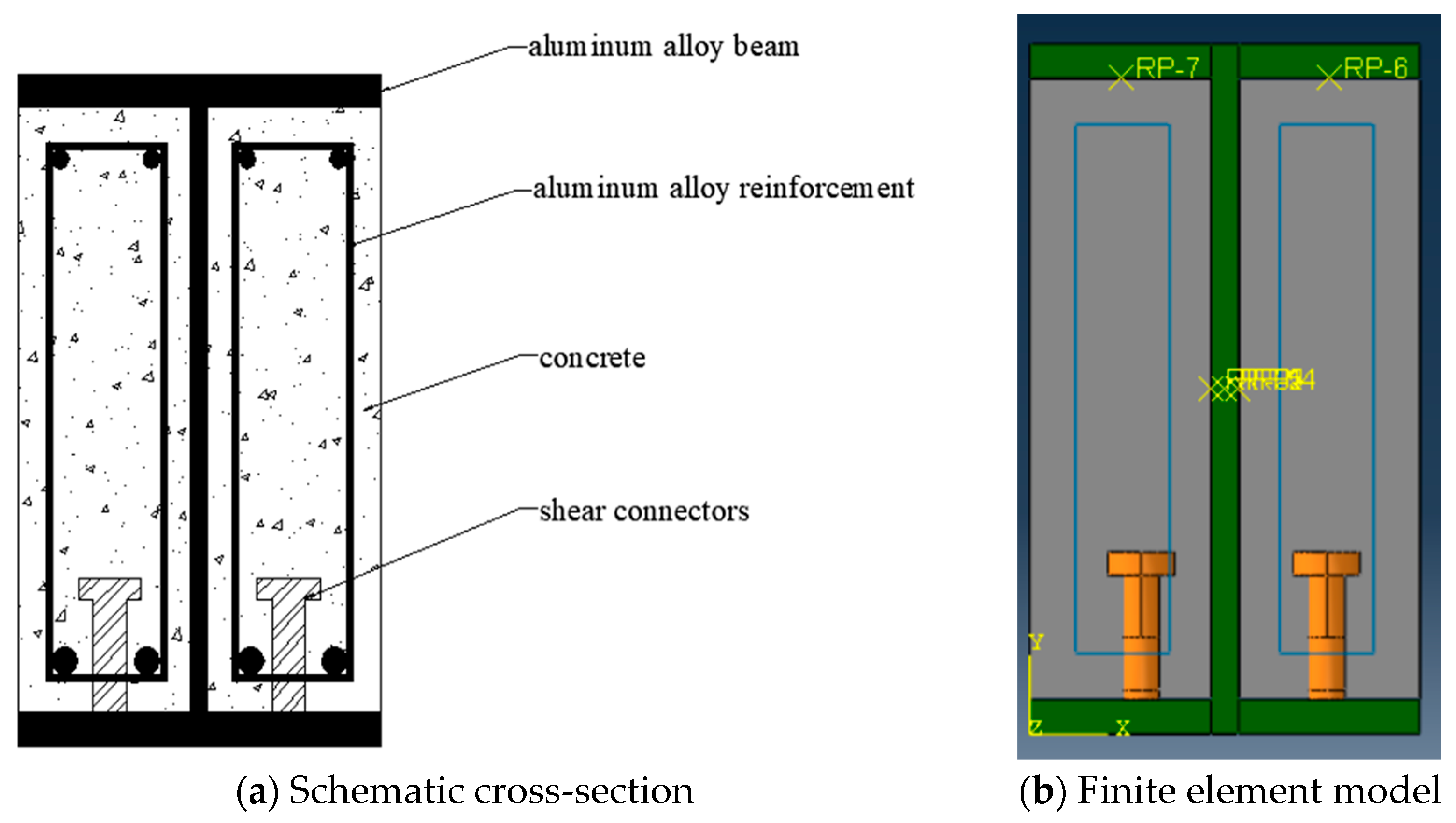
Figure 1. Section and finite element model of aluminum alloy–concrete composite beam.
Buildings 15 02393 g001
Figure 2. Stress–strain curve of aluminum alloy 6061-T6.
Buildings 15 02393 g002
Figure 3. Uniaxial stress–strain curve of concrete.
Buildings 15 02393 g003
Figure 4. Constitutive model of stud.
Buildings 15 02393 g004
Figure 5. Comparison of load–displacement curves under different concrete strengths.
Buildings 15 02393 g005
Figure 6. Comparison of load–displacement curves under different height–thickness ratios.
Buildings 15 02393 g006
Figure 7. Comparison of load–displacement curves under different web thicknesses.
Buildings 15 02393 g007
Figure 8. Comparison of load–displacement curves under different stirrup spacing.
Buildings 15 02393 g008
Figure 9. Curve of load-shear span ratio variation under the same span.
Buildings 15 02393 g009
Figure 10. Shear distribution diagram of aluminum alloy–concrete composite beam.
Buildings 15 02393 g010
Figure 11. Path distribution.
Buildings 15 02393 g011
Figure 12. The shear stress distribution of the composite beam section along the height direction.
Buildings 15 02393 g012
Figure 13. Stress-time curve of aluminum alloy.
Buildings 15 02393 g013
Figure 14. Stress–strain curve of concrete.
Buildings 15 02393 g014
Figure 15. The aluminum alloy part strains along the height direction.
Buildings 15 02393 g015
Figure 16. The concrete part strains along the height direction.
Buildings 15 02393 g016
Figure 17. Strain on a section of the composite beam.
Buildings 15 02393 g017
Figure 18. Schematic diagram of the improved tension and compression bar model.
Buildings 15 02393 g018
Figure 19. Partial stress cloud of concrete.
Buildings 15 02393 g019
Figure 20. Strength reduction factor.
Buildings 15 02393 g020
Figure 21. Comparison of calculation results of shear capacity.
Buildings 15 02393 g021
Table 1. Plastic parameters of the concrete damage model.
Dilation AngleEccentricity f b 0 / f c 0 kViscosity Parameter
300.11.160.66671 × 10−5
Table 2. The load capacity values and percentage increases for each concrete strength grade.
Concrete GradePeak Load
(kN)
Shear Capacity (kN)Increase
(%)
C30264.00281.18
C40272.00288.20+2.49%
C50299.40299.60+6.55%
Table 3. Path peak shear stress.
Path No.LocationPeak Shear Stress (MPa)
Path 1Outer concrete edge~0.00
Path 2Near web (left side)3.25
Path 3Near web (right side)4.10
Path 4Outer concrete edge~0.00
Table 4. Comparison between finite element value and the formula value of the aluminum alloy-concrete composite beam.
Model Number f c
(MPa)
λ h w
(mm)
t w
(mm)
t f
(mm)
b c
(mm)
d
(mm)
s
(mm)
V F E A
(MPa)
V c a l
(MPa)
V c a l V F E A
ACC2-114.33.62708158116150281.18344.981.227
ACC2-219.13.62708158116150288.20359.601.248
ACC2-323.13.62708158116150299.60371.781.241
ACC2-414.33.63208158116150318.40367.271.182
ACC2-514.33.64008158116150400.00456.421.162
ACC2-614.33.64808158116150477.10545.571.167
ACC2-714.33.65608158116150564.80634.721.169
ACC2-814.33.627010158116150291.70348.131.193
ACC2-914.33.627012158116150295.60351.281.188
ACC2-1014.33.627014158116150300.30354.431.180
ACC2-1114.33.62708158119150285.79360.251.164
ACC2-1214.33.62708158122150288.50352.621.217
ACC2-1314.33.62708158116100311.70363.820.697
ACC2-1414.33.62708158116120295.70361.570.873
ACC2-1514.312708158116150521.90355.420.940
ACC2-1614.31.52708158116150414.00350.341.137
ACC2-1714.322708158116150378.00347.011.166
ACC2-1814.32.52708158116150308.10344.561.330
ACC2-1914.332708158116150297.70344.831.427
ACC2-2014.342708158116150262.40345.781.543
ACC2-2114.34.52708158116150260.30344.981.227
ACC2-2214.352708158116150259.10359.601.248
Vcal/VFEA1.173
σ0.175
Table 5. Comparison between the finite element value and the formula value of the aluminum alloy-concrete composite beam.
Model Number V c a l M P a V F E A M P a V c a l / V F E A
ACC2-1298.66281.181.062
ACC2-2313.28288.201.087
ACC2-3325.46299.601.086
ACC2-4318.07318.401.024
ACC2-5395.73400.001.008
ACC2-6473.39477.101.013
ACC2-7551.05564.801.015
ACC2-8301.27291.701.033
ACC2-9303.88295.601.028
ACC2-10306.49300.301.021
ACC2-13313.93311.701.014
ACC2-14306.29295.701.057
ACC2-15317.50521.900.608
ACC2-16315.24414.000.761
ACC2-17309.09378.000.818
ACC2-18304.01308.100.987
ACC2-19300.68297.701.010
ACC2-20298.24262.401.151
ACC2-21298.51260.301.235
ACC2-22299.46259.101.336
Vcal/VFEA1.018
σ0.151
Disclaimer/Publisher’s Note: The statements, opinions and data contained in all publications are solely those of the individual author(s) and contributor(s) and not of MDPI and/or the editor(s). MDPI and/or the editor(s) disclaim responsibility for any injury to people or property resulting from any ideas, methods, instructions or products referred to in the content.