Mechanical Properties of Steel Fiber-Reinforced Concrete Tunnel Secondary Lining Structure and Optimization of Support Parameters

 ,
,
Abstract
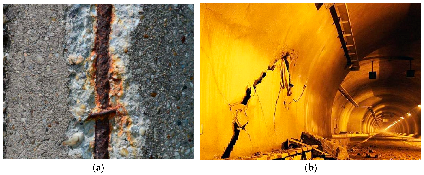
1. Introduction
2. Experimental Study on Secondary Lining Structure of Tunnels
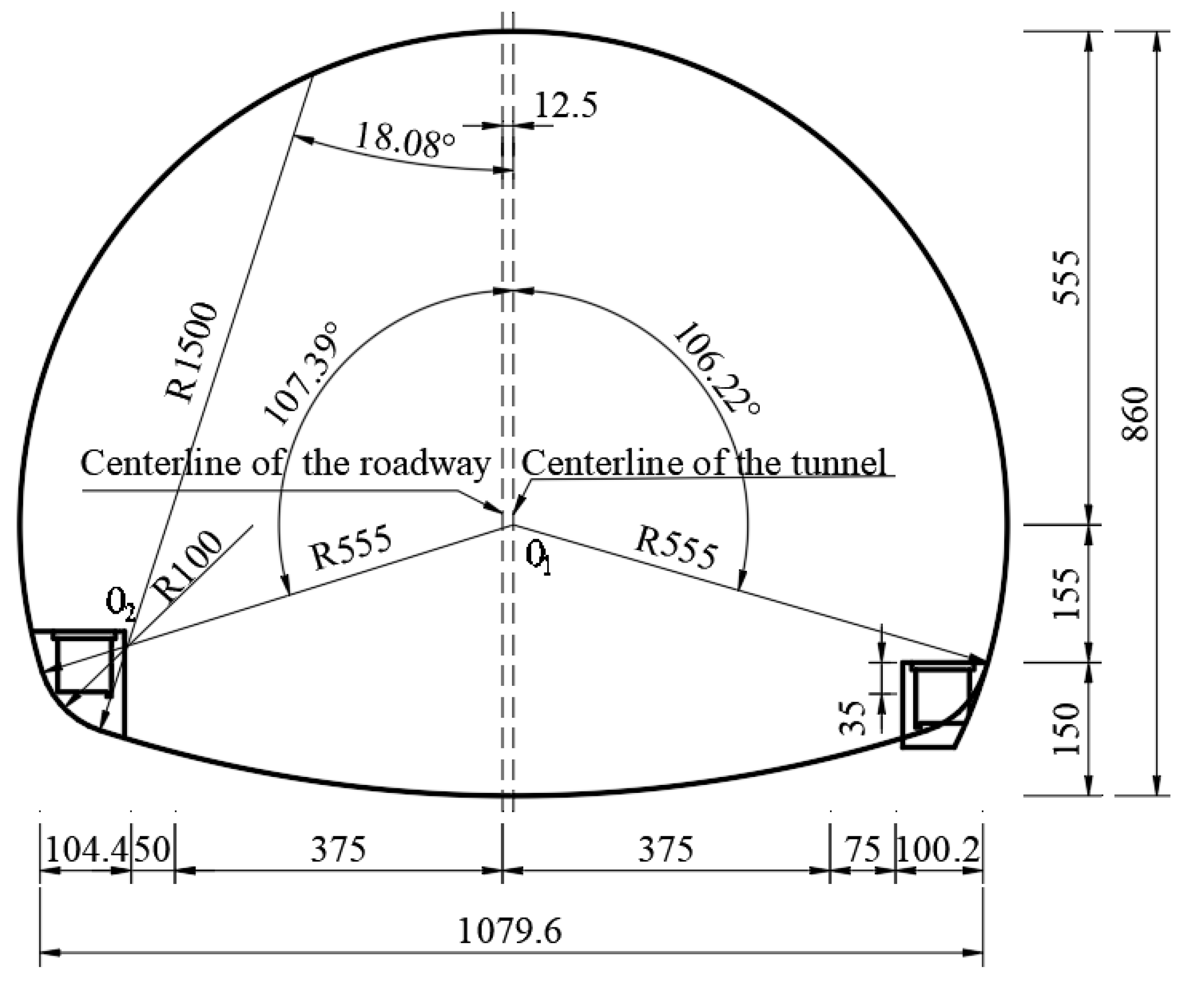
2.1. Engineering Background
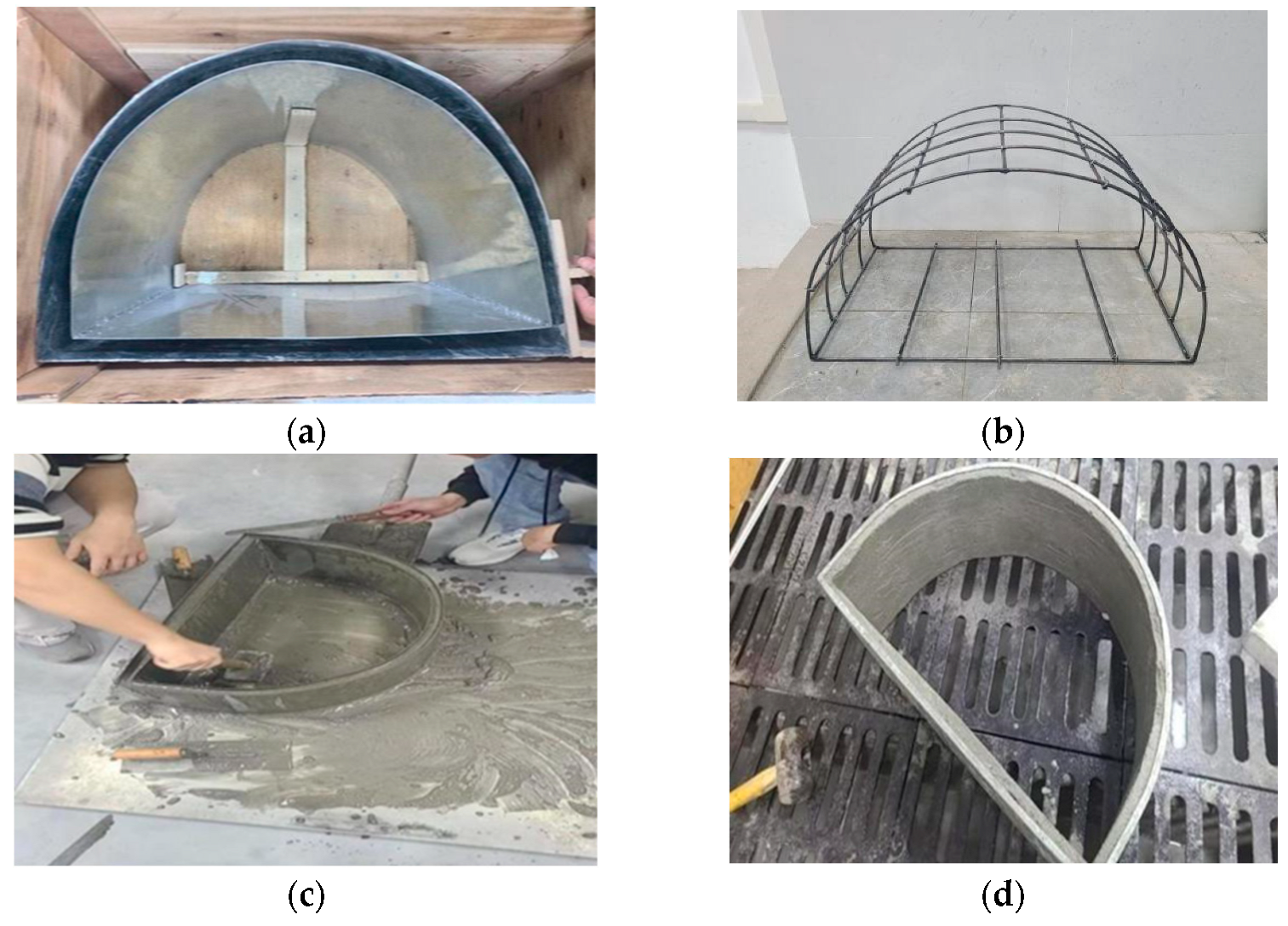
2.2. Similarity Ratio Design and Material Selection
2.2.1. Similarity Ratio Design
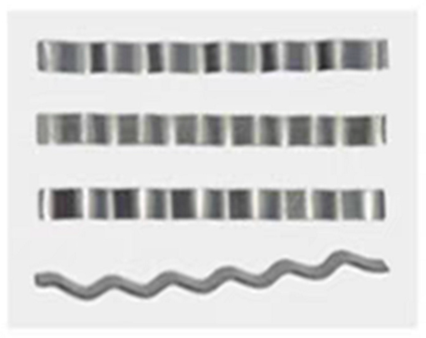
2.2.2. Material Selection
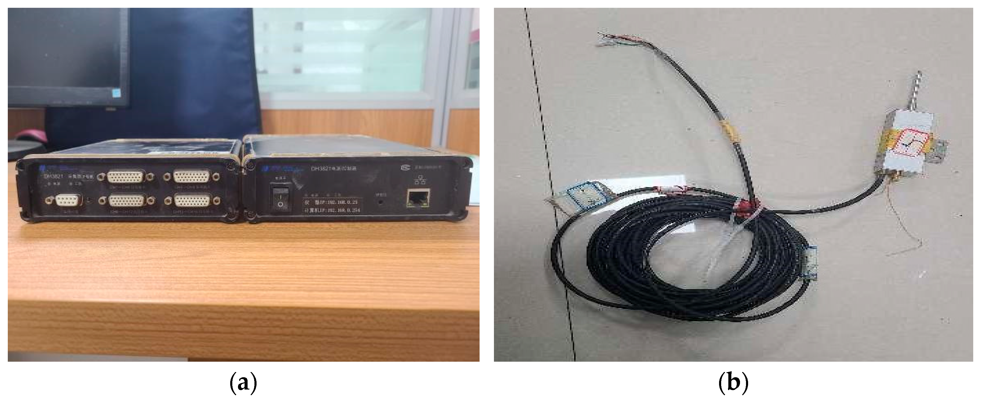
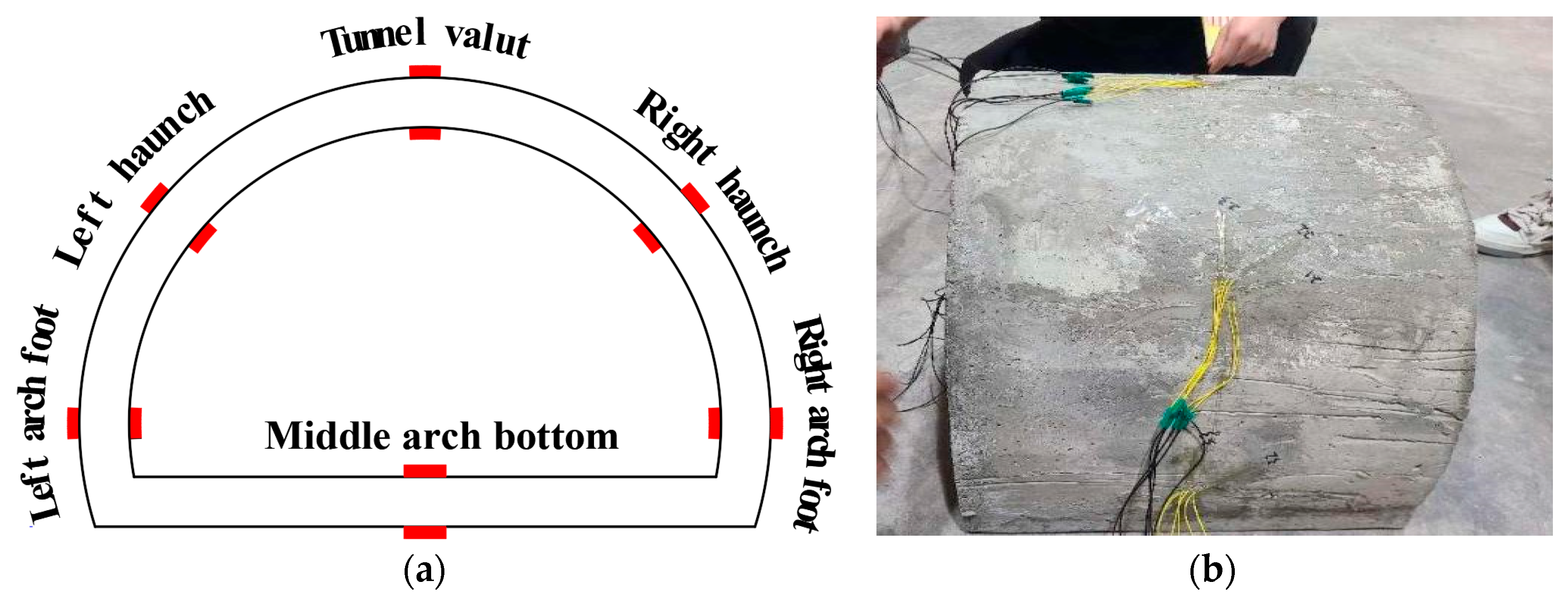
2.3. Experimental Testing Instruments and Testing Methods
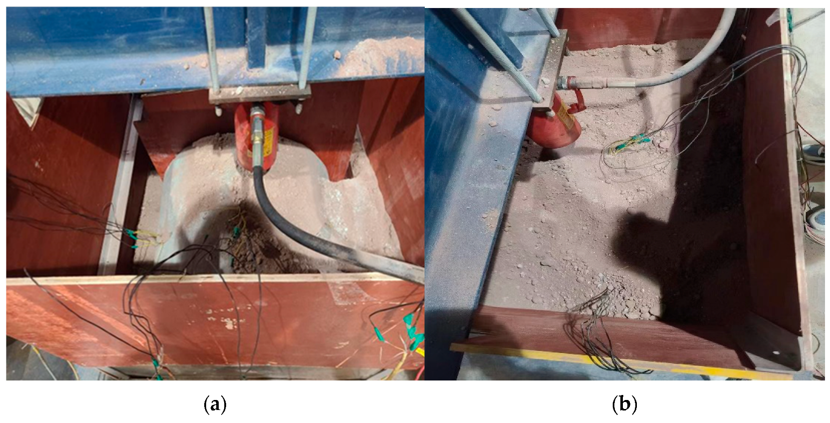
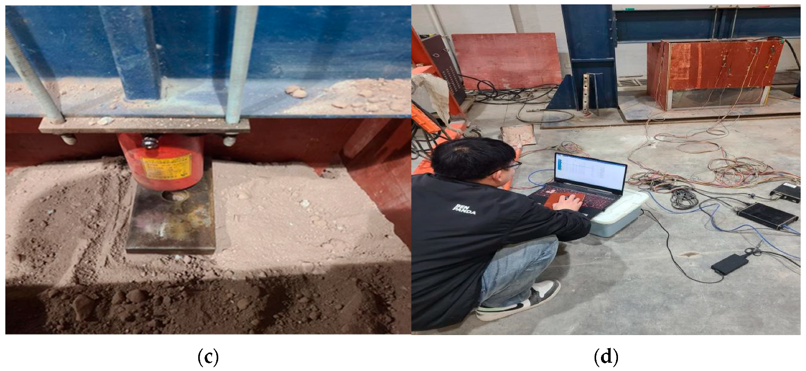
2.4. Model Load Testing
3. Analysis of Experimental Results
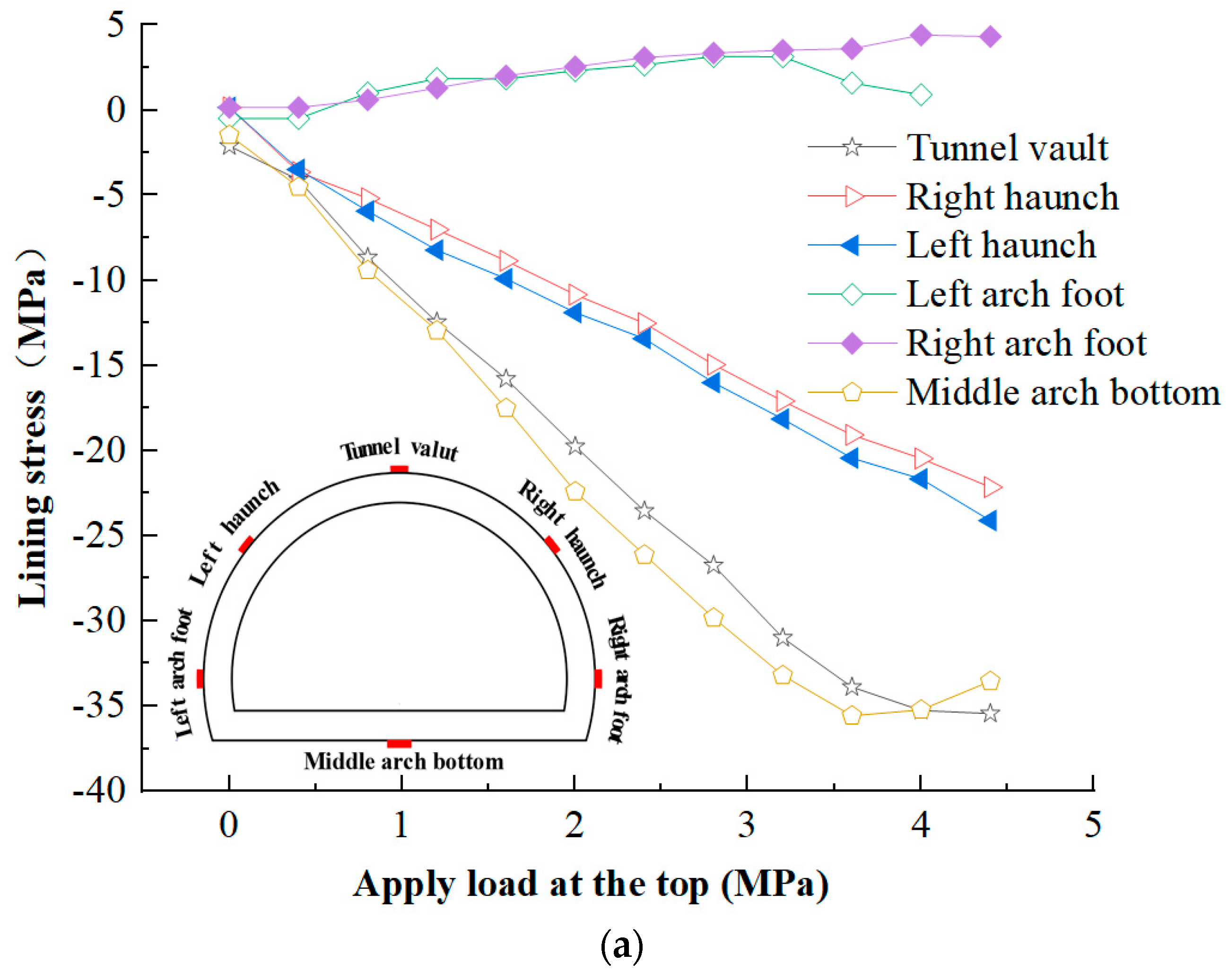
3.1. Analysis of Outer Lining Stress in Tunnels
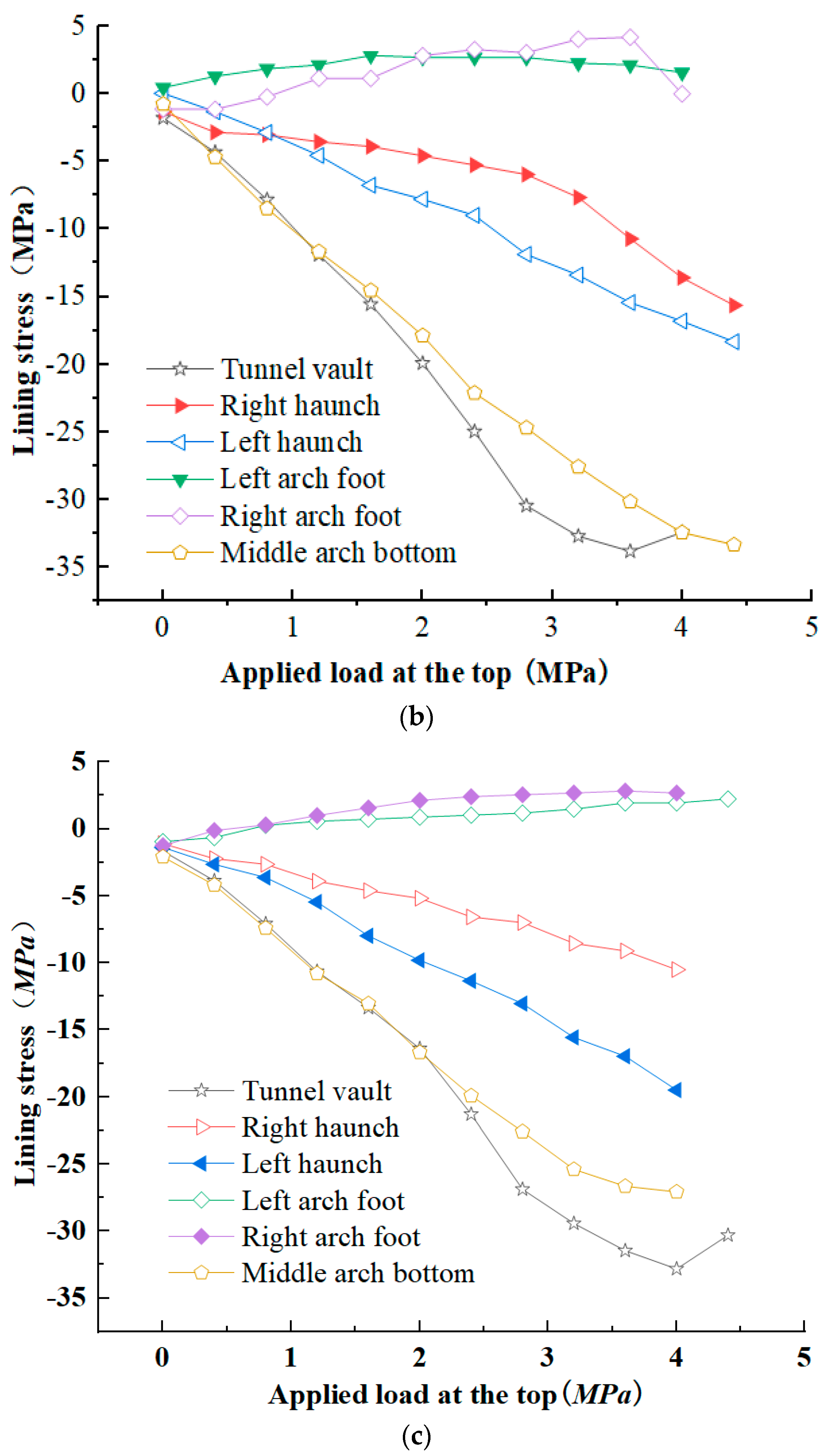
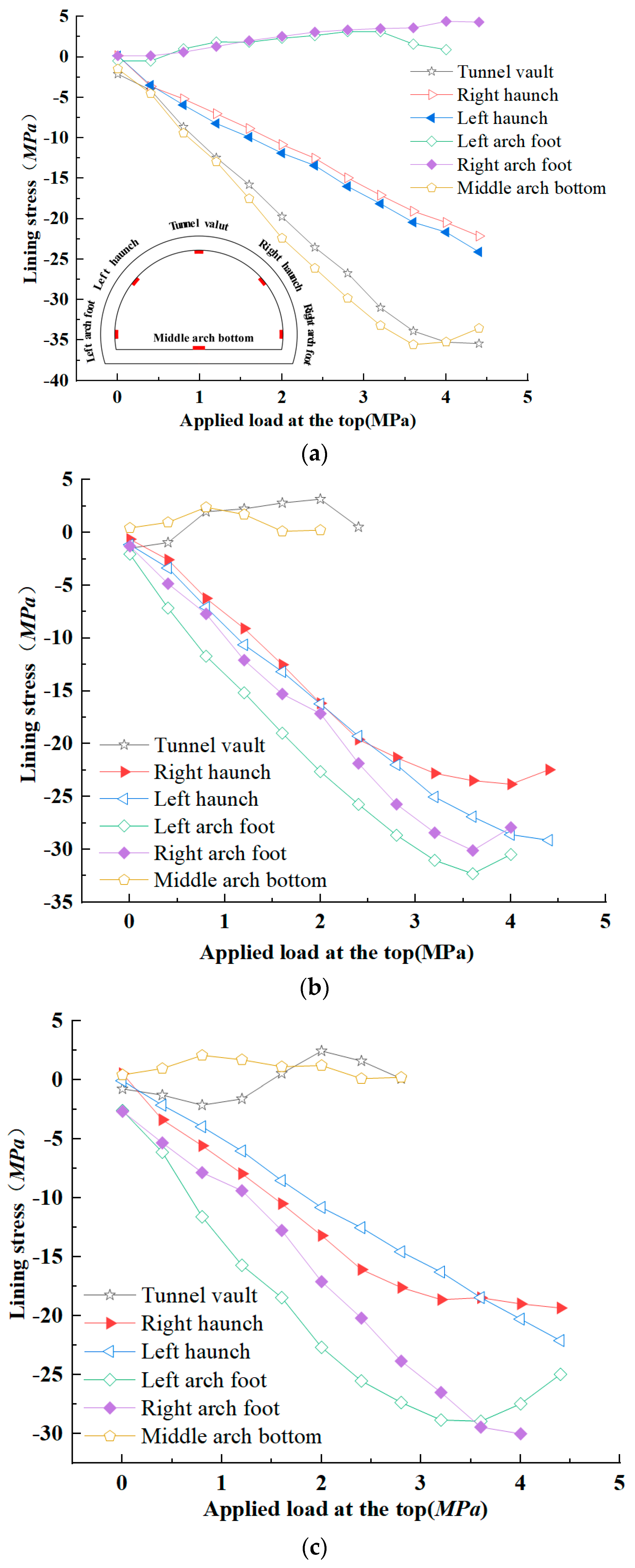
3.2. Analysis of Inner Lining Stress in Tunnel
3.3. Verification and Comparison of Numerical Model Results
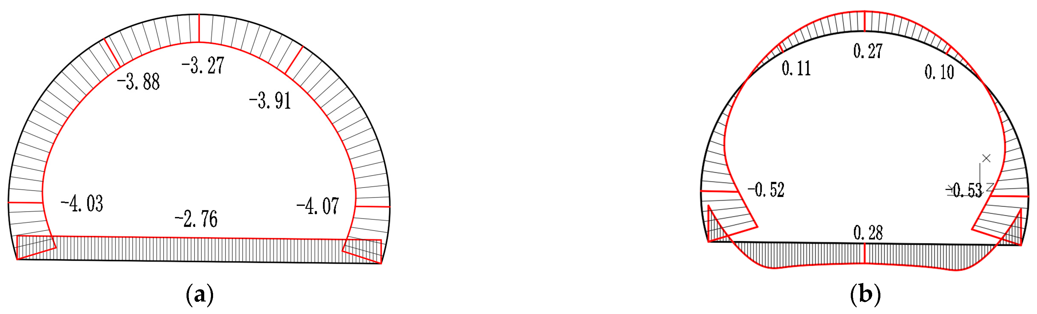
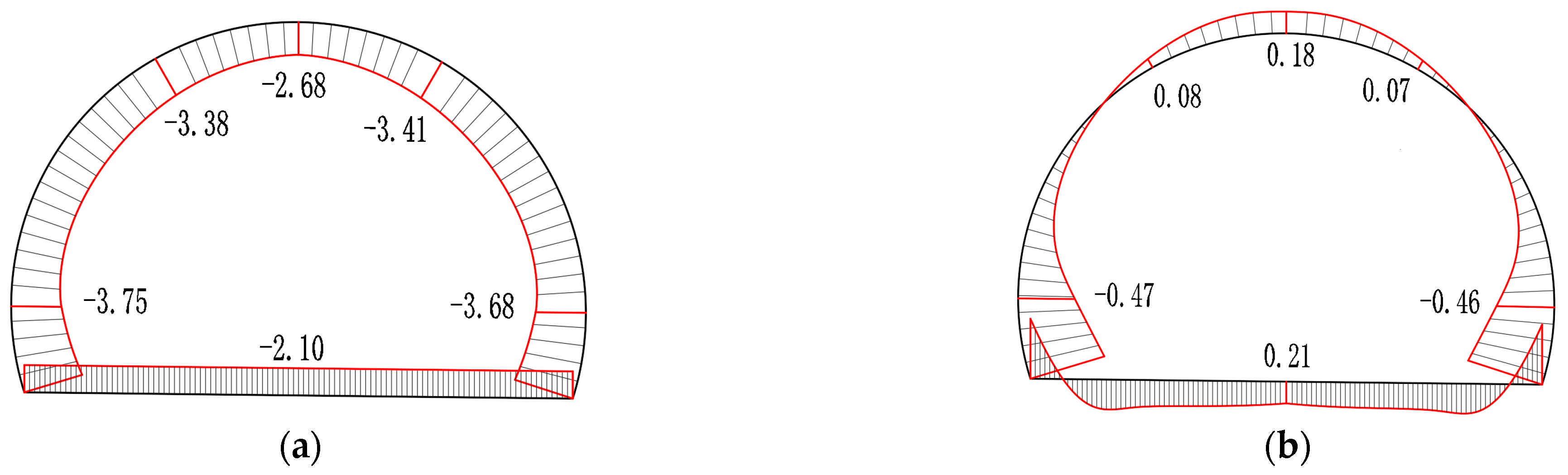
3.3.1. Internal Force Calculations for the Secondary Lining
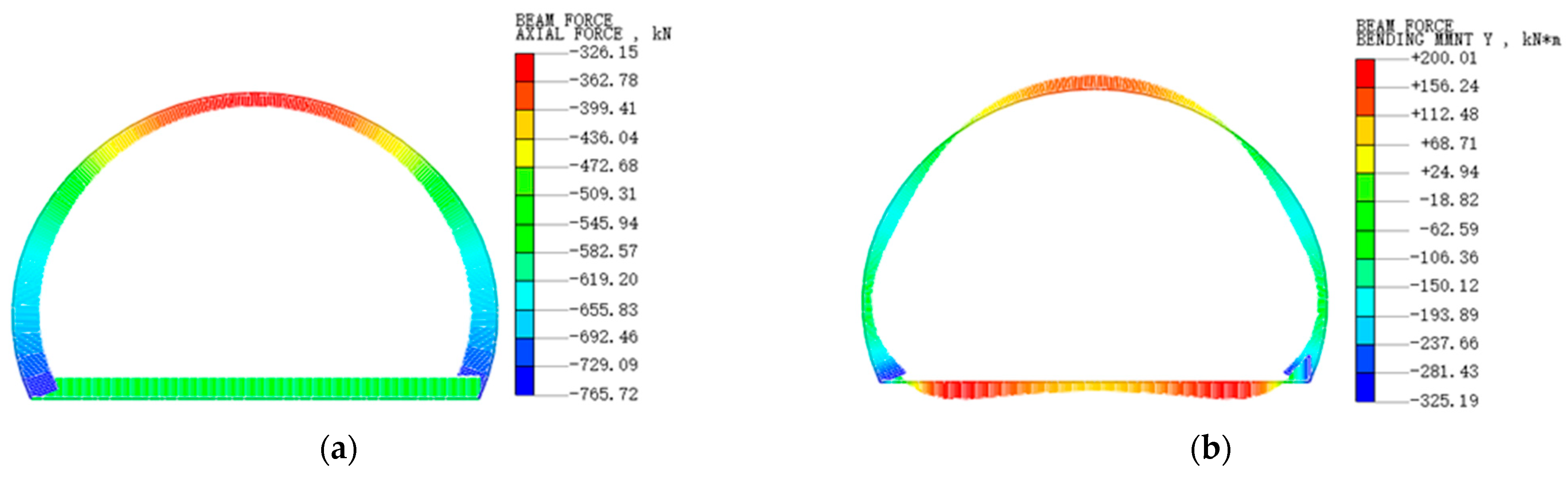
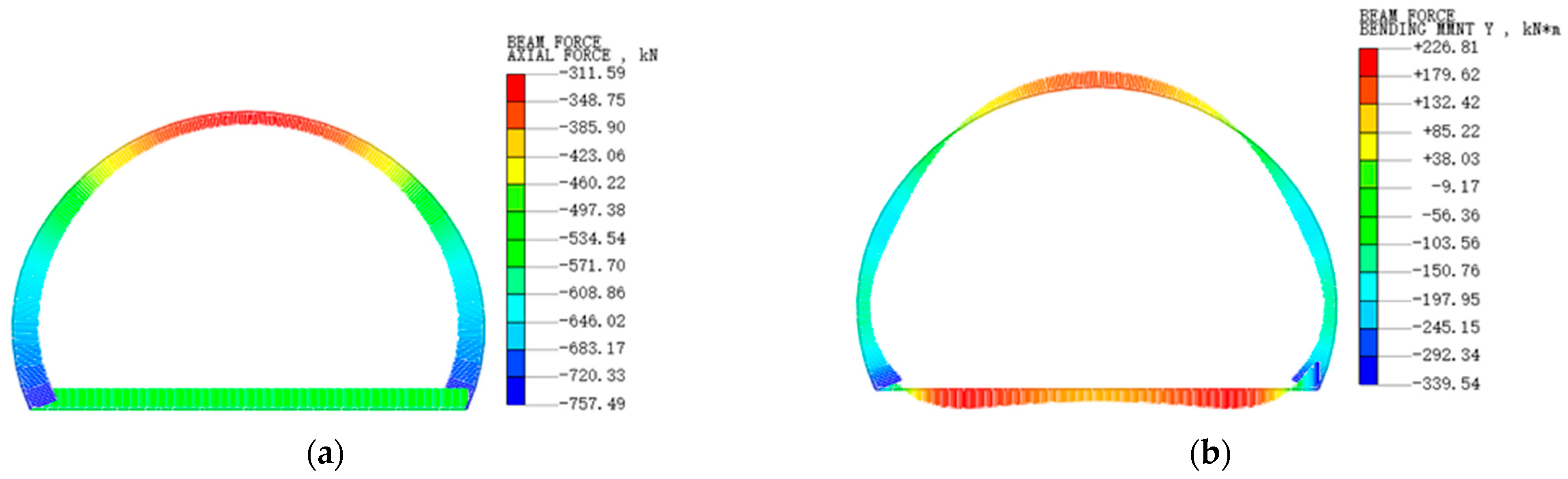
3.3.2. Numerical Model Calculation
4. Finite Element Simulation and Optimization Analysis of Support Parameters
4.1. Constitutive Relationship
- (1)
- Constitutive relationship of concrete plastic damage inelasticity
- (2)
- Constitutive relationship of steel fiber reinforcement
- (3)
- Constitutive soil modeling
4.2. Finite Element Model Establishment
4.2.1. Model Scale
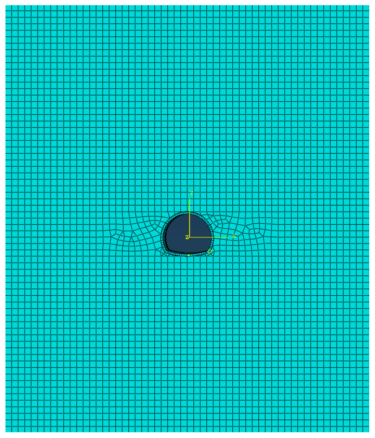
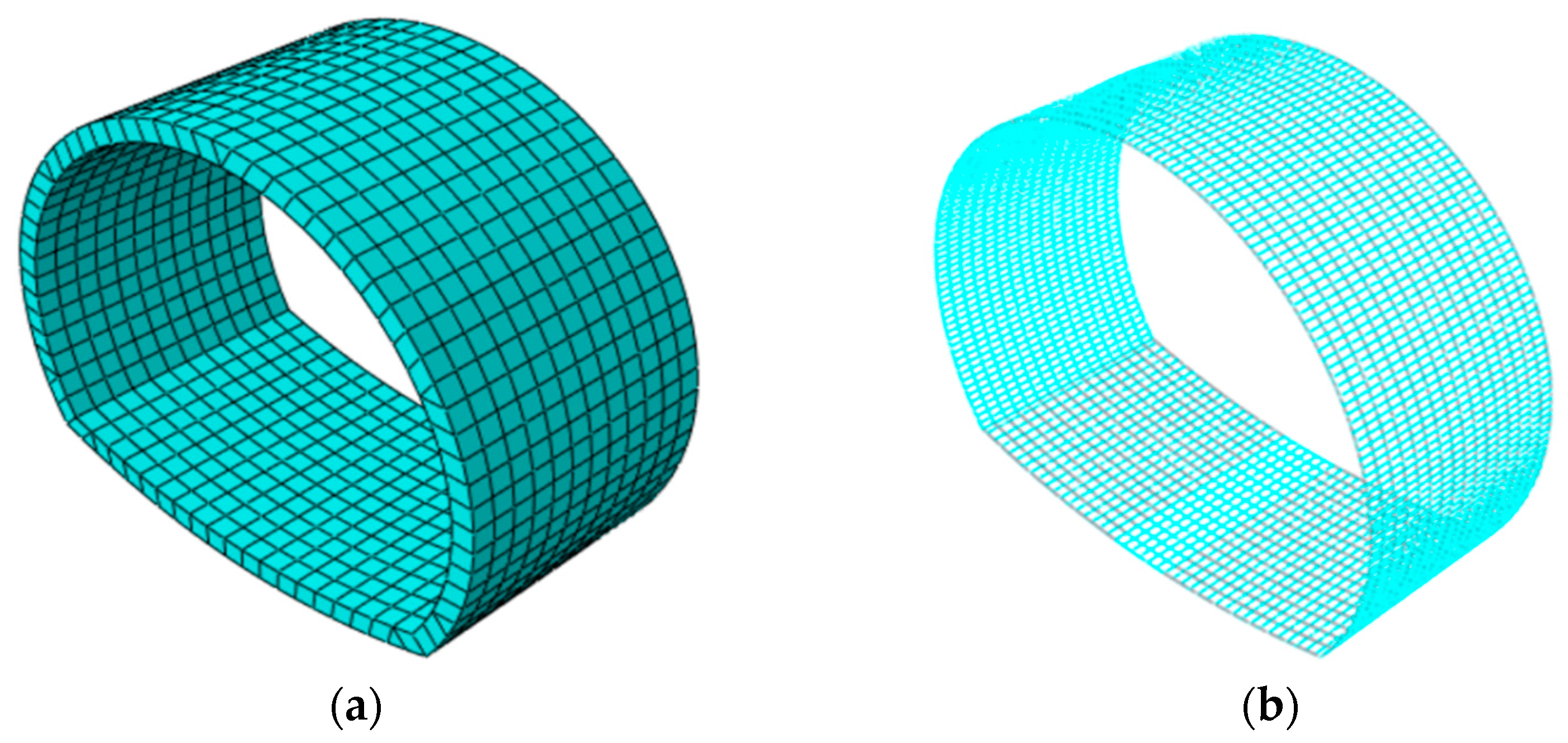
4.2.2. Model Meshing and Element Selection
4.2.3. Boundary Conditions
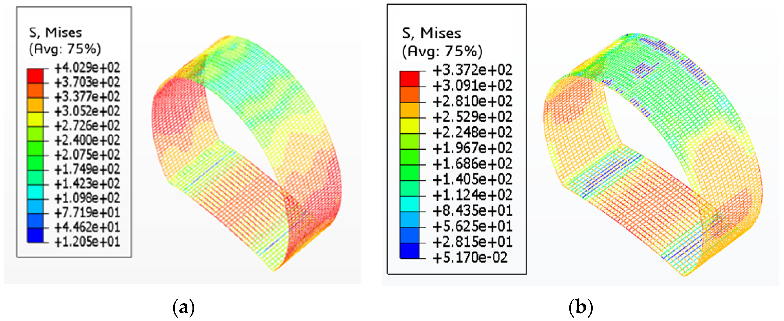
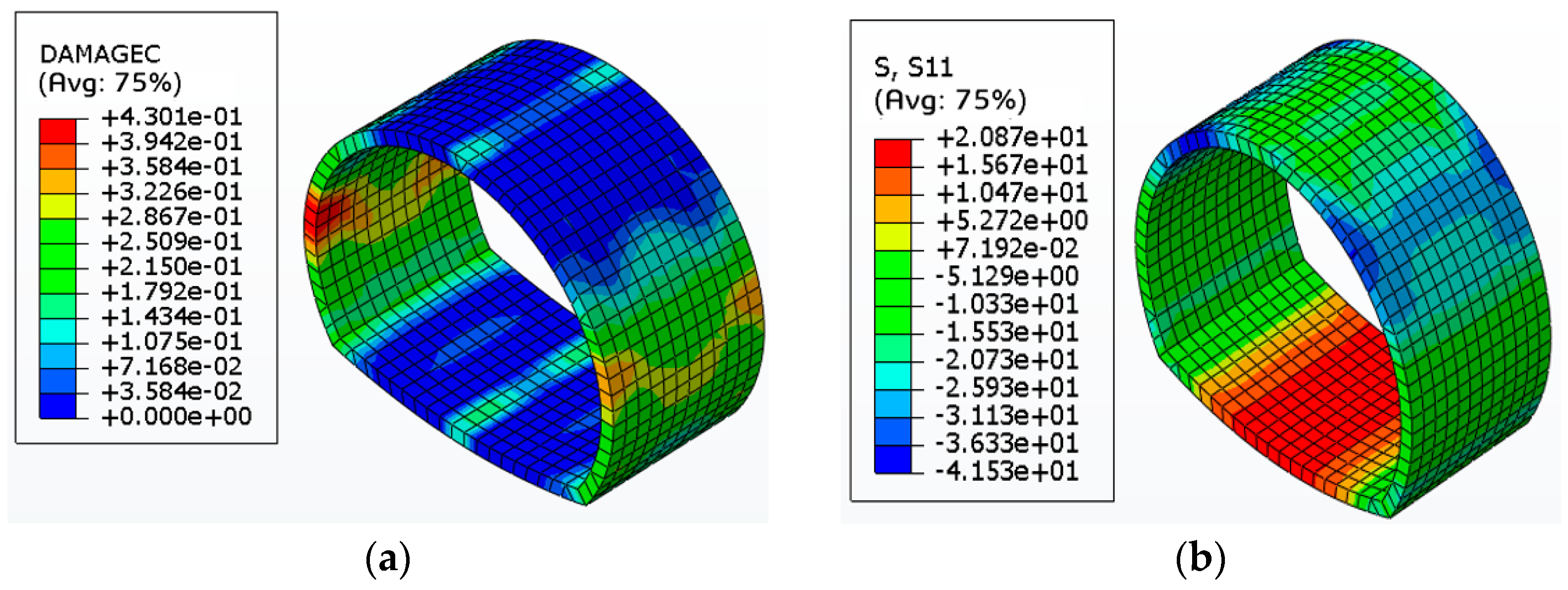
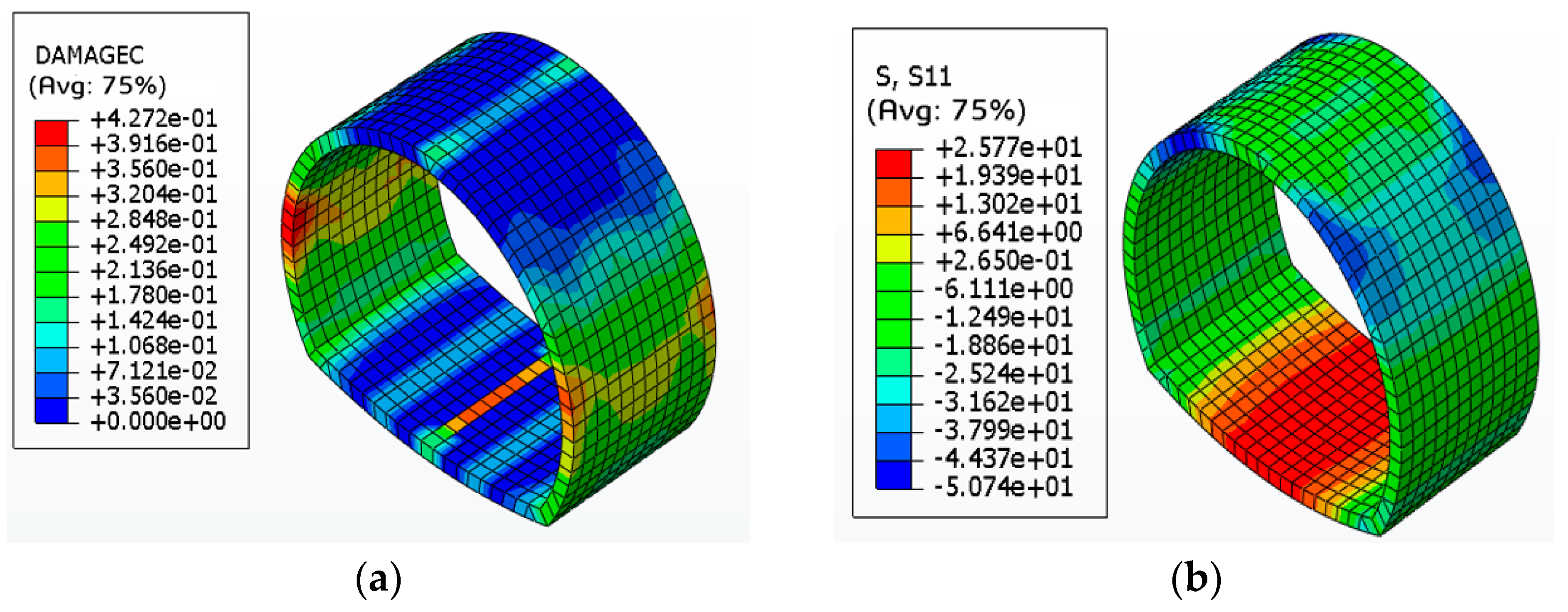
4.3. Analysis of Results
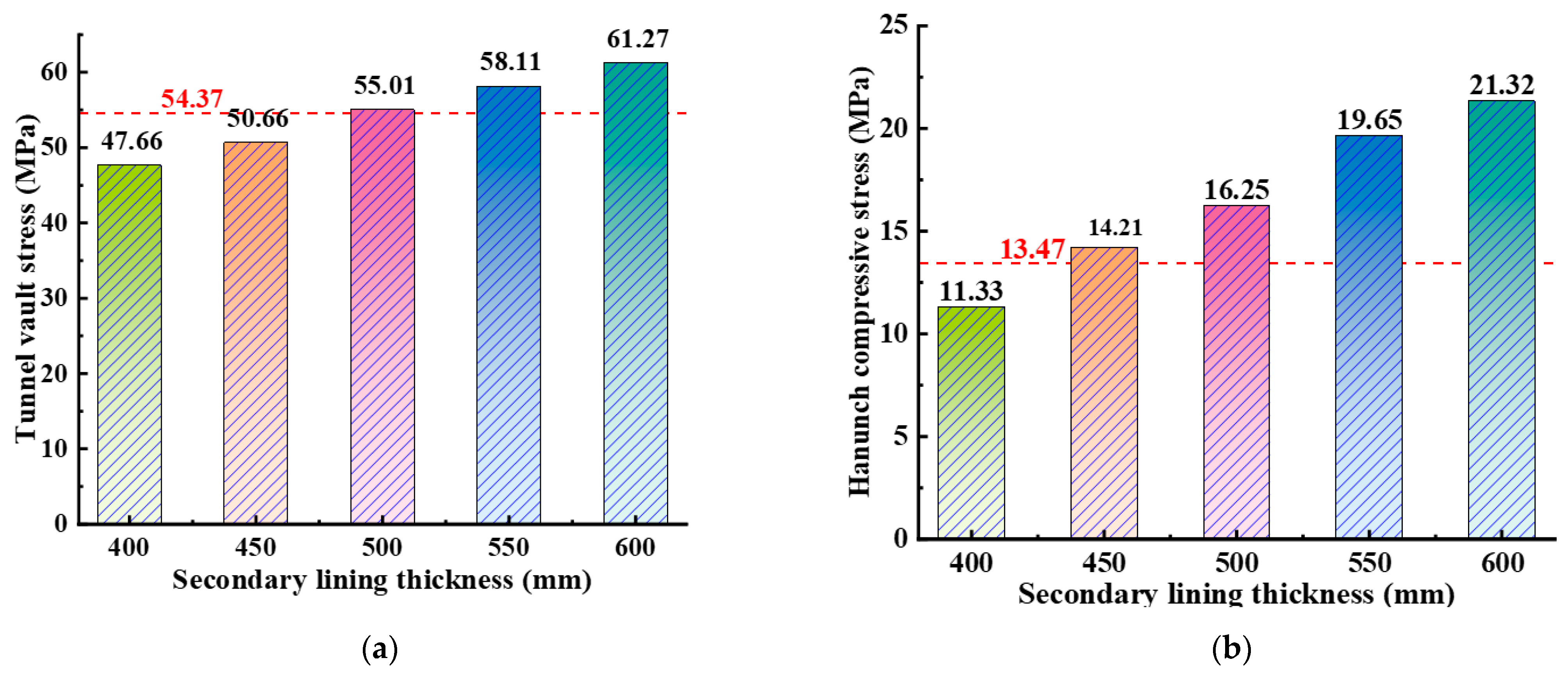
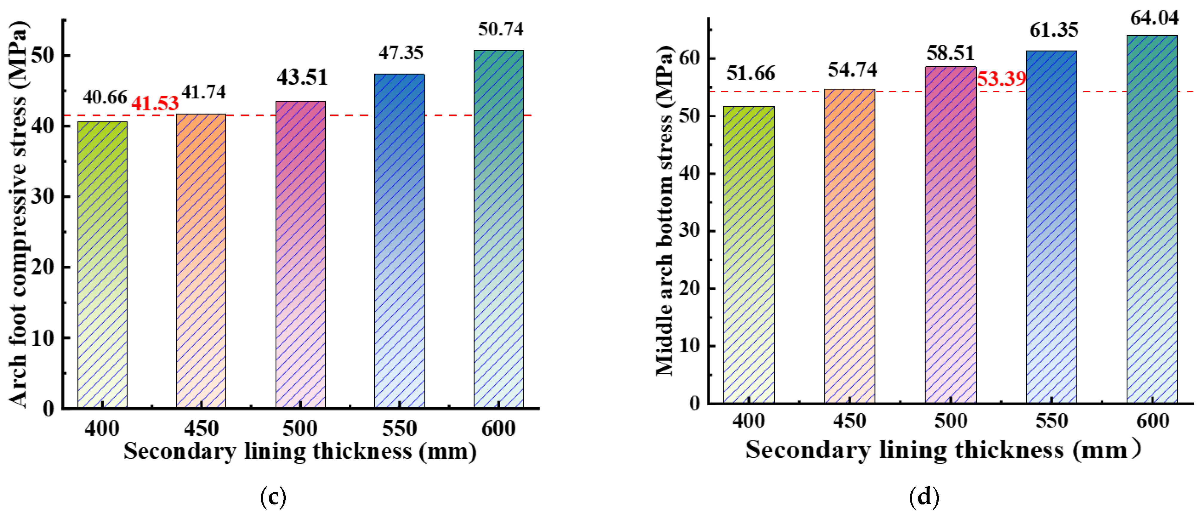
4.4. Optimization of Secondary Lining Thickness in Tunnels
4.5. Optimization of Circumferential Steel Reinforcement
5. Conclusions and Outlook
5.1. Conclusions
5.2. Outlook
Author Contributions
Funding
Data Availability Statement
Conflicts of Interest
References
- Al-Kheetan, M.J.; Al-Tarawneh, M.A.; Ghaffar, S.H.; Chougan, M.; Jweihan, Y.S.; Rahman, M.M. Resistance of hydrophobic concrete with different moisture contents to advanced freeze–thaw cycles. Struct. Concr. 2021, 22, E1050–E1061. [Google Scholar] [CrossRef]
- Deng, X. Study on Mechanical Properties of Fiber Reinforced Concret Confined by Reinforced Mesh with Low Modulus and Strong Joints. Master’s Thesis, Chongqing Jiaotong University, Chongqing, China, 2022. [Google Scholar] [CrossRef]
- Zhang, E. Experiment Study on Mechanical Properties and Durability of Complex Fiber Concrete. Master’s Thesis, Hebei University of Technology, Tianjin, China, 2007. [Google Scholar]
- Li, D. Application of steel fiber reinforced concrete technology in road and bridge construction. China High-Tech. 2024, 2, 9897–98101. [Google Scholar]
- Gao, Z. Dynamic Performance Study of Subway with Steel Fiber Concrete Lining Based on SSI Theory. Ph.D. Thesis, Liaoning Technical University, Liaoning, China, 2023. [Google Scholar] [CrossRef]
- Guo, Y. Research on the Ductility of the Steel Fiber Reinforced Concrete and Its Application in the Underground Structure Calculation. Master’s Thesis, Southwest Jiaotong University, Chengdu, China, 2008. [Google Scholar]
- Hu, X. Application and Research of Steel Fiber Concrete in Tunnel Construction. Master’s Thesis, Shijiazhuang Tiedao University, Shijiazhuang, China, 2023. [Google Scholar] [CrossRef]
- Zhang, H. Steel Fiber Reinforced Concrete Application Research in the Tunnel Weak Positions Primary Support. Master’s Thesis, Chongqing Jiaotong University, Chongqing, China, 2018. [Google Scholar]
- Hu, L. Seismic Dynamic Response Research on Steel Fiber Reinforced Concrete in Tunnel Lining Structure. Master’s Thesis, Southwest Jiaotong University, Chengdu, China, 2016. [Google Scholar]
- Li, W. Experimental Research of Waterproof for Shotcrete with Hybrid Fibers in the Structure of Tunnel Lining. Master’s Thesis, Wuhan Polytechnic University, Wuhan, China, 2015. [Google Scholar]
- Li, H.; Wu, Y.; Zhou, A.; Lu, F.; Lei, Z.; Zeng, B.; Zhu, K. Cracking Pattern and Bearing Capacity of Steel Fiber-Reinforced Concrete Single-Layer Tunnel Lining. Sustainability 2023, 15, 10665. [Google Scholar] [CrossRef]
- Wu, L.-M.; Wang, Z.-J.; Chang, Y.-Z.; Gao, F.; Zhang, B.; Wu, Y.; Fan, H.-X. Vibration Performance of Steel Fiber Concrete Tunnel Lining by Adjacent Tunnel Blasting Construction. Appl. Sci. 2023, 13, 4201. [Google Scholar] [CrossRef]
- Tiberti, G.; Minelli, F.; Plizzari, G. Reinforcement optimization of fiber reinforced concrete linings for ordinary tunnels. Compos. B Eng. 2014, 58, 199–207. [Google Scholar] [CrossRef]
- Kooiman, A.G. Modelling Steel Fibre Reinforced Concrete for Structural Design. Ph.D. Thesis, Delft University of Technology, Delft, The Netherlands, 2000. [Google Scholar]
- Nanakorn, P.; Horii, H. A fracture-mechanics-based design method for SFRC tunnel linings. Tunn. Undergr. Space Technol. 1996, 11, 39–43. [Google Scholar] [CrossRef]
- Larive, C.; Bouteille, S.; Berthoz, N.; Zappelli, S. Fiber-reinforced sprayed concrete as a permanent tunnel lining. Struct. Eng. Int. 2020, 30, 498–505. [Google Scholar] [CrossRef]
- Wang, X.; Fan, F.; Lai, J.; Xie, Y. Steel fiber reinforced concrete: A review of its material properties and usage in tunnel lining. Structures 2021, 34, 1080–1098. [Google Scholar] [CrossRef]
- JTG/T 3660-2020; Technical Specifications for Construction of Highway Tunnel. Ministry of Transport of the People’s Republic of China: Beijing, China, 2020.
- Wang, Z. Experimental Study on the Equivalent Fracture Length of Time-Dependent Fracture of Concret. Master’s Thesis, Hainan University, Haikou, China, 2019. [Google Scholar]
- Tian, Y.; Man, J.; An, J.; Liao, H.; Dou, L. Study on Dynamic Mechanical Properties and Failure Mode of Shotcrete under Cyclic Impact Loading. Study Dyn. Mech. Prop. Fail. Mode 2024, 20, 221–225. [Google Scholar]
- Bo, M. Study on the Cracking Characteristic of Asymmetric Double-Arch Tunnel Linings and its Influence on Structural Bearing Capacity. Ph.D. Thesis, Beijing Jiaotong University, Beijing, China, 2022. [Google Scholar] [CrossRef]
- Chen, F.; Yu, Z.; Yu, Y.; Liu, Q. Study on the bond-slip numerical simulation in the analysis of reinforced concrete wall-beam-slab joint under cyclic loading. Constr. Build. Mater. 2024, 449, 15. [Google Scholar] [CrossRef]
- Guo, S.; Huang, R. The AHP method of orthogonal trial. Coll. Math. 2004, 20, 114–117. [Google Scholar]
- Jia, L.; Fan, H.; Mi, X.; Shang, S.; Li, L.; Li, Z. Comprehensive performance evaluation of ceramsite concrete based on AHP weight analysis. J. Mater. Sci. Eng. 2022, 40, 774–778. [Google Scholar]
- Abubakar, A.; Idongesit, U.R.; Konitufe, C.; Mohammed, A. Prediction of Strength Properties of Concrete Containing Calcined Black Cotton Soil Using Response Surface Methodology. Am. J. Mater. Synth. Process. 2020, 5, 17. [Google Scholar] [CrossRef]
- Çetindemir, O. Nonlinear constitutive soil models for the soil–structure interaction modeling issues with emphasis on shallow tunnels: A review. Arab. J. Sci. Eng. 2023, 48, 12657–12691. [Google Scholar] [CrossRef]
- Wang, J. The Application of Abaqus in Civil Engineering; Zhejiang University Press: Hangzhou, China, 2006. [Google Scholar]
- Kuang, Z.; Liu, Z. Study on the mesh size determination method of blast wave numerical simulation with strong applicability. Heliyon 2023, 9, e13714. [Google Scholar] [CrossRef] [PubMed]
- Zhou, J.; Li, X.; Wang, Z.; Wang, Y.; Yan, C.; Jin, H. Numerical Analysis of Temperature Stress Generated by Hydration Heat in Massive Concrete Pier. Period. Polytech. Civ. Eng. 2025, 69, 461–469. [Google Scholar] [CrossRef]
- Jayaprakash, S.; Jegatheeswaran, D.; Paul, A.; Shanmugam, B. Prediction of the Mechanical Properties of Fibre-Reinforced Quarry Dust Concrete Using Response Surface and Artificial Neural Network Techniques. Adv. Civ. Eng. 2023, 2023, 8267639. [Google Scholar]
- Liu, X.; Chen, P.; Deng, Z.; Lian, N.; Xie, Y. Experimental study on the mechanical properties of polypropylene fiber-steel bar reinforced concrete pipe. Acta Mater. Compos. Sin. 2021, 38, 4349–4361. [Google Scholar]
- Ren, L. Mechanical Properties of Polypropylene Fiber Reinforced Concrete and its Application in Tunnel Secondary Lining. Master’s Thesis, Chongqing University, Chongqing, China, 2022. [Google Scholar]


| Parameters | Symbols | Similarity Ratio |
|---|---|---|
| Elasticity modulus | E | 1/20 |
| Poisson’s ratio | μ | 1 |
| Cohesive strength | C | 1/20 |
| Friction angle | φ | 1 |
| Stress | σ | 1/20 |
| Strain | ε | 1 |
| Displacement | δ | 1/20 |
| Lining Concrete | E/GPa | μ | |
|---|---|---|---|
| Reinforced Concrete | prototype | 30 | 0.21 |
| model | 1.5 | 0.21 | |
| Steel Fiber Concrete | prototype | 40 | 0.21 |
| model | 20 | 0.21 | |
| Steel Fiber-Reinforced Concrete | prototype | 41 | 0.21 |
| model | 20.5 | 0.21 | |
| Dilation Angle | Eccentricity Ratio | K | Viscous Parameters |
|---|---|---|---|
| 30 | 0.1 | 0.667 | 0.05 |
| Materials | γ/kN/m3 | V | E/GPa |
|---|---|---|---|
| Class III rock mass | 35.15 | 0.28 | 15 |
| Class IV rock mass | 29.13 | 0.32 | 6 |
| Class V rock mass | 14.15 | 0.36 | 1.5 |
| Ordinary concrete | 24.5 | 0.22 | 30 |
| Steel fiber-reinforced concrete | 24.5 | 0.21 | 40 |
| Rebar | 72 | 0.29 | 210 |
| Component Name | Total Number of Elements | Element Type |
|---|---|---|
| Rock Mass | 111,370 | C3D8R Elements |
| Tunnel Lining | 15,200 | C3D8I Solid Elements |
| Rebar Cage | 10,710 | T3D2 Truss Elements |
Disclaimer/Publisher’s Note: The statements, opinions and data contained in all publications are solely those of the individual author(s) and contributor(s) and not of MDPI and/or the editor(s). MDPI and/or the editor(s) disclaim responsibility for any injury to people or property resulting from any ideas, methods, instructions or products referred to in the content. |
© 2025 by the authors. Licensee MDPI, Basel, Switzerland. This article is an open access article distributed under the terms and conditions of the Creative Commons Attribution (CC BY) license (https://creativecommons.org/licenses/by/4.0/).
Share and Cite
Wang, Z.; Wang, Y.; Wang, X.; Rong, B.; Zhang, B.; Wu, L.; Jia, C.; Huang, Z. Mechanical Properties of Steel Fiber-Reinforced Concrete Tunnel Secondary Lining Structure and Optimization of Support Parameters. Buildings 2025, 15, 2390. https://doi.org/10.3390/buildings15142390
Wang Z, Wang Y, Wang X, Rong B, Zhang B, Wu L, Jia C, Huang Z. Mechanical Properties of Steel Fiber-Reinforced Concrete Tunnel Secondary Lining Structure and Optimization of Support Parameters. Buildings. 2025; 15(14):2390. https://doi.org/10.3390/buildings15142390
Chicago/Turabian StyleWang, Zijian, Yunchuan Wang, Xiaorong Wang, Baosheng Rong, Bin Zhang, Liming Wu, Chaolin Jia, and Zihang Huang. 2025. "Mechanical Properties of Steel Fiber-Reinforced Concrete Tunnel Secondary Lining Structure and Optimization of Support Parameters" Buildings 15, no. 14: 2390. https://doi.org/10.3390/buildings15142390
APA StyleWang, Z., Wang, Y., Wang, X., Rong, B., Zhang, B., Wu, L., Jia, C., & Huang, Z. (2025). Mechanical Properties of Steel Fiber-Reinforced Concrete Tunnel Secondary Lining Structure and Optimization of Support Parameters. Buildings, 15(14), 2390. https://doi.org/10.3390/buildings15142390