Article

Mechanical Response Analysis of High-Pile Wharf on Deep Soft Soil Foundation Under Complex Multi-Factor Interactions

School of Civil Engineering, Sun Yat-sen University & Southern Marine Science and Engineering Guangdong Laboratory (Zhuhai), Zhuhai 510275, China
*
Author to whom correspondence should be addressed.
Buildings 2025, 15(13), 2379; https://doi.org/10.3390/buildings15132379
Submission received: 12 May 2025 / Revised: 26 June 2025 / Accepted: 5 July 2025 / Published: 7 July 2025
(This article belongs to the Special Issue Non-linear Behavior and Design of Steel Structures)

Abstract

High-pile wharves are commonly used on deep soft soil foundations and are prone to the influence of complex environmental factors during long-term service. However, there is limited research on the spatiotemporal coupling effects of complex environmental factors within the integrated analysis system of high-pile wharves. Therefore, this study, based on the engineering background of a bulk high-pile wharf in Zhanjiang, combined the finite element method with static and dynamic structural analysis to establish an integrated simulation model of the wharf structure and foundation. The structural response modes of the wharf under the coupling effects of multiple factors, such as soft soil softening, wave loading, and surface load distribution, were analyzed. The results show that, considering the softening characteristics of the soft soil, the safety factor of the structure decreased by up to 18.95%. Under wave loading, the maximum displacement and maximum bending moment of the wharf structure occurred in the region affected by the wave load. Under local surface loading, the structural deformation of the wharf was more pronounced than under global surface loading. In coupled conditions, surface loading had the most significant effect on deformation and internal forces, while wave loading and the soft foundation model mainly affected the maximum displacement, with little impact on the maximum bending moment. This study provides valuable insights for the optimization of service performance and safe operation and maintenance of high-pile wharves.

1. Introduction

As a key component of maritime transportation, port wharves have grown significantly due to the continuous development of international trade and the surge in global maritime traffic. The increasing size of vessels, with their enhanced cargo capacity, has led to extension of port facilities into offshore deep-water areas [1]. High-pile wharves, as the primary type of wharf, are less affected by wave and current forces, provide stable docking conditions for large vessels, and are convenient for construction. They are widely used on deep soft soil foundations in offshore areas [2,3]. Furthermore, deep soft soil is characterized by low bearing capacity, high settlement, and high compressibility [4,5]. During long-term service, high-pile wharves are often subjected to complex environmental factors, such as soft soil sedimentation, wave loading, and heavy surface loading [6]. These factors, combined with the mechanical properties of the foundations and the external environmental influences, affect the bearing capacity and structural stability of the wharf [7,8]. However, the deformation patterns and bearing characteristics of high-pile wharf structures under multi-load conditions are highly complex and do not simply follow a linear superposition. There is limited research on the spatiotemporal coupling effects of complex environmental factors on high-pile wharves. Therefore, it is necessary to study the multi-factor mechanical coupling effects and their variation laws for high-pile wharves on deep soft soil foundations.
As a crucial foundation for high-pile wharves, the mechanical properties of deep soft soil foundations play a decisive role in the bearing capacity and structural stability of the engineering system. Deep soft soil is characterized by high water content, high porosity, and strong thixotropy [9]. Under long-term cyclic wave loading and high additional static loads, the strength of the soft soil weakens, and its stiffness decays, resulting in the deterioration of the structural bearing characteristics [10,11,12]. Given the limited lateral bearing capacity of vertical piles, double rows of piles and inclined piles are commonly arranged in the front row to enhance the lateral resistance of the structure, thus more effectively resisting environmental loads such as wave, water current, wind loads, and ship impacts [13,14]. Zhang et al. [15] found that a single-row frame model could accurately simulate and analyze the deformation characteristics of high-pile wharf pile foundations, effectively reflecting their stress and deformation patterns. Yan et al. [13] conducted an analysis of the bearing performance of the superstructure of high-pile wharves, and their results indicated that, under the interaction between the soil and the superstructure, inclined piles on the shore side and vertical piles at the wharf top experience significant bending moments. Yi et al. [16] investigated the influence of pile–soil interaction on the dynamic behavior of a fixed-base single pile, characterizing its vibrational responses along different elevations. It can be seen that existing studies have largely overlooked the effects of large deformation behavior and hysteretic characteristics of soft foundations on the load-bearing performance of high-pile wharves. Furthermore, actual soil parameters have rarely been incorporated into model analyses.
Research on the response mechanisms of high-pile wharves and their deep soft soil foundations has been ongoing for many years. Most previous studies also employed finite element models [7,9,17,18], with most scholars focusing on the effects of single factors or simple multi-factor combinations. Bo et al. [9] analyzed the internal force distribution and deformation behavior of the superstructure in high-pile wharves under the combined effects of panel loading, ship berthing, sediment deposition, and seismic forces. Wang et al. [19] focused on the nonlinear response of pile foundations under wave action, conducting a comprehensive investigation into the impact and suction effects induced by waves on pile groups. Li et al. [20] studied the internal force distribution and deformation characteristics of high-pile wharf pile foundations under soft soil sedimentary foundation conditions, showing that under sedimentation effects, the maximum bending moment occurs at the pile top, and the inclined piles on the shore side are most susceptible to structural failure. He et al. [21] and Xie et al. [22] used finite element methods and model tests to study the static and dynamic responses of wharves under wave loading or ship impact loading. Xie et al. [23] established a numerical model of inclined pile wharves based on finite element methods, systematically analyzing the effects of pile slope, cross-sectional dimensions, and frame arrangement on the performance of single piles, and derived displacement response calculation formulas for inclined pile wharves under lateral loading.
In summary, to investigate the mechanical response of high-pile wharves on deep soft soil foundations under complex multi-factor interactions, this study was based on a real project in Zhanjiang, China. Using the ABAQUS 2021 finite element software, a computational model was developed incorporating soil stiffness degradation and wave loading effects through the implementation of UMAT and DLOAD subroutines. Realistic soil mechanical parameters were obtained from triaxial tests, and an integrated three-dimensional simulation model of the wharf structure and soft foundation was established. The study investigated the response patterns and bearing capacity variation of the high-pile wharf under complex environmental conditions, including soft soil sedimentation, wave loading, and pile surface distribution. Therefore, through this systematic study, the mechanical response patterns and deformation correlation effects of high-pile wharves on deep soft soil foundations under the influence of multiple factors can be fully and comprehensively explained.

2. Numerical Model Construction

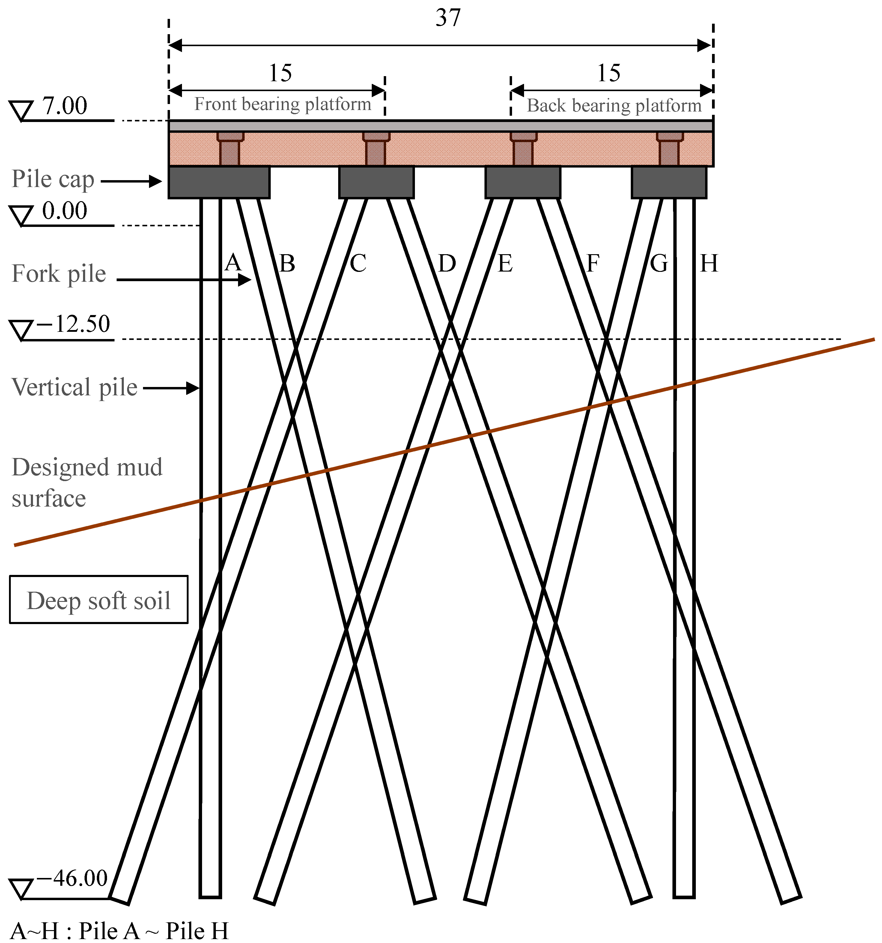
2.1. Project Description

This study is based on a high-pile bulk cargo wharf in Zhanjiang, China. The wharf is designed for 300,000 tons class bulk cargo ships, with the structure reserved for 400,000 tons class vessels. The total length of the high-pile wharf is 450 m, with a width of 37 m. The superstructure of the wharf consists of cross beams, prefabricated longitudinal beams, prefabricated panels, bearing platform, pile caps, vertical piles, and fork piles. The spacing between the frame composed of cross beams and base piles is 8.6 m, with each frame consisting of 8 steel pipe piles, A–H, including two pairs of semi-fork piles. The inclination of the inclined piles is 4:1, while the two pairs of fork piles have an inclination of 3:1. The design diagram of this high-pile wharf is shown in Figure 1.

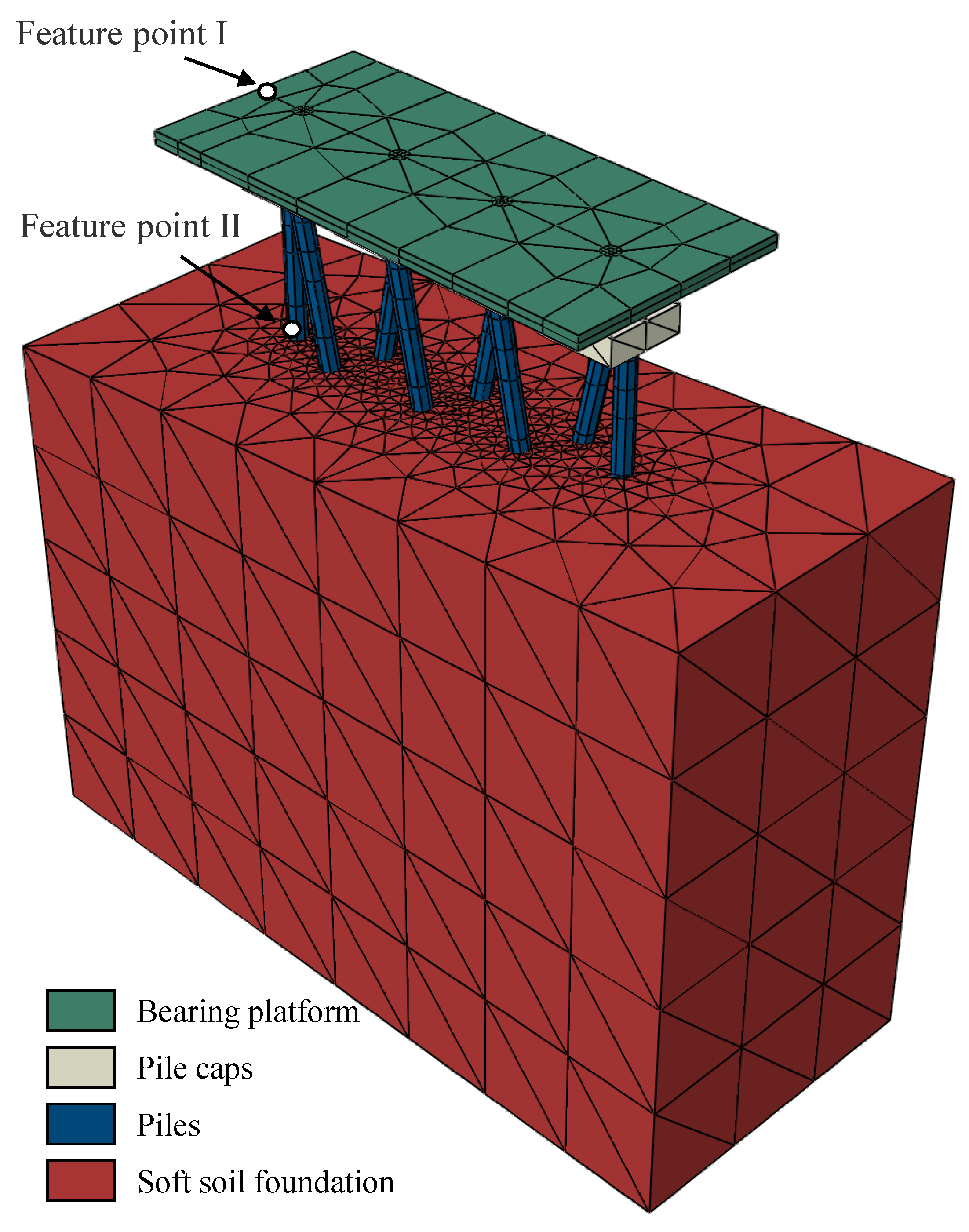
2.2. Finite Element Model Construction

This study selected a single lateral frame of the wharf as the research subject, using Abaqus as the finite element analysis software (as shown in Figure 2). The dimensions of the wharf’s superstructure platform are 37 m in length, 17 m in width, and 1 m in thickness, with C30 concrete used. The density of C30 concrete is 2500 kg/m3, the elastic modulus is 2.9 × 10¹⁰ Pa, and the Poisson’s ratio is 0.2. The foundation slab is 6 m in length, 6 m in width, and 2 m in thickness, using C50 concrete. The density of C50 concrete is 2550 kg/m3, the elastic modulus is 3.5 × 10¹⁰ Pa, and the Poisson’s ratio is 0.2. The vertical piles are 50 m in length and 1.4 m in diameter, while the inclined piles are 52 m in length and 1.3 m in diameter, both made of Q345B steel. The lower soft soil foundation is 60 m in length, with a maximum height of 45 m, a minimum height of 40 m, and a width of 25 m. The distance between the piles and the model boundaries is greater than 5 times the pile diameter. The soil constitutive model was based on the Darendeli viscoelastic model, which is an improvement of the Hardin–Drnevich theory under the Kondner hyperbolic assumption, and was embedded into the overall model analysis using the UMAT subroutine based on experimental results. The wharf platform and pile foundations were modeled using C3D4 elements to effectively capture the structural response. The surrounding clay was also discretized with C3D4 elements, incorporating a user-defined UMAT subroutine to simulate the nonlinear behavior of soft soil. To accurately represent stress concentrations and soil–structure interaction effects, mesh refinement was applied in critical regions such as the pile–soil interface and pile heads. The mesh size in these regions was determined through a mesh convergence study to ensure a balance between numerical accuracy and computational efficiency.
The wall thickness of the steel pipe piles used in the high-pile wharf structure is t = 18 mm. During the iterative analysis of the steel pipe piles, convergence issues may arise due to excessively large aspect ratios of the mesh elements. To address this, the wall thickness of the steel pipe piles was increased in the modeling process. Based on the principles of minimum yield stress, mass equivalence, and flexural stiffness equivalence [24], the equivalent material properties used in the finite element model were determined as follows: density of 785 kg/m3, elastic modulus of 20.6 GPa, and minimum yield stress of 34.5 MPa.
The pile–soil interaction below the seabed was modeled using contact pairs defined in the software. The interaction was simulated by assigning master and slave surfaces, with the steel pipe pile surfaces, having significantly higher stiffness than the surrounding soil, designated as the master surface, and the soil surfaces as the slave surface. A surface-to-surface contact type was adopted. The normal contact behavior was defined using the “hard” contact model, while the tangential behavior was governed by Coulomb friction, with a friction coefficient set to 0.25.

2.3. Calculation Procedure

The numerical simulation in this model consisted of three consecutive calculation steps: (1) The superstructure of the wharf was removed, and only the self-weight of the foundation was applied. Geostatic equilibrium was achieved using the ODB import method, which consists of four sequential steps: initial analysis, result extraction, new model setup, and structure activation [25]. The bottom boundary of the soil model was constrained in the x, y, and z directions, while the side boundaries were restricted in their normal directions. (2) The wharf structure was activated to calculate the deformation and internal forces of the wharf and the foundation under self-weight loading. (3) Uniform loads were incrementally applied at various positions on the cap beams to simulate surface loading, and the interaction between soil deformation and wharf structural response was analyzed. To assess the influence of various factors on soil deformation and wharf structural response, a parametric study was performed with the soft-foundation model, wave loading, and load distribution as variables. In addition, a mesh sensitivity analysis was conducted by varying mesh density and monitoring key response parameters, namely, pile head displacement and bending moments. The selected mesh configuration ensured mesh-independent results within an acceptable tolerance.

3. Results and Discussion

3.1. Soft Foundation Analysis

In this study, the Darendeli viscoelastic model, developed based on the modified Hardin–Drnevich theory under the Kondner hyperbolic assumption [26], was adopted as the constitutive model for soft soil. This model efficiently captures the hysteresis behavior and stiffness degradation of soft soil under cyclic loading conditions, even with limited experimental data, as expressed in Equation (1).
E d = E d m a x 1 + ( σ d σ r ) c
Here, σr represents the strain value when Ed/Edmax = 0.5, and c is a fitting parameter. Edmax is the maximum dynamic modulus obtained from the Hardin model (Equation (2)) as the dynamic strain εd approaches zero, as shown in Equation (3), where a and b are fitting parameters.
E d = 1 a + b ε d
l i m ε d 0 E d m a x = 1 a
The variation of the dynamic elastic modulus of soft soil with strain under different confining pressures was obtained through triaxial tests, as shown in Figure 3. The normalized stiffness degradation curves of soft soil were obtained by fitting the data using Equation (1). Figure 4 illustrates the stiffness degradation behavior of deep soft soil under different confining pressures. As the confining pressure increased, the maximum dynamic shear modulus Edmax also increased. With increasing dynamic strain εd, the normalized dynamic shear modulus ratio Ed/Edmax showed a significant decrease, indicating a pronounced nonlinear degradation trend. Moreover, the rate of stiffness degradation became slower at higher confining pressures, suggesting that soil under greater overburden stress was able to retain higher stiffness under dynamic loading. The stiffness degradation characteristics of soil directly influence the dynamic response of the pile–soil system. Under external dynamic loading, the reduction in soil stiffness leads to increased lateral displacement of piles and higher bending moments along the pile shafts. Therefore, it is essential to adopt appropriate modulus degradation models in dynamic analyses of deep soft soil to enhance the accuracy of the interaction analysis between the wharf structure and the foundation. The normalized stiffness degradation parameters should be converted into input parameters required by numerical models to ensure better alignment with engineering practice. This method effectively captures the hysteretic behavior and stiffness degradation characteristics of deep soft soil foundations, and has been widely adopted in previously published studies [27,28,29,30,31].
Based on the FORTRAN language and the ABAQUS user subroutine interface, the stiffness degradation model for soft soil was embedded into the finite element numerical model via the UMAT subroutine. The key implementation steps were as follows: (1) declare the subroutine interface and define input and output parameters; (2) read and verify material parameters and initialize material properties; (3) perform stress decomposition and calculate invariants to obtain the equivalent dynamic stress; (4) update the dynamic elastic modulus based on the current equivalent dynamic stress σd; (5) calculate the elastic matrix to obtain the shear modulus G, bulk modulus K, and Lamé constant λ, initialize the Jacobian matrix, and finally populate the elastic matrix; (6) update the stress using the incremental elastic update method. The key material parameters of the constitutive model include Ed, σr, c, and μ.
In general, during the design phase of a wharf, it is difficult to account for the large deformation and hysteresis characteristics of deep soft soil. If the soft soil stiffness degradation viscoelastic model proposed in this study is used for the foundation, it may influence the original design to some extent, necessitating a reconsideration of the structural yield bearing capacity of the wharf. Therefore, an instability criterion is introduced, represented by the loading factor α, which is used to quantify the safety factor of the soft foundation under external forces [32]. It is defined as:
α = P / P D
In the equation, P represents the applied load during the calculation, and PD is the design load. The design load for this wharf is 200 kPa. The loading factor α is determined using the double tangent method applied to the load-displacement curve of the structure. The upper outer side of the front caisson is defined as feature point I, and the junction between pile A and the mud line is defined as feature point II, as shown in Figure 2.
The displacement-loading factor curves for feature points I and II, obtained using the commonly used M-C constitutive model for soil and the viscoelastic constitutive model proposed in this study, are shown in Figure 5. From the figure, it can be seen that when using the M-C constitutive model, the safety factors at feature points I and II are 25.92 and 18.79, respectively. When using the viscoelastic constitutive model proposed in this study, the safety factors at feature points I and II are 23.86 and 15.23, respectively. The safety factor at the front caisson is much higher than at the junction of pile A and the mud line. When considering the stiffness degradation of the soil, the safety factors of the wharf structure are reduced to some extent. Specifically, the safety factor at feature point I decreases by 7.95%, and at feature point II, it decreases by 18.95%. It can be concluded that neglecting the stiffness degradation characteristics of deep soft soil under high additional loads and its hysteretic behavior under dynamic loading may lead to an overall overestimation of the wharf’s bearing capacity during the design stage, thereby compromising the reliability of the structural safety assessment. Therefore, a viscoelastic constitutive model incorporating soil stiffness degradation is adopted in the subsequent analysis of the wharf.

3.2. Wave Analysis

In calculating the wave load, the design wave load condition for this wharf was selected as the high tide level that occurs once every 10 years during normal operation. In this study, the water depth at the mud line of the wharf seabed is h = 12 m, the design high tide level is 3.98 m, the design wave height is H = 4.05 m, the wave period is 11.5 s, and the wavelength is L = 117 m. The calculation of wave forces on cylindrical piles is shown in Figure 6. The steel pipe piles in the project are small-scale cylindrical piles, so the horizontal wave load acting on the piles can be calculated using the Morison equation [33], as shown in Equation (5). The load is then applied to the steel pipe piles using the distributed load subroutine (DLOAD) in the ABAQUS secondary development platform.
F ( t ) = F I + F D = ρ C m V u ( t ) + 1 2 ρ C d A u ( t ) | u ( t ) |
In this analysis, F(t) represents the horizontal wave force, while FI and FD are the inertia force and the drag force, respectively. The seawater density, ρ, is taken as 1.050 g/cm3 in this study. A is the reference area per unit length, where A = D, and D is the diameter of the pile column. V represents the reference volume per unit length, where V = π D 2 4 . The inertia coefficient Cm is defined as C m = 1 + C a , where Ca is the added mass coefficient, typically taken as Ca = 1 for a smooth cylinder. The drag coefficient Cd is taken as 1.2. u represents the velocity of the seawater particle, and u represents the acceleration of the seawater particle. Based on wave theory and the applicability requirements [34], the relative water depth is selected as 0.05 < h/L < 0.5, and the wave height ratio H/L < 0.05 satisfies the small wave approximation condition. Therefore, in the calculation, the Airy wave theory is used to determine u and u , as shown in Equation (6).
u = H ω 2 × c o s h   [ k ( z + h ) ] s i n h   ( k h ) c o s   ( k x ω t ) u = H ω 2 2 × c o s h   [ k ( z + h ) ] s i n h   ( k h ) s i n   ( k x ω t )
where x is the direction of wave propagation, located in the horizontal plane; t is time; H is the wave height; ω is the angular frequency; z is the distance from the pile to the seabed; and k is the wave number.
Figure 7 and Figure 8 show the horizontal displacement and bending moment distributions of the pile foundation under standard uniform design loading after the application of wave loading. As illustrated, the horizontal displacements of piles A, B, G, and H were significantly greater than those of the four intermediate battered piles. The maximum horizontal displacements occurred in the piles located closer to the shoreline, and were notably larger than those farther offshore. For piles A, B, G, and H, the peak displacements appeared at the interface where wave loading directly acted on the piles, while for piles C, D, E, and F, the peak displacements were generally located below the pile–soil interface. Regarding the bending moment distribution, vertical piles exhibited a more uniform bending moment profile than battered piles. Sudden changes in bending moment were observed in piles B and F, located within the wave loading region. The maximum bending moment occurred at pile B within the wave impact zone. For the other battered piles C, D, E, and F, the bending moments gradually increased from top to bottom, reaching their maximum near the pile base, followed by a sudden decrease. These findings indicate that wave loading had a significant effect on the bearing capacity of the wharf structure, with both the maximum displacement and maximum bending moment occurring in the wave loading region.

3.3. Stacking Surface Load Analysis

During the service period of the wharf, variations in cargo placement result in different surface load distributions, which can be categorized as acting on the front bearing platform, the back bearing platform, or the entire platform area. Figure 9 presents the distribution of horizontal displacement and bending moment of each pile under different surface load scenarios, without the influence of wave loading.
The analysis showed that when the surface load was applied only to the front bearing platform, the maximum horizontal displacement of the wharf structure occurred at the top of pile A, reaching 17.40 mm, while the maximum bending moment appeared at the top of pile G, reaching 2606 kN·m. When the surface load was applied only to the back bearing platform, the maximum horizontal displacement occurred at the top of pile H, reaching 15.39 mm, and the maximum bending moment was located near the top of pile B, reaching 3187 kN·m. Under the global surface load condition, both pile A and pile H exhibited larger horizontal displacements and bending moments, while piles B and G showed distinct bending moment fluctuations. In contrast, piles C, D, E, and F did not exhibit significant variations in displacement or bending moment. By comparing the variation patterns of pile displacement and bending moment under different yard load distributions, the following conclusions were drawn for the high-pile wharf conditions investigated in this study. Piles A and H, located at the front and back edges of the structure, exhibited high sensitivity to the spatial distribution of the yard load. In contrast, the central piles (C, D, E, and F) did not show significant abrupt changes under the three loading scenarios, indicating that their response was less influenced by the load distribution and can be regarded as a “stable zone”. Furthermore, localized concentration of loading induced a non-uniform spatial response of the pile system, with notable differences in sensitivity to load position across different pile locations. In comparison, the global loading condition produced a more continuous and smooth distribution of pile responses, reducing the likelihood of extreme stress at any specific pile location.

3.4. Multi-Factor Comparative Numerical Analysis

Based on the preceding analyses of the soft foundation, wave loads, and surface loads, it was evident that the structural response of the wharf was highly complex and not governed by a simple linear superposition of individual loading effects [18]. Therefore, it was necessary to conduct research and analysis under different loading conditions. Accordingly, 12 loading scenarios listed in Table 1 were selected, with three parallel simulations performed for each scenario. The 95% confidence intervals of the maximum horizontal displacement of the wharf structure and the maximum bending moment of the pile foundations were then analyzed.
Overall, the displacement and bending moment of the wharf structure were more sensitive to the distribution of surface loads than to wave loads and soft foundation models. Under local surface loading conditions, the maximum displacement of the wharf was significantly greater than that under global loading, with a difference of up to 8.77 mm, representing an increase of 101.6%. In contrast, the maximum bending moment under global loading was slightly higher than that under local loading, with a maximum difference of 452 kN·m, exceeding the maximum local bending moment by 14.1%. [19,35]. These findings indicate that during service, the placement of surface loads plays a critical role in the structural performance of the wharf. Concentrated loading, especially on the front bearing platform far from the shoreline, should be avoided. Wave loads tend to increase the maximum displacement of the structure to a certain extent, while their impact on bending moments is negligible. Combined with previous analyses, it was found that the maximum displacement always occurred within the wave load action zone. Therefore, this zone requires enhanced structural design and targeted monitoring during the service life of high-pile wharves. Moreover, after accounting for the softening behavior of the soft foundation, a slight increase in maximum displacement was observed, which may influence the assessment of the structural bearing capacity. Accordingly, the engineering characteristics of deep soft soil foundations should be fully considered in the structural design of high-pile wharves.

4. Conclusions

This study investigates the mechanical response behavior of a high-pile wharf in Zhanjiang, situated on a deep soft soil foundation, under the combined effects of soft foundation stiffness degradation, wave loading, and surface loading. The study analyzed the temporal and spatial distribution characteristics of the displacement and bending moment responses of the wharf structure caused by the interplay of various factors and their coupling effects. The main conclusions are as follows:
1
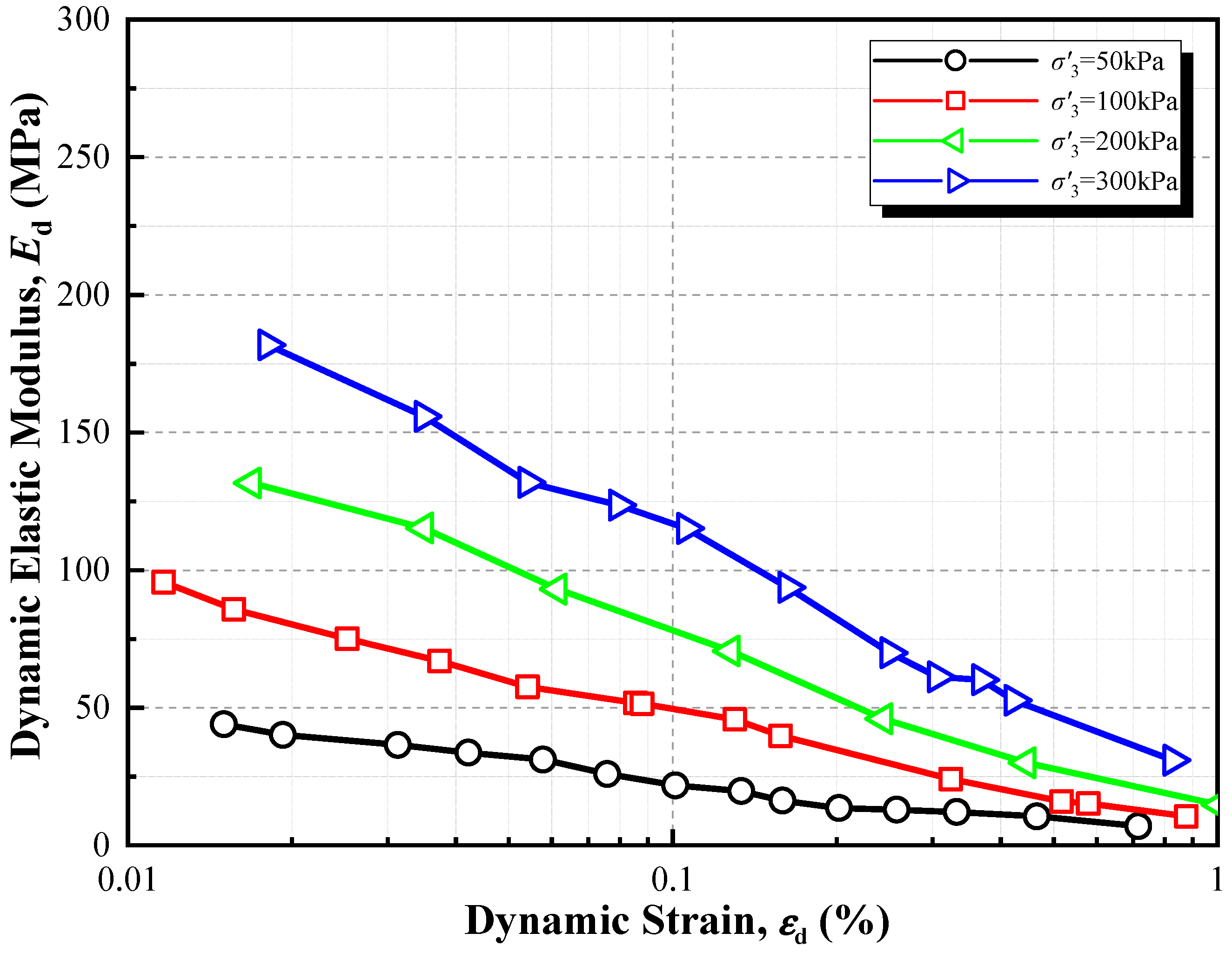
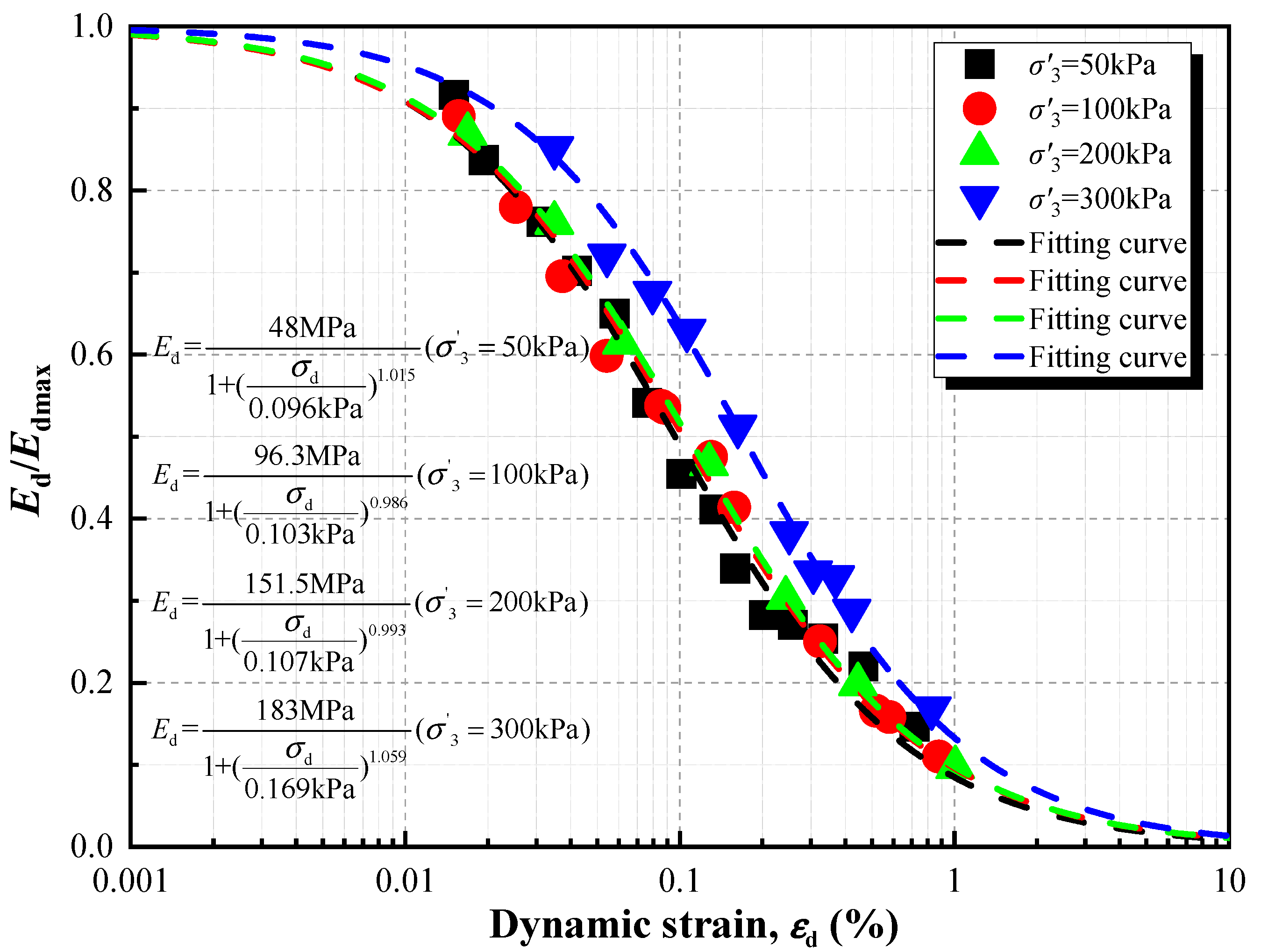
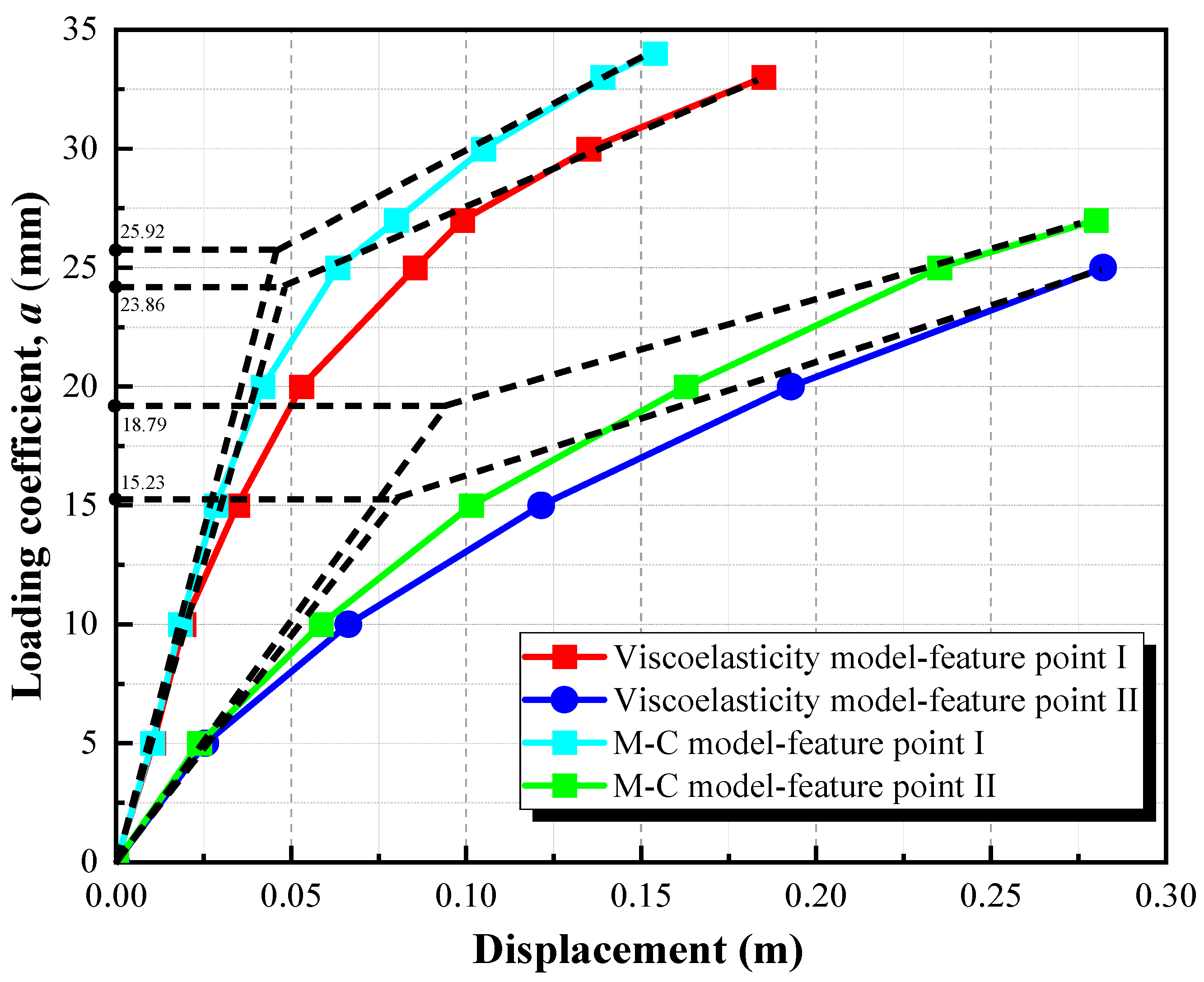
Considering the hysteretic behavior and stiffness degradation characteristics of deep soft soil foundations for high-pile wharves, the Darendeli viscoelastic constitutive model was adopted. The safety factor at critical locations of the wharf structure decreased by up to 18.95%, highlighting the necessity of accounting for large deformation and hysteretic effects of soft soil in high-pile wharf design.
2
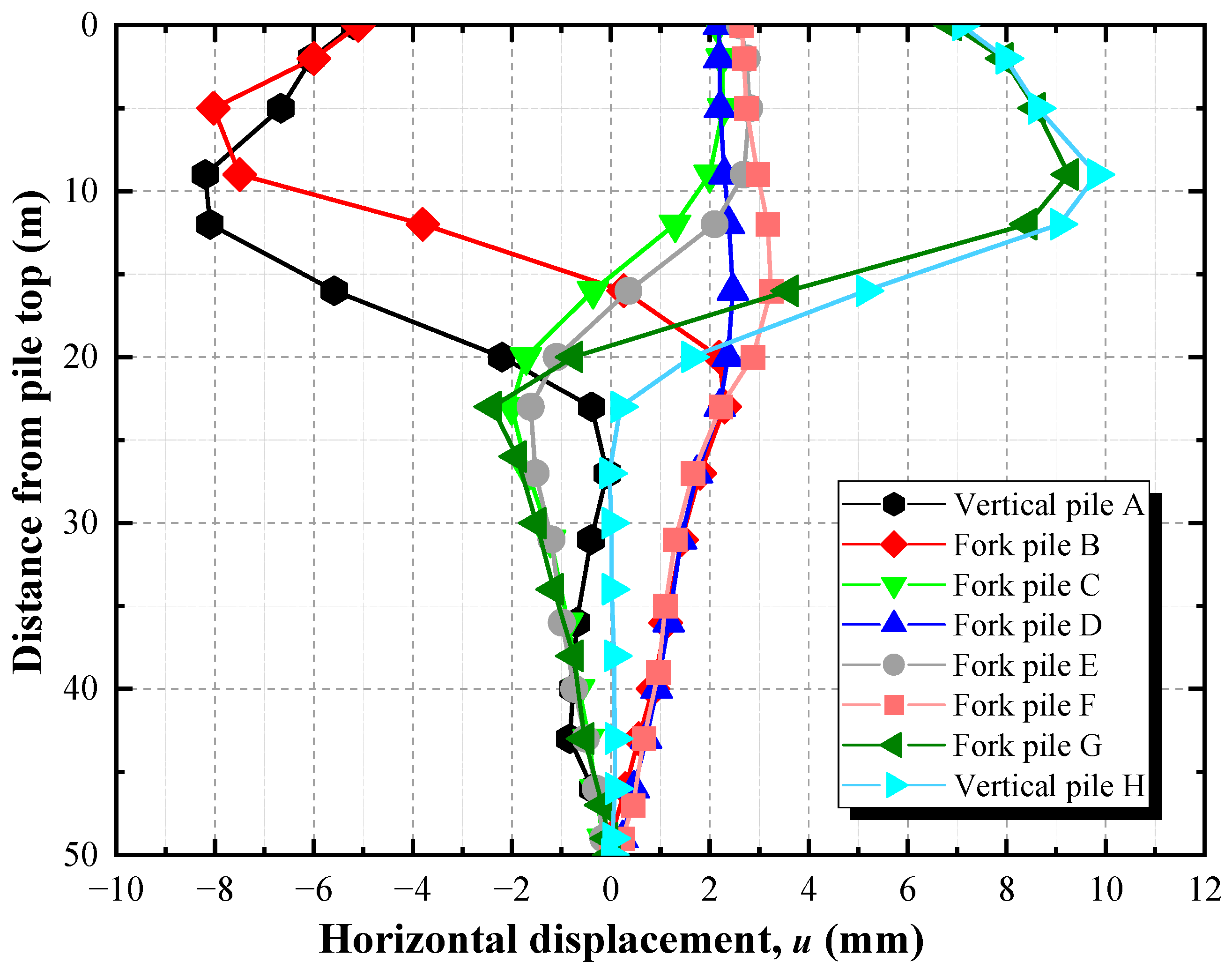
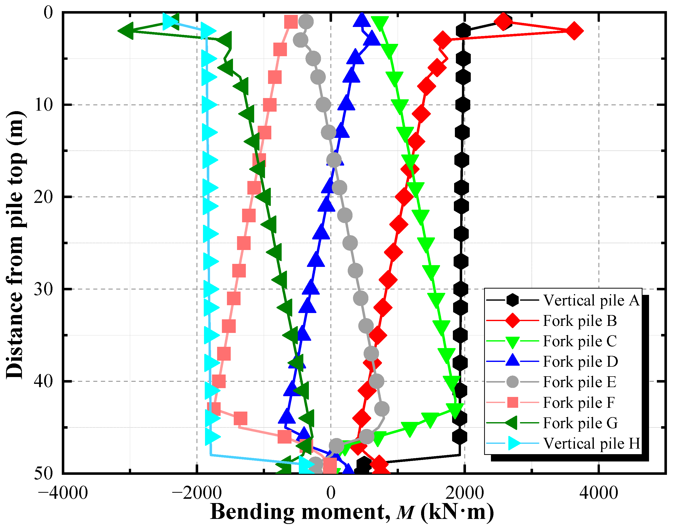
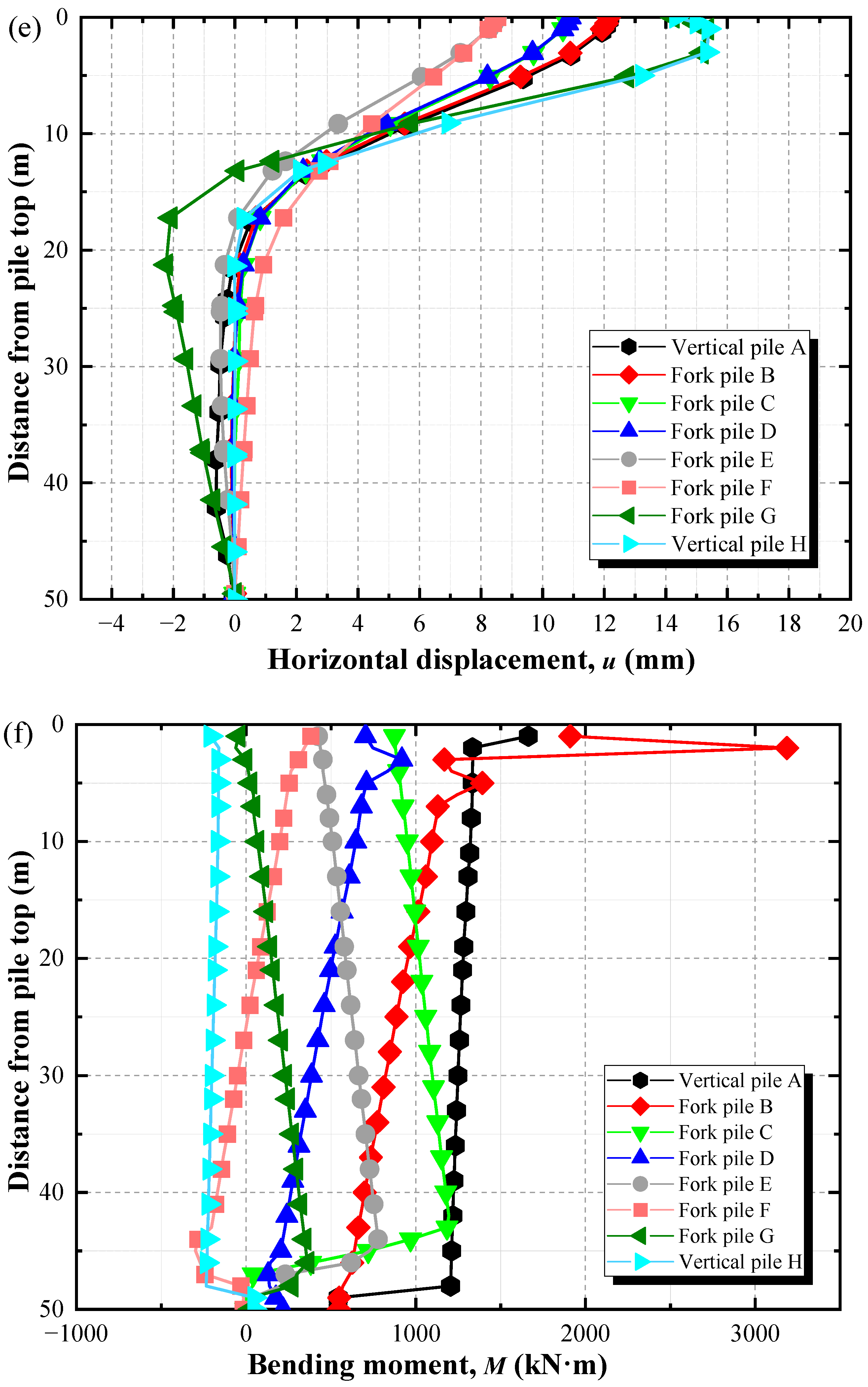
Based on the Morison equation, wave loads were applied to the steel pipe piles of the high-pile wharf through the distributed load subroutine DLOAD. The horizontal displacements of piles A, B, G, and H were significantly larger than those of the four middle cross piles. The bending moments of the vertical piles were more uniform compared to those of the batter piles, while piles B and F exhibited distinct zones of abrupt bending moment change. The maximum displacement and maximum bending moments of the wharf were both located within the wave load action zone.
3
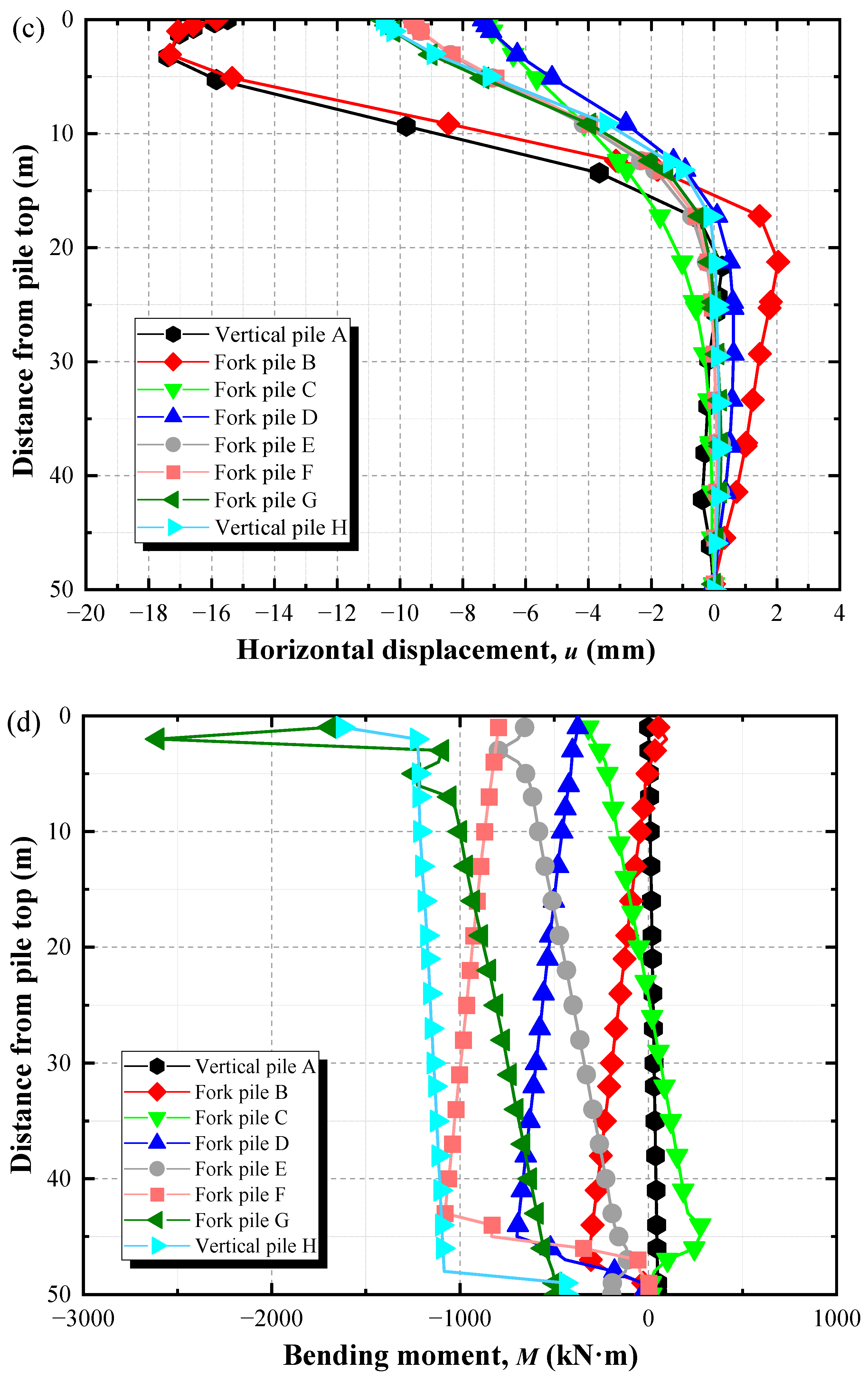
The impact of surface loads on the deformation and internal force responses of the wharf structure was evident. Under the global surface load, the horizontal displacements and bending moments of piles A and H were larger, while piles B and G showed distinct zones of abrupt bending moment change. Under local loading conditions, the horizontal displacement on the loaded side was larger, while the bending moment on the opposite side was relatively higher.
4
The coupling analysis of multiple external factors affecting the high-pile wharf reveals that surface loads have the greatest impact on the deformation and internal forces of the wharf. The soft foundation model and wave loads primarily affected the maximum displacement of the structure, with no significant impact on the maximum bending moment. Therefore, during the initial design of the wharf, the engineering characteristics of the deep soft soil foundation must be thoroughly considered. During the operational period of the wharf, the selection of the surface cargo placement is crucial, and special attention should be given to the areas affected by wave action, with focused prevention measures and monitoring.

Author Contributions

K.Y.: investigation, data curation, writing. C.C.: validation, software. R.B.: formal analysis, supervision. H.M.: methodology, conceptualization, funding acquisition. All authors have read and agreed to the published version of the manuscript.

Funding

This research was funded by the National Key Research and Development Program of China grant number No. 2023YFB2604200 And The APC was funded by School of Civil Engineering, Sun Yat-sen University & Southern Marine Science and Engineering Guangdong Laboratory (Zhuhai).

Data Availability Statement

The data reported in this article are available from the corresponding author upon request.

Acknowledgments

The authors would like to acknowledge the support received from The National Key Research and Development Program of China (No. 2023YFB2604200).

Conflicts of Interest

The authors declare no conflicts of interest.

References

  1. Cheng, Z.; Cong, S.; Cheng, Z. Recent Advances in Composite Caisson–Pile Foundation. Mar. Georesour. Geotechnol. 2025, 1–14. [Google Scholar] [CrossRef]
  2. Hu, Y.; Wang, Q.; Zhu, R.; Li, C.; Wang, N. Real-Time Identification of Foundation Damage in High-Pile Wharves: Nonlinear Feature Change Point Analysis in Dynamic Characteristics under Wave Excitation. Measurement 2025, 243, 116365. [Google Scholar] [CrossRef]
  3. Zhou, J.; Zhang, R.; Gong, X.; Yu, J. Field Study on Uplift Bearing Capacity of Pre-Bored Grouted Planted Pile and Bored Pile in Deep Soft Soil. Ocean Eng. 2025, 322, 120477. [Google Scholar] [CrossRef]
  4. Wang, Y.; Zhang, S.; Ren, Y.; Qi, Z.; Yang, Q. Characterization of Engineering Properties of Deep-Water Soils in the South China Sea. Eng. Geol. 2023, 320, 107138. [Google Scholar] [CrossRef]
  5. Lin, Y.; Qin, H.; Guo, J.; Chen, J. Study on the Rheological Behavior of a Model Clay Sediment. J. Mar. Sci. Eng. 2021, 9, 81. [Google Scholar] [CrossRef]
  6. Han, Y.; Li, J. Study of Deformation Performance and Seismic Damage on Pile-Supported Wharf by Shaking Table Test. Integr. Ferroelectr. 2024, 240, 1298–1314. [Google Scholar] [CrossRef]
  7. Jingyu, R.E.N.; Kunpeng, W.; Chunyi, C.U.I.; Hailong, L.I.U.; Min, Z. Analysis of Force Deformation in Wharf Pile Foundation-Slope System under Siltation Conditions. Hydro-Sci. Eng. 2024, 5, 113–123. [Google Scholar]
  8. Wu, M.; Zheng, J.; Liu, Q.; Zheng, L.; Deng, T. Calculation Method of Flow Drag around a Pile in Soft Soil Considering Bingham Fluid Properties and Analysis of Single Pile Response. Ocean Eng. 2025, 317, 120031. [Google Scholar] [CrossRef]
  9. Li, B.; Chen, F.; Chen, L.; Fu, J.; Shan, Z.; Chen, J. The Engineering Characteristics of Uplift Piles in Soft Clay. J. Perform. Constr. Facil. 2025, 39, 6025002. [Google Scholar] [CrossRef]
  10. Tan, Y.; Fan, X. Statistical Analyses on a Database of Deep Excavations in Shanghai Soft Clays. In Databases for Data-Centric Geotechnics; CRC Press: Boca Raton, FL, USA, 2024; pp. 600–630. [Google Scholar]
  11. Peng, X.-B.; Ren, W.-J.; Li, T.-Q.; Xue, Y.-Y.; Tao, X.-S.; Xu, L.-Y. Seismic Response of Deep Soft Soil Sites with Varying Shear Wave Velocities. Front. Earth Sci. 2024, 12, 1488519. [Google Scholar] [CrossRef]
  12. Fu, X.; Li, J.; Liu, J.; Hu, Z.; Tang, C. Influence of Complex Hydraulic Environments on the Mechanical Properties of Pile-Soil Composite Foundation in the Coastal Soft Soil Area of Zhuhai. Buildings 2023, 13, 563. [Google Scholar] [CrossRef]
  13. Yan, Z.; Sun, X.P.; Yang, Z.X.; Fu, D.F. Lateral Bearing Performance of a Defective Pile-Supported Wharf with Batter Piles. J. Waterw. Port Coast. Ocean Eng. 2020, 146, 4020035. [Google Scholar] [CrossRef]
  14. Zhu, D.T. Hydrodynamic Characteristics of Offshore and Pile Breakwaters. Ocean Eng. 2015, 104, 257–265. [Google Scholar] [CrossRef]
  15. Zhang, D.; Zhang, L.; Liu, X. Deformation Response of a High-Pile Wharf Foundation the Process of Slope Siltation. J. Water Resour. Water Eng. 2022, 33, 159–163. [Google Scholar]
  16. Yi, J.H.; Kim, S.B.; Yoon, G.L.; Andersen, L.V. Natural Frequency of Bottom-Fixed Offshore Wind Turbines Considering Pile-Soil-Interaction with Material Uncertainties and Scouring Depth. Wind Struct. 2015, 21, 625–639. [Google Scholar] [CrossRef]
  17. Zhao, M.; Wu, G.; Wang, K. Comparative Analysis of Dynamic Response of Damaged Wharf Frame Structure under the Combined Action of Ship Collision Load and Other Static Loads. Buildings 2022, 12, 1131. [Google Scholar] [CrossRef]
  18. Zhao, J.; Cui, C.; Zhang, P.; Wang, K.; Zhao, M. Parameter Sensitivity Analysis of the Seismic Response of a Piled Wharf Structure. Buildings 2023, 13, 349. [Google Scholar] [CrossRef]
  19. Wang, Z.; Wang, W.; Qiu, W.; Jiang, M. Experimental Study on Wave-Induced Loads and Nonlinear Effects for Pier-Pile Group Foundations of Sea-Crossing Bridges: Wave Slamming and Suction Effect. Coast. Eng. 2024, 192, 104567. [Google Scholar] [CrossRef]
  20. Li, R.; Huo, Y. Three-Dimensional Finite Element Analysis of Pile-Supported Wharf Considering Sediment Deposition. Port Waterw. Eng. 2016, 10, 95–99. [Google Scholar]
  21. He, L.; Wang, Y.; Li, S.; Wang, Z. Practical Method and Application Study for Predicting Cyclic Accumulative Deformations of the Saturated Soft Clay. J. Mt. Sci. 2017, 14, 2348–2358. [Google Scholar] [CrossRef]
  22. Xie, L.; Su, L.; Wan, H.-P.; Wang, J.; Bi, J.; Ling, X. Experimental Study on Dynamic Response of Pile-Supported Wharf under Wave and Ship Berthing Collision. Appl. Ocean Res. 2023, 135, 103561. [Google Scholar] [CrossRef]
  23. Xie, Y.; Liu, C.; Gao, S.; Tang, J.; Chen, Y. Lateral Load Bearing Capacity of Offshore High-Piled Wharf with Batter Piles. Ocean Eng. 2017, 142, 377–387. [Google Scholar] [CrossRef]
  24. de Macêdo Wahrhaftig, A.; Plevris, V.; Mohamad, B.A.; Pereira, D.L. Minimum Design Bending Moment for Systems of Equivalent Stiffness. Structures 2023, 57, 105224. [Google Scholar] [CrossRef]
  25. Systèmes, D. Abaqus 6.10: Analysis User’s Manual; Dassault Systèmes Simulia Corp.: Providence, RI, USA, 2010. [Google Scholar]
  26. Darendeli, M.B. Development of a New Family of Normalized Modulus Reduction and Material Damping Curves; The University of Texas at Austin: Austin, TX, USA, 2001; ISBN 0-493-36697-0. [Google Scholar]
  27. Ju, L.; Xu, R.; Zhu, J.; Tao, Y.; Yu, T. An Elastoplastic Model with Egg-Shaped Yield Surface for Coastal Soft Clay. Appl. Ocean Res. 2024, 146, 103975. [Google Scholar] [CrossRef]
  28. Chen, G.; Wang, Y.; Zhao, D.; Zhao, K.; Yang, J. A New Effective Stress Method for Nonlinear Site Response Analyses. Earthq. Eng. Struct. Dyn. 2021, 50, 1595–1611. [Google Scholar] [CrossRef]
  29. Cheng, X.; Li, M.; Ma, C.; El Naggar, M.H.; Wang, P.; Sun, X. Dynamic Analysis of Tripod Pile Foundation in Clays for Offshore Wind Turbines. Ocean Eng. 2023, 287, 115832. [Google Scholar] [CrossRef]
  30. Ma, K.; Gao, Z.; Wang, J.; Zhang, Y.; Zong, M.; Wu, W.; Mei, G. Nonlinear Consolidation Finite Element Analysis of a Layered Soft Soil Foundation under Multistage Loading Based on the Continuous Drainage Boundary. Comput. Geotech. 2024, 169, 106220. [Google Scholar] [CrossRef]
  31. Wang, Y.; Fu, H.; Cai, Y.; Yu, X.; Zhao, J. Seismic Subsidence of Soft Subgrade with Considering Principal Stress Rotation. Int. J. Civ. Eng. 2022, 20, 827–837. [Google Scholar] [CrossRef]
  32. Chanda, D.; Saha, R.; Haldar, S. Behaviour of Piled Raft Foundation in Sand Subjected to Combined V-M-H Loading. Ocean Eng. 2020, 216, 107596. [Google Scholar] [CrossRef]
  33. Morison, J.R.; Johnson, J.W.; Schaaf, S.A. The force exerted by surface waves on piles. J. Pet. Technol. 1950, 2, 149–154. [Google Scholar] [CrossRef]
  34. Reeve, D.; Chadwick, A.; Fleming, C. Coastal Engineering: Processes, Theory and Design Practice; CRC Press: Boca Raton, FL, USA, 2018; ISBN 1-351-16552-6. [Google Scholar]
  35. Zhang, H.C.; Li, G.; Geng, J.; Zhao, X.L.; Liu, S.X.; Li, J.X. Wave Force Characteristics of Fixed Photovoltaic Pile Structures under Multi-Directional Irregular Waves. In Innovations in Renewable Energies Offshore; CRC Press: Boca Raton, FL, USA, 2024; pp. 139–145. [Google Scholar]
Figure 1. Cross-sectional diagram of the high-piled wharf (unit: m).
Buildings 15 02379 g001
Figure 2. Finite element model of the high-pile wharf.
Buildings 15 02379 g002
Figure 3. Variation of deep soft soil dynamic elastic modulus with strain under different confining pressures.
Buildings 15 02379 g003
Figure 4. Stiffness degradation curves of deep soft soil.
Buildings 15 02379 g004
Figure 5. Displacement–loading coefficient curves of different soil constitutive models.
Buildings 15 02379 g005
Figure 6. Schematic diagram of wave force calculation on cylindrical piles.
Buildings 15 02379 g006
Figure 7. Horizontal displacement distribution of pile foundation under standard design uniform load and wave action.
Buildings 15 02379 g007
Figure 8. Bending moment distribution of pile foundation under standard design uniform load and wave action.
Buildings 15 02379 g008
Figure 9. Distributions of horizontal displacement and bending moment of piles under different surface load distributions: (a) displacement diagram under global uniform load; (b) bending moment diagram under global uniform load; (c) displacement distribution under load on the front bearing platform; (d) bending moment diagram under the load on the front bearing platform; (e) displacement diagram under the load on the back bearing platform.; (f) displacement diagram under the load on the back bearing platform.
Buildings 15 02379 g009aBuildings 15 02379 g009bBuildings 15 02379 g009c
Table 1. Key parameters of the high-pile wharf model under multi-factor coupling at the 95% confidence level.
Working ConditionMaximum Horizontal Displacement
umax (mm)
Maximum Bending Moment of Pile B MBmax (kN·m)Maximum Bending Moment of Pile G MGmax (kN·m)
MC + UF[16.79, 16.92][303.9, 311.5][2600.7, 2612.6]
MC + UB[14.89, 15.23][3196.0, 3209.3][370.7, 376.6]
MC + UG[8.59, 8.66][3637.5, 3645.2][3015.0, 3039.7]
MC + Wave + UF[16.89, 17.09][302.1, 305.9][2621.1, 2623.9]
MC + Wave + UB[16.97, 17.15][3215.1, 3217.9][383.1, 386.9]
MC + Wave + UG[9.48, 9.63][3660.3, 3673.7][3040.0, 3047.3]
VM + UF[17.35, 17.47][230.8, 235.8][2605.3, 2615.7]
VM + UB[15.33, 15.50][3181.7, 3192.3][358.9, 366.1]
VM + UG[8.56, 8.76][3599.0, 3617.4][3010.1, 3029.9]
VM + Wave + UF[17.01, 17.22][300.9, 310.1][2617.6, 2626.4]
VM + Wave + UB[17.17, 17.32][3218.6, 3227.4][379.6, 390.4]
VM + Wave + UG[9.78, 9.88][3626.1, 3647.9][3015.9, 3036.1]
VM: viscoelasticity model; MC: Mohr–Coulomb model; UF: uniformly distributed load on the front bearing platform; UB: uniformly distributed load on the back bearing platform; UG: global uniform load.
Disclaimer/Publisher’s Note: The statements, opinions and data contained in all publications are solely those of the individual author(s) and contributor(s) and not of MDPI and/or the editor(s). MDPI and/or the editor(s) disclaim responsibility for any injury to people or property resulting from any ideas, methods, instructions or products referred to in the content.

