Article

Non-Linear Behaviour and Analysis of Innovative Suspension Steel Roof Structures

by
Algirdas Juozapaitis
1,
Alfonsas Daniūnas
1,* and
Leonas Ustinovichius
2
1
Department of Steel and Composite Structures, Vilnius Gediminas Technical University—VILNIUS TECH, Saulėtekio al. 11, 10223 Vilnius, Lithuania
2
Institute of Sustainable Construction, Vilnius Gediminas Technical University—VILNIUS TECH, Saulėtekio al. 11, 10223 Vilnius, Lithuania
*
Author to whom correspondence should be addressed.
Buildings 2024, 14(3), 661; https://doi.org/10.3390/buildings14030661
Submission received: 19 January 2024 / Revised: 19 February 2024 / Accepted: 24 February 2024 / Published: 1 March 2024
(This article belongs to the Special Issue Non-linear Behavior and Design of Steel Structures)

Abstract

:
Suspension structures are one of the most effective roof load-bearing structures for medium to long spans. Their shape under symmetric loads is usually a square parabola or a curve close to it. The biggest drawback of such structures is their increased deformability under asymmetric loads. So-called rigid cables are used to solve this problem. However, the production of such rigid cables with a curvilinear shape is complicated, and their maintenance also has drawbacks due to the above-mentioned shape. To avoid these shortcomings, straight-line suspension structures have been used. This paper proposes a new form of combined suspension roof structures consisting of main load-bearing straight suspension elements supported by cable struts. For the main suspension elements, the bending stiffness is accepted, taking into account the operational requirements of the structure. This article analyses the behaviour of such a combined suspension structural system in symmetric conditions with an innovative approach. The arrangements of this system are discussed. The calculation of the forces and displacements of this structure and its elements is presented, taking into account the geometrical nonlinear behaviour. The distribution of the forces in the rigid elements and node displacements of the structure are discussed. The proposed new form of a combined cable-supported roof structure was shown to be more effective in terms of weight than the standard parabolic-shaped suspension structure.

1. Introduction

Suspension structures, due to their efficiency and appealing architectural appearance, are widely used as the primary load-bearing structures in buildings of various purposes [1,2]. These structures are used in various forms of roof structures and suspension bridges [3,4,5]. These structures bear transverse loads by tension, thus covering not only medium but also long spans [6,7,8]. Suspension steel structures have been used for decades on the roofs of modern buildings [9,10]. They can take various forms, from flat parabolic outlines to double curved cable structures or a cable truss [11,12,13]. New and rational, from the point of view of material consumption, the hierarchical cable roofing structure is examined in [14]. Spiral wire ropes are most commonly used for such suspension steel structures. The form of the suspension roof, and consequently the cables, is chosen as the parabolic shape defined as the primary equilibrium form when subjected to uniformly distributed loads across the span length [7,15,16]. An original analysis of the shape of suspension structures in assessing the stages of construction was carried out in [17]. Suspension structures also have disadvantages, mainly related to asymmetrical loading, where kinematic origin displacements occur [18,19,20]. Additionally, the modulus of elasticity of the spiral wire ropes is lower than that of structural steel, which increases their deformability [21,22]. It should be noted that the cylindrical surface of such suspension structures complicates their construction, operation, and maintenance, especially under wind loads [23,24,25]. Dynamic loads also have a great influence on the behaviour of suspended structures [26,27]. Spiral wire cables are vulnerable to corrosion [28,29]. To stabilize the initial surface of such suspension roofs, heavy concrete panels or pre-tensioning of the cable’s structures are often applied, which significantly increases the axial forces of these bearing suspension structures, and in some cases, the structural height of such suspension structures [10,11].
Special methods to stabilise the shape of the suspension roof are used when bending stiff cables are applied [30,31,32]. Two-level suspended rigid cables have been studied in [33]. These suspension structures bear transverse loads not only by tension but also by bending, and they are sometimes referred to as “rigid cables” [34]. Such cables are also proposed for use in suspension bridges [35,36]. These “rigid” suspension structures allow the use of lightweight roof panels, which reduces the tensile cable forces and the weight of the anchor structures. It is worth noting that such “rigid” suspension structures do not require complex intermediate and anchoring joints or the often-used pretensioning [36,37]. Their cross-sections are designed from regular structural steel, and conventional rolled or welded cross-sections are applied [38,39]. Therefore, the production and assembly joints of such “rigid” suspension structures are significantly simpler than those made from spiral wires [40,41]. It is essential to point out that these “rigid” suspension structures are often designed as cables in a parabolic form [30,31,32]. Hence, the curved shape of these “rigid cables” also complicates their production, construction, and operation.
Recently, suspension structures composed of straight elements with bending stiffness have started to be applied to suspension roof structures [42]. The main drawback of such “rigid” suspension structures is their unsuitable shape when they are subjected to symmetrical uniform loads. The result is significant displacements and bending moments of its straight “rigid” suspension elements [42]. Therefore, these “rigid” elements are flexibly interconnected, forming a tri-hinged suspension structure. Compared to parabolic two-hinged suspension structures, their advantage is less sensitivity to always existing displacements of the support structures.
Numerous studies have been dedicated to different research tasks related to cable structures, for example [43,44,45,46,47]. To improve the accuracy of numerical calculations, new finite elements are being created for the analysis of suspended structures [45,46]. Original methods are being developed to calculate the tensile forces of prestressed suspension structures [47]. Experimental studies of the original composite suspended structure from two straight elements were carried out [48]. The vibration analysis of a large-span cable was even evaluated in [49]. Many works were devoted to the refined calculation of cables [50,51,52]. The behaviour and calculations of cables or their systems arranged in space were also analysed [53,54]. Theoretical and experimental studies of a levy hinged-beam cable dome were conducted [55]. In certain cases, when analysing the behaviour of cables, their actual bending stiffness was evaluated, causing local relatively small bending moments at their joints [56,57]. Interesting studies have been prepared, which present methods for analysing structural cables in bending and wire sliding problems [58,59,60]. It is essential to acknowledge that there are not many publications dedicated to the behaviour analysis of so-called “rigid cables”. Mostly, the behaviour of the parabolic shaped “rigid cables” is studied [34,61,62]. Known works are dedicated to the arrangement and calculation of suspension bridges with parabolic shaped rigid cables [36]. When considering suspension bridges, it is necessary to mention original publications dedicated to the analysis of bridge behaviour under complex operational conditions [63,64]. Among them, a work focused on the analysis of stress-ribbon bridges and the design of rational cross-sections should be highlighted [36]. It is crucial to note that there are few works dedicated to calculating a suspension system from straight “rigid” elements [42].
A review showed that only a few works are devoted to suspended structures made of straight elements. The aim of this work was to increase the efficiency of steel suspension roof structures and to create an innovative suspended truss system from straight “rigid” elements, which does not have the operational disadvantages of parabolic-shaped structures. It is also necessary to first analyse the behaviour of such a new suspension system under symmetrical loads.
The calculation of the forces and displacements of these suspension systems and their elements is presented, taking into account their geometrical nonlinear behaviour. The calculation method of such a system is presented using the concept of fictitious displacement, which allows to reduce the number of iterations of the iterative calculation.
It was shown, by applying a numerical experiment, that the proposed new form of the suspension roof structural system is more efficient than a two straight elements suspension structure.

2. Innovative Suspension Roof System

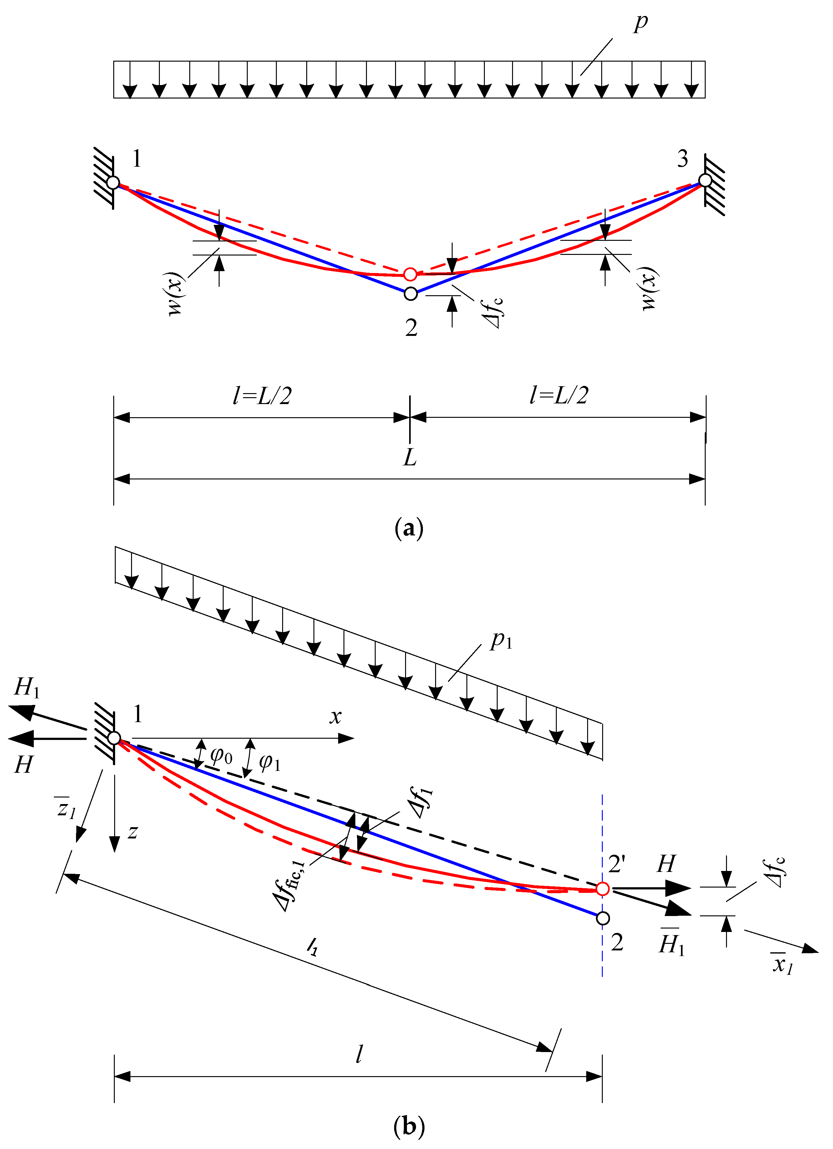
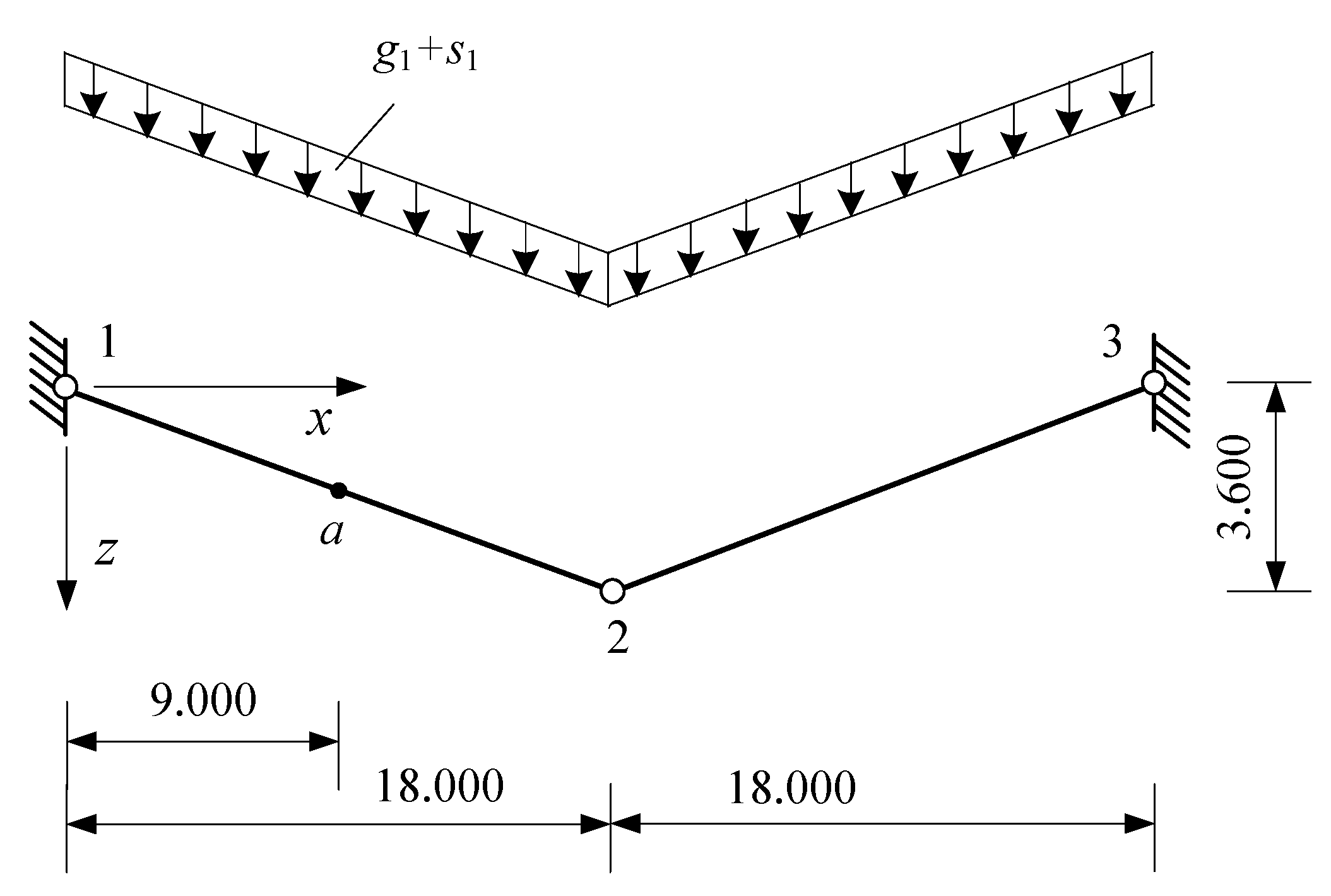
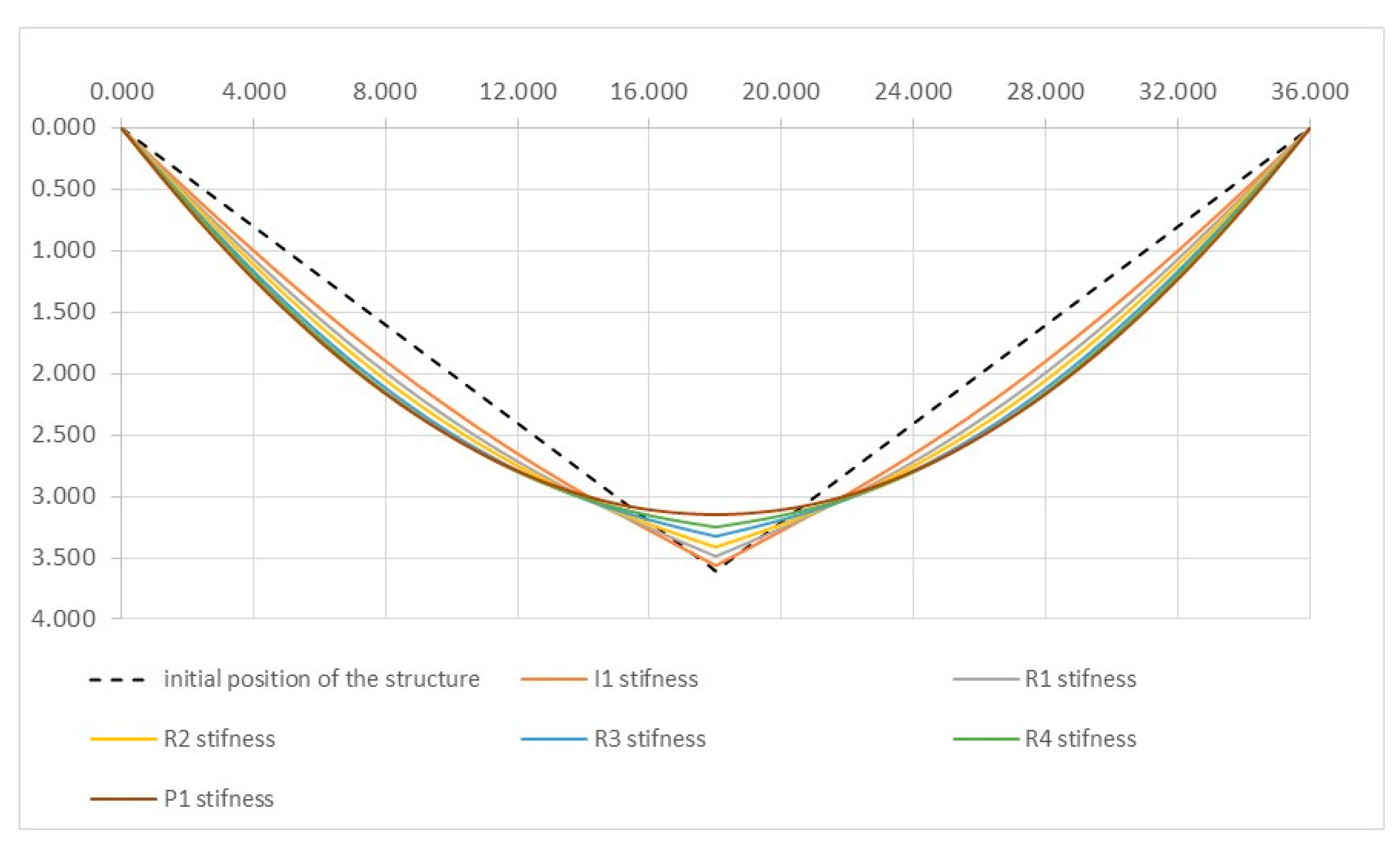
2.1. Analysis of Suspension System with Two Straight “Rigid” Elements

First, let us examine a suspension steel structure prototype composed of two straight elements that have bending stiffness. It should be noted that there are only a few studies dedicated to the analysis of such suspension structures. As mentioned earlier, this structure is subjected to significant displacements under symmetrical uniform loads in Figure 1a. When the suspension structure is subjected to uniformly distributed symmetric loads, it is possible to analyse half of this symmetrical structure, see Figure 1b. Under the influence of the load, the straight suspension “rigid” element will deflect by f 1 , e l and its node “2” will have a displacement of f c . Tensile force H 1 and bending moment M 1 x 1 will occur in it. The primary dependent unknowns are f c , f 1 , e l , and H 1 . To simplify the calculations and reduce the number of iterations, we will apply the concept of a fictitious displacement f f i c , 1 , which means that it is possible to formulate an equilibrium equation for the suspension element with bending stiffness in a way similar to a cable (disregarding the bending moment acting on it), but with the tensile force value being the same as that of a rigid suspension element:
f f i c , 1 = p l 1 2 8 H 1 .
This equation not only simplifies the solutions but also allows the final formulas to be written in a manner analogous to a flexible suspension structure.
Then, the differential equilibrium equation for this straight suspension “rigid” steel element will be as follows:
M p x H 1 · w 1 x + w 1 x · E I = 0 .
The solution for the actual displacement w 1 x with respect to the coordinate origin (when the coordinate origin is at point “1”) will be as follows:
w 1 x = f f i c 8 k 1 l 2 c h k 1 x + 1 c h k 1 l s h k 1 x s h k 1 l 1 + 4 x l 4 x 2 l 2 + f c x l ,
where k 1 l = H 1 l 2 E I c o s 3 φ 1 is the slenderness parameter of the straight suspension element and M p x is the moment induced by external loads.
Using the compatibility equation of the deformations of the suspension element (4):
s 0 + s e l , 1 = s 1
Taking into account (1), we will obtain an expression to calculate the fictitious displacement of the “rigid” suspension element.
f f i c = 3     p * l 4 64   E A ·   Φ k 1 l · ɳ   c o s 5 φ   3 ,
here
Φ k 1 l = 1 24 k 1 l 2 1 2 k 1 l t h k 1 l 2 + 6 s h k 1 l k 1 l k 1 l 3 c h 2 k 1 l / 2
There is a function that evaluates the influence of the flexural stiffness parameter k 1 l (and therefore EI) on its displacements. s 0 = l c o s φ ; s e l , 1 = H 1   l E A   c o s φ 0   c o s φ 1   is the elastic elongation of the element and s 1 = l + 0.5 0 l w 1 x 2 d x . is the length of the element after deformation.
ɳ = 1 + 3 8 l f f i c 2 c o s φ 1 Φ k 1 l l c o s φ 1 l c o s φ 0
The η assesses the influence of the central hinge displacement on the values of f f i c . It is important to note that expression (5) is analogous to the formula for calculating displacements in a flexible steel string, with additional consideration of the impact of flexural stiffness EI on displacements. The fictitious displacement f f i c is computed through iterations, starting with an initial tensile force value of H 1 . Initially, it can also be assumed to be the deflection of the string:
H 01 = p 2 l 2 E A 24 c o s 5 φ 1 3 .
It is essential to mention that there is one more additional unknown, which is the vertical displacement f c of the central node. It also defines the angle ϕ. From the equilibrium equation at the central node, we obtain an expression that relates the dependent variables f c or f f i c , 1 :
f f i c , 1 = 0.25 f 0 f c c o s φ 1 .
Iterations using Formulas (1) and (5) can be terminated when the condition is satisfied:
s 1 s 0 s e l , 1 .
When the value of the fictitious displacement f f i c , 1 is known, it is possible to determine the actual displacement f 1 , e l of the straight steel element and the bending moment acting on this element based on Formula (3):
M 1 x = E I · w 1 x = E I · f f i c   8   c o s φ 1 l 2 c h   k 1 x 1 c h ( k 1   l 2 ) 1
It is essential to mention that when subjected to a uniformly distributed load, the maximum value of the bending moment for a straight suspension element occurs at its midpoint, i.e., when x 1 0 (assuming the coordinate origin is taken at the center of the straight element).

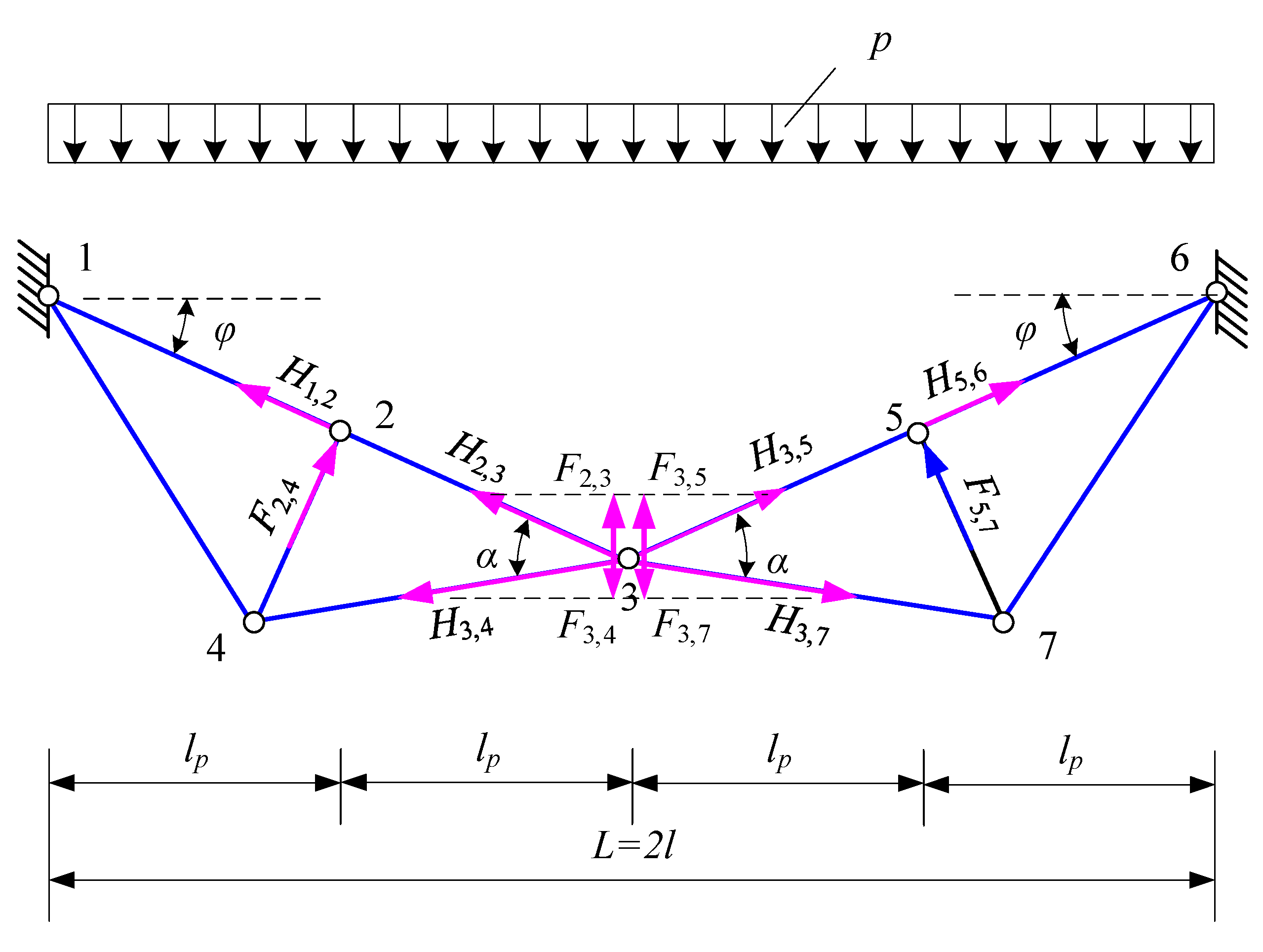
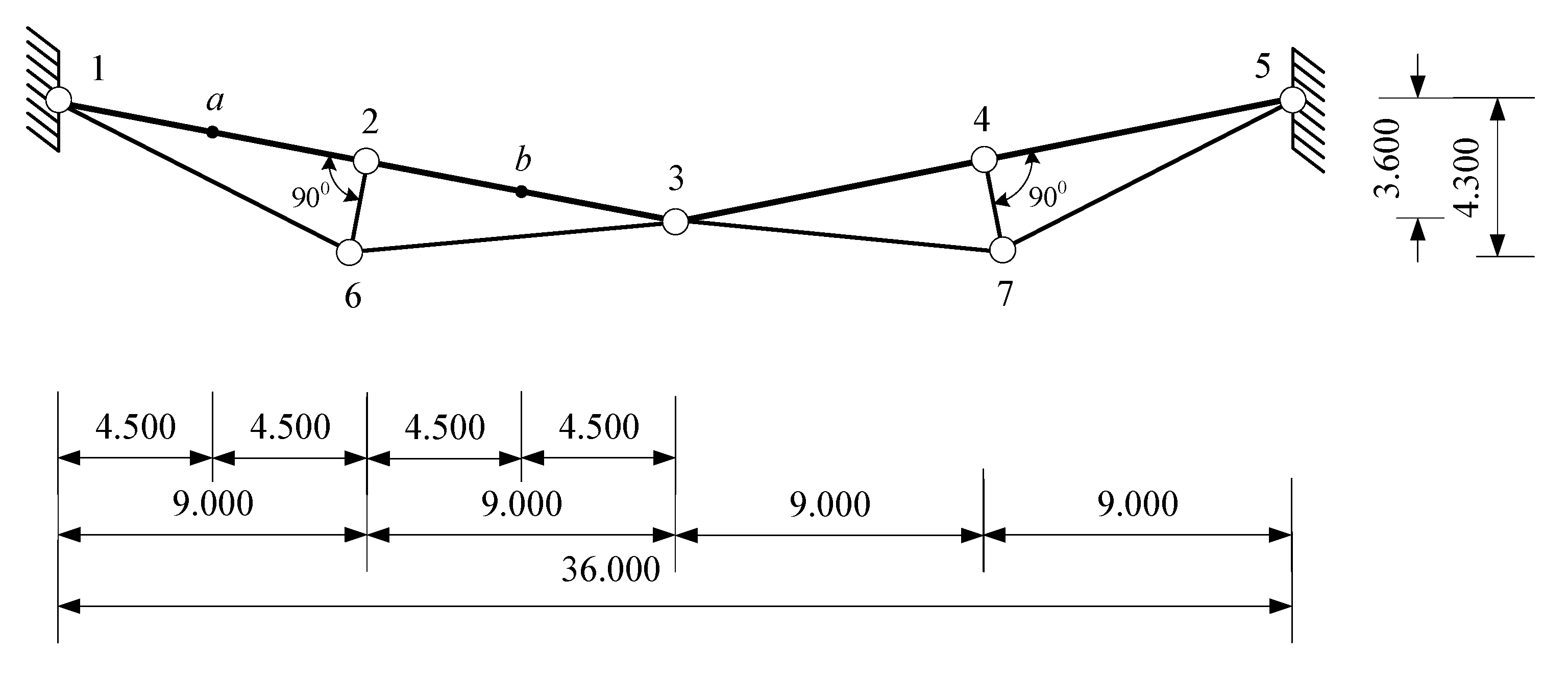
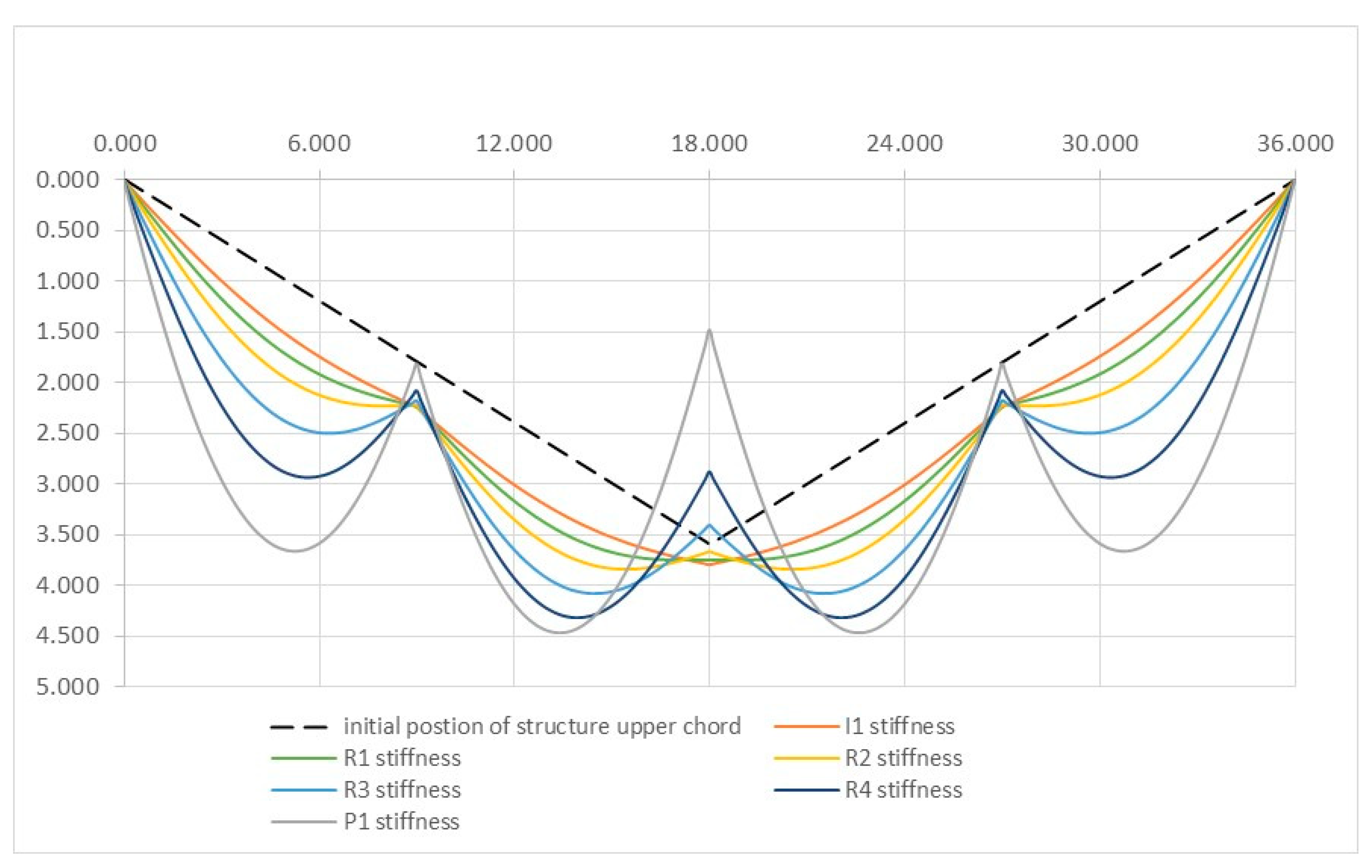
2.2. Parameters of Innovative Suspension Cable-Strut Systems of Straight Elements

The prototype of the suspension cable-strut system could be two straight steel elements, where these elements have flexural stiffness ( E I 0 ); see Figure 1. As mentioned above, from a practical manufacturing and operational point of view, the two-element structure is not an unadaptive shape when subjected to a uniformly distributed load. This uniformly distributed load changes the original shape of the elements and the resulting displacements are f f i c , 1 and f f i c , 2 , and the relevant bending moments, see Equations (3), (8) and (10).
If we assume that the elements of this structure are absolutely flexible ( E I = 0 ), the fictitious displacement of the straight elements will be equal to their actual displacement ( f f i c = f e l * ). This displacement is calculated along the line connecting the support and the central hinge (see Figure 1). In this case, the function Φ k 1 l = 1 and the elastic deformation of the flexible suspension element at its midpoint will take the following expression:
f e l = 3 p * l 4 64 E A · ɳ c o s 5 φ 3 ,
here
ɳ = 1 + 3 8 l f e l 2   c o s φ 1   l c o s φ 1 l c o s φ 0 .
The displacement of such a flexible element at any of its points will be calculated as follows:
w 1 x = f e l 4 x l 4 x 2 l 2 + f c x l .
Expressions (11) and (12) clearly indicate that in this case, the displacements of suspension steel structure elements will be significant, and often they may no longer satisfy the stiffness conditions ( w 1 x > w l i m ) .
Therefore, to maintain the initial shape of elements of such a structure, as previously mentioned, it is necessary to provide flexural stiffness (EI > 0), and the values should be chosen based on the applied loads and the stiffness conditions of the limit state. It must be acknowledged that this method is not always highly effective and, under certain operating conditions, may require considerable steel expenses. Increasing the bending stiffness is not always effective as it requires higher steel consumption.
To achieve a greater stabilisation effect of the initial shape, an innovative suspension steel structure can be applied, where the straight hanger elements are additionally “supported” by a cable strut (see Figure 2).
It should be noted that in this structure, the upper hord consists of four suspension elements (1-2, 2-3, 3-5, 5-6) with flexural stiffness ( E I 0 ) connected together flexibly (see Figure 2). The elements of the lower hord are also flexibly connected. In this structural suspension system, a crucial geometric parameter is the height of the strut h 2,4 or the angle α, which depends on it to connect the lower hord to the upper hord; see Figure 2 and Figure 3. By selecting the height of the strut h 2,4 (or the angle α) properly, it is possible to restrict the vertical displacements of the central hinge.
The behaviour of such a suspension steel structure is under the influence of a symmetric uniformly distributed load p (see Figure 2). For the initial selection of parameters, assume that the elements of this structure are E I = 0 ,   E A . The upper hord tensile elements (1-2, 2-3, 3-5, 5-6) will attempt to approach the shape of a quadratic parabola under the influence of the load, meaning that the central node will move upward. As mentioned above, the displacements of this structure will be stabilized when the vertical displacements of the central hinge are constrained (they it will not allow it to move upward). These displacements of the central hinge are restricted by elements “3-4” and “3-7” of the lower hord.
Analysing half of the symmetric structure and the forces acting on its central hinge, it can be noted that the lower hord limits the upward displacement of the central hinge only when the angle α φ . From the equilibrium equation of the central node, we derive the condition to stabilise the vertical displacement of this node, see Figure 2.
F 3,4 F 2,3 ,
here F 3,4 = H 3,4   ·   t g α φ is the vertical component of the lower hord tensile forces and F 2,3 = 0.25   p l H 2,3   · t g   φ is the vertical component of the upper hord tensile forces.
Solving Equation (13) considering the expressions for H 3,4   and H 2,3 , we will obtain the required height of the strut:
h 2,4 0.5 f 0 1 0.125 f 0 f 2 k + c o s φ ,
here f 2 k = f 0 ( 1 0.75 ) is the kinematic displacement of the element “2-3”.
As evident from Equation (14), the required height of the strut depends on sag f 0 and the kinematic displacement of the upper hord f 2 k . It should be noted that Formula (14) is approximate and considering the deformations of the elastic element “2-3”, the value of the strut height can be adjusted. Until the value of f 2 k is known, Condition (14) can be expressed in such a way:
h 2,4 0.5 f 0 1 + c o s φ .
The maximum height of the strut h 2,4 , taking the arrangement requirements into account, should not exceed the initial system sag   h 2,4 f 0 .

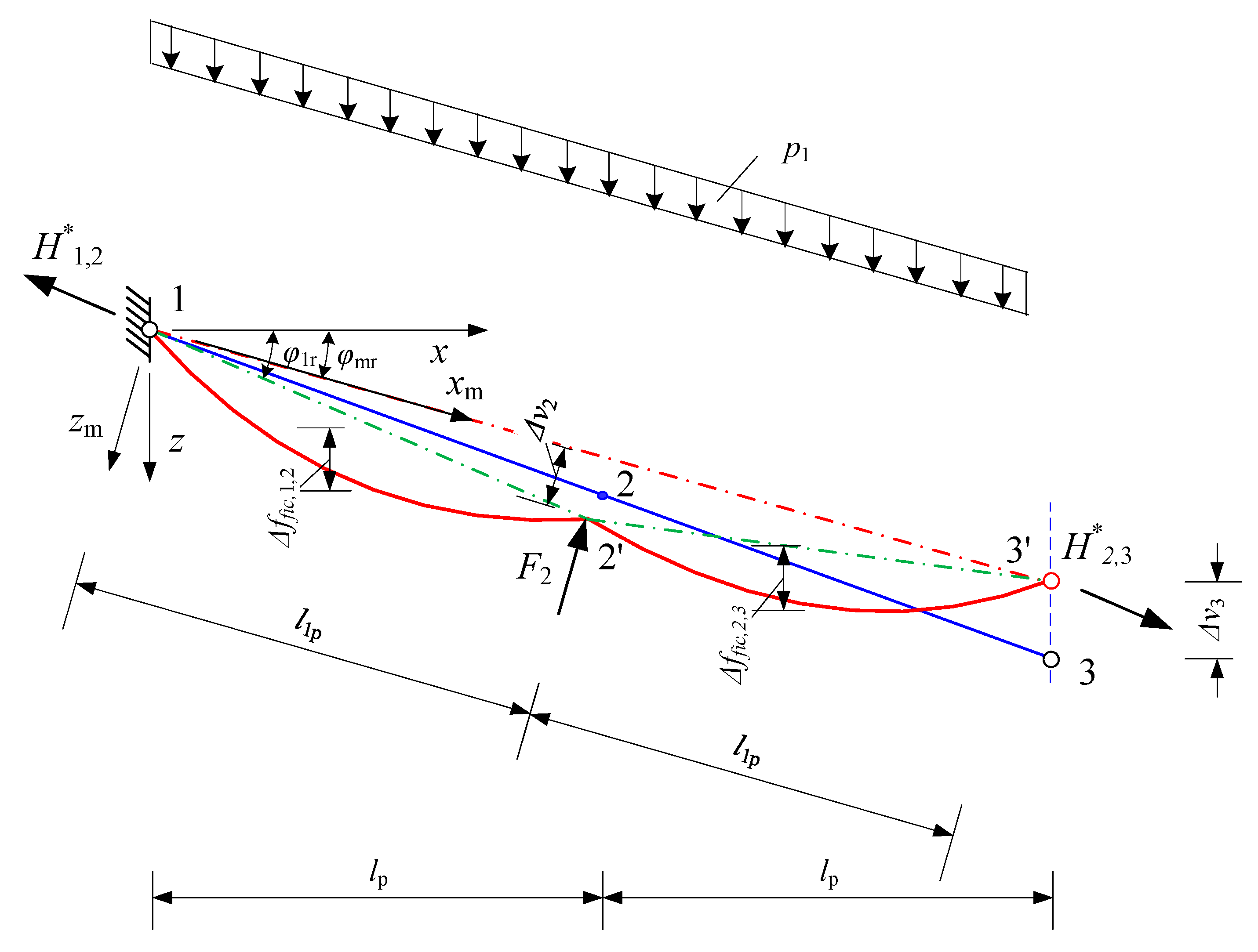
2.3. Non-Linear Analysis of Innovative Suspension Single-Level Cable-Strut System

The calculation of innovative suspension steel structures composed of both straight elements and a curved lower hord is more complex than for structures made of two straight elements or the traditional parabolic cables previously discussed. Therefore, this innovative suspension structure is divided into an upper hord, consisting of four straight tensile elements with flexural stiffness, and a lower strutted hord, composed of straight but flexible elements (see Figure 4). When subjected to a symmetric load, it is possible to analyse half of this symmetric system in Figure 3. The central hinge “3” will move upward by v 3 = f c , while the lower hord node “4” will move both vertically and horizontally by v 4 and h 4 . In the calculations, it is assumed that the strut “2-4” does not deform.
The upper hord node “2” will move vertically and horizontally in size v 2 and h 2 . Therefore, the main unknowns of the suspension system will be the displacements of nodes v 3 , v 4 , h 2 , and h 4 , and the deflections of the straight rigid elements in the upper hord, f 1,2 or f 2,3 (see Figure 3). Other dependent unknowns would be the tensile forces in the upper hord elements and the lower hord elements ( H 1,2 , H 2,3 and H 3,4 ) or the total tensile force H Ʃ at node “3”. The inclination angles of the upper hord elements “1-2” and “2-3” after deformation would be φ 1 or φ 2 as shown in Figure 3. We assume that the displacement of node “2” along the axis of the strut, denoted as f 2 m , is the same as the displacement f 4 in the same direction as the lower hord. It is essential to note that the displacements and forces of the upper hord elements depend on the displacements and forces of the lower hord. Therefore, we will analyse separately the behavior of the upper hord and the lower hord.

2.3.1. Non-linear Analysis of Upper Hord Elements

The design scheme for the upper hord under symmetric loading is presented in Figure 4. Applying the concept of fictitious displacement mentioned before for the calculation of the upper hord elements “1-2” and “2-3” would be analogous to the calculation of elements in a two-element suspension steel structure. Additionally, it is essential to assess the interaction between the two straight elements “1-2” and “2-3” at node “2”.
Using local coordinates x 1 ,   z 1 and decomposing the applied load p into loads perpendicular to the line “1-2-3” p v and horizontal to the line p h , we will obtain the equilibrium condition for the tensile forces at node “2”:
H 1,2 * H 2,3 * + p h · l p 1 .
From Equation (16), it is evident that the tensile forces in elements “1-2” and “2-3” are not equal to each other due to the effect of the horizontal load p h It should be noted that the tensile forces H 1 and H 2 are calculated analogously to (1):
H 1,2 * = p v l p 1 2 8 f f i c , 1,2 * 2 ,
H 2,3 * = p v l p 2 2 8 f f i c , 2,3 * 2 .
The initial lengths of elements “1-2” and “2-3” are assumed to be equal. Taking into account the Expression (16), we can write the relationship between the fictitious displacements of the upper hord elements “1-2” and “2-3”:
f f i c , 2,3 = f f i c , 1,2 1 + 8 f f i c , 1,2 · t g φ m / l p .
Formula (19) shows that the fictitious displacements f f i c , 2,3 and f f i c , 1,2 are not equal to each other, which means that the tensile forces H 1,2 * and   H 2,3 * are also not equal, see Formulas (17) and (18). Iterative procedures become more complex in such cases. Therefore, we will apply the average fictitious displacement f f i c , m and the average tensile force H m :
f f i c , m 2 0.5 f f i c , 1,2 2 + f f i c , 2,3 2 ,
H m , u * 0.5 H 1,2 * + H 2,3 * .
Then, using the equation of deformation Compatibility (9), we obtain the expression for calculating the average fictitious displacement:
f f i c , m = 3 p l 4 64 E A · Φ m k m l · ɳ m · c o s 2 φ 0 3 ,
here
ɳ m = 1 + 3 · l 8 Φ m k m l ( f f i c , m ) 2 c o s φ m l c o s φ m l c o s φ 0 .
The iterative procedure of the forces and fictitious displacements ( H m and f f i c , m ) for the upper hord elements is performed analogously to the suspension structure, applying the equation of deformation Compatibility (9) and the dependency:
H m , u = p l p 2 8 f f i c , m .
When the values of H m , u and f f i c , m are calculated, the fictitious displacements of the upper hord elements “1-2” and “2-3” are determined using the following formulas:
f f i c , 1 = f f i c , m 2 1 + μ 2 0.5 ,
f f i c , 2 = f f i c , m 2 1 + 1 / μ 2 0.5 ,
here μ = H m + 0.5 p h l p H m 0.5 p h l p .
The axial force of the strut “2-4” is obtained as follows:
N c = F 2,4 = p l l cos φ m H 1 + H 2 f 2 m · c o s φ m / l p .
Alternatively, in a simplified manner:
N c = p l l cos φ m 1 0.25 f 2 m / f f i c , m .
Formula (26a) shows that the axial force in the strut is not constant and depends not only on the node “2” displacement v 2 = f 2 m , but also on the average fictitious displacement of the upper hord elements f f i c , m , and likewise on the fictitious displacements of elements “1-2” and “2-3” f f i c , 1,2 and f f i c , 2,3 .

2.3.2. Non-Linear Analysis of the Lower Hord

Let us also analyse half of the lower hord under symmetric loading; see Figure 5. As mentioned above, the overall node “3” of the lower hord can move upward by v c 3 = f c due to the influence of the upper hord elements, while the lower node “4” of the strut will move downward and horizontally by the values v 4 and h 4 . Part of the lower hord can be considered as a cable, consisting of two straight flexible elements. We will denote the displacement of this cable along the strut as f 4 . The tensile force at the central node “4” is denoted as H 3 .
It should be noted that the forces N 1,4 and N 3.4 of the lower hord elements, when the strut is perpendicular to the upper hord (or to the line connecting nodes “1” and “3”), will be equal to each other:
N 1,4 = H t , 1 2 + F v , 1 2 = H t , 3 2 + F v , 3 2 = N 3,4 ,
here H t , 1 = H m H ; H t , 3 = H m + H ;
The average tensile force acting along the line “1-3” is equal to:
H m , l = 0.125 F 2,4 L / f 2,4 + f 4 ,
and H = 0.5 F 2,4 · s i n φ m .
The support reactions at points “1” and “3” are obtained as follows:
F v , 1 = 0.5 F 2,4 c o s φ m + H 1 f 0 + v 3 0.5 L ,
F v , 3 = 0.5 F 2,4 c o s φ m H 3 f 0 + v 3 0.5 L .
The tensile force H 3 is obtained as follows:
H 3 = H m , l c o s φ m .
Formula (29) demonstrates the influence of the lower chord in the displacements of the central hinge.
Using Equations (27)–(29), we can derive the formula for axial forces:
N 1,4 = H m c o s φ m 1 + 16 f 2,4 + f 4 2 c o s φ m L 2 0.5 = N 3,4 = N t .
which indicates that the axial forces in elements “1-4” and “3-4” are equal to each other.
To calculate the lower hord elements, similarly to the upper hord elements, it is necessary to apply an analogous deformation compatibility equation as in (4). Given a relatively large length of the strut f 2,4 and aiming to avoid the usual simplifications that arise due to errors in well-known calculations for suspension structures [6,8,11], the formulas for the initial length s 0 and the length after deformation s 1 of the lower hord elements are written more accurately:
s 0 = L 2 4 c o s 2 φ m + 4 f 2,4 2 ,
s 1 = L 2 4 c o s 2 φ m + 4 f 2,4 + f 2 m 2 .
Then the deformation compatibility equation is written as follows:
2 s e l · s 0 = s 1 2 s 0 2 ,
here: s 1 2 s 0 2 = f 0 + f c 2 f 0 2 + 4 f 2,4 + f 2 m 2 f 2,4 2 .
Applying Formula (30), the left side of Equation (33) can be written:
2 s e l · s 0 N c L 3 1.5 16 E A f 2,4 2 + f 2 m 2 c o s 2 φ m c o s φ 0
here: 1.5 = 1 + 16 f 2 m ( c o s φ 0 L ) 2 .
When calculating the lower hord, an important parameter is the axial force acting on the strut N c = F 2,4 . It can be obtained from Equation (33):
N c = 64 f 2,4 + f 2 m E A c o s 2 φ 0 c o s φ m L 2 1.5 f 0 + f c 2 f 0 2 4 + f 2,4 + f 2 m 2 f 2,4 2 .
Equation (35) clearly shows that the axial force in the strut depends not only on the strut’s length f 2,4 and the displacement of node “2” f 2 m but also on the initial sag of the structure f 0 and the displacement of central node “3” f c . This dependence of these variables is evidently nonlinear. It is important to note that according to the assumption used, the displacement of node “2” is equal to the displacement of node “4” ( f 2 m = f 4 ).
The main unknown for the lower chord will be considered as the displacement f 2 m or f 4 . It depends not only on the elastic deformations of this hord, but also on the displacement of the central node f c . Therefore, we will divide this displacement into elastic and kinematic components:
f 4 = f 4 , e l + f 4 , k .
Kinematic displacements can be obtained using Equation (33), assuming that elastic deformations are equal to zero ( s 1 2 = s 0 2 ). In this case, the kinematic displacement is equal:
f 4 , k = f 2,4 2 + 0.25 f 0 + f c 2 f 0 2 f 2,4 .
Assuming that the kinematic displacements of the lower chord will primarily obtain an adjusted initial sag, taking into account f 2 m ,   k :
f 2,4 , k = f 2,4 + f 4 , k .
Then Formula (35) can be rewritten as follows:
N c = F 2,4 = 64 f 2,4 , k + f 4 , e l E A c o s 2 φ 0 c o s φ m L 2 1.5 2 f 2,4 , k · f 4 , e l + f 4 , e l 2 .
Formula (38) shows that the lower chord with the movable support “3” can be designed as a suspension structure with non-moving supports and an initial sag equal to f 2,4 , k . The axial force F 2,4 of the strut now does not depend on the total displacement but only on the elastic displacement f 4 , e l . Therefore, an approximate expression for the elastic displacement can be obtained using Formula (38):
f 4 , e l = f 0 1 0.25 f 4 , k / f f i c , m 1 + f 0 1 0.25 f 4 , k f f i c , m f 2,4 , k + 0.25 f 0 / f f i c , m ,
Here, f 0 = p   L 4   1.5   512   E A   f 2,4 , k   2 c o s 2 φ 0   is the displacement of a conditional elastic cable loaded with a load p.
Formula (39) allows calculating f 4 ,   e l directly without iterations when the fictitious displacement of the upper hord f f i c , m   is known. The error of this formula does not exceed 2%, significantly reducing the scope of iterative calculations.
Calculations for the lower chord are also performed iteratively, assuming a fixed value for the central node displacement f c .
It is recommended to choose the cross-sectional area A of the lower hord from the limit displacement condition f 4 f 4 , u applying Formulas (36), (37) and (39) and the strength of the steel applied to it f y from the strength condition ( N 1,4 / A ) f y .

2.3.3. Non-Linear Analysis of the Suspension Cable-Strut System

Analysis of the fully symmetrically loaded suspension cable-strut system is performed by combining the iterative procedure for the upper and lower hords. The general design scheme for this system is presented in Figure 3. The main unknowns, as mentioned earlier, are considered to be the displacement of the central node f c , the displacements of other nodes “2” and “4”, and the fictitious displacements of the upper hord’s straight elements f f i c , 1,2 , f f i c , 2,3 . Other dependent variables would be the tensile forces of the upper and lower hords: H 1,2 , H 2,3 or H 1,4 , and H 3,4 . The total tensile force of the structure is determined from the equilibrium condition of the central node:
Ʃ H = p L 2 8 f 0 + f c .
It should be noted that this formula is analogous to the formula used to calculate the tensile force in suspension structures (cables) and represents an additional condition in the iterative procedure of this system. The main condition for the convergence of the iterative procedure is:
H 2,3 * t g φ 2 p L 4 = F 2,4 2 c o s φ m H 3 ( f 0 + f c ) 0.5 L .
An additional convergence condition would be the projection of the upper and lower hord forces acting on the central node onto the horizontal axis.
H 2,3 * c o s φ 2 + H 3 = Ʃ H = p L 2 8 f 0 + f c .
After analysing the expressions of the variables involved in Formulas (41) and (42), it is evident that the iterative procedure can be quite complex. Therefore, this iterative procedure is conditionally divided into two main stages. In the first stage, with a fixed (chosen) value of the central hinge displacement f c , the displacements of the structural system nodes and the constituent elements are calculated. In the second stage, a gradual approach is used to determine the final value of f c that satisfies the equilibrium conditions of the central node (41) and (42). The general sequence of these two stages in the iterative procedure would be as follows:
(1)
An initial value of the central hinge vertical displacement f c is assumed;
(2)
Using Formulas (24), (25), and (23), the average fictitious displacement of the upper hord f f i c , m is calculated iteratively;
(3)
The kinematic displacement f 4 ,   k of the lower hord node “4” is calculated using Formula (37), the elastic displacement f 4 ,   e l by using Formula (36), and the total displacement f 4 is calculated using Formula (39);
(4)
The axial force of the strut F 2,4 is calculated using expression (38);
(5)
The tensile forces H m , l and N 1,4 in the lower hord are calculated using Formulas (27) and (30);
(6)
The displacement f f i c , 2 of the upper hord and the tensile force   H 2,3 * are calculated according to (20);
(7)
The convergence conditions (41) and (42) are checked. If they are not satisfied, return to step 1. If they are satisfied, calculate the remaining structural system element axial forces and displacements: f f i c , 2,3 .

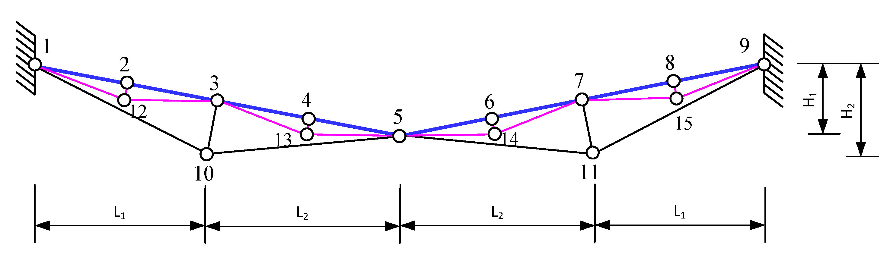
2.4. New Combined Two-Level Cable-Strut Suspension System

The weight of the discussed innovative two-level cable-strut steel system depends on the forces and the designed cross-sections of the upper hord. The lengths of the upper hord elements have a significant influence on this, particularly for medium and large-span structures. Therefore, in order to reduce the weight of the structure, especially for medium and large spans, it is suggested to use an innovative suspension system with a two-level cable strut (see Figure 6).
All elements of the upper hord in this structural system also have flexural stiffness ( E I 0 ) and are hinged together. The lower hord is composed of cable strut steel elements, similar to the previously investigated suspension structure (see Section 2.2), and we will refer to them as the first-level cable strut. The second-level cable strut in this new structural system divides the upper hord into eight elements. The heights of the first-level strut h 3,6 are chosen to stabilize the vertical displacements of the central hinge, similar to the single-level suspension structure (see Section 2.2), according to expression (17), i.e., h 3,6 0.5   f 0 1 + c o s φ . The heights of the second-level struts h 2,7 = h 4,8 = h 9,14 = h 11,15   should satisfy the following structural requirements: h 2,7 = h 4,8 0.5   h 3,6 and h 9,14 = h 11,15 0.5   h 10,13 . However, the heights of these struts should not be less than h i , j 0.35   h 2,4 .
The lengths of the rigid elements of the upper chord should be accepted within the following limits: l 1 2 = l 2 3 = l 3 4 = l 4 5 = l i = ( 4 ÷ 10 ) m . It is recommended to select the cross-sectional height of these rigid elements according to the following expression:
h c =   M m 2 16   H 2 c 4   + f y k 2   E c 2 M m   4   H c 2  
here: M m —bending moment in the middle of the rigid element of the upper chord; H —tensile force in this element; f y —steel strength; E —modulus of elasticity of steel; k = H / E I —element cross-section slenderness parameter; and c —cross section shape evaluation coefficient [37].
When the cross-section height h c is known, the required cross-sectional area can also be calculated:
A = H f y   1 + M m 2   h c   H c 2   .
It is necessary to mention that when determining h c and A , the required bending stiffness E I of the upper chord element should be predetermined from the limit displacement condition f m a x   f u by applying the expression (3) when x = l / 2 .

3. Comparative Study of Analytical Calculation and FEM Results

In order to verify the accuracy of the analytical solutions and assumptions made, numerical analysis was performed for all of the suspension structures studied. The structure length for all cases was chosen to be equal and set at L = 36.00 m. In this study, the behaviour of these structures was analysed under symmetrical loading. For all suspension structure variants, the permanent load of g = 4.20 kN/m and the variable load of s = 7.70 kN/m were assumed as characteristic values of the loads. Design load values were obtained by multiplying these values by the corresponding partial safety factors. The modulus of elasticity of steel was taken as E = 210 GPa. The cross-sectional dimensions of the elements are provided in the description of each structure. The numerical experiment was performed by computing the structures as geometrically nonlinear using the finite element method (FEM).

3.1. Suspension Structures with Two Straight Elements

The two-element suspension structures and applied loads are presented in Figure 7.
In the analysis of the two-element suspension structures, six different bending stiffness variants were applied with the following cross-sections: IPE360 (referred to as I1), RHS250 × 250 × 10 (R1), SHS400 × 200 × 6.3 (R2), SHS250 × 150 × 10 (R3), SHS300 × 100 × 10 (R4), and plate 180 × 40 (P1). It should be noted that in selecting these cross-sections their areas are nearly equal (area varies A = 72.00–72.70 cm2). This allows them to achieve equal elastic deformations of these elements under axial forces.
The most important results of the numerical experiment are presented in Table 1 and Figure 8.
In Table 1 and other tables, the abbreviation “Analytical” means that the results were obtained according to the methodology presented in Section 2 of this article and “FEM” means the results obtained by the authors when solving the structure as geometrically nonlinear by the FEM method.
As can be seen from the provided Table 1, the accuracy of the analytical solutions is quite good, as the maximum errors in calculating displacements do not exceed 4%. When calculating deflections, the errors are even smaller, not exceeding 2%, except in the case of cross-section “P1”, where the values of bending moments are relatively low.
When analysing the non-linear behaviour of this symmetrically loaded two-element suspension structure, it is important to note that the largest vertical displacements occur in the straight element of the upper chord with the smallest bending stiffness (P1). These displacements occur not only at the midpoint of the straight element (point “a”) but also at the central node (joint) of the structure, labelled “2”. This is clearly visible in the graph provided in Figure 8. It can be observed that in the case of a very small bending stiffness (P1), the structure of the straight elements deforms, approaching the shape of a quadratic parabola, and both the displacements at point “a” and node “2” become practically equal. As the values of the bending stiffness of the elements increase, the displacements at point “a” steadily decrease. The displacements at the central node “2” for the (I1) cross-section also become ten times smaller (see Table 1). However, it is important to note that such a decrease in displacements is accompanied by higher bending moments and, consequently, higher stresses due to the axial force and bending moment.
From Figure 8 and the data in Table 1, it can also be observed that in the case of the beam with the highest bending stiffness (I1), the displacements at the central node “2” are very small (only 38.1 mm). This means that the vertical displacement of this central node can be effectively controlled using the bending stiffness if required by the operating conditions.

3.2. Suspension Single-Level Cable-Strut Systems

The suspension single-level cable-strut system design scheme is presented in Figure 9. The upper chords, similar to the suspension structure (Section 3.1), were designed with the following six cross-sectional variants: IPE360 (I1), RHS250 × 250 × 10 (R1), SHS400 × 200 × 6.3 (R2), SHS250 × 150 × 10 (R3), SHS300 × 100 × 10 (R4), and plate 180 × 40 (P1). In all variants, the lower chord cross-section was taken as a round section of 32 mm diameter, and the vertical brace was chosen to have an RHS 60 × 60 × 4 cross-section. The cross-sectional dimensions of the lower chord elements were selected on the basis of both strength and stiffness requirements. The results of the numerical analysis are presented in Table 2 and Table 3, as well as Figure 10.
Analysing the data from Table 2, it can be seen that the displacements in the intermediate nodes (points a and b) and nodes 2 and 3 of this single-level cable-strut system are significantly smaller than those in the two-element suspension structure (Section 3.1). The displacements of the upper chord elements “1-2” and “2-3” for the I1 cross-section have been reduced by a factor of 5.9 times (from 0.29779 mm to 0.050248 mm). The same applies to the displacements of central node “3” that changed direction and was reduced twice (from 0.039296 mm to 0.019554 mm). It becomes evident that the bending stiffness EI of cross-section I1 is clearly too high for this system. When reducing this cross-section (and thus their bending stiffness EI values) from R1 to R4, the displacements at points “a” and “b” steadily increase, but they do not reach the maximum displacement values of the two-element suspension structure (see Table 1 and Table 2).
Even when using the flexible cross-section “P1”, the maximum vertical displacements of the upper chord of the single-level system are 2.06 times smaller than in the two-element suspension system. However, as seen from the displacement graph provided in Figure 11, the initial form of the structure is best stabilized by the cross-sections I1, R1, and R2. It should be noted that this graph is presented on a scale that is 10 times larger for clarity. The lower chord restricts the vertical displacements of nodes “2” and “4” and partially limits the displacements of the central node “3”.
When there is a higher upper chord stiffness, the displacements of point 2 and central hinge 3 become practically equal. In other words, the overall curve of the upper chord displacements is smooth, and the displacement of the central node “3” points downward. When less stiff cross-sections (R1–R4) are used, the vertical displacements of nodes “2” and “4” decrease slightly, as the central node steadily increases and changes direction when approaching cross-section R3, meaning that it rises upward. In the case of the flexible cross-section P1, the absolute value of the central node’s displacement approaches the displacement values of the upper chord points “a” and “b” (see Table 2 and Figure 10). Therefore, similar to the two-element suspension structure, to stabilize the displacements of this suspension system, it is necessary to select elements of the upper chord with a certain bending stiffness. It is important to note that the deflections of the upper chord elements in this suspension single-level cable-strut system are also significantly smaller than those in the two-element suspension system.
Comparing these two suspension structures systems (Figure 7 and Figure 9), it should be noted that the axial forces have decreased by approximately 1.5 times, and the bending moments for the stiffest cross-section (I1) have been reduced by up to 2.5 times (Table 3). Consequently, the stress values in the upper chord elements have become smaller by approximately 2.3 times. It should be noted that the resulting stresses in the upper chord elements increase steadily when the cross-sectional bending stiffness (from R1 to R3) is changed, as expected. However, in the case of cross-section R4, the resultant stresses, compared to cross-section R3, decrease by almost 7 percent. This means that, while satisfying the stiffness requirements, it is possible to choose upper chord cross-sections with lower bending stiffness but certain shapes in which the stresses will not be at their maximum. In some cases, if the stiffness requirements are met, a flexible element such as P1 may be suitable. Although in this case, the displacements are greater than those of the stiff elements R1–R4, the axial forces increase only slightly (up to 12%), but the resultant stresses decrease significantly, by up to 33%.
In summarizing the results obtained, it can be said that the suspension single-level cable-strut system, due to its innovative form, is more efficient than the two-element suspension structure in terms of both deflection and force criteria. It can be expected that it will also be more rational in terms of weight criteria.

3.3. Suspension Two-Level Cable-Strut System

The suspension two-level cable-strut system is presented in Figure 11. In this system, four different cross-sectional variants of the upper chord were analysed. The upper chord of the system in this case was designed using the following different cross-sections: IPE160 (I2), RHS80 × 140 × 5 (R5), IPE160 on the weak axis (I3z), and a plate 100 × 20 (P2). In all variants, the lower chord of the was taken to be the same as that of the ten-element system—a 32 mm diameter round section. The two-level lower chord has a smaller cross-section, a 25 mm diameter round section. The strut was designed using an RHS 60 × 60 × 4 cross-section. It should be noted that the areas of the upper chord cross-sections are nearly equal. Summarizing the obtained results, it could be emphasized that this suspension system, due to its innovative shape, is more efficient than the ten-element suspension structure (see Section 3.2), both in terms of displacements and in terms of stresses. It can be expected that it will also be more rational according to the weight criterion.
The results of the numerical analysis are presented in Table 4, Table 5 and Table 6, as well as Figure 12. Analysing the results of the calculation of this more complex system, it can be noticed that the displacements of the intermediate points of the upper chord (“a”, “b”, “c”, and “d”) and nodes of this two-level cable-strut system are smaller than those of the upper chord elements of the suspension single-level system.
In the single-level system, the upper chord cross-sections are larger compared to the two-level system, as well as compared to the two-element system. Just like in the single-level system with the largest bending stiffness of the upper chord cross-section (I2), the deflection curve also becomes smoother, and the displacement of central node “5” moves down (see Figure 12). As the bending stiffness of the upper chord elements decreases (from R5 to P2), the chord’s deflections increase, and with the I3 cross-section, the displacement of the central node’s “5” changes direction, i.e., it rises upward (see Table 4 and Figure 12). The highest displacement values occur with the flexible cross-section P2. If we compare the displacements of chord nodes “a”, “b”, “c” and “d”, the maximum values are reached at point “c” for cross-sections I2 and R5, and when applying the I3z and P2 cross-sections, the maximum displacement occurs at point “b”. It should be noted that when changing the cross-sections, the displacement at point “d” practically changes not much, mainly due to the displacements of the central node “5”. It can be observed that to stabilize the vertical displacements of this two-level cable-strut system (similar to the single-level cable-strut system in Section 3.2), it is necessary to select the required bending stiffness EI of the upper chord elements.
Talking about the forces of the two-level cable-strut system (Figure 11), it should be noted that, as expected, they are significantly smaller than in the single-level cable-strut system (Figure 9). The axial forces in these elements (Table 5) compared to the single-level cable-strut system have decreased approximately 1.45 times and the bending moments by approximately 4.9 times when the upper chord is of the highest stiffness. Regarding the influence of the cross-sectional bending stiffness EI on the axial forces in the upper chord of the two-level cable-strut system, it should be noted that they change very little (increase by an average of about 13%, when changing cross-sections from I2 to P2). Note that in all cases, the maximum axial force is at point “a” while the minimum is at point “d”. The difference between these forces is approximately 11–13%.
The values of bending moments in the two-level cable-strut system (Table 5) change significantly as these cross-sections vary: about 2 times for the R5 cross-section, about 5 times for the I3z cross-section, and about 50 times for the flexible P2 cross-section. The total stresses in these elements change unevenly as the cross-sections change from I2 to P2 (see Table 6). When changing the cross-sections from I2 to I3z, these stresses increase by about 19%, but with the flexible P2 cross-section, the total stresses (compared to the I2 cross-section) decrease about 1.5 times.
In summary, it can be said that the new two-level cable-strut system, with the same system length and under the same loads, is more effective than the single-level cable-strut system in terms of both deflection and forces criteria. It should be noted that the efficiency of this system increases as the length of the system increases.

4. Conclusions

This article discusses three steel suspension roof structural systems consisting of primary straight suspension elements with bending stiffness. After performing the arrangement, calculation, and behaviour analysis of these new steel structure suspension systems, the following conclusions can be drawn:
1. An analytical calculation method has been developed for a suspension structure of two straight elements with bending stiffness under symmetrical loads. Using the concept of fictitious displacement, analytical expressions are provided for the displacements and forces of such composed straight inclined elements, taking into account the displacement of the central hinge. A numerical experiment revealed that the accuracy of these solutions, which consider the refined slenderness parameter k 1 l for inclined elements, is good and the errors do not exceed 3% compare to FEM analysis.
2. It has been determined that the shape of such a straight beam suspension structure, from a rational production and operation perspective, unfortunately, is not balanced under uniformly distributed loads. A greater initial form stabilization effect can be achieved by applying an innovative cable-strut suspension steel system in which the straight upper chord suspension elements are additionally “supported” by a lower chord.
3. The compositional parameters were obtained for an innovative single-level cable-strut suspension system, consisting of straight elements and a lower supporting chord, which determined the required minimum height of its strut stabilizing the vertical displacements of the central hinge and, at the same time, the displacements of the entire system. It has been established that the required strut height directly depends on the initial sag f 0 of this suspension system.
4. An analysis of the innovative suspension steel structures system, consisting of straight elements and a supporting lower chord, has been presented. A formula has been obtained to determine the axial force of the strut. It was observed that the axial force in the strut is not constant and depends not only on the displacement of the node connecting the upper chord elements and the strut but also on the displacements of these chord elements.
5. To verify the accuracy of the analytical solutions and the adopted assumptions, a numerical analysis of the three suspension structural systems examined was carried out using the FEM. When analysing the non-linear behaviour of a symmetrically loaded two straight-element structure, it was determined that with very low bending stiffness, the two straight-element structure deforms, approaching the shape of a quadratic parabola. When the bending stiffness of the straight elements is increased, the displacements of the structure decrease, but their bending moments and stresses increase.
6. It has been determined that the displacements and element forces of the single-level cable-strut and two-level cable-strut suspension systems are significantly smaller than those of the two-element suspension structure. The displacements of these suspension systems were found to be constrained not only by the bending stiffness of the upper chord elements but also by the lower supporting chords. It was also established that the forces and displacements of the two-level cable-strut system are smaller than those of the single-level cable-strut system. In its elements, compared to the single-level cable-strut system, the axial forces decreased approximately 1.45 times and the bending moments approximately 4.9 times.
7. Summarizing the results obtained, it can be stated that the new two-level cable-strut suspension steel system, under the same initial conditions, is more efficient than two-element suspension steel structures and single-level cable-strut suspension steel systems. It should be applied not only to medium-sized but also to large-span roof structures.

Author Contributions

Conceptualization, A.J.; Methodology, A.D.; Software, A.D.; Validation, A.J., A.D. and L.U.; Formal analysis, A.J. and A.D.; Investigation, A.J. and A.D.; Resources, A.J., A.D. and L.U.; Data curation, A.J. and A.D.; Writing—original draft, A.J., A.D. and L.U.; Writing—review & editing, A.J. and A.D.; Visualization, A.J. and A.D.; Supervision, A.J. and A.D.; Project administration, A.J. and A.D.; Funding acquisition, A.J., A.D. and L.U. All authors have read and agreed to the published version of the manuscript.

Funding

This research received no external funding.

Data Availability Statement

Data are contained within the article.

Conflicts of Interest

The authors declare no conflicts of interest.

References

  1. Bucholdt, H.A. An Introduction to Cable Roof Structures, 2nd ed.; Thomas Telford: London, UK, 1999. [Google Scholar]
  2. Engel, H. Tragsysteme/Structure Systems; Hatje Cantz Verlag GmbH: Berlin, Germany, 2009. [Google Scholar]
  3. Krishna, P. Tension Roofs and Bridges. J. Constr. Steel Res. 2001, 57, 1123–1140. [Google Scholar] [CrossRef]
  4. Schlaich, J.; Bergermann, R.; Leich, W. Light Structures, 2nd ed.; Prestel: Munich, Germany, 2005. [Google Scholar]
  5. Schlaich, J. Conceptual design of light structures. J. Int. Assoc. Shell Spat. Struct. 2004, 45, 157–168. [Google Scholar]
  6. Krishna, P.; Agrawal, T.P. Cable-Suported Roof; McGaw-Hill: Kingsport, TN, USA; New York, NY, USA, 1978. [Google Scholar]
  7. Lewis, W. Tension Structures: Form and Behavior; Thomas Telford Ltd.: London, UK, 2003. [Google Scholar]
  8. Irvine, H.M. Cable Structures; Dover Publications: New York, NY, USA, 1992. [Google Scholar]
  9. González Quelle, I. Cable Roofs. Evolution, Classification and Future Trends. In Proceedings of the International Association for Shell and Spatial Structures (IASS) Symposium, Valencia, Spain, 28 September 2009. [Google Scholar]
  10. Otto, F. Gestalt Finden; Edition Axel Menges: Fellbach, Germany, 2001. (In German) [Google Scholar]
  11. Kulbach, V. Cable Structures. Design and Analysis; Estonian Academy Publisher: Tallinn, Estonia, 2007. [Google Scholar]
  12. Göppert, K.; Stein, M. A spoke wheel roof for the World’s largest convertible roof. The new Commerzbank Arena in Frankfurt, Germany. Struct. Eng. Int. 2007, 4, 282–287. [Google Scholar] [CrossRef]
  13. Berger, H. Light Structures-Structures of Light: The Art and Engineering of Tensile Architecture; Birkhauser: Basel, Switzerland, 2002. [Google Scholar]
  14. Pakrastinsh, L.; Rocens, K.; Serdjuks, D. Deformability of hierarchic cable roof. J. Constr. Steel Res. 2006, 62, 1295–1301. [Google Scholar] [CrossRef]
  15. Shimoda, M.; Yamane, K.; Shi, J.X. Non-parametric shape optimization method for designing cable net structures in form finding and stiffness maximization problems. Int. J. Solids Struct. 2018, 146, 167–179. [Google Scholar] [CrossRef]
  16. Schlaich, M.; Golenhofen, D. Hanging Glass Roof in Heilbronn, Germany. Struct. Eng. Int. 2018, 12, 179–181. [Google Scholar] [CrossRef]
  17. Zhang, N.; Luo, B.; Liu, H.; Zhang, M. Prestress Self-Equilibrium Force-Finding Method for Cable-Supported Grid Structures Considering Zero-Stress State Form-Finding and the Construction Process. Buildings 2022, 12, 749. [Google Scholar] [CrossRef]
  18. Jennings, A. Deflection theory analysis of different cable profiles for suspension bridges. Eng. Struct. 1987, 9, 84–94. [Google Scholar] [CrossRef]
  19. Cao, J.; Shao, X.; Zhan, J.; Zhang, J.; Wang, Y. A simplified analysis method for long-span suspension bridges within the deck overlay retrofitting process from asphalt to UHPC. Eng. Struct. 2023, 289, 116122. [Google Scholar] [CrossRef]
  20. Juozapaitis, A.; Norkus, A. Displacement analysis of asymmetrically loaded cable. J. Civ. Eng. Manag. 2004, 10, 277–284. [Google Scholar] [CrossRef]
  21. Ernst, H.J. Der E-Modul von Seilen unter Berücksichtigung des Durchhanges. Der Bauingenieu 1965, 40, 52–55. [Google Scholar]
  22. EN 1993-11. Design of Steel Structures, Part 1-11: Design of Structures with Tension Components. CEN: Brussels, Belgium, 2005.
  23. Rizzo, F.; D’Asdia, P.; Lazzari, M.; Procino, L. Wind action evaluation on tension roofs of hyperbolic paraboloid shape. Eng. Struct. 2011, 33, 445–461. [Google Scholar] [CrossRef]
  24. Xue, S.; Zhao, Z.; Li, X.; Liu, R.; Dezhkam, M.; Lu, Z.; Liu, T.; Fan, Q.; Jing, H. Shaking Table Test Research on the Influence of Center-Hung Scoreboard on Natural Vibration Characteristics and Seismic Response of Suspen-Dome Structures. Buildings 2022, 12, 1231. [Google Scholar] [CrossRef]
  25. Peil, U. Statik der Dachtragwerke von Stadien. Stahlbau 2005, 74, 159–177. [Google Scholar] [CrossRef]
  26. Rizzo, F.; Sadhu, A.; Abasi, A.; Pistol, A.; Flaga, Ł.; Venanzi, I.; Ubertini, F. Construction and dynamic identification of aeroelastic test models for flexible roofs. Arch. Civ. Mech. Eng. 2023, 23, 16. [Google Scholar] [CrossRef]
  27. Rizzo, F.; Sepe, V. Static loads to simulate dynamic effects of wind on hyperbolic paraboloid roofs with square plan. J. Wind Eng. Ind. Aerodyn. 2015, 137, 46–57. [Google Scholar] [CrossRef]
  28. Li, S.; Yao, G.; Wang, W.; Yu, X.; He, X.; Ran, C.; Long, H. Research on the Diffusion Model of Cable Corrosion Factors-Based on Optimized BP Neural Network Algorithm. Buildings 2023, 13, 1485. [Google Scholar] [CrossRef]
  29. Xu, J.; Chen, W. Behavior of wires in parallel wire stayed cable under general corrosion effects. J. Constr. Steel Res. 2013, 85, 40–47. [Google Scholar] [CrossRef]
  30. Ludescher, G.; Braun, F.; Bachmann, U. Stress-ribbon roof structures of the new Stuttgart trade fair exhibition halls. Struct. Eng. Int. 2007, 1, 22–27. [Google Scholar] [CrossRef]
  31. Zimmermann, M.; Deillon, A. A new roof for the Émile Cohl Art School in Lyon. Struct. Eng. Int. 2018, 28, 171–177. [Google Scholar] [CrossRef]
  32. Furtado, R.; Quinaz, C.; Bastos, R. New Braga Municipal Stadium, Braga. Struct. Eng. Int. 2005, 15, 72–76. [Google Scholar] [CrossRef]
  33. Ban, S.; Tsubota, H.; Motohashi, S.; Yoshida, A. Suspended roof for the Olympic Skating Arena, Nagano. Struct. Eng. Int. 2018, 8, 187–188. [Google Scholar] [CrossRef]
  34. Shimanovsky, A.V.; Shilinsky, V.V.; Shaban, N.A. Mechanics of Suspension System; Stal: Kiyv, Russia, 2010. (In Russian) [Google Scholar]
  35. Strasky, J. Stress-Ribbon and Supported Cable Pedestrian Bridges; Thomas Telford Ltd.: London, UK, 2005. [Google Scholar]
  36. Juozapaitis, A.; Sandovič, G.; Jakubovskis, R.; Gribniak, V. Effects of flexural stiffness on deformation behaviour of steel and FRP stress-ribbon bridges. Appl. Sci. 2021, 11, 2585. [Google Scholar] [CrossRef]
  37. Budziński, R. Numerical analysis of cable net structure with application of different pretensioning methods. Czasopismo Inżynierii Lądowej, Środowiska i Architektury/J. Civ. Eng. Environ. Archit. 2019, 66, 47–64. Available online: https://yadda.icm.edu.pl/baztech/element/bwmeta1.element.baztech-01dc5e98-f87d-458f-9d19-c4cab649044e (accessed on 10 January 2023.).
  38. Stauske, D. Drahtseile für Seilbauwerke. Stahlbau 2000, 69, 612–618. [Google Scholar] [CrossRef]
  39. EN 1993-1-8; Eurocode 3, Design of Steel Structures, Part 1-8: Design of Joints. CEN: Brussels, Belgium, 2005.
  40. Petersen, C. Stahlbau: Grundlagen der Berechnung und Baulichen Ausbildung von Stahlbauten (German Edition); Springer Vieweg: Wiesbaden, Germany, 2013. [Google Scholar]
  41. Bučmys, Ž.; Daniūnas, A.; Jaspart, J.-P.; Demonceau, J.-F. A component method for cold-formed steel beam-to-column bolted gusset plate joints. Thin-Walled Struct. 2018, 123, 520–527. [Google Scholar] [CrossRef]
  42. Juozapaitis, A.; Sharaskin, V.; Grigorjeva, T.; Valiunas, B. Analysis and arrangement of suspension structures from straight-line elements of finite flexural stiffness. In Theoretical Foundations of Civil Engineering; Szczesniak, W., Ed.; Warsaw University of Technology: Warsaw, Poland, 2002; Volume 2, pp. 887–896. [Google Scholar]
  43. Pałkowski, S. Statik der Seilkonstruktionen; Springer: Berlin/Heidelberg, Germany, 1990. (In German) [Google Scholar] [CrossRef]
  44. Pałkowski, S. Some problem of calculation and design of cable structures. In Proceedings of the 11th International Conference on Metal Structures ICMS-2006, Rzeszow, Poland, 21–23 June 2006. [Google Scholar]
  45. Ruchwa, M.; Matuszkiewicz, M. Zastosowanie Metody Elementow Skończonych w obliczeniach statycznych. Biuletyn WAT 2010, LIX, 363–377. [Google Scholar]
  46. Rezaiee-Pajand, M.; Mokhtari, M.; Masoodi, A.R. A novel cable element for nonlinear thermo-elastic analysis. Eng. Struct. 2018, 167, 431–444. [Google Scholar] [CrossRef]
  47. Qin, J.; Ju, Z.; Liu, F.; Zhang, Q. Cable Force Identification for Pre-Stressed Steel Structures Based on a Multi-Frequency Fitting Method. Buildings 2022, 12, 1689. [Google Scholar] [CrossRef]
  48. Šaraškinas, V.; Kvedaras, A.K. Course and results of testing a suspended composite structure. Statyba 2000, 6, 315–321. [Google Scholar] [CrossRef]
  49. Qin, K.; Zhao, F.; Luo, Y.; Fang, B.; Chen, S. Aeolian Vibration Dynamic Analysis of Large-Span, Relaxed Antenna Cable Net Based on Finite Particle Method. Buildings 2024, 14, 105. [Google Scholar] [CrossRef]
  50. Rizzo, F.; Kopp, G.A.; Giaccu, G.F. Investigation of wind-induced dynamics of a cable net roof with aeroelastic wind tunnel tests. Eng. Struct. 2021, 229, 111569. [Google Scholar] [CrossRef]
  51. Costa, R.S.; Lavall, A.C.C.; da Silva, R.G.L.; dos Santos, A.P.; Viana, H.F. Cable structures: An exact geometric analysis using catenary curve and considering the material nonlinearity and temperature effect. Eng. Struct. 2022, 253, 113738. [Google Scholar] [CrossRef]
  52. Wei, J.; Guan, M.; Cao, Q.; Wang, R. Spatial combined cable element for cable-supported bridges. Eng. Comput. 2019, 36, 204–225. [Google Scholar] [CrossRef]
  53. Vu, T.-V.; Lee, H.-E.; Bui, Q.-T. Nonlinear analysis of cable-supported structures with a spatial catenary cable element. Struct. Eng. Mech. 2012, 43, 583–605. [Google Scholar] [CrossRef]
  54. Gwon, S.-G.; Choi, D.-H. Three-dimensional parabolic cable element for static analysis of cable structures. J. Struct. Eng. 2015, 142, 06015004. [Google Scholar] [CrossRef]
  55. Ding, M.; Luo, B.; Ding, S.; Shen, Y.; Huang, L. Experimental Investigation and Numerical Simulation of a Levy Hinged-Beam Cable Dome. Buildings 2021, 11, 110. [Google Scholar] [CrossRef]
  56. Gimsing, N.J. Cable Suported Bridges—Concept and Design, 2nd ed.; John Wiley & Sons: Chichester, UK, 1997. [Google Scholar]
  57. Fürst, A.; Marti, P.; Ganz, H.R. Bending of stay cables. Struct. Eng. Int. 2018, 13, 42–46. [Google Scholar] [CrossRef]
  58. Yu, Y.; Wang, X.; Chen, Z. A simplified finite element model for structural cable bending mechanism. Int. J. Mech. Sci. 2016, 113, 196–210. [Google Scholar] [CrossRef]
  59. Zhou, B.; Hu, Y.; Zheng, X.; Zhu, H. Bending behavior of a frictional single-layered spiral strand subjected to multi-axial loads: Numerical and experimental investigation. Appl. Sci. 2022, 12, 4792. [Google Scholar] [CrossRef]
  60. Yu, Z.; Yu, Y.; Wang, X.; Wu, X.; Liu, H. Experimental research on bending performance of structural cable. Constr. Build. Mater. 2015, 96, 279–288. [Google Scholar] [CrossRef]
  61. Farkas, J.; Jármai, K. 5—Large-span suspended roof members. In Design and Optimization of Metal Structures; Harwood Publishing: Chichester, UK, 2008; pp. 47–56. [Google Scholar] [CrossRef]
  62. Kmet, S.; Tomko, M.; Bin, M. Experimental and theoretical behaviour analysis of steel suspension members subjected to tension and bending. Steel Compos. Struct. 2012, 13, 343–365. [Google Scholar] [CrossRef]
  63. Cui, W.; Caracoglia, L.; Zhao, L.; Ge, Y. Examination of occurrence probability of vortex-induced vibration of long-span bridge decks by Fokker–Planck–Kolmogorov equation. Struct. Saf. 2023, 105, 102369. [Google Scholar] [CrossRef]
  64. Zhang, C. The active rotary inertia driver system for flutter vibration control of bridges and various promising applications. Sci. China Technol. Sci. 2023, 66, 390–405. [Google Scholar] [CrossRef]
Figure 1. Suspension steel structures with two elements in the case of symmetrical loading: (a) scheme of structure; (b) design scheme of a single straight suspension element.
Buildings 14 00661 g001
Figure 2. Suspension single-level cable-strut structure. Forces acting on the central hinge of the suspension system.
Buildings 14 00661 g002
Figure 3. Design scheme for a symmetrically loaded innovative suspension structure.
Buildings 14 00661 g003
Figure 4. Design scheme for the upper hord under a symmetrical load.
Buildings 14 00661 g004
Figure 5. Design scheme for a symmetrically loaded lower chord.
Buildings 14 00661 g005
Figure 6. Two-level cable-strut suspension structural system.
Buildings 14 00661 g006
Figure 7. Suspension structures with two elements.
Buildings 14 00661 g007
Figure 8. Vertical displacements of the two-element suspension structures.
Buildings 14 00661 g008
Figure 9. Design scheme of a single-level cable-strut suspension system.
Buildings 14 00661 g009
Figure 10. Displacement of the upper chord in the suspension single-level cable-strut system.
Buildings 14 00661 g010
Figure 11. Design scheme of the suspension two-level cable-strut system.
Buildings 14 00661 g011
Figure 12. Displacements of the upper chord of the suspension two-level cable-strut system.
Buildings 14 00661 g012
Table 1. The numerical results of two-element suspension structures.
StiffnessAnalysis MethodDisplacement, Axial Force, Bending Moment, Stresses
u z , a (m) u z , a , r e l u z , 2 (m) u z , 2 , r e l H a (kN) M a (kNm) σ x , a (MPa)
I1Analytical0.30901L/116.5−0.039296L/916.1731.21371.28511.5
FEM0.29779L/120.9−0.038085L/945.3742.33364.67505.7
Difference (%)3.63 3.08 −1.521.78
R1Analytical0.40484L/88.9−0.11367L/316.7749.24263.25481.00
FEM0.39128L/92.0−0.11056L/325.6758.03259.00476.1
Difference (%)3.35 2.73 −1.171.61
R2Analytical0.46670L/77.1−0.18739L/192.1765.74184.63454.7
FEM0.45253L/79.6−0.18314L/196.6772.61181.94450.5
Difference (%)3.08 2.27 −0.901.46
R3Analytical0.52241L/68.9−0.28490L/126.4786.28102.14399.2
FEM0.50805L/70.9−0.28024L/128.5790.95100.83396.1
Difference (%)2.75 1.63 −0.591.28
R4Analytical0.55044L/65.4−0.36086L/99.8801.6949.107311.0
FEM0.53655L /67.1−0.35678L/100.9804.8348.524309.1
Difference (%)2.52 1.13 −0.391.19
P1Analytical0.56373L/63.9−0.44031L/81.8817.324.3835204.8
FEM0.55183L/65.2−0.44853L/80.3819.894.0334197.9
Difference (%)2.11 1.87 0.317.98
Table 2. Displacement values of the single-level suspension cable-strut system calculated by FEM.
Stiffness of the Upper ChordDisplacements
u z , a
(m)
u z , a , r e l u z , 2
(m)
u z , b
(m)
u z , b , r e l u z , 3
(m)
u z , 3 , r e l
I10.050248L/716.40.0440020.060207L/598.00.019554L/1841.1
R10.070657L/509.50.0431970.078601L/458.00.014889L/2417.9
R20.094352L/381.50.0416770.098494L/365.50.0061287L/5874.00
R30.13784L/261.20.0370540.13052L/275.8−0.020192L/1782.9
R40.18998L/189.50.0276860.16000L/225.0−0.072094L/499.3
P10.26759L/134.50.000660730.17576L/204.8−0.21255L/169.4
Table 3. Axial force, bending moment, and stress values of the single-level suspension cable-strut system calculated by FEM.
Stiffness of the Upper ChordAxial Force, Bending Moment, and Stresses
H a
(kN)
H b
(kN)
M a
(kNm)
M b
(kNm)
σ a
(MPa)
σ b
(MPa)
I1501.33473.11143.40144.33227.7224.8
R1503.27475.05130.27131.72256.3254.6
R2506.75478.55115.29117.18287.9287.6
R3516.35488.1888.26790.549322.5325.1
R4532.84504.7256.08758.150302.5307.0
P1569.49541.465.41825.6987192.0193.9
Table 4. Displacement values of the suspension two-level cable-strut system calculated by FEM.
Stiffness of the Upper ChordDisplacements
u z , a
(m)
u z , 2
(m)
u z , b
(m)
u z , 3
(m)
u z , c
(m)
u z , 4
(m)
u z , d
(m)
u z , 5
(m)
I20.0468070.0383520.0712730.0483260.0827740.0617850.0817410.044666
R50.0843720.0423020.106690.0415330.109940.0467250.0937390.0049378
I3z0.109310.0461490.129050.033640.123210.0296560.089988−0.039917
P20.123370.0489450.140780.0269860.127370.0154870.080134−0.076673
Table 5. Axial force and bending moment values of the two-level cable-strut system calculated by FEM.
Stiffness of the Upper ChordAxial Force, Bending Moment
H a
(kN)
H b
(kN)
H c
(kN)
H d
(kN)
M a
(kNm)
M b
(kNm)
M c
(kNm)
M d
(kNm)
I2349.07334.96321.02306.9128.43528.70629.13829.504
R5366.42352.33338.74324.6514.25814.63315.01415.429
I3z381.85367.78354.76340.695.48735.67765.86546.0822
P2393.05378.99366.45352.390.527090.547380.566870.59013
Table 6. Stresses in the upper chord of the two-level cable-strut system.
Stiffnessof the Upper Chord σ a
(MPa)
σ b
(MPa)
σ c
(MPa)
σ d
(MPa)
I2435.4430.9427.9424.3
R5444.1444.1444.5445.3
I3z519.2523.7528.4534.4
P2275.6271.6268.3264.7
Disclaimer/Publisher’s Note: The statements, opinions and data contained in all publications are solely those of the individual author(s) and contributor(s) and not of MDPI and/or the editor(s). MDPI and/or the editor(s) disclaim responsibility for any injury to people or property resulting from any ideas, methods, instructions or products referred to in the content.

