Article

The Effect of Steel Fiber Content on the Workability and Mechanical Properties of Slag-Based/Fly Ash-Based UHPC

1
College of Civil Engineering and Architecture, Hunan Institute of Science and Technology, Yueyang 414006, China
2
Department of Mechanical Engineering, The University of Western Australia, Perth, WA 6009, Australia
*
Author to whom correspondence should be addressed.
Buildings 2025, 15(13), 2350; https://doi.org/10.3390/buildings15132350
Submission received: 22 May 2025 / Revised: 24 June 2025 / Accepted: 3 July 2025 / Published: 4 July 2025
(This article belongs to the Special Issue Sustainable and Low-Carbon Building Materials and Structures)

Abstract

This study investigates the influence of steel fiber content (0~3% by volume) on the workability and mechanical properties of ultra-high-performance concrete (UHPC) incorporating slag or fly ash. Although UHPC exhibits excellent strength and durability, its brittleness and high cost hinder broader applications. Steel fibers are known to improve mechanical performance and toughness, but their interaction with mineral admixtures remains underexplored. Flowability, compressive strength, flexural behavior, impact resistance, and microstructure were evaluated. Results show that increasing fiber content significantly reduces workability, with fly ash-based mixes showing better flowability than slag-based ones. Mechanical properties improved with higher fiber volume, and an optimal content of 2% achieved the best balance between workability and strength. Impact testing and stress–strain analysis revealed that steel fibers enhance energy absorption and toughness under dynamic loading. SEM observations at 3 days indicated initial bonding between the fibers and matrix, with minor microcracks, suggesting further strength development over time. This work offers a fresh understanding of the combined influence of steel fibers and mineral admixtures in UHPC and supports their effective application in durable and cost-efficient high-performance concrete design.

1. Introduction

Ultra-high-performance concrete (UHPC) originated from a proposal by Larrard and Sedran in 1994 [1]. Exhibiting compressive strength over 120 MPa, high toughness, and exceptional durability, UHPC is considered a revolutionary cementitious material. Its rapid early strength development and accelerated strength gain make it particularly advantageous for reducing construction time and improving project efficiency [2,3,4,5,6]. By optimizing the particle size distribution of cementitious materials (e.g., cement, fly ash, silica fume) and fine aggregates, and by incorporating a very low water/binder ratio (approximately 0.2) along with steel fiber reinforcement, UHPC achieves a highly compact microstructure. According to the theory of maximum packing density, micron-scale binders fill the voids between millimeter-scale aggregates, while sub-micron silica fume further densifies the pore structure. This results in significant reductions in both component size and self-weight, along with remarkable enhancements in seismic resistance and resistance to seawater corrosion [7,8]. Compared to conventional concrete, UHPC exhibits more than three times the compressive strength (exceeding 150 MPa), up to 300 times greater toughness, and fracture behavior akin to that of metallic materials, demonstrating outstanding reliability under overload or seismic conditions [9,10,11].
As a key reinforcing component in UHPC, steel fibers significantly suppress brittleness through a crack-bridging mechanism, while also enhancing the mechanical properties and fracture toughness of the matrix [12,13,14,15]. Steel fibers were first incorporated into concrete in the early 1800s [16], with American researcher Porter being among the first to explore their reinforcement potential [17]. It was not until the 1960s that the mechanical performance of steel fiber-reinforced concrete began to be systematically studied [18]. Subsequent research—including Graham and Romualdi’s fiber spacing theory [19,20] and Swamy and Naaman’s composite reinforcement theory [21]—gradually elucidated the mechanisms by which steel fibers hinder crack propagation. Recent atomic-scale computational materials science studies have revealed the interaction mechanisms between metals and substances such as cement matrices and steel fibers [22,23]. Although this study does not include such computational analyses, these previous studies provide valuable theoretical insights that help explain the strength improvement and performance optimization observed in steel fiber-reinforced concrete.
In terms of mechanical properties, previous studies by Yoo et al. [24,25] demonstrated that the rheological performance of UHPC significantly deteriorates with increasing steel fiber content, while flexural strength, crack mouth opening displacement, peak deflection, and fracture energy generally exhibit a linear increase. However, their work did not include a detailed evaluation of flexural toughness indices. Zhang Yujie [26] and colleagues investigated the effects of steel fiber dosage on the fundamental mechanical properties of concrete and found that both compressive strength and splitting tensile strength increased proportionally with fiber content. Nie et al. [27] reported that within the fiber content range of 0% to 4%, every 0.5% increment in steel fiber led to average increases of 5.79% and 6.68% in the mean and standard compressive strength values, respectively. However, the toughness index, flexural strength, and energy absorption initially increased and then declined, with a critical fiber volume content of approximately 3.5%. The orientation of steel fibers notably influenced flexural strength—fibers aligned parallel to the loading direction enhanced flexural strength by up to 61% compared to transversely arranged fibers [28]. Furthermore, hybrid fiber reinforcement (e.g., combining steel and palm fibers) exhibited synergistic effects, improving both initial crack strength and toughness [29]. Liu Jian et al. [30] demonstrated that fiber alignment substantially enhances UHPC performance: oriented steel fibers improved flexural strength by 10~80%, toughness by 20~100%, and tensile strength by 30~90%, compared to randomly distributed fibers. The application of steel fibers in load-bearing elements, particularly in terms of punching shear, flexural, and tensile properties, has been widely studied [31,32,33,34]. Research has indicated that steel fiber-reinforced concrete exhibits significantly superior punching shear performance under concentrated loads compared to ordinary concrete [35].
Despite the extensive research on the strengthening effects of steel fibers in UHPC [5,6,16,36,37,38], several critical issues remain unresolved. These include determining the optimal fiber content thresholds for different binder systems, understanding the response under dynamic (impact) loading, and clarifying how microstructural evolution governs macroscopic mechanical behavior. Different cementitious materials exert varying influences on the microstructure, strength development, and durability of concrete. For example, the pozzolanic effects of slag and fly ash promote secondary hydration reactions, thereby enhancing the density and impermeability of the concrete matrix. A systematic analysis of the synergistic effects of these materials under varying fiber contents can provide more precise mix design strategies for practical engineering applications. Most existing studies treat slag and fly ash as inert fillers and fail to elucidate how their particle morphology and pozzolanic activity influence fiber–matrix interfacial properties. Additionally, current evaluations of UHPC toughness largely rely on static flexural testing, while energy dissipation mechanisms under impact loading remain inadequately studied.
Investigating the effects of different steel fiber contents on concrete performance provides valuable guidance for achieving a balanced material design in practical engineering applications. Insufficient fiber content may fail to deliver the desired reinforcement, while excessive content can adversely affect workability and constructability [39]. There are different approaches in the literature for expressing steel fiber content, with common methods including volume fraction, weight fraction, and binder weight percentage [40,41]. The volume fraction provides a direct representation of the spatial distribution of steel fibers, offering a more accurate reflection of their impact on the mechanical properties and durability of concrete. In contrast, while weight fraction is convenient for calculations, it fails to accurately capture the volumetric effect of fibers, especially when there are variations in the densities of concrete and steel fibers. Binder weight percentage is often used to maintain the stability of the cementitious matrix, but it may overlook the relative volume ratio of fibers to the matrix, potentially affecting the accuracy of the results. Therefore, this study adopts the volume fraction method to express steel fiber content, as it more precisely reflects the fibers’ influence on the concrete’s properties and avoids errors associated with density differences.
This study systematically investigates the effect of steel fiber content (0~3%) on the workability, compressive/flexural strength, and strength development rate of UHPC incorporating 25% slag or 25% fly ash. Comparative analysis reveals distinct differences in the strength development patterns between the two binder systems. To quantitatively evaluate the reinforcing and toughening effects of steel fibers, dynamic impact testing using a Split Hopkinson Pressure Bar (SHPB) and three-point flexural tests were conducted. Furthermore, the mechanisms by which fiber dosage influences the strength evolution of UHPC were explored. Advanced microstructural characterization techniques, incorporating scanning electron microscopy (SEM), were employed to examine fiber distribution and the interfacial microstructure between the steel fibers and the cementitious matrix.

2. Materials and Methods

2.1. Materials

The primary materials used in this study include Portland cement (PC), slag (BFS), fly ash (FA), silica fume (SF), natural quartz sand, steel fibers, polycarboxylate-based superplasticizer, and water. Portland cement P·I 42.5 (PC) provided by China National Building Materials Co., Ltd. in Beijing, China, conforming to Chinese National Standard GB175-2023 [42], with a specific surface area of 353 m2/kg. Its chemical and physical properties are listed in Table 1 and Table 2. The FA used is Class II, supplied by Hunan Huadian Changsha Electric Power Co., Ltd. in Changsha, China, with a specific surface area of 427 m2/kg. As a spherical, aluminosilicate material with pozzolanic, shape, and filling effects, FA can significantly improve concrete properties. The BFS used is S95-grade, provided by Xiangtan Iron & Steel Company in Xiangtan, China, with a specific surface area of 446 m2/kg and a density of 2900 kg/m3. SF provided by Hunan Ferroalloy Group Co., Ltd. in Xiangxiang, China, characterized by a specific surface area of 18,500 m2/kg and a particle size of 0.1~0.5 μm. The superplasticizer was provided by Sika Building Materials Co., Ltd. in Suzhou, China, a light-yellow polycarboxylate-based material with 21% solid content and over 30% water reduction. The sand used was natural river sand from the Xiangjiang River in Hunan, China, filtered to exclude particles exceeding 2.36 mm in size. Its apparent density measures 2550 kg/m3, bulk density 1570 kg/m3, mud content 1.0%, and fineness modulus 3.0, classified as Zone I gradation. The sand grading results are shown in Table 3. Straight steel fibers provided by Hunan Sunshine Steel Fiber Co., Ltd. in Zhuzhou, China, measuring 13 mm in length, 0.2 mm in diameter, and with a tensile strength of around 2800 MPa were used.

2.2. Mix Proportion Design

Based on previous experimental findings [43,44], the UHPC mix design in this study was selected with a fixed water/binder ratio of 0.18, a binder/sand ratio of 1:1.1, and a superplasticizer dosage of 2%. The designed UHPC was divided into two groups: The first group replaced 25% of the cement with BFS (BFS-based UHPC), while the second group replaced 25% of the cement with FA (FA-based UHPC). The mix proportions of the two groups are shown in Table 4, where the water/binder ratio represents the mass ratio of water to the total binder materials (PC + SF + BFS or FA). The superplasticizer dosage is expressed as the ratio of the superplasticizer to the binder materials, and the steel fiber content is given as the percentage of steel fiber by total concrete volume.

2.3. Sample Preparation and Curing

Sample preparation and curing were carried out in strict accordance with GB/T 17671-2021 [45]. First, the dry materials—including PC, SF, BFS (or FA), and sand—were placed into a mixer and dry-mixed for 3 min. Then, water and the superplasticizer were added, and the mixture was stirred at low speed for 6 min, followed by high-speed mixing for 8 min until a uniform mixture was obtained. After achieving the desired consistency, steel fibers were gradually sprinkled into the mixer while stirring continuously. After all fibers were added, mixing continued for an additional 6 min. Once flowability was tested, the mixture was cast into molds. To reduce air entrapment and enhance compaction, light vibration was applied during casting. Each mold was filled in layers, with each layer vibrated 60 times to ensure uniform compaction. The surface was then leveled with a trowel. Once the specimens were molded, they were carefully labeled and wrapped in plastic film. They underwent an initial 24-hour curing period in the mold in the standard curing room before being removed and placed in a controlled curing chamber for further hardening. Curing continued until the specified testing ages were reached, at which point, mechanical and microstructural tests were conducted.

2.4. Test Methods

2.4.1. Flowability Test

The flowability of fresh UHPC was evaluated in accordance with GB/T 2419-2005 [46]. The fresh mixture was placed into the flow table mold in two layers. The first layer was filled to two-thirds of the mold height and tamped 15 times with a tamping rod. The second layer was then added and tamped another 15 times. After tamping, the mold was carefully lifted vertically, and the mixture was spread by dropping the flow table 25 times. The final spread diameter of the mixture was measured to assess flowability.

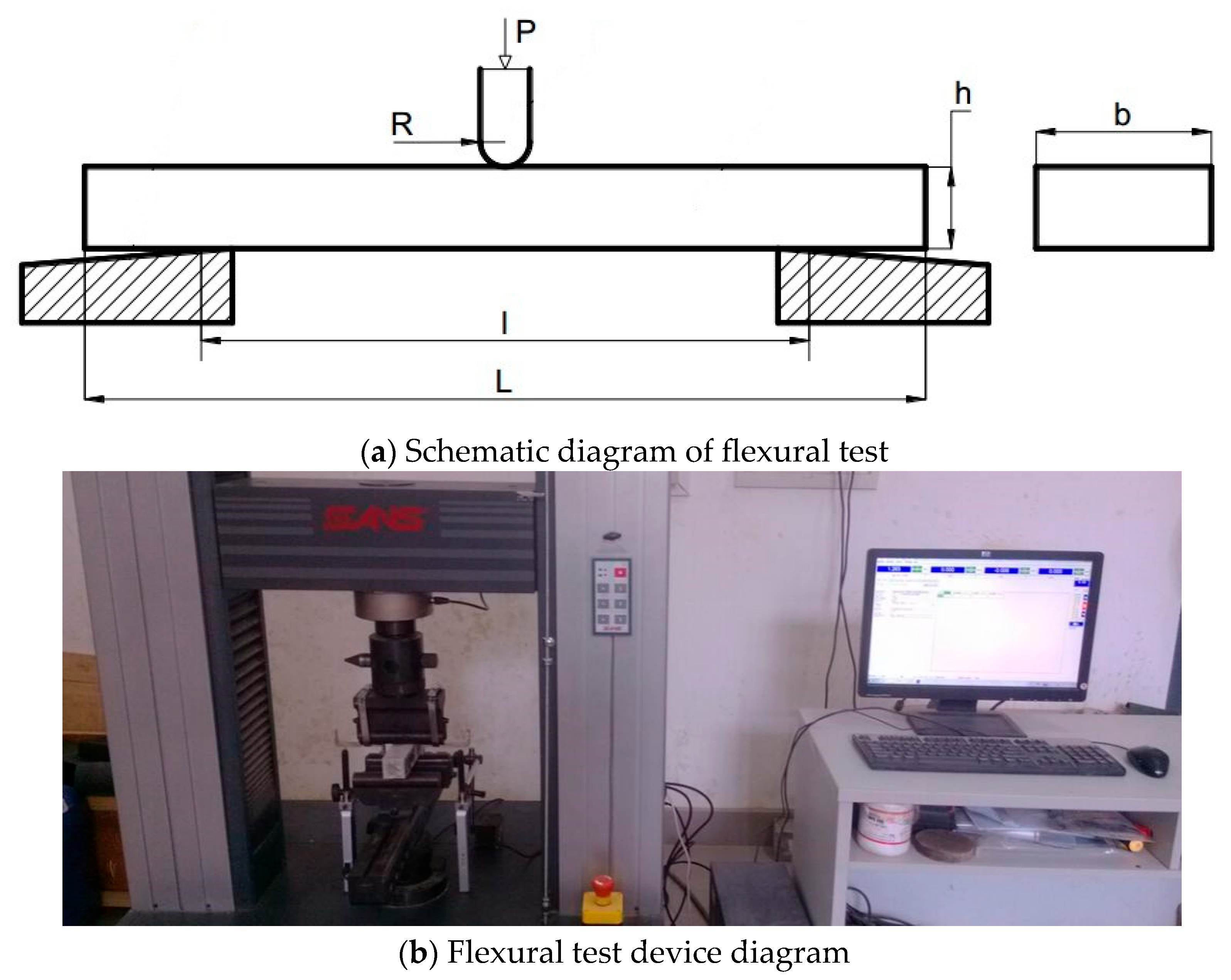
2.4.2. Compressive and Flexural Strength Tests

Strength evaluations under compression and flexure were performed as per the Chinese standard GB/T 17671-2021 [45]. Prismatic specimens measuring 40 × 40 × 160 mm were used for both tests. Three specimens were used for the flexural strength test, and six halves of those specimens were used for the compressive strength test. These six half-prisms were obtained by splitting each 40 × 40 × 160 mm prism at mid-span, resulting in specimens of approximately 40 × 40 × 80 mm. All compressive tests were conducted on these half-prisms to ensure consistency and comparability of the data. Figure 1 shows the strength test device diagram.
To ensure the accuracy and reproducibility of the results, the minimum number of specimens for each test was three, as required by GB/T 17671-2021. The reported strength values are the averages of these respective groups. The specimens were subjected to standard curing before testing, ensuring compatibility with practical engineering applications.

2.4.3. Flexural Toughness Test

Flexural toughness was evaluated through a static three-point flexural test using an MTS computer-controlled universal testing machine. The loading span was set at 100 mm, and specimens were placed on two support rollers. A line contact was ensured between the loading head and the specimen, oriented perpendicular to the specimen’s longitudinal axis.
A displacement-controlled loading mode was adopted, with a constant loading rate of 0.2 mm/min. During testing, both the load and deflection were continuously recorded. The load was measured by the machine’s internal force sensor, while deflection was captured by two linear variable differential transformers (LVDTs) placed symmetrically at the mid-span of the specimen. All data were collected and saved in real time via the computer data acquisition system. Each test group consisted of three specimens, all with dimensions of 40 × 40 × 160 mm. Figure 2 shows the experimental configuration.
Static toughness is typically evaluated by the area under the stress–strain curve. For the static toughness index ηk (where k = 5, 10, 20), it is defined as the relationship between the area under the curve and the unit volume at different strain levels.
The basic formula is:
η k = 0 ε k σ ( ε ) d ε
where:
  • ηk represents the toughness at a specific strain level (such as 5%, 10%, or 20%).
    σ(ε) is the stress at a given strain on the stress–strain curve.
    ε is the strain.
    εk is the corresponding strain level (e.g., 5%, 10%, or 20%).

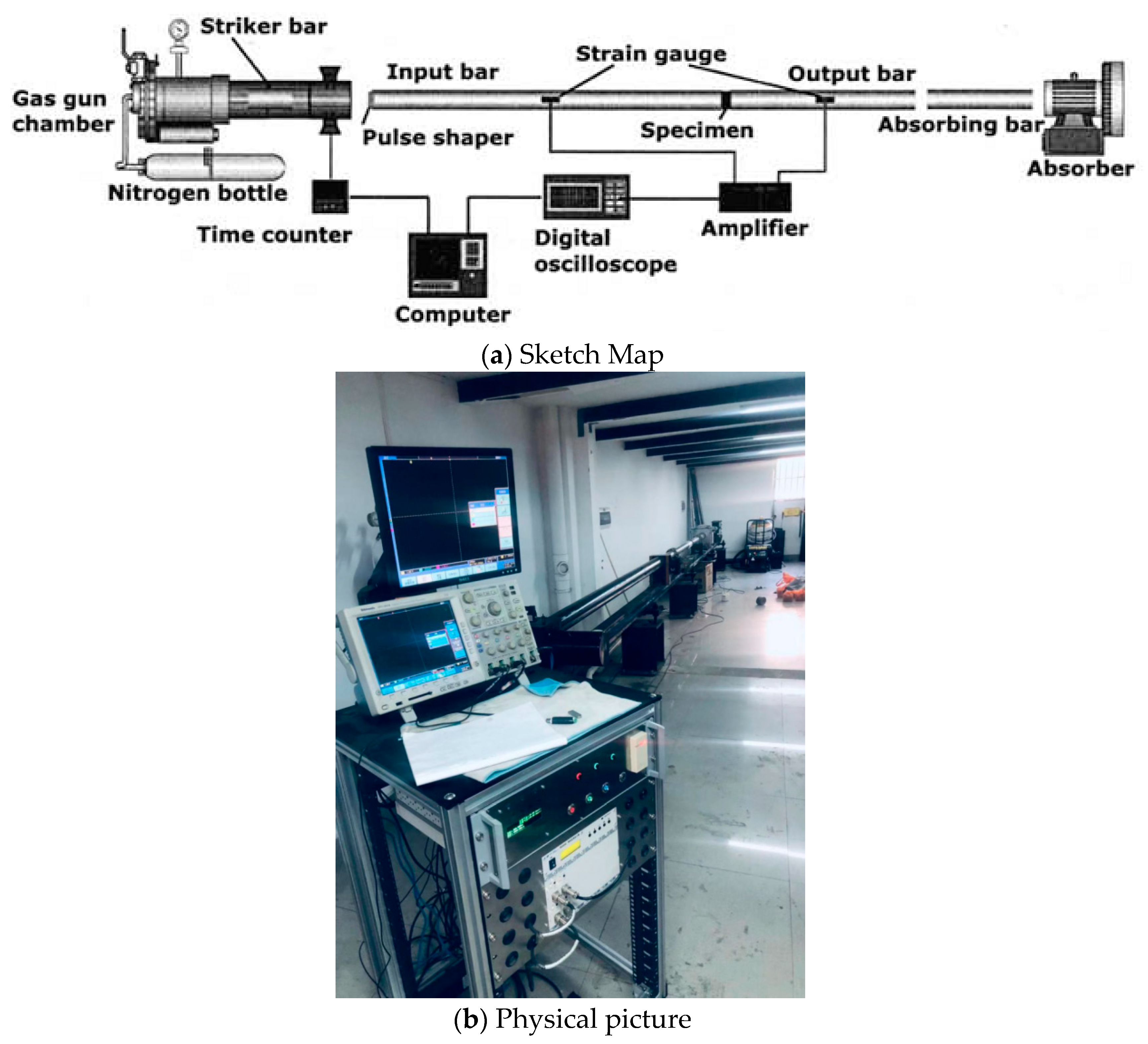
2.4.4. Split Hopkinson Pressure Bar (SHPB) Impact Compression Test

The SHPB testing system used in this study comprises a loading platform, air chamber with a launching device, incident bar, transmission bar, damping bar, confinement system, a high-speed dynamic strain data acquisition system, and specialized analysis software. The schematic and physical diagrams of the SHPB device are shown in Figure 3. The system employs a traditional SHPB apparatus, with the UHPC cylindrical specimen placed between two pressure bars. Specimens measuring 80 mm in diameter and 40 mm in height were employed. Every test group included 15 samples, divided into three sets subjected to different strain rates. Each strain rate condition was tested using five UHPC specimens.
The SHPB pressure bars consisted of high-grade alloy steel, measuring 80 mm in diameter. The incident and transmission bars were 6 m and 4 m in length, respectively, with strain gauges placed 3 m and 1 m from the specimen interfaces. The striker bar was 1.5 m long. The test principle involves accelerating the striker bar with high-pressure nitrogen to generate a one-dimensional stress wave in the incident bar. When encountering the specimen, the wave partially reflects and partially transmits into the transmission bar. The reflected wave travels back along the incident bar, while the transmitted wave propagates through the transmission bar. During impact, the specimen experiences a near-one-dimensional stress state. Dynamic strain gauges record the variation in strain over time in both incident and transmission bars. After data processing, the stress–strain response and corresponding strain rates of the specimen under impact compression can be obtained.

2.4.5. Scanning Electron Microscopy (SEM)

To observe the microstructural characteristics of UHPC, specimens were first crushed into small fragments. These fragments were then immersed in absolute ethanol for 24 h to halt further cement hydration. After immersion, samples were dehydrated in a vacuum oven until their weight remained stable. Once dried, the surfaces of the specimens were treated and prepared for imaging. SEM analysis was performed on the specimens using high-resolution SEM. The observation surface was selected to be perpendicular to the treated face of the specimen. Before imaging, the gold coating was applied using an ION SPUTTER E-1045 sputter coater to ensure conductivity and obtain high-quality micrographs. The SEM analyzed the UHPC matrix morphology, steel fiber distribution, and the fiber–matrix interfacial transition zone (ITZ).

3. Results and Discussion

3.1. Workability

Figure 4 illustrates the influence of varying steel fiber content on the flowability of UHPC incorporating 25% BFS or 25% FA. As shown, steel fiber incorporation markedly decreases UHPC workability in both cases, with a generally linear decreasing trend. The reduction becomes more pronounced as the fiber content increases.
For FA-based UHPC without steel fibers, the flow diameter reached 218 mm, indicating good workability. The fiber content rose from 1% to 3% and the flow diameter declined from 200 mm to 165 mm. For BFS-based UHPC, the flow diameter decreased from 180 mm to 150 mm across the same range of fiber content. Under identical fiber dosages, FA-based UHPC exhibited significantly greater flowability compared to BFS-based UHPC. This difference can be attributed to the spherical morphology and smooth surface of FA particles, which create a ball-bearing effect. This effect reduces interparticle friction and water demand, thereby improving flowability. These ultra-fine FA particles effectively fill gaps between cement particles, enhancing the packing density of the particles, reducing water trapped in agglomerates, and increasing the free water content in the paste—all of which improve flowability [44].
In contrast, the reduction in flowability in BFS-based UHPC is primarily due to the very high specific surface area of BFS. Although the surface of BFS particles is relatively smooth and contributes to void filling between cement grains, it also slows down the hydration reaction and alters the pore structure and distribution of the cementitious matrix, leading to a denser system but poorer initial workability [43].

3.2. Compressive Strength

Figure 5 shows how steel fiber dosage affects UHPC compressive strength with 25% BFS and 25% FA. For BFS-based UHPC without steel fibers (Figure 5a), rapid early-age strength development is observed, followed by a significant slowdown in strength gain at later ages. The incorporation of steel fibers substantially improves compressive strength, with the greatest increase observed at a fiber volume content of 1%.
Specifically, the 3-day compressive strength of the BFS-based UHPC without fibers is 80.0 MPa, increasing to 96.0 MPa, 99.0 MPa, and 104.7 MPa at 7, 28, and 56 days, respectively—representing increases of 20.0%, 23.8%, and 30.9% over the 3-day value. At 1% fiber content, the 3-day strength increases to 85.0 MPa, with corresponding 7-, 28-, and 56-day strengths of 113.0 MPa, 119.0 MPa, and 129.9 MPa—growth rates of 32.9%, 40.0%, and 52.8%. At 2% fiber content, the 3-day strength reaches 97.3 MPa, while the 7-, 28-, and 56-day strengths rise to 118.6 MPa, 128.0 MPa, and 136.0 MPa—showing more moderate increases of 21.9%, 31.6%, and 39.8%. With 3% fiber content, the 3-day compressive strength peaks at 106.9 MPa, followed by 128.0 MPa, 146.0 MPa, and 158.2 MPa at later ages—corresponding to increases of 19.7%, 36.6%, and 48.0%. Considering both flowability and compressive strength performance, a steel fiber volume content of 2% is identified as the optimal dosage for BFS-based UHPC.
The compressive strength of FA-based UHPC (Figure 5b) exhibits a significant increasing trend with a higher steel fiber content. Without fibers, the 3-day compressive strength reaches 42.0 MPa, increasing to 89.0 MPa, 100.0 MPa, and 120.0 MPa at 7, 28, and 56 days, respectively—growth rates of 111.9%, 138.1%, and 185.7%. At 1% fiber content, the 3-day strength is 50.0 MPa, with later strengths of 99.9 MPa, 120.0 MPa, and 134.2 MPa, corresponding to increases of 99.8%, 140.0%, and 168.4%. With 2% fiber, the 3-day strength rises to 65.0 MPa and progresses to 114.0 MPa, 136.0 MPa, and 147.6 MPa—growth rates of 75.4%, 109.2%, and 127.1%. At 3% fiber content, the 3-day strength reaches 80.0 MPa, increasing to 120.5 MPa, 150.0 MPa, and 170.7 MPa at later ages—representing respective increases of 50.6%, 87.5%, and 113.4%.
The incorporation of steel fibers into concrete significantly enhances its compressive strength through several mechanisms. Firstly, steel fibers strengthen the bond between the fibers and the matrix, promoting a close interaction between the steel fibers and the cementitious matrix [47]. Secondly, steel fibers effectively mitigate crack propagation through the crack-bridging effect, allowing them to withstand additional stress during the early stages of crack formation, thereby improving the compressive strength of the concrete [48]. Additionally, the inclusion of steel fibers improves the microstructure of the concrete by reducing the formation of capillary pores, which enhances its density and toughness [49].
Therefore, in both BFS- and FA-based UHPC systems, steel fibers markedly improve compressive strength. Strength development in both systems follows a rapid-then-gradual pattern—rapid at early ages and slower later. When fiber content is below 2.0%, the distributed fibers constrain lateral expansion during compressive loading, with this effect intensifying as the fiber content increases. Nonetheless, when the fiber content surpasses about 2%, excessive fiber volume may introduce internal defects, diminishing the toughening effect and slowing compressive strength gains [50]. The pozzolanic reaction promotes secondary hydration within the cement matrix, generating additional C-S-H gel, which significantly improves the microstructure of the concrete. These reactions enhance the density of the concrete by filling capillary pores, thereby increasing its compressive strength [51]. BFS-based UHPC exhibits greater early-age strength than FA-based UHPC, primarily due to FA’s delayed hydration. Its pozzolanic reaction occurs later, contributing to the gradual strength development [52].

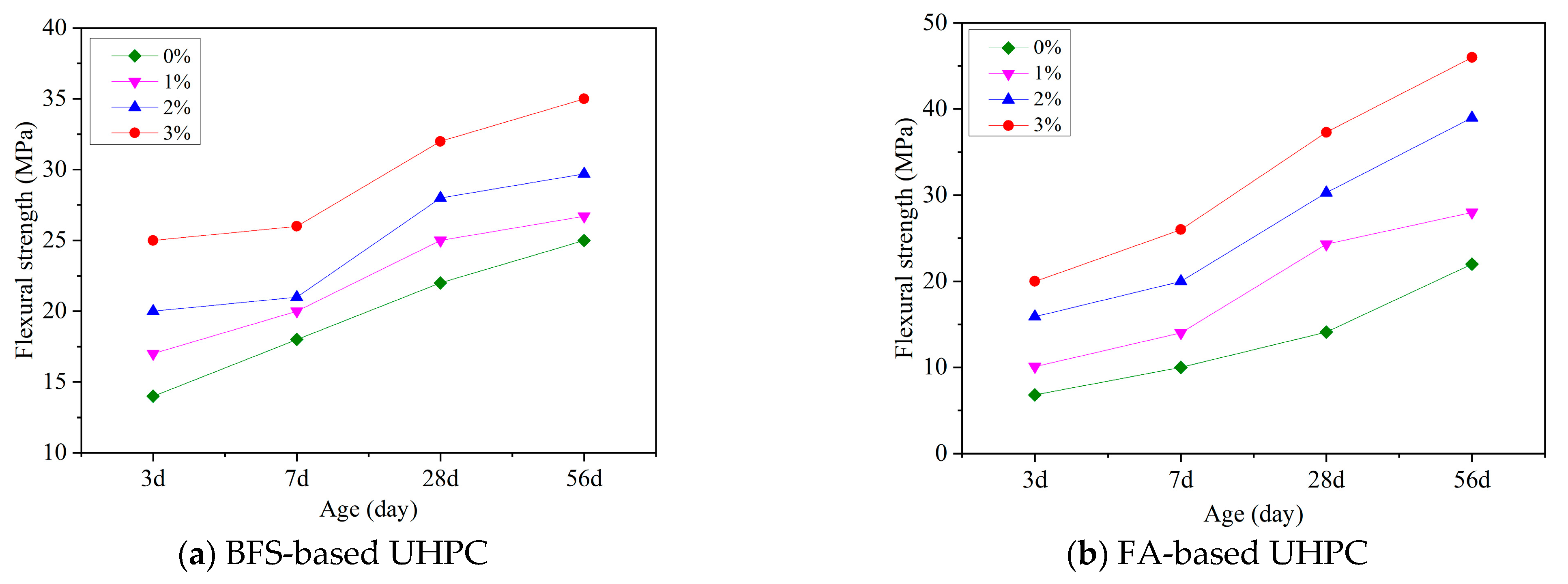
3.3. Flexural Strength

Figure 6 shows the flexural strength of BFS- and FA-based UHPC. For BFS-based UHPC (Figure 6a), the 3-day flexural strength without fibers is 14.0 MPa, increasing to 18.0 MPa, 22.0 MPa, and 25.0 MPa at 7, 28, and 56 days—gains of 28.6%, 57.1%, and 78.6%. With 1% fibers, the 3-day strength increases to 17.0 MPa, with later values of 20.0 MPa, 25.0 MPa, and 26.7 MPa—growth rates of 17.7%, 47.1%, and 57.1%. At 2% fiber content, the strength rises from 20.0 MPa to 21.0 MPa, 28.0 MPa, and 29.7 MPa—gains of 5.0%, 40.0%, and 48.5%. At 3%, the values are 25.0 MPa, 26.0 MPa, 32.0 MPa, and 35.0 MPa—corresponding to gains of 4.0%, 28.0%, and 40.0%. Thus, the flexural strength development of BFS-based UHPC mirrors its compressive strength: rapid at early stages, slowing over time [50]. Flexural performance is notably enhanced with the inclusion of steel fibers, with increases correlating to fiber content [53].
For FA-based UHPC (Figure 6b), flexural strength shows a clear upward trend. Without fibers, the 3-day flexural strength is 6.8 MPa, increasing to 10.0 MPa, 14.1 MPa, and 22.0 MPa at 7, 28, and 56 days—gains of 47.1%, 107.4%, and 223.5%. At 1% fiber content, the 3-day value is 10.1 MPa, with later values of 14.0 MPa, 24.3 MPa, and 28.0 MPa—corresponding to increases of 38.6%, 140.6%, and 177.2%. At 2%, values increase from 15.9 MPa to 20.0 MPa, 30.3 MPa, and 39.0 MPa—gains of 25.8%, 90.6%, and 145.3%. At 3% fiber content, the 3-day strength is 20.0 MPa, with later strengths of 26.0 MPa, 37.3 MPa, and 46.0 MPa—representing growth of 30.0%, 86.5%, and 130.0%. Compared to BFS-based UHPC, FA-based UHPC shows lower early flexural strength, but a higher growth rate later, due to the delayed pozzolanic reaction of FA [52].

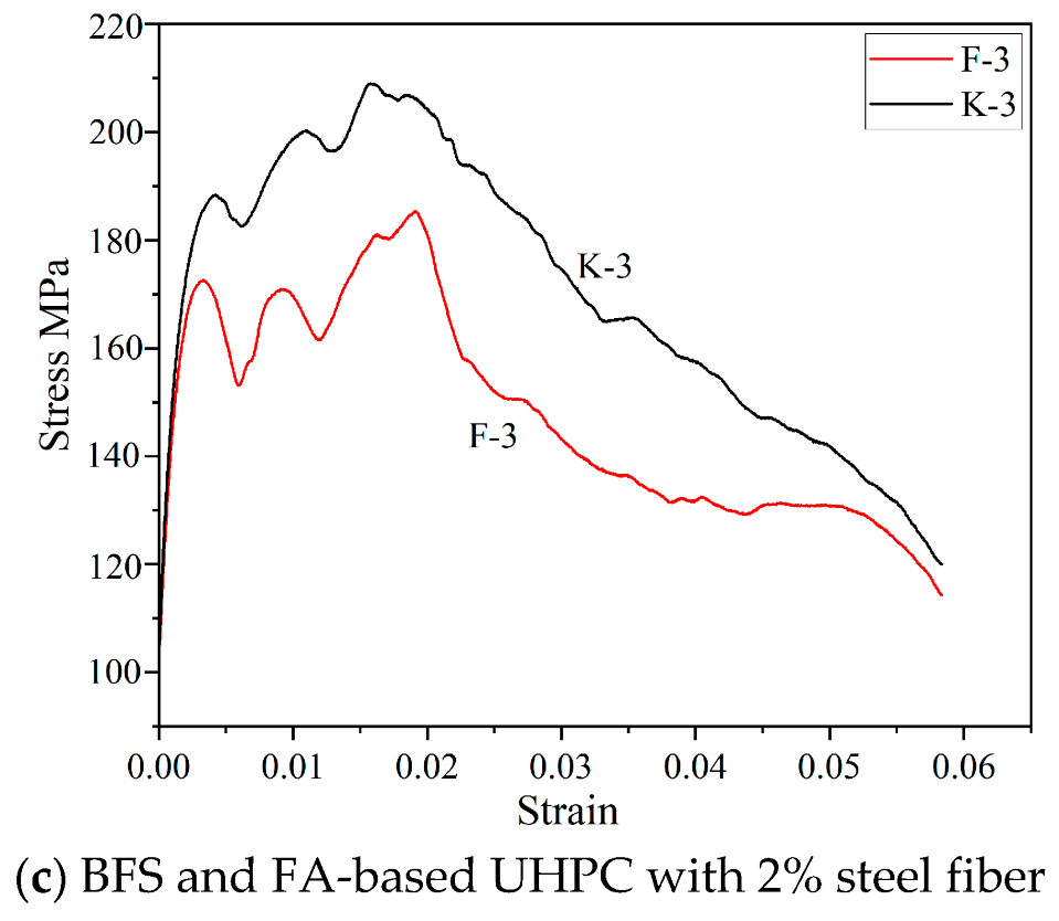
3.4. Flexural Behavior

Figure 7 shows the three-point flexural load-deflection curves of UHPC at 28 days. In the absence of steel fibers, UHPC exhibited brittle failure characterized by a sharp load drop immediately after initial cracking. The specimens fractured abruptly with a clean break and a distinct snapping sound, indicating a lack of energy absorption and post-cracking resistance.
Once steel fibers were added, the UHPC specimens showed significantly improved ductility. After initial cracking, they were still able to carry additional load due to the fiber-bridging effect. Before cracking, fiber content had little impact on the load-deflection curve, as the steel fibers and UHPC matrix deformed together under load with minimal differential strain. However, after cracking, the bond between the fibers and matrix became the dominant load-carrying mechanism, and differences in fiber content significantly affected the post-cracking behavior.
The descending portions of the load-deflection curves often exhibited fluctuations, representing the repeated pullout and re-engagement of fibers during fracture propagation. This behavior is consistent with observations by Yazıcı et al. [54], who linked it to fiber length, distribution, and bond strength with the matrix. Yardımcı et al. [55] also demonstrated that UHPC retains considerable load-bearing capacity after peak load due to steel fiber reinforcement, in contrast to the rapid collapse typical of conventional concrete.
Flexural toughness was evaluated according to ASTM C1018 [56], which defines the toughness index as the ratio of the area under the load-deflection curve up to a specified deflection to that up to the first crack. As shown in Table 5, the initial crack strength and deflection were relatively unaffected by the steel fiber content. However, the peak strength and deflection increased substantially with a higher fiber content.
Without fibers (K-1), a peak strength of 19.0 MPa and deflection of 0.30 mm were observed after 28 days. With increasing steel fiber content, both parameters rose steadily, demonstrating the fibers’ capacity to enhance post-cracking performance. This trend aligns with findings from Yoo et al. [24,25], who noted that while the initial crack is governed mainly by matrix strength, peak behavior and energy absorption are strongly influenced by fiber dosage.
The total energy absorbed by the specimen during fracture is indicated by the area beneath the load-deflection curve. The toughness indices η5, η10, and η20 reflect the material’s ability to dissipate energy after cracking. Higher values of these indices indicate better ductility and post-crack toughness. As seen in Table 5, all toughness indices increased significantly with higher steel fiber content, confirming the effectiveness of fiber reinforcement in improving UHPC’s flexural toughness.

3.5. Impact Compression Performance

Figure 8 shows how steel fibers influence UHPC’s fracture behavior during impact compression. As illustrated, UHPC samples lacking steel fibers exhibit explosive and fragmented failure under dynamic impact loading. At higher strain rates, the degree of fragmentation becomes more severe compared to lower strain rates, with the broken specimens producing more and smaller debris. Steel fiber addition alters the failure pattern from strictly brittle to enhanced ductility. When the steel fiber content reaches 3%, the specimen (F4) exhibits the least damage, producing the fewest and largest fragments after failure.
The influence of steel fibers on impact compression performance is notably less pronounced than their effect on flexural toughness. That is because, within the UHPC matrix, steel fibers primarily inhibit the formation of internal microcracks and impede the propagation of macrocracks. On one hand, the enhanced impact resistance of fiber-reinforced UHPC arises from the crack-bridging action of the steel fibers. On the other hand, from the perspective of stress wave propagation, tensile failure may also occur in UHPC. During impact testing, the sides of the specimen act as free surfaces, where reflected waves become tensile waves. Although these waves have a relatively low amplitude, the inherently low tensile strength of the matrix makes it susceptible to premature failure. Consequently, under identical strain rates, fiber-reinforced UHPC shows significantly less damage than plain UHPC, primarily because the randomly distributed fibers within the matrix form an interconnected network that effectively prevents tensile fracture [57,58]. Additionally, under impact loading, steel fibers help transfer and sustain loads and are not easily debonded or pulled out [59].
At a constant impact velocity, Figure 9 shows the UHPC’s dynamic stress–strain behavior. As shown, the UHPC specimen without fibers exhibits the lowest dynamic compressive strength, and the area under its stress–strain curve is the smallest—indicating the weakest energy absorption capacity and thus the poorest impact performance. The area under the stress–strain curve is an important indicator of impact resistance; the larger the area, the greater the energy absorption and the better the impact toughness.
Incorporating steel fibers notably enhances the UHPC’s impact resistance. When the fiber volume content is 1%, the dynamic compressive strength remains relatively low. As the fiber content increases, both the dynamic compressive strength and impact resistance improve. Furthermore, compared to the static compressive strength, the dynamic compressive strength of UHPC with 1% fiber is noticeably higher, following a trend similar to that observed under static loading (see Table 6). This effect occurs due to static loading conditions; steel fibers provide both crack-arresting and bridging effects [30], significantly enhancing compressive strength. Under dynamic loading, due to the short load duration, the fibers primarily exert a crack-arresting effect, while the bridging effect is diminished. As the fiber content increases further, the enhancement effect reaches a peak and then begins to decline, leading to a slight reduction in dynamic compressive strength. This trend aligns with that observed in static compressive strength tests [60].
For ductile materials, the energy stored corresponds to the area beneath the impact stress–strain curve during deformation and failure, which corresponds to the work done by the external force. Therefore, this area can be used as a quantitative measure of impact toughness. In this study, the impact velocity was consistently set at 13.61 m/s. Figure 9c illustrates the effect of 2% steel fiber inclusion: BFS-based UHPC exhibits better impact compressive strength than FA-based UHPC. In addition, as the fiber content rises, UHPC’s impact compressive strength steadily enhances.
In the early stage of loading, the material remains in the elastic deformation phase, where internal damage is minimal and strain-rate hardening dominates. During this phase, the rising segment of the stress–strain curve is approximately linear and shows little variation. As impact loading progresses, numerous internal microcracks begin to form and propagate. During this process, steel fibers effectively suppress rapid crack growth, improve the material’s ability to absorb energy, delay final failure, and significantly improve the impact toughness of UHPC [61].

3.6. SEM

Figure 10 presents an internal structural image of a UHPC specimen (F4) containing 3% steel fiber and FA, obtained after sectioning. The image was captured from the midsection of the specimen using a high-magnification microscopic imaging system after pre-wetting the surface with water. Exposure settings were adjusted to enhance contrast. The bright regions in the image indicate the locations of steel fibers, which appear to be relatively uniformly distributed throughout the matrix. The fibers are oriented in multiple directions, including longitudinal, transverse, and diagonal alignments.
In this study, steel fibers were added using a controlled process: after the UHPC slurry achieved the desired flowability, the fibers were gradually introduced through a sieve while stirring continuously. This method, suitable for laboratory conditions, effectively minimizes fiber agglomeration and ensures a uniform distribution, thereby improving the material’s overall mechanical performance. However, challenges remain in applying this method to practical engineering, especially in large-volume UHPC structures. In such cases, the addition of large quantities of steel fibers often leads to clustering, which not only reduces strength but may also compromise long-term durability. Therefore, achieving uniform fiber dispersion in large-scale applications requires further investigation and optimization.
Figure 11 displays scanning electron microscope (SEM) images of UHPC (F4) at 3 days. In Figure 11a, small gaps can be observed at the interface between some steel fibers and the cementitious matrix, indicating that the interfacial transition zone is not yet fully densified and the bonding remains relatively weak. This gradual densification of the interfacial microstructure is an important factor contributing to the continued strength development of UHPC at later ages. Conversely, Figure 11b shows that certain steel fibers have already formed a relatively tight bond with the matrix. This suggests that even at this early curing stage, a good level of interfacial adhesion has begun to develop. The excellent physical and mechanical properties of steel fibers, combined with their interfacial bonding capacity with the UHPC matrix, enable them to play a significant role in reinforcing and toughening the material.

4. Conclusions

This study examined how steel fiber content affects the workability and mechanical properties of UHPC containing BFS or FA. Key findings include:
(1)
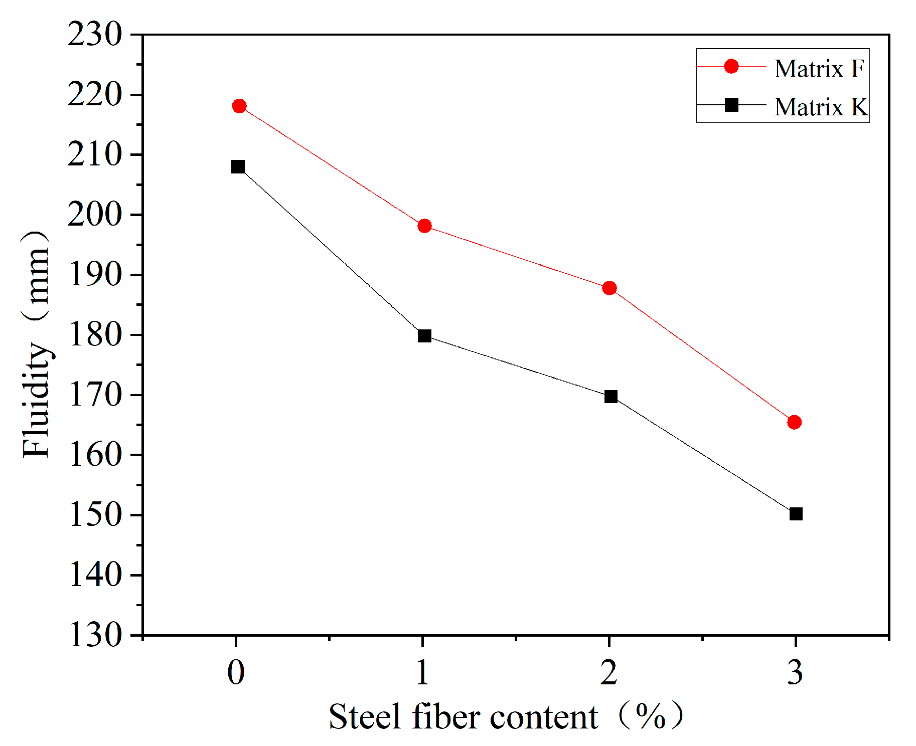
The flowability of UHPC decreases linearly with increasing steel fiber content. UHPC containing 25% FA exhibits higher flowability than that containing 25% BFS. This indicates that FA-based mixtures are more suitable for applications requiring high workability, such as densely reinforced structural elements or complex formworks.
(2)
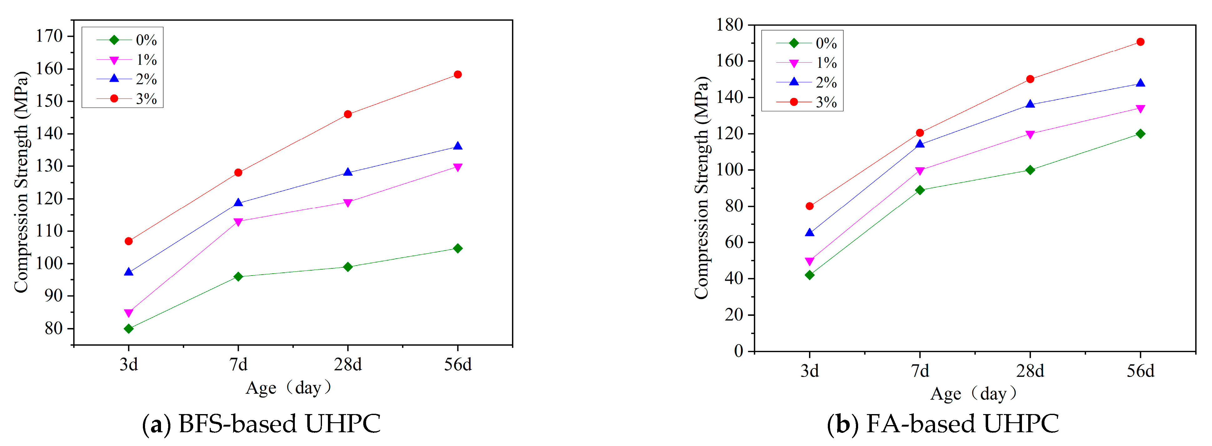
BFS-based UHPC develops higher early-age compressive strength—ideal for fast-track construction where rapid formwork removal and early load bearing are critical. In contrast, FA-based UHPC exhibits more pronounced strength gains at later ages due to the delayed pozzolanic reaction of fly ash, which contributes to matrix densification after the initial hydration period. Consequently, BFS-based UHPC is recommended for accelerated projects, whereas FA-based UHPC is better suited to applications that prioritize long-term durability.
(3)
Adding steel fibers greatly improves UHPC’s mechanical properties. As the fiber content increases, improvements are observed in compressive strength, flexural strength, flexural behavior, and impact toughness. A fiber volume content of 2% provides a good balance between mechanical performance and workability.
(4)
The area under the impact compressive stress–strain curve can be used as a quantitative indicator of impact toughness. The addition of steel fibers increases both the peak stress and the total energy absorbed, resulting in improved toughness and energy dissipation capacity. Notably, incorporating 2% steel fibers provides a significant enhancement in energy dissipation, which is particularly beneficial for structural components subjected to impact or dynamic loads, such as bridge expansion joints and seismic isolation bearings.
(5)
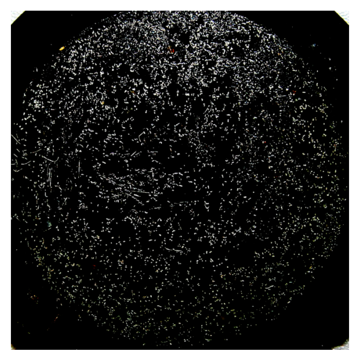
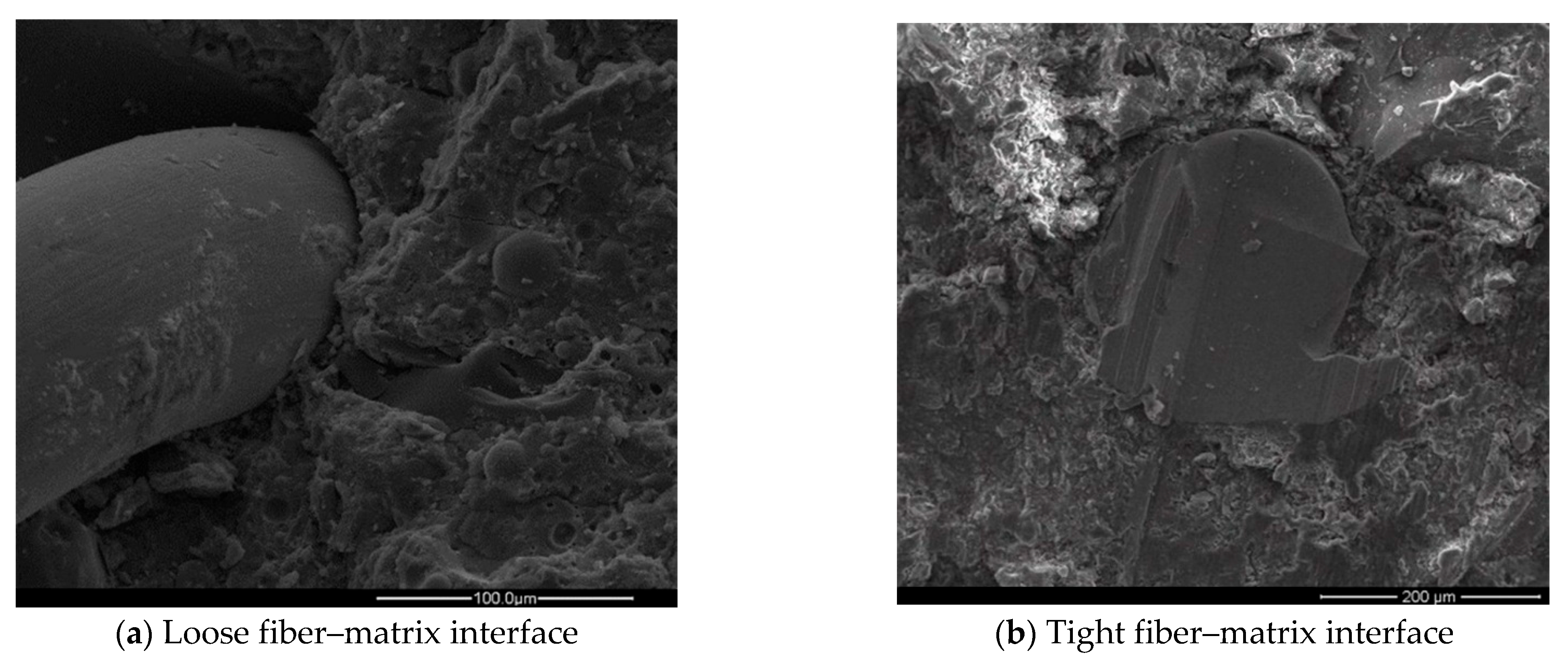
SEM analysis revealed that after 3 days of curing, small gaps still existed at the fiber–matrix interface. However, in some regions, a good bond had already formed, indicating that steel fibers begin to establish effective connections with the matrix at an early age. As curing progresses, the interfacial zone becomes denser, thereby supporting the continued development of strength.

Author Contributions

Conceptualization, L.W.; Methodology, L.W.; Software, R.W.; Validation, G.L.; Formal analysis, G.L. and R.W.; Investigation, R.W., M.H. and X.H.; Resources, L.W.; Data curation, R.W., M.H. and X.H.; Writing—original draft, G.L.; Writing—review & editing, L.W.; Visualization, R.W.; Supervision, L.W.; Project administration, L.W.; Funding acquisition, G.L. All authors have read and agreed to the published version of the manuscript.

Funding

Financial support from the Hunan Provincial Natural Science Foundation of China (No.2022JJ40161) and the Innovation Training Program for College Students (No.S202412658015) (No. S202510543071) are gratefully acknowledged.

Data Availability Statement

The original contributions presented in this study are included in the article. Further inquiries can be directed to the corresponding author.

Conflicts of Interest

The authors declare no conflict of interest.

References

  1. Richard, P.; Cheyrezy, M. Composition of reactive powder concretes. Cem. Concr. Res. 1995, 25, 1501–1511. [Google Scholar] [CrossRef]
  2. Xu, T.; Zhang, Z.; Bian, X.; Liu, Z. Influence of Steel Fibers on Creep Damage and Failure Behaviors of UHPC. J. Tongji Univ. (Nat. Sci.) 2023, 51, 1813–1821. [Google Scholar]
  3. Liu, F.; Lü, L.; Tan, Y. Study on mix proportion of white ultra-high performance concrete based on response surface method. Concrete 2023, 181–187. [Google Scholar] [CrossRef]
  4. Du, J.; Meng, W.; Khayat, K.H.; Bao, Y.; Guo, P.; Lyu, Z.; Abu-Obeidah, A.; Nassif, H.; Wang, H. New development of ultra-high-performance concrete (UHPC). Compos. Part B: Eng. 2021, 224, 109220. [Google Scholar] [CrossRef]
  5. Gong, J.; Ma, Y.; Fu, J.; Hu, J.; Ouyang, X.; Zhang, Z.; Wang, H. Utilization of fibers in ultra-high performance concrete: A review. Compos. Part B Eng. 2022, 241, 109995. [Google Scholar] [CrossRef]
  6. Wen, C.; Zhang, P.; Wang, J.; Hu, S. Influence of fibers on the mechanical properties and durability of ultra-high-performance concrete: A review. J. Build. Eng. 2022, 52, 104370. [Google Scholar] [CrossRef]
  7. Guo, F.; Li, Z.; Wang, X. Research and Application Status of Ultra-high Performance Concrete. World Build. Mater. 2025, 46, 35–39. [Google Scholar]
  8. Guo, X.; Li, H.; Wang, S. Effects of pre-corroded steel fibers on mechanical properties and interface bond behavior of ultra-high performance concrete-normal concrete. Constr. Build. Mater. 2022, 356, 129234. [Google Scholar] [CrossRef]
  9. Wang, D. Hardening of Ultra-high Strength Concrete. Ph.D. Thesis, Hunan University, Changsha, China, 2015. [Google Scholar]
  10. Zhao, Q.; Huang, J.; Yang, J.; Wang, Y.; He, G.; Lai, Z. Experimental study on the tensile behavior of ultra-high performance concrete fiber continuous joints. Struct. Concr. 2022, 23, 207–219. [Google Scholar] [CrossRef]
  11. Niu, Y.; Huang, H.; Wei, J.; Jiao, C.; Miao, Q. Investigation of fatigue crack propagation behavior in steel fiber-reinforced ultra-high-performance concrete (UHPC) under cyclic flexural loading. Compos. Struct. 2022, 282, 115126. [Google Scholar] [CrossRef]
  12. Wu, Z.; Shi, C.; He, W.; Wang, D. Static and dynamic compressive properties of ultra-high performance concrete (UHPC) with hybrid steel fiber reinforcements. Cem. Concr. Compos. 2017, 79, 148–157. [Google Scholar] [CrossRef]
  13. Zhang, Y.; Zhang, W.; Chen, Z. A Complete Review of Ultra-high Performance Concrete:Design and Preparation, Microstructure, Mechanics and Durability, Engineering Applications. Mater. Rev. 2017, 31, 1–16. [Google Scholar]
  14. Zhao, B.; Li, X.-Z.; Pan, J.; Peng, H.; Peng, X.-L.; Zhang, Z.-H.; Song, Z.-P.; Zhao, M.-Y. Strengthening mechanism of steel fiber in UHPC: A new fracture phase field model. J. Cent. South Univ. 2024, 31, 225–236. [Google Scholar] [CrossRef]
  15. Zhang, R.; Yan, X.; Guo, L. Pullout damage analysis of steel fiber with various inclination angles and interface states in UHPC through acoustic emission and microscopic observation. J. Build. Eng. 2022, 51, 104271. [Google Scholar] [CrossRef]
  16. Yoo, D.-Y.; Banthia, N.; Yoon, Y.-S. Recent development of innovative steel fibers for ultra-high-performance concrete (UHPC): A critical review. Cem. Concr. Compos. 2024, 145, 105359. [Google Scholar] [CrossRef]
  17. Porter, H.F. The Preparation of Concrete-From Selection of Materials to Final Deposition. ACI J. Proc. 1910, 6, 16271. [Google Scholar] [CrossRef]
  18. Cheng, Q.; Xu, Y.; Lu, Z. Constitutive Relation and Application of Steel Fiber Reinforced Concrete. China Railw. Sci. 1999, 20, 3–11. [Google Scholar]
  19. Graham, E.A. The Influence of Ether and Ether Anesthesia on Bacteriolysis, Agglutination, and Phagocytosis. J. Infect. Dis. 1911, 8, 147–175. [Google Scholar] [CrossRef]
  20. Romualdi, J.P.; Mandel, J.A. Tensile Strength of concrete Affected by UnigormlyDistributed and Closely Spaced Short Lengths of wire Reinforcement. ACI J. Proc. 1964, 61, 657–672. [Google Scholar] [CrossRef]
  21. Batson, G.B.; Castro, J.O.; Guerra, A.J.; Iorns, M.E.; Johnston, C.D.; Naaman, A.E.; Romualdi, J.P.; Shah, S.P.; Zollo, R.F.; Swamy, N.; et al. Guide for the Design, Construction, and Repair of Ferrocement. ACI Struct. J. 1988, 85, 325–351. [Google Scholar] [CrossRef]
  22. Ilawe, N.V.; Zimmerman, J.A.; Wong, B.M. Breaking badly: DFT-D2 gives sizeable errors for tensile strengths in palladium-hydride solids. J. Chem. Theory Comput. 2015, 11, 5426–5435. [Google Scholar] [CrossRef] [PubMed]
  23. Fan, X.; Mi, Z.; Yang, L.; Su, H. Application of DFT simulation to the investigation of hydrogen embrittlement mechanism and design of high strength low alloy steel. Materials 2022, 16, 152. [Google Scholar] [CrossRef] [PubMed]
  24. Yoo, D.-Y.; Shin, H.-O.; Yang, J.-M.; Yoon, Y.-S. Material and bond properties of ultra high performance fiber reinforced concrete with micro steel fibers. Compos. Part B Eng. 2014, 58, 122–133. [Google Scholar] [CrossRef]
  25. Yoo, D.-Y.; Lee, J.-H.; Yoon, Y.-S. Effect of fiber content on mechanical and fracture properties of ultra high performance fiber reinforced cementitious composites. Compos. Struct. 2013, 106, 742–753. [Google Scholar] [CrossRef]
  26. Zhang, Y.; Chen, B.; Wang, Y. Analysis on the mechanical properties of steel fiber reinforced concrete. Concrete 2020, 74–77. [Google Scholar] [CrossRef]
  27. Nie, J.; Li, C.; Qian, G.; Pan, R.; Pei, B.; Deng, S. Effect of Shape and Content of Steel Fiber on Workability and Mechanical Properties of Ultra-High Performance Concrete. Mater. Rep. 2021, 35, 4042–4052. [Google Scholar]
  28. Barnett, S.J.; Lataste, J.-F.; Parry, T.; Millard, S.G.; Soutsos, M.N. Assessment of fibre orientation in ultra high performance fibre reinforced concrete and its effect on flexural strength. Mater. Struct. 2010, 43, 1009–1023. [Google Scholar] [CrossRef]
  29. Dawood, E.T.; Ramli, M. Mechanical properties of high strength flowing concrete with hybrid fibers. Constr. Build. Mater. 2012, 28, 193–200. [Google Scholar] [CrossRef]
  30. Liu, J.; Liu, F.; Zhang, Z. Steel Fiber Alignment and Its Effect on the Mechanical Properties of Ultra-high Performance Concrete: A Review. Mater. Rep. 2024, 38, 248–256. [Google Scholar]
  31. Li, Y.; Zhang, C.; Mao, J.; Liu, J.; Wang, J.; Cao, S.; Cao, X. Optimizing steel fiber content and holding time for enhanced mechanical properties of UHPC prepared via prepressure technology. Constr. Build. Mater. 2025, 467, 140099. [Google Scholar] [CrossRef]
  32. Liang, L.; Wang, Q.; Shi, Q. Hybrid mechanism and tensile constitutive model of hybrid steel fiber reinforced ultra-high performance concrete. Constr. Build. Mater. 2025, 474, 141160. [Google Scholar] [CrossRef]
  33. Li, C.; Yang, S.; Li, H.; He, L.; Xia, Y.; Jiang, J. Impact Resistance Research and Performance Characterization of Hybrid Fiber–Reinforced UHPC in the Anchorage Zone of Bridge Expansion Joints. J. Mater. Civ. Eng. 2025, 37, 04025077. [Google Scholar] [CrossRef]
  34. Guo, Z.; Xu, Z.; Li, F.; Lu, L.; Geng, O. Flexural static and high-cycle fatigue behavior of steel fiber-reinforced ultra-high-performance concrete. J. Build. Eng. 2025, 105, 112550. [Google Scholar] [CrossRef]
  35. Sermet, F.; Ozdemir, A. Investigation of punching behaviour of steel and polypropylene fibre reinforced concrete slabs under normal load. Procedia Eng. 2016, 161, 458–465. [Google Scholar] [CrossRef]
  36. Teng, L.; Huang, H.; Khayat, K.H.; Gao, X. Simplified analytical model to assess key factors influenced by fiber alignment and their effect on tensile performance of UHPC. Cem. Concr. Compos. 2022, 127, 104395. [Google Scholar] [CrossRef]
  37. Tayeh, B.A.; Akeed, M.H.; Qaidi, S.; Abu Bakar, B. Ultra-high-performance concrete: Impacts of steel fibre shape and content on flowability, compressive strength and modulus of rupture. Case Stud. Constr. Mater. 2022, 17, e01615. [Google Scholar] [CrossRef]
  38. Zhao, R.; Zhao, C.; Yuan, Y.; Li, F.; Wang, Y. Research Progress on Application of Steel Fiber in UHPC. China J. Highw. Transp. 2021, 34, 1–22. [Google Scholar] [CrossRef]
  39. Mena-Alonso, Á.; González, D.C.; Mínguez, J.; Vicente, M.A. Mechanical Behavior of High-Strength Steel Fiber-Reinforced Concrete. In Fiber-Reinforced Composites-Recent Advances, New Perspectives and Applications; IntechOpen: London, UK, 2024. [Google Scholar]
  40. Garcia-Taengua, E.; Bakhshi, M.; Ferrara, L. Meta-analysis of steel fiber-reinforced concrete mixtures leads to practical mix design methodology. Materials 2021, 14, 3900. [Google Scholar] [CrossRef]
  41. Wang, Z.; Li, H.; Zhang, X.; Chang, Y.; Wang, Y.; Wu, L.; Fan, H. The effects of steel fiber types and volume fraction on the physical and mechanical properties of concrete. Coatings 2023, 13, 978. [Google Scholar] [CrossRef]
  42. GB 175-2023; Common Portland Cement. Standardization Administration of the People’s Republic of China: Beijing, China, 2023.
  43. Liao, G.; Xu, Y.; Wang, D.; Wu, L. Influence of Steel Fiber Content on the Long-Term Stability of Slag-Containing UHPC Under Different Environments. Materials 2025, 18, 1068. [Google Scholar] [CrossRef]
  44. Liao, G.; Xu, L.; Wu, L. Long-term stability of ultra-high-performance concrete with steel fibers in various environments. Adv. Cem. Res. 2025, 1–12, 94. [Google Scholar] [CrossRef]
  45. GB 17671-2021; Method of Testing Cements-Determination of Strength. Standardization Administration of the People’s Republic of China: Beijing, China, 2021.
  46. GB/T 2419-2005; Test Method for Fluidity of Cement Mortar. Ministry of Industry and Information Technology of the People’s Republic of China: Beijing, China, 2005.
  47. Han, G.; Xiang, J.; Lu, S.; Zhou, Y.; Tang, Q.; Li, G.; Cheng, Z.; Zhang, T.; Chen, W.; Gao, Y.; et al. A review of microscopic characterization and related properties of fiber-incorporated cement-based materials. Rev. Adv. Mater. Sci. 2023, 62, 341. [Google Scholar] [CrossRef]
  48. Yang, J.; Zhang, Y.; Huang, J. The strengthening theory of steel fiber reinforced concrete and its application in tunnel engineering: A review. J. Eng. Fibers Fabr. 2024, 19, 17. [Google Scholar] [CrossRef]
  49. Chousidis, N. Impact of Steel Fibers and Carbon Nanotubes on the Strength and Quality of Cementitious Composites. Constr. Mater. 2025, 5, 23. [Google Scholar] [CrossRef]
  50. Chen, L.; Yang, L.; Xu, W.; Wen, X.; Li, P. Content optimization and Cost Performance Analysis of UHPC Steel Fiber Based on Mechanical Property test. J. Highw. Transp. Res. Dev. 2021, 38, 18–25. [Google Scholar]
  51. Mohsen, M.O.; Aburumman, M.O.; Al Diseet, M.M.; Taha, R.; Abdel-Jaber, M.; Senouci, A.; Abu Taqa, A. Fly ash and natural pozzolana impacts on sustainable concrete permeability and mechanical properties. Buildings 2023, 13, 1927. [Google Scholar] [CrossRef]
  52. Ding, D.; Guo, Z.; Zhang, W.; Ma, X.; Ma, Y.; Wang, X.; Hou, D. Effects of Fly Ash and Steel Fiber on Abrasion Resistance of Ultra-High Performance Concrete. Bull. Chin. Ceram. Soc. 2024, 43, 3585–3594. [Google Scholar] [CrossRef]
  53. Liang, X.; Hu, A.; Yu, J.; Shi, Q. Effect of steel fibers on the flexural response of ultra-high performance concrete. Acta Mater. Compos. Sin. 2018, 35, 722–731. [Google Scholar] [CrossRef]
  54. Yazıcı, H.; Yardımcı, M.Y.; Aydın, S.; Karabulut, A.Ş. Mechanical properties of reactive powder concrete containing mineral admixtures under different curing regimes. Constr. Build. Mater. 2009, 23, 1223–1231. [Google Scholar] [CrossRef]
  55. Yazıcı, H.; Yardımcı, M.Y.; Yiğiter, H.; Aydın, S.; Türkel, S. Mechanical properties of reactive powder concrete containing high volumes of ground granulated blast furnace slag. Cem. Concr. Compos. 2010, 32, 639–648. [Google Scholar] [CrossRef]
  56. ASTM C1018; Standard Test Method for Flexural Toughness and First-Crack Strength of Fiber-Reinforced Concrete (Using Beam with Third-Point Loading). ASTM International: West Conshohocken, PA, USA, 2017.
  57. Jiao, C.; Sun, W.; Gao, P. Dynamic mechanical properties of steel-fiber reinforced ultra high strength concrete. Eng. Mech. 2006, 23, 85–89. [Google Scholar]
  58. Zhao, B.; Liu, Y. Impact compressive experiment of spur-short steel fiber reinforced concrete by SHPB. Concrete 2007, 8, 55–57. [Google Scholar]
  59. Lai, J.; Zhu, Y.; Xu, S.; Guo, X. Resistance of ultra-high-performance cementitious composites to multiple impact penetration. Explos. Shock. Waves 2013, 33, 601–607. [Google Scholar]
  60. Song, R. Study on the Effects of Steel Fiber Type and Content on the Dynamic Mechanical Properties of Ultra-High Performance Concrete. Master’s Thesis, Central South University, Changsha, China, 2023. [Google Scholar]
  61. Zhang, W.; Zhang, Y. Dynamic impact properties and simulation of ultra-high performance of cementitious composites. Concrete 2015, 60–63. [Google Scholar] [CrossRef]
Figure 1. Strength Test Device Diagram.
Buildings 15 02350 g001
Figure 2. Diagram of apparatus for testing flexural strength and flexural toughness.
Buildings 15 02350 g002
Figure 3. SHPB Test Device Diagram.
Buildings 15 02350 g003
Figure 4. Flowability of UHPC.
Buildings 15 02350 g004
Figure 5. Compressive strength of UHPC.
Buildings 15 02350 g005
Figure 6. Flexural strength of BFS and FA-based UHPC.
Buildings 15 02350 g006
Figure 7. UHPC load-deflection behavior (28 d).
Buildings 15 02350 g007
Figure 8. Effect of steel fiber dosage on UHPC load-deflection behavior (28 d).
Buildings 15 02350 g008
Figure 9. UHPC impact compression stress–strain behavior.
Buildings 15 02350 g009aBuildings 15 02350 g009b
Figure 10. Distribution of steel fibers in sample F4.
Buildings 15 02350 g010
Figure 11. SEM images of F4 at 3 days.
Buildings 15 02350 g011
Table 1. Chemical Composition (%) of PC, SF, BFS, and FA.
Cementitious MaterialsSiO2CaO Al2O3MgOFe2O3SO3Na2OK2OLoss on Ignition
PC25.2664.676.382.684.050.94--0.9
SF90.820.451.030.831.50-0.170.864.34
BFS33.0039.1113.9110.040.820.920.261.610.33
FA54.291.3432.552.565.530.350.491.341.55
Table 2. Physical and Mechanical Properties of PC.
PCDensity (kg/m3)80 μm Sieve Residue (%)Specific Surface Area (m2/kg)Setting Time (h)Flexural Strength (MPa)Compressive Strength (MPa)
InitialFinal3 d28 d3 d28 d
P·I31500.33802.53.46.49.033.060.0
Table 3. Screening Results of Sand.
Sieve Size (mm)Percentage Retained on Each Sieve (%)Cumulative Percentage Retained (%)
2.3600
1.1815.715.7
0.633.449.1
0.333.682.7
0.1514.997.6
Pan2.299.8
Table 4. UHPC Mix Proportion with BFS and FA.
No.PC (%)SF (%)BFS
(%)
FA
(%)
High-Efficiency Water Reducer (%)Steel Fiber Content (%)Water-to-Binder RatioBinder-to-Sand Ratio
K-15520250200.181:1.1
K-25520250210.181:1.1
K-35520250220.181:1.1
K-45520250230.181:1.1
F-15520025200.181:1.1
F-25520025210.181:1.1
F-35520025220.181:1.1
F-45520025230.181:1.1
Table 5. UHPC flexural toughness (28 d).
No.Initial Crack Strength (MPa)Initial Crack Deflection (mm)Peak Strength (MPa)Peak Deflection (mm)Toughness Index
η5η10η20
K-119.00.3019.00.301.001.001.00
K-219.20.3121.70.364.799.0814.56
K-319.30.3227.80.537.8614.9522.05
K-419.90.3338.30.8010.1719.7827.10
Table 6. Influence of strain rates on UHPC’s impact compression performance.
No.Average Strain Rate (s−1)Peak Stress
(MPa)
Strain Corresponding to Peak Stress (με)Static Compressive Strength (MPa)Dynamic Amplification FactorImpact Compressive Toughness (MJ/m3)
K-1130.0100.4601094.31.061.76
K-2169.8128.4524094.31.361.94
K-3206.1146.8754094.31.563.10
K-4115.5124.05320115.11.082.62
F-1158.2160.66630115.11.403.76
F-2195.8177.46890115.11.543.90
F-3114.8159.74060120.81.322.72
F-4155.7184.34220120.81.533.29
Disclaimer/Publisher’s Note: The statements, opinions and data contained in all publications are solely those of the individual author(s) and contributor(s) and not of MDPI and/or the editor(s). MDPI and/or the editor(s) disclaim responsibility for any injury to people or property resulting from any ideas, methods, instructions or products referred to in the content.

