
A Dynamic Interaction Analysis of a Straddle Monorail Train and Steel–Concrete Composite Bridge


Abstract
1. Introduction
2. The Dynamic Interaction Model of a Straddle Monorail Train–Bridge System
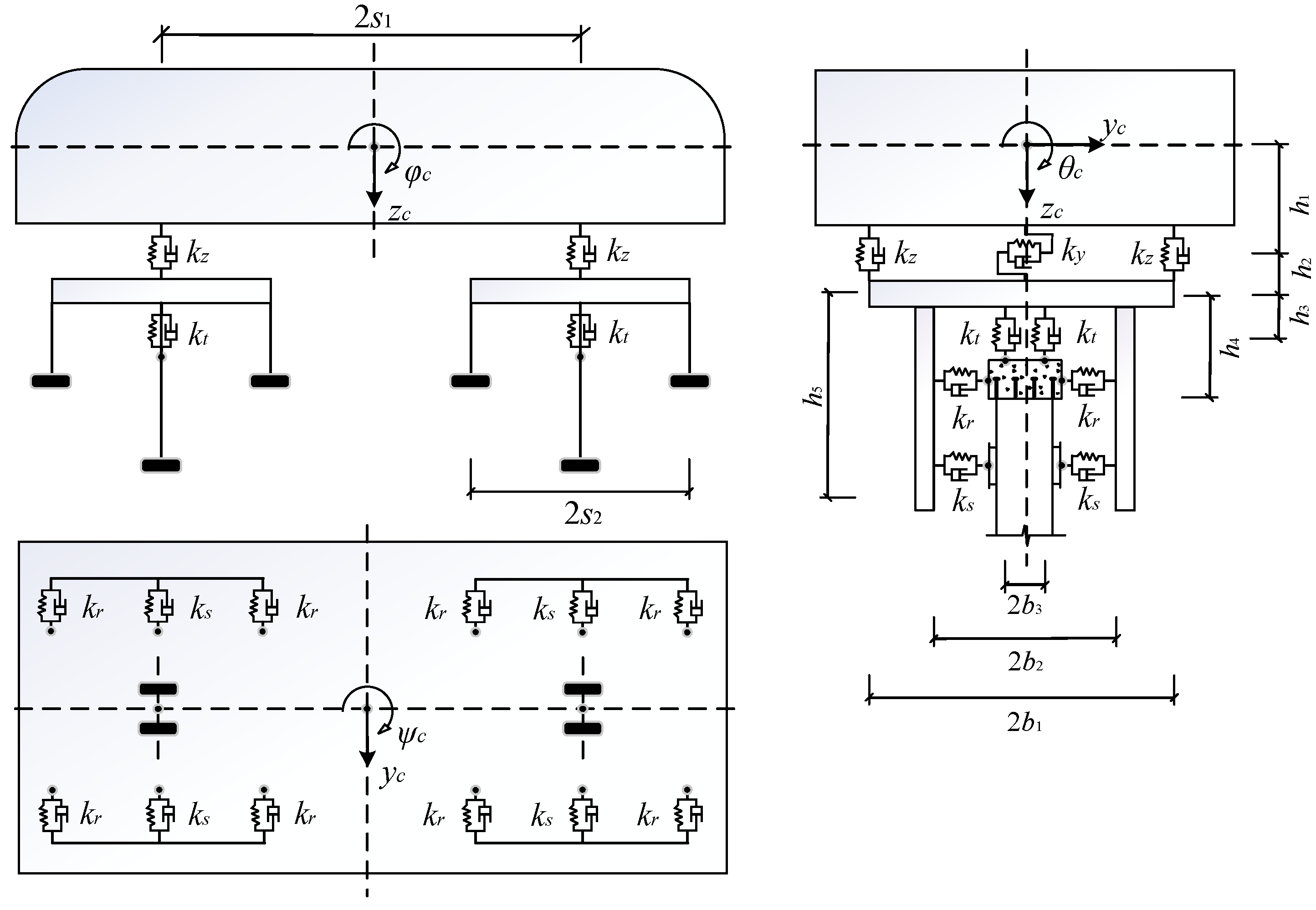
2.1. Train Model
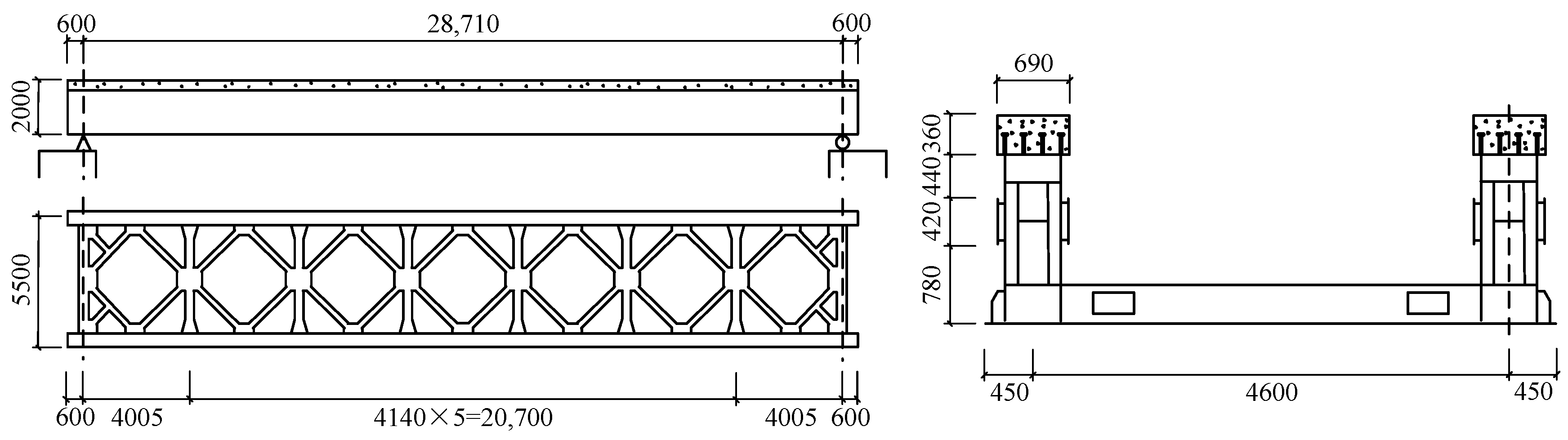
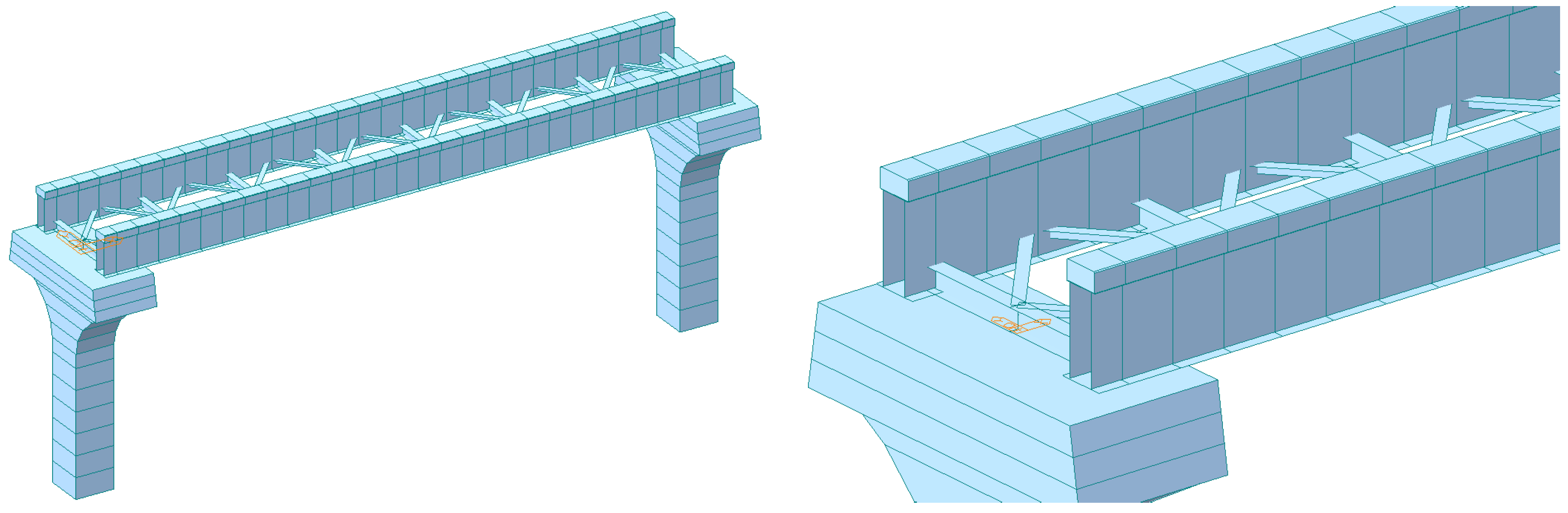
2.2. Bridge Model
2.3. Interaction Equations
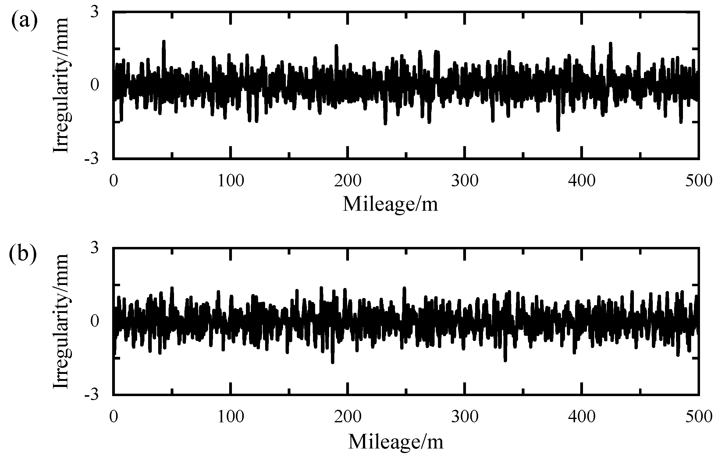
2.4. Track Irregularity
3. Numerical Results and Discussions
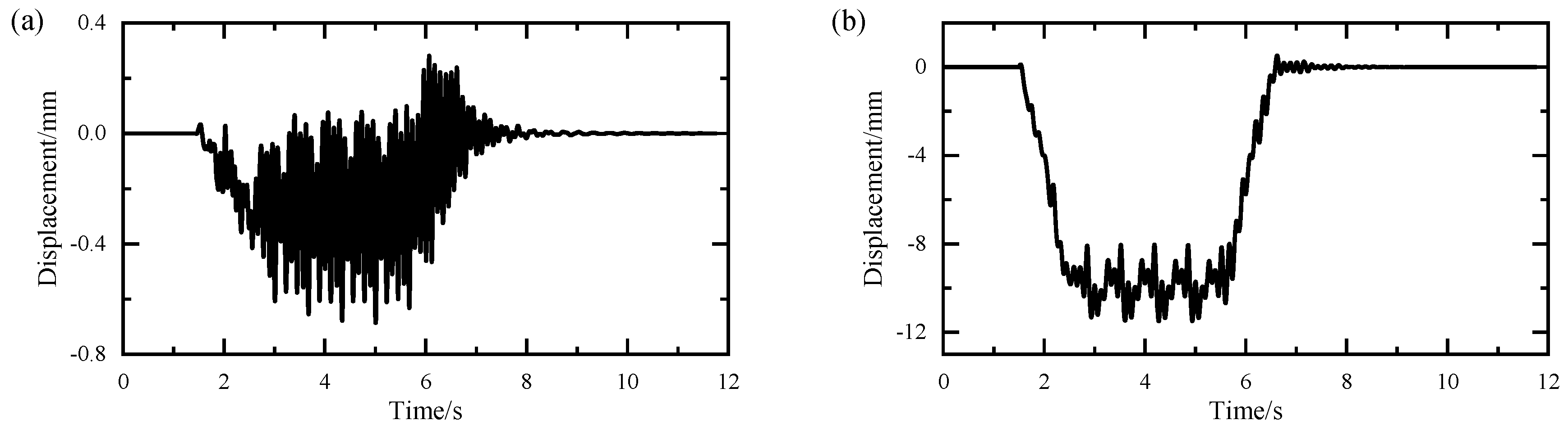
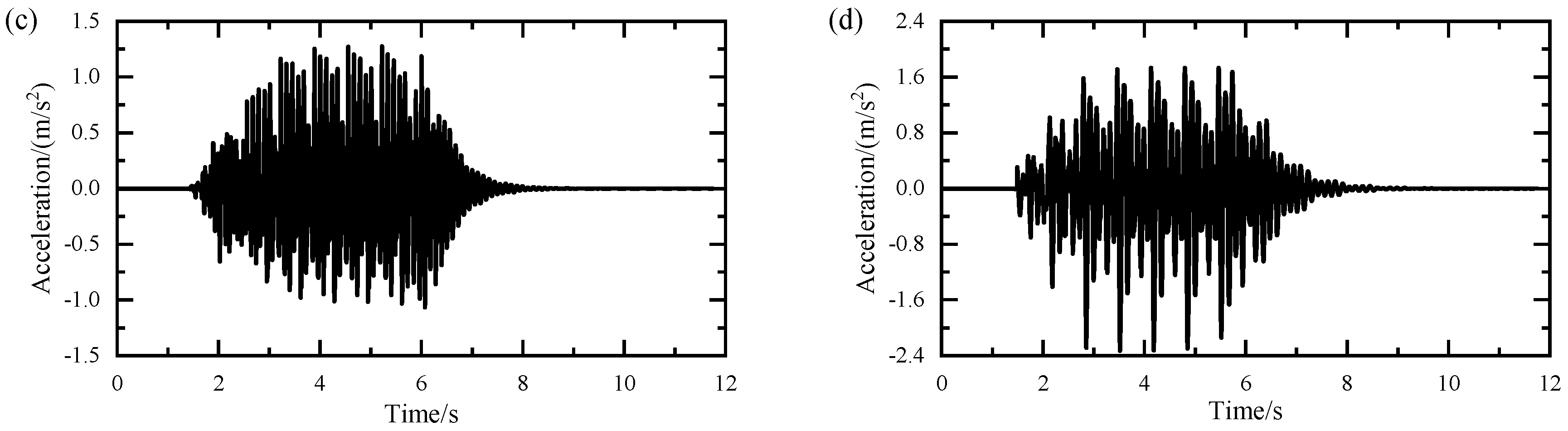
3.1. Time History Response
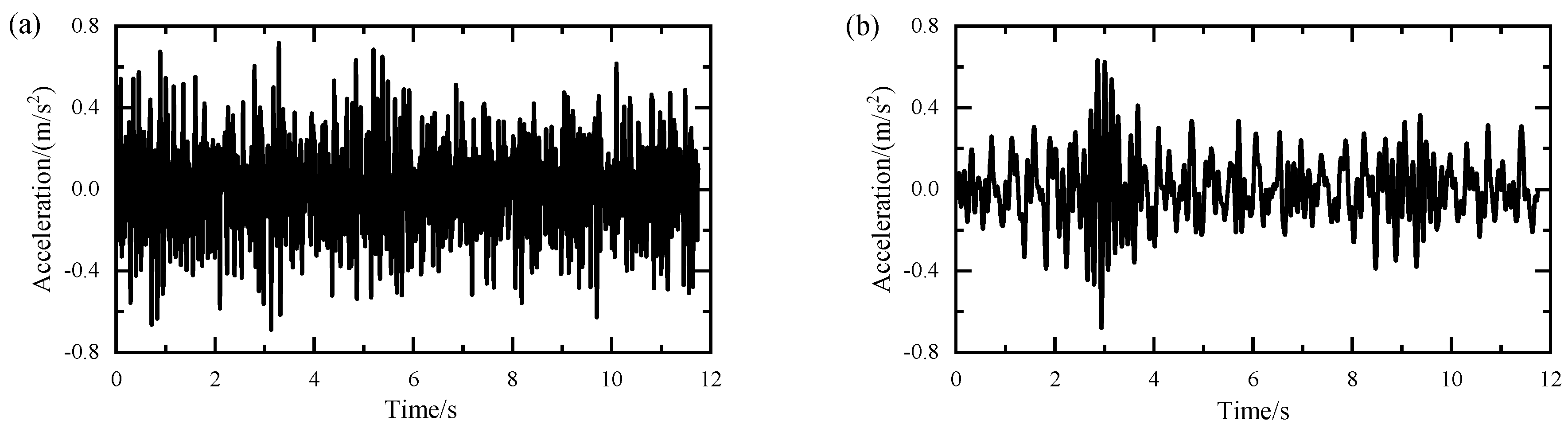
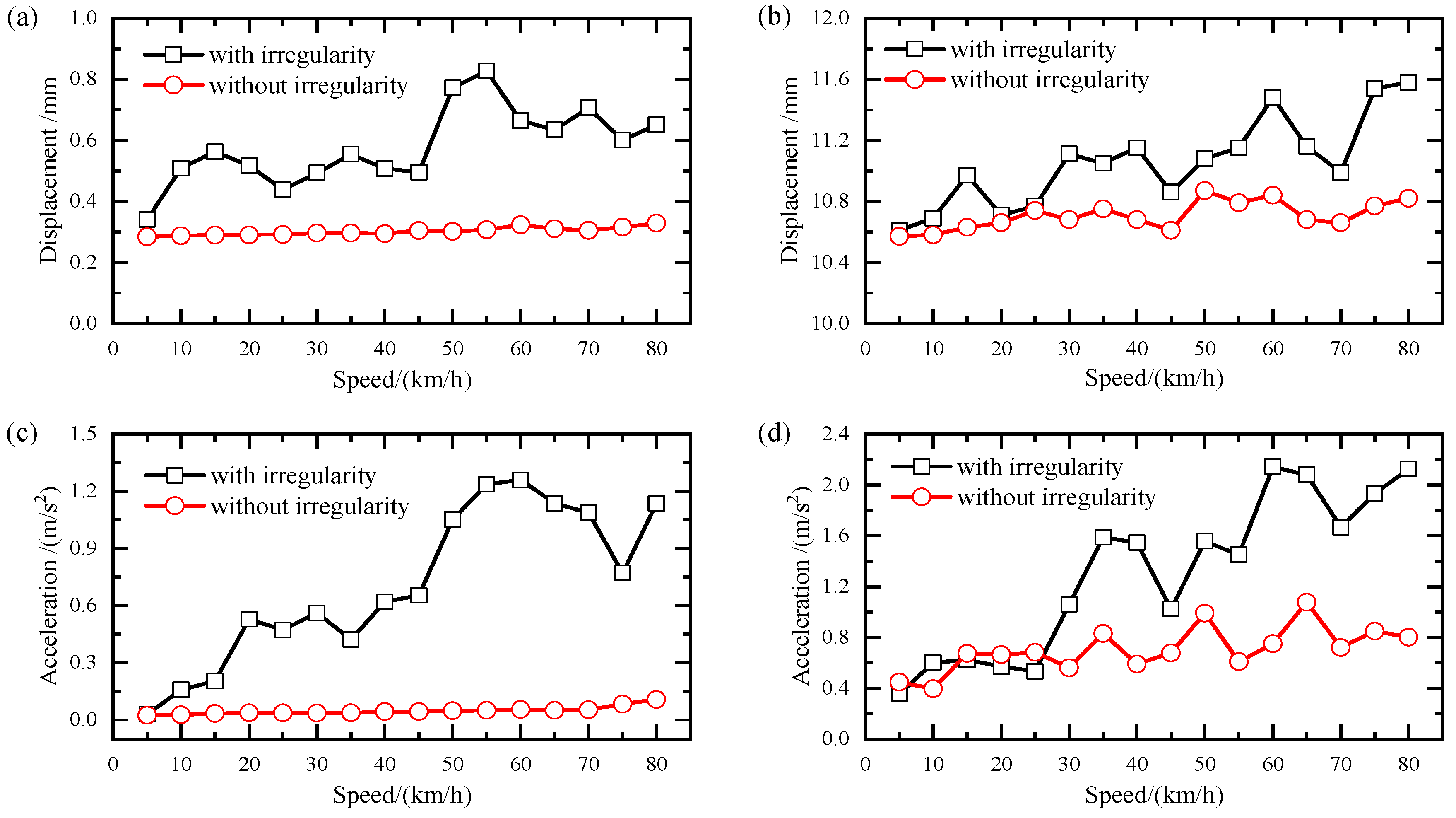
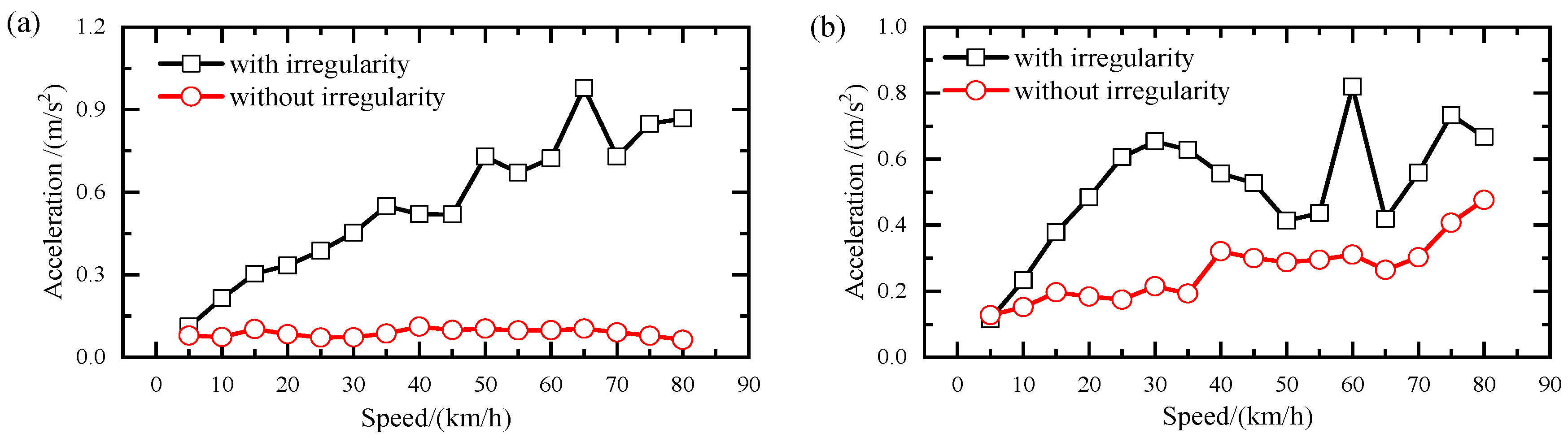
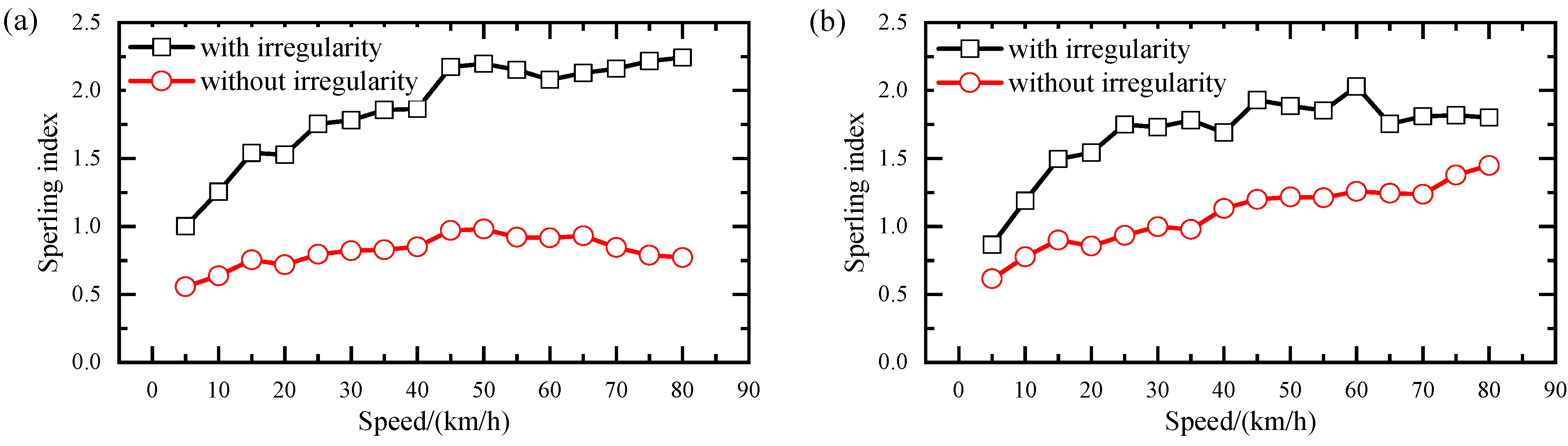
3.2. Track Irregularity Effect
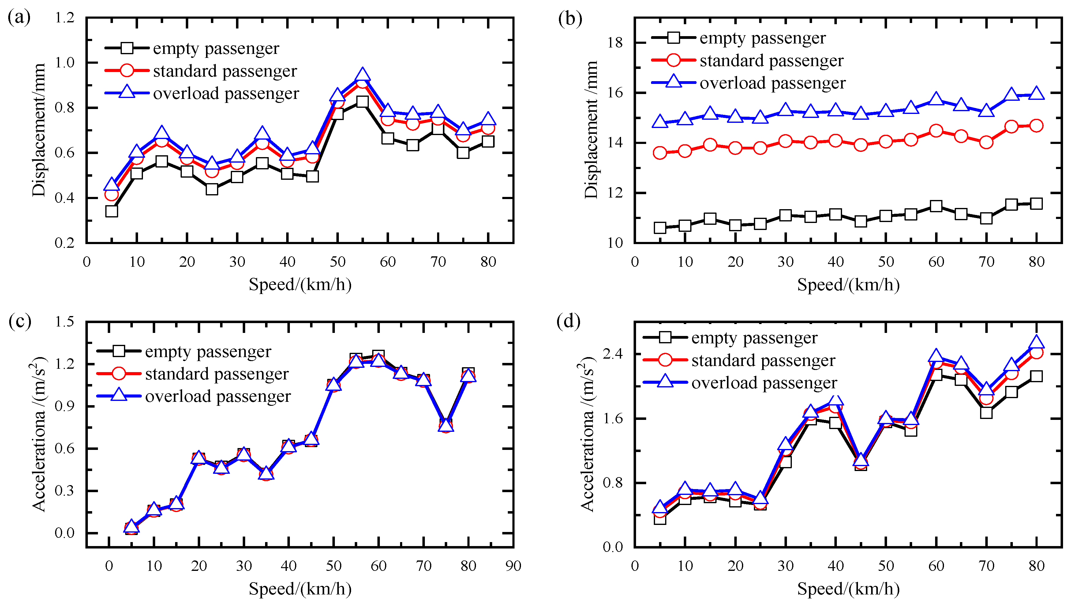
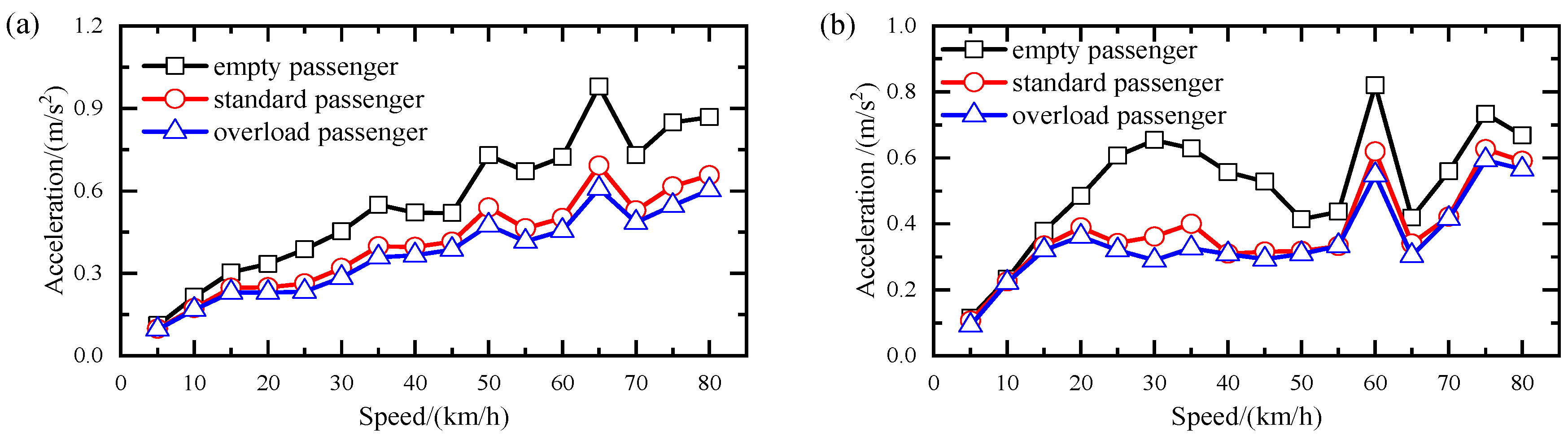
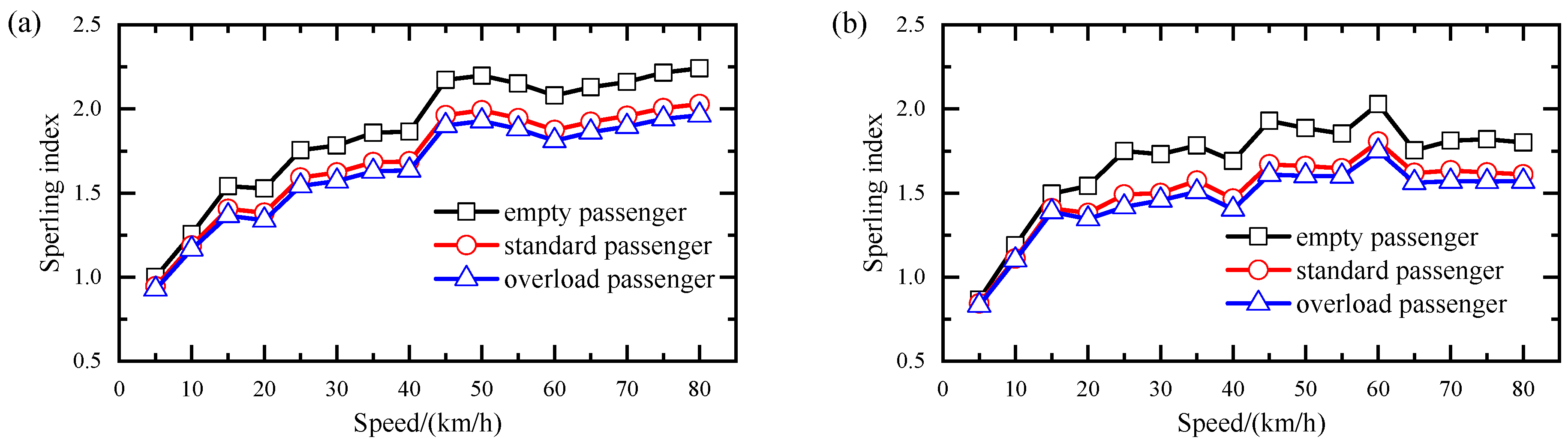
3.3. Passenger Load Effect
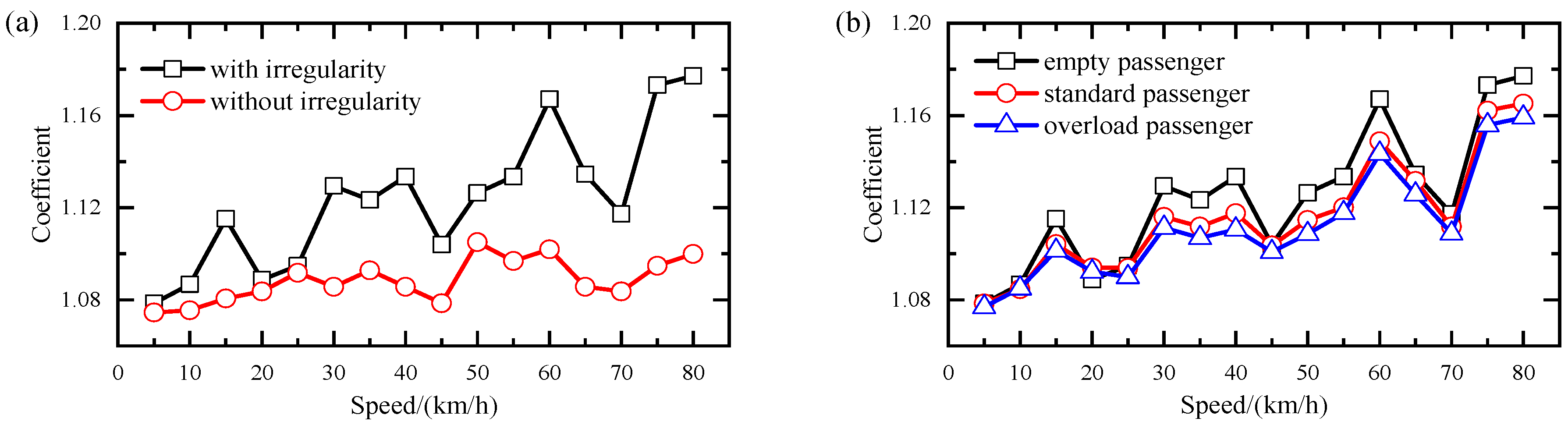
3.4. Impact Coefficients
3.5. Riding Comfort
4. Conclusions and Further Works
Author Contributions
Funding
Data Availability Statement
Conflicts of Interest
References
- Bhattacharjee, S.; Goetz, A.R. The rail transit system and land use change in the Denver metro region. J. Transp. Geogr. 2016, 54, 440–450. [Google Scholar] [CrossRef]
- He, X. Application and prospect of straddle monorail transit system in China. Urban Rail Transit 2015, 1, 26–34. [Google Scholar] [CrossRef]
- Gao, Q.; Cui, K.; Li, Z.; Li, Y. Numerical investigation of the dynamic performance and riding comfort of a straddle-type monorail subjected to moving trains. Appl. Sci. 2020, 10, 5258. [Google Scholar] [CrossRef]
- Wang, H.; Zhu, E.; Chen, Z. Dynamic response analysis of the straddle-type monorail bridge–vehicle coupling system. Urban Rail Transit 2017, 3, 172–181. [Google Scholar] [CrossRef]
- Zhai, W.M.; Cai, C.B. Train/track/bridge dynamic interactions: Simulation and applications. Veh. Syst. Dyn. 2002, 37 (Suppl. S1), 653–665. [Google Scholar] [CrossRef]
- Xia, H.; Zhang, N. Dynamic analysis of railway bridge under high-speed trains. Comput. Struct. 2005, 83, 1891–1901. [Google Scholar] [CrossRef]
- Zhang, N.; Xia, H.; Guo, W.; De Roeck, G. A vehicle–bridge linear interaction model and its validation. Int. J. Struct. Stab. Dyn. 2010, 10, 335–361. [Google Scholar] [CrossRef]
- Zhang, Z.C.; Lin, J.H.; Zhang, Y.H.; Howson, W.P.; Williams, F.W. Non-stationary random vibration analysis of three-dimensional train–bridge systems. Veh. Syst. Dyn. 2010, 48, 457–480. [Google Scholar] [CrossRef]
- Mao, J.; Yu, Z.; Xiao, Y.; Jin, C.; Bai, Y. Random dynamic analysis of a train-bridge coupled system involving random system parameters based on probability density evolution method. Probabilistic Eng. Mech. 2016, 46, 48–61. [Google Scholar] [CrossRef]
- Carbonari, S.; Nicoletti, V.; Martini, R.; Gara, F. Dynamics of bridges during proof load tests and determination of mass-normalized mode shapes from OMA. Eng. Struct. 2024, 310, 118111. [Google Scholar] [CrossRef]
- Du, X.T.; Xu, Y.L.; Xia, H. Dynamic interaction of bridge–train system under non-uniform seismic ground motion. Earthq. Eng. Struct. Dyn. 2012, 41, 139–157. [Google Scholar] [CrossRef]
- Guo, X.; Tang, J. Effects of wind barrier porosity on the coupled vibration of a train-bridge system in a crosswind. Struct. Eng. Int. 2019, 29, 268–275. [Google Scholar] [CrossRef]
- Li, Y.; Qiang, S.; Liao, H.; Xu, Y.L. Dynamics of wind–rail vehicle–bridge systems. J. Wind Eng. Ind. Aerodyn. 2005, 93, 483–507. [Google Scholar] [CrossRef]
- Montenegro, P.A.; Barbosa, D.; Carvalho, H.; Calçada, R. Dynamic effects on a train-bridge system caused by stochastically generated turbulent wind fields. Eng. Struct. 2020, 211, 110430. [Google Scholar] [CrossRef]
- Xia, C.Y.; Xia, H.; De Roeck, G. Dynamic response of a train–bridge system under collision loads and running safety evaluation of high-speed trains. Comput. Struct. 2014, 140, 23–38. [Google Scholar] [CrossRef]
- Xiang, P.; Ma, H.; Zhao, H.; Jiang, L.; Xu, S.; Liu, X. Safety analysis of train-track-bridge coupled braking system under earthquake. Structures 2023, 53, 1519–1529. [Google Scholar] [CrossRef]
- Yao, Z.; Zhang, N.; Zhu, M.; Li, X. Dynamic Interaction Analysis and Running Safety Assessment of the Wind–Train–Bridge System Considering the Moving Train’s Aerodynamic Coupling with Crosswind. Int. J. Struct. Stab. Dyn. 2023, 23, 2350173. [Google Scholar] [CrossRef]
- Žitný, J.; Ryjáček, P.; Sýkora, M.; Pospíšil, S.; Hračov, S. Probabilistic Assessment of the Equilibrium of a Steel Railway Bridge Based on Wind Tunnel and Traffic Records. Struct. Eng. Int. 2023, 34, 34–44. [Google Scholar] [CrossRef]
- Lee, C.H.; Kim, C.W.; Kawatani, M.; Nishimura, N.; Kamizono, T. Dynamic response analysis of monorail bridges under moving trains and riding comfort of trains. Eng. Struct. 2005, 27, 1999–2013. [Google Scholar] [CrossRef]
- Lee, C.H.; Kawatani, M.; Kim, C.W.; Nishimura, N.; Kobayashi, Y. Dynamic response of a monorail steel bridge under a moving train. J. Sound Vib. 2006, 294, 562–579. [Google Scholar] [CrossRef]
- Kim, C.W.; Kawatani, M. Effect of train dynamics on seismic response of steel monorail bridges under moderate ground motion. Earthq. Eng. Struct. Dyn. 2006, 35, 1225–1245. [Google Scholar] [CrossRef]
- Naeimi, M.; Tatari, M.; Esmaeilzadeh, A.; Mehrali, M. Dynamic interaction of the monorail–bridge system using a combined finite element multibody-based model. Proc. Inst. Mech. Eng. Part K J. Multi-Body Dyn. 2015, 229, 132–151. [Google Scholar] [CrossRef]
- Zhang, R.; Ji, Y.; Ren, L. Pre-load on the guiding/stabilizing wheels and the critical lateral force of a straddle-type monorail vehicle. Proc. Inst. Mech. Eng. Part F J. Rail Rapid Transit 2019, 233, 160–169. [Google Scholar] [CrossRef]
- Gou, H.; Zhou, W.; Yang, C.; Bao, Y.; Pu, Q. Dynamic response of a long-span concrete-filled steel tube tied arch bridge and the riding comfort of monorail trains. Appl. Sci. 2018, 8, 650. [Google Scholar] [CrossRef]
- Yang, Z.; Du, Z.; Xu, Z.; Zhou, J.; Hou, Z. Research on dynamic behavior of train dynamic model of straddle-type monorail. Noise Vib. Worldw. 2020, 51, 195–207. [Google Scholar] [CrossRef]
- Jiang, Y.; Zhong, W.; Wu, P.; Zeng, J.; Zhang, Y.; Wang, S. Prediction of wheel wear of different types of articulated monorail based on co-simulation of MATLAB and UM software. Adv. Mech. Eng. 2019, 11, 1687814019856841. [Google Scholar] [CrossRef]
- Zhou, J.; Du, Z.; Yang, Z.; Xu, Z. Dynamic parameters optimization of straddle-type monorail vehicles based multiobjective collaborative optimization algorithm. Veh. Syst. Dyn. 2020, 58, 357–376. [Google Scholar] [CrossRef]
- Sirisonthi, A.; Suparp, S.; Joyklad, P.; Hussain, Q.; Julphunthong, P. Experimental study of the load-deformation behaviour of the precast post-tensioned continuous girder for straddle monorail: Full-scale load test under service and ultimate loading conditions. Case Stud. Constr. Mater. 2021, 15, e00666. [Google Scholar] [CrossRef]
- Zhou, J.; Huang, C.; Deng, J.; Zhang, J.; Zhang, L. A co-simulation approach for straddle monorail vehicle–bridge interaction subjected to nonlinear excitation. Adv. Eng. Softw. 2023, 180, 103458. [Google Scholar] [CrossRef]
- Chang, K.C.; Kim, C.W.; Borjigin, S. Variability in bridge frequency induced by a parked vehicle. Smart Struct. Syst. 2014, 13, 755–773. [Google Scholar] [CrossRef]
- Zhang, N.; Xia, H. Dynamic analysis of coupled vehicle–bridge system based on inter-system iteration method. Comput. Struct. 2013, 114, 26–34. [Google Scholar] [CrossRef]
- GB/T-5599-2019; Specification for Dynamic Performance Assessment and Testing Verification of Rolling Stock. Standardization Administration: Beijing, China, 2019.
- Wu, Z.; Zhang, N.; Yao, J.; Poliakov, V. Analysis of Train Car-Body Comfort Zonal Distribution by Random Vibration Method. Appl. Sci. 2022, 12, 7442. [Google Scholar] [CrossRef]


| Rigid | Transverse | Vertical | Rolling | Pitching | Yawing |
|---|---|---|---|---|---|
| Car body | yc | zc | θc | φc | ψc |
| Bogie (j = 1, 2) | ytj | ztj | θtj | - | ψtj |
| Parameters | Notation | Unit | Value |
|---|---|---|---|
| Car body mass | mc | kg | 14,220 |
| Car body x-inertia moment | Ixc | kg∙m2 | 19,970 |
| Car body y-inertia moment | Iyc | kg∙m2 | 171,700 |
| Car body z-inertia moment | Iyc | kg∙m2 | 171,700 |
| Bogie mass | mt | kg | 6200 |
| Bogie x-inertia moment | Ixt | kg∙m2 | 2461 |
| Bogie y-inertia moment | Iyt | kg∙m2 | 9688 |
| Bogie z-inertia moment | Iyt | kg∙m2 | 3488 |
| Transverse stiffness of the suspension system | ky | kN/m | 490,000 |
| Vertical stiffness of the suspension system | kz | kN/m | 900,000 |
| Transverse damping of the suspension system | cy | kN∙s/m | 166,800 |
| Vertical damping of the suspension system | cz | kN∙s/m | 22,800 |
| Stiffness of the traveling wheel | kt | kN/m | 6,370,000 |
| Stiffness of the steering wheel | kr | kN/m | 6,370,000 |
| Stiffness of the stabilizing wheel | ks | kN/m | 5,170,000 |
| Damping of the traveling wheel | cw | kN∙s/m | 185,500 |
| Damping of the steering wheel | cr | kN∙s/m | 185,500 |
| Damping of the stabilizing wheel | cs | kN∙s/m | 26,100 |
| Longitudinal distance of bogies | s1 | m | 9.6 |
| Longitudinal distance of the steering wheel | s2 | m | 2.5 |
| Transverse distance of the suspension system | b1 | m | 2.05 |
| Transverse distance of the steering and stabilizing wheels | b2 | m | 1.58 |
| Transverse distance of the traveling wheel | b3 | m | 0.4 |
| Vertical distance between the car body and suspension system | h1 | m | 0.6 |
| Vertical distance between the bogie and suspension system | h2 | m | 0.285 |
| Vertical distance between the bogie and traveling wheel | h3 | m | 0.115 |
| Vertical distance between the bogie and steering wheel | h4 | m | 0.63 |
| Vertical distance between the bogie and stabilizing wheel | h5 | m | 1.715 |
| Mode NO. | Frequency/Hz | Mode Description | Mode Shape |
|---|---|---|---|
| 1 | 3.323 | Transverse (piers have same phase) | 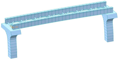 |
| 2 | 4.256 | Transverse (piers have reverse phase) | 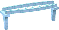 |
| 3 | 5.771 | Vertical (only track beams) | 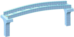 |
| 4 | 7.338 | Torsional (only track beams) | 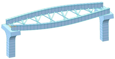 |
| 5 | 8.853 | Transverse (only track beams) | 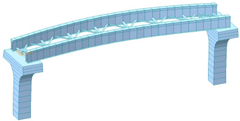 |
| Vertical | Horizontal | ||
|---|---|---|---|
| 0.5 < f ≤ 5.9 Hz | F(f) = 0.325f2 | 0.5 < f ≤ 5.4 Hz | F(f) = 0.8f2 |
| 5.9 < f ≤ 20 Hz | F(f) = 400/f2 | 5.4 < f ≤ 26 Hz | F(f) = 650/f2 |
| f > 20 Hz | F(f) = 1 | f > 26 Hz | F(f) = 1 |
| W | Comfort (Vibration Sensitivity) |
|---|---|
| 1 | Slight feeling |
| 2 | Obvious feeling |
| 2.5 | Not uncomfortable feeling |
| 3 | Uncomfortable feeling but bearable |
| 3.25 | Very uncomfortable feeling |
| 3.5 | Extremely uncomfortable feeling and not bearable for long |
| 4 | Unpleasant and unhealthy to bear for a long time |
Disclaimer/Publisher’s Note: The statements, opinions and data contained in all publications are solely those of the individual author(s) and contributor(s) and not of MDPI and/or the editor(s). MDPI and/or the editor(s) disclaim responsibility for any injury to people or property resulting from any ideas, methods, instructions or products referred to in the content. |
© 2025 by the authors. Licensee MDPI, Basel, Switzerland. This article is an open access article distributed under the terms and conditions of the Creative Commons Attribution (CC BY) license (https://creativecommons.org/licenses/by/4.0/).
Share and Cite
Yao, Z.; Liu, Z.; Zhong, Z. A Dynamic Interaction Analysis of a Straddle Monorail Train and Steel–Concrete Composite Bridge. Buildings 2025, 15, 2333. https://doi.org/10.3390/buildings15132333
Yao Z, Liu Z, Zhong Z. A Dynamic Interaction Analysis of a Straddle Monorail Train and Steel–Concrete Composite Bridge. Buildings. 2025; 15(13):2333. https://doi.org/10.3390/buildings15132333
Chicago/Turabian StyleYao, Zhiyong, Zongchao Liu, and Zilin Zhong. 2025. "A Dynamic Interaction Analysis of a Straddle Monorail Train and Steel–Concrete Composite Bridge" Buildings 15, no. 13: 2333. https://doi.org/10.3390/buildings15132333
APA StyleYao, Z., Liu, Z., & Zhong, Z. (2025). A Dynamic Interaction Analysis of a Straddle Monorail Train and Steel–Concrete Composite Bridge. Buildings, 15(13), 2333. https://doi.org/10.3390/buildings15132333