Abstract
Abrasive waterjet technology is a promising sustainable and green technology for cutting underground structures. Abrasive waterjet usage in demolition promotes sustainable and green construction practices by reduction of noise, dust, secondary waste, and disturbances to the surrounding infrastructure. In this study, a numerical framework based on a coupled Smoothed Particle Hydrodynamics (SPH)–Finite Element Method (FEM) algorithm incorporating the Riedel–Hiermaier–Thoma (RHT) constitutive model is proposed to investigate the damage mechanism of concrete subjected to abrasive waterjet. Numerical simulation results show a stratified damage observation in the concrete, consisting of a crushing zone (plastic damage), crack formation zone (plastic and brittle damage), and crack propagation zone (brittle damage). Furthermore, concrete undergoes plastic failure when the shear stress on an element exceeds 5 MPa. Brittle failure due to tensile stress occurs only when both the maximum principal stress (σ1) and the minimum principal stress (σ3) are greater than zero at the same time. The damage degree () of the concrete is observed to increase with jet diameter, concentration of abrasive particles, and velocity of jet. A series of orthogonal tests are performed to analyze the influence of velocity of jet, concentration of abrasive particles, and jet diameter on the damage degree and impact depth (h). The parametric numerical studies indicates that jet diameter has the most significant influence on damage degree, followed by abrasive concentration and jet velocity, respectively, whereas the primary determinant of impact depth is the abrasive concentration followed by jet velocity and jet diameter. Based on the parametric analysis, two optimized abrasive waterjet configurations are proposed: one tailored for rock fragmentation in tunnel boring machine (TBM) operations; and another for cutting reinforced concrete piles in shield tunneling applications. These configurations aim to enhance the efficiency and sustainability of excavation and tunneling processes through improved material removal performance and reduced mechanical wear.
1. Introduction
The rapid urbanization and development of modern technology has created the need for the demolition or modification of existing structures to adapt to new structures. In China alone, the newly added mileage of urban rail transit will exceed 5000 km in the next five years [1]. Among urban rail transit modes, the subway will still be the main force, with an estimated newly added mileage of approximately 3000 km. During the shield tunneling process, it is inevitable to encounter pile foundations [2]. These piles often need to be demolished or cut to make a way for new construction. The demolition process often creates noise pollution, air pollution because of dust, and huge quantities of waste. These practices often do not align with green and sustainable construction practices. In such scenarios, one of the alternative solutions for demolition is use of an abrasive waterjet. Abrasive waterjets are formed when a combination of high-speed water and abrasive particles jets through a sand mixing tube; it has been widely used in the field of mining, rock breaking by Tunnel Boring Machine (TBM), and oil drilling. Recently, the application of abrasive waterjet in the field of building demolition and concrete repair has been increasing due to its outstanding cutting behavior. The use of abrasive waterjet in demolition provides a green and sustainable solution. The abrasive waterjet technology, when used in demolition, provides reduced dust, noise and secondary waste, which aligns with green demolition practices. In tunneling, the technology of direct shield cutting with abrasive waterjet has been adopted; this technology promotes sustainable development in multiple aspects. Compared with the traditional mechanical pile-cutting method, this technology can accurately cut the pile body and generates relatively low noise during the working process, which helps to create a quiet living and working environment. It has a relatively small vibration impact on the surrounding strata and buildings, protecting the stability of infrastructure, such as nearby underground pipelines and building foundations, and realizing green and environmentally friendly construction processes. Many methods, such as computerized tomography, scanning electron microscopy, and acoustic emission technology, have been employed to study crack propagation and the damage mechanism of concrete subjected to abrasive waterjet [3]. Based on the fast Fourier transform, the crushing behavior of the concrete has been studied through acoustic emission technology [4].
Because the nonlinear dynamic collision and liquid–solid coupling are complex, the crushing behavior of the concrete is transient, and the concrete is nontransparent, the damage mechanism of concrete subjected to abrasive waterjet is not clearly understood. Due to the advancement of computation capacity, numerical simulation has become an effective way to study concrete subjected to abrasive waterjet [5]. A model of concrete subjected to abrasive waterjet was established through the Smoothed Particle Hydrodynamics (SPH) method and the effects of the concrete compressive strength and concentration of abrasive particles on the impact force, crushing, and damage efficiency were studied [6]. A new SPH–Finite Element Method (FEM) coupling model was established [7], in which abrasive particles (steel balls) generated by the FEM were dispersed in the water generated by the SPH. The simulation results indicated that the impact dynamic load caused by the stress wave led to the damage of concrete and the obvious local effect caused by the stress wave was found. Jiang et al. [8] simulated the rock damage process using the SPH–FEM algorithm and investigated the rock damage state subjected to continuous and discontinuous waterjet. The failure mechanism of rock has been studied through the variation of stress and damage degree along with time. Xue et al. [9] investigated the impact of waterjet on coal using the Johnson–Holmquist concrete (JHC) model, and found that the breaking process subjected to abrasive waterjet was more efficient than that subjected to waterjet. Meanwhile, to promote intelligent and sustainable construction, interdisciplinary techniques are increasingly introduced into tunneling engineering applications. In particular, advanced computational models from computer science are proving valuable for optimizing abrasive waterjet processes [10,11,12]. Federated learning and confidence-based decision-making frameworks, for example, can support real-time control and parameter adjustment during shield tunneling [13,14]. Moreover, fuzzy evaluation methods and similarity-based multi-criteria systems enable the efficient selection of jet parameters such as velocity and abrasive concentration, balancing cutting performance and environmental impact [15,16]. Lightweight neural models based on edge computing further enhance safety and precision by enabling real-time monitoring and anomaly detection [17]. These advances provide promising tools to improve the sustainability and intelligence of abrasive waterjet technology. A recent study also demonstrated that tunneling parameters combined with signal-processing techniques can effectively predict TBM cutterhead wear, further highlighting the role of intelligent models in excavation control [18]. Despite these advancements, significant gaps remain in understanding the mechanism of rock, concrete, and coal breaking subjected to waterjet from different perspectives; shortcomings still exist. For instance, regarding important jet parameters (i.e., the velocity of the waterjet, jet diameter, and concentration of abrasive particles), few studies have interpreted the effect of these parameters on the impacting effect comprehensively; their contributions to concrete damage have not been quantitatively analyzed. Furthermore, the abrasive particles modeled in existing models are simply SPH particles or rigid bodies, which ignores the fact that the abrasive particles are crushed when they impact on the concrete.
This study addresses these limitations by simulating the breaking process of concrete subjected to abrasive waterjet with the SPF-FEM coupling algorithm. In this model, water is represented by SPH particles; abrasive particles and concrete are established with the FEM mesh. First, the Riedel–Hiermaier–Thoma (RHT) model is validated by simulating the crack propagation and damage evolution of concrete subjected to abrasive waterjet. Then, the damage degree (, the overall damage degree of the waterjet impacting the concrete) and impact depth (h, the maximum depth of the concrete impacted by abrasive waterjet) are selected as response parameters. The effects of the velocity of the jet, the concentration of abrasive particles, and jet diameter on concrete damage are studied based on orthogonal tests. Finally, the optimum configurations for different shield construction backgrounds are proposed according to the significance analysis of three jet parameters. The proposed model contributes to more efficient and sustainable construction practices.
2. Theory and Model Description
2.1. SPH–FEM Coupling Algorithm
A series of particles are used to express the continuum materials in SPH. Particles established in the model could be a good solution to deal with large deformation and multifluid problems [19,20]. FEM is suitable for simulating the mechanical behavior of solid materials and can solve the boundary problem effectively and improve computation capacity [21]. The coupling SPH–FEM model has the advantage of each method and can solve the fluid–structure interaction effectively; it has been widely used recently.
The computation flow chart of the coupling SPH–FEM model is shown in Figure 1. The computation process of SPH is shown in the left part of the figure while that of the FEM is shown in the right part of the figure. The nodes-to-surface contact algorithm is used in the SPH–FEM coupling algorithm [22]. Waterjet is defined as the slave surface by the SPH method while concrete is defined as the master surface by the FEM method. This is because the concrete domain is stiffer and meshed with FEM, providing a stable contact surface, while the SPH-based waterjet requires flexible contact tracking and is therefore set as the slave.
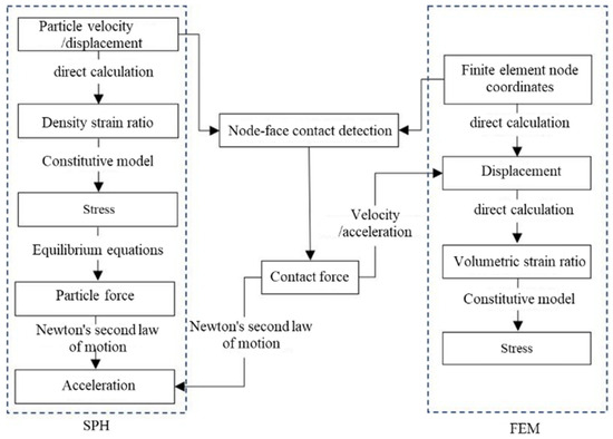
Figure 1.
SPH–FEM coupling algorithm.
2.2. Constitutive Model of Concrete
Under impact, the mechanical behavior of concrete is significantly changed due to the high strain rate of the material. Thus, a constitutive model that accounts for the high strain rate effect should be employed. The RHT model, developed by Riedel et al. [23], is a macro-scale material model capable of simulating the actual mechanical behavior of concrete under impact. Compared to other constitutive models, the RHT model considers the large stress, high strain rate, and high pressure of concrete; it can also predict both the elastic stage and the damage failure stage of the concrete [24]. The RHT model considers three pressure-dependent surfaces on the stress space (i.e., the elastic limit surface, failure surface, and residual surface for the crushing material), as shown in Figure 2. In addition, stress hardening, strain hardening, strain-rate hardening, strain softening, and third invariant dependence for compressive and tensile meridians are also taken into account in the RHT model. The mechanical behavior of the post-yield concrete is characterized by strain hardening, and that of post-failure concrete is characterized by damage.
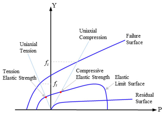
Figure 2.
Strength surfaces defined for concrete material in the RHT model.
The failure surface function is described as follows:
where is failure stress, is the equivalent stress on the meridian, is the rate-dependent enhancement factor, and is the function of the lode angle θ. Detailed expressions are shown as follows:
where * refers to a normalization by the unconfined uniaxial compression strength (), , N, BQ, and Q0 are material constants, is the normalized pressure, is the normalized spall strength, α and δ are the compressive strain rate factor and tensile strain rate factor, respectively. is the stress rate, and is initial strain rate. Q2 is the ratio of the tensile to the compressive meridian. and are second and third invariants of the deviatoric stress. rt and rc are the deviatoric stress at the meridian of tension and compression, respectively.
Damage value Da is an accumulation function in the RHT model, which represents the high strain rate damage in the concrete, as follows:
where is the equivalent plastic strain in a damage accumulating step, represents the total plastic strain of the concrete under the hydrostatic pressure, is the normalized maximum tensile strength of concrete, and D1 and D2 are the shape parameters to describe the post-failure behavior of the concrete.
2.3. Numerical Model
The concrete model subjected to abrasive waterjet is established, in which the concrete is regarded as the homogeneous material (Figure 3). To achieve a balance between computational efficiency and physical realism, a 2D plane stress model is employed. Although a full 3D model could provide more detailed representation of the stress wave propagation and crack evolution, the 2D plane stress model is widely accepted for the preliminary investigation of impact damage, especially when the out-of-plane stress components are relatively small compared to the in-plane responses. In the 2D plane stress model, the concrete model is simplified as a rectangle with a length of 80 mm and width of 50 mm; the abrasive particles are round, with a diameter of 0.8 mm, both of which are Lagrange meshes. To simulate the evolution of the damage for concrete subjected to abrasive waterjet, a large amount of the elements (308,828) are established through the FEM method. The length of these elements on the boundary is 0.2 mm with a 0.1 mm length for other parts. The waterjet is simplified as a rectangle with a length of 20 mm and a width of 2 mm, which is divided into 8000 SPH particles. Abrasive particles are established by the FEM mesh. To avoid the effect of the stress wave reflected from the free boundary during simulation, the bilateral and bottom sides of the concrete model are treated as non-reflective boundary conditions.

Figure 3.
Established model of concrete subjected to abrasive waterjet.
C35 concrete is adopted in the simulation; the key parameters used in the RHT model for concrete are summarized in Table 1. To describe the state of water, the Gruneisen function is used to describe its pressure and volumetric strain relation, shown as follows:
where P is the pressure state in water, μ is the volumetric strain, is the initial density, E0 is the initial energy, γ0 is the Gruneisen factor, c is the velocity of sound, and a, S1, S2, and S3 are material parameters. The parameters of water are summarized in Table 2.

Table 1.
Key parameters of RHT model.
Table 2.
Material parameters for water and abrasive particles.
As abrasive particles are broken upon impact with the concrete, they are defined as deformable bodies and a tensile failure criterion is employed. Specifically, once the maximum principal stress within an abrasive particle exceeds a threshold value, the element is eroded to simulate particle fragmentation. In this study, the threshold is set to 150 MPa, following the approach of Anwar et al. [25], who demonstrated that this value closely reflects the dynamic tensile strength of abrasives and yields accurate predictions of material removal behavior in SPH–FEM simulations. The abrasive particles, colored in garnet, are shown in Figure 3; the material parameters are summarized in Table 2 [25]. All computations and numerical simulations were performed using the commercial finite element software LS-DYNA (2007) in this paper [23,26,27].
2.4. Validation of the Model
For quantitative calibration, RHT parameters were fitted to high-strain-rate compression data (error <5%), SPH–FEM contact stiffness and damping were tuned to match Liu et al.’s [20] pit depth and ~45° crack angle (error <10%). To clearly observe the concrete crack and its development, Liu et al. [28] used black ink to highlight the development of cracks in the concrete specimens subjected to abrasive waterjet, shown in Figure 4. When the cracks developed, they were quickly dyed by the black ink; therefore, the areas dyed black refer to the crack zone and other parts refer to no cracks. It can be seen that the conical cracks were generated first in the crushing zone when concrete specimens were subjected to abrasive waterjet (Figure 4a). In the middle stage, the speed of the conical crack development slowed down, with a quick development of the longitudinal cracks (Figure 4b). In the final stage, both the longitudinal and the conical cracks became stable, with a very slow speed of development (Figure 4c); only the central crack was quickly developed. Such crack development mechanisms and processes coincide with the presented simulation results shown in Figure 4d–f. The crack development mechanism found in this paper is also similar to that simulated using the JHC constitutive model [9]. Hence, the RHT constitutive model used in this paper is capable of capturing the main features of crack development and damage behaviors of concrete subjected to abrasive waterjet.

Figure 4.
Crack development in both the experimental tests and numerical simulation.
3. Results and Discussion
3.1. Damage Mechanism of Concrete
Figure 5 shows that at the beginning of the waterjet impact (5 μs), the effect of “water hammer pressure” is formed and the concrete is under compression. Water hammer pressure refers to the initial transient pressure surge caused by the sudden deceleration of the high-speed waterjet upon contact with the concrete surface. Those parts of the concrete not impacted by the abrasive waterjet could resist the compression, which could induce shear damage. The crushing zone is formed in the contact surface between the abrasive waterjet and concrete, which is at an angle of 45 degrees to the concrete surface. At 12 μs, the abrasive particles start to impact the concrete. Then, the concrete is damaged quickly along with the impact direction of abrasive particles due to the large amount of kinetic energy carried by the abrasive particles. After the impact of the first abrasive particle (15 μs), a clear “crater” and two conical cracks are formed. With continual erosion by the abrasive waterjet, conical cracks continue to expand and the crushing zone is enlarged. Finally, the depth and width of the cavity develop rapidly and central and circumferential cracks are gradually formed. In the later stage of the waterjet impact, the conical cracks and crushing zone expand slowly, whereas central and circumferential cracks expand rapidly. It can be found that the sizes of the cavity and the crushing zone at 40 μs and 70 μs are similar, which indicates that the damage of the concrete impacted by the abrasive waterjet changes slowly. The concrete damage in the early middle period (40 μs) is dominated by the increase in the crushing zone and the expansion of conical cracks. The impact depth is mainly developed at this stage and increases slowly in the later stage. In the later stage of the abrasive waterjet (70 μs), concrete damage is dominated by circumferential and central crack expansion.
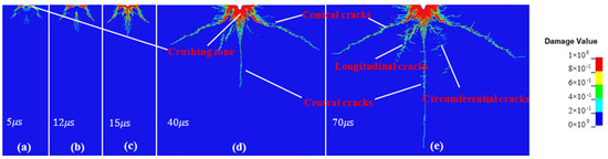
Figure 5.
Crack propagation of concrete subjected to abrasive particles at different waterjet impact (a) at 5 μs (b) at 12 μs (c) at 15 μs (d) at 40 μs (e) at 70 μs.
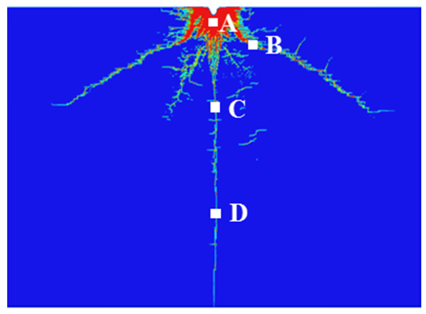
The cracks are shown in Figure 6; points A, B, C, and D are selected as monitoring points. The time history curves of maximum shear stress (τmax), maximum and minimum principal stresses (σ1 and σ3), and damage value Da (in which 0 is undamaged and 1 is fully damaged) for those points are shown in Figure 7. The observations described here are derived entirely from the numerical simulation results. Specifically, the stress wave propagation, damage accumulation, and failure patterns were evaluated at the four monitoring points (A–D) shown in Figure 6; their respective stress and damage histories are presented in Figure 7. These time history curves provide insight into how different regions of the concrete specimen evolve under abrasive waterjet impact. Point A, located closest to the impact surface, shows early plastic damage due to shear stress, while points B and C experience a transition from plastic to brittle failure. Point D, farther from the impact source, undergoes delayed tensile damage. This stage of damage behavior, visualized through simulation, enables classification of the concrete response into crushing, crack formation, and crack propagation zones based on numerical evidence.

Figure 6.
Layout of monitoring points A, B, C, and D.
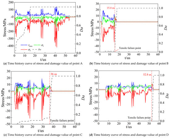
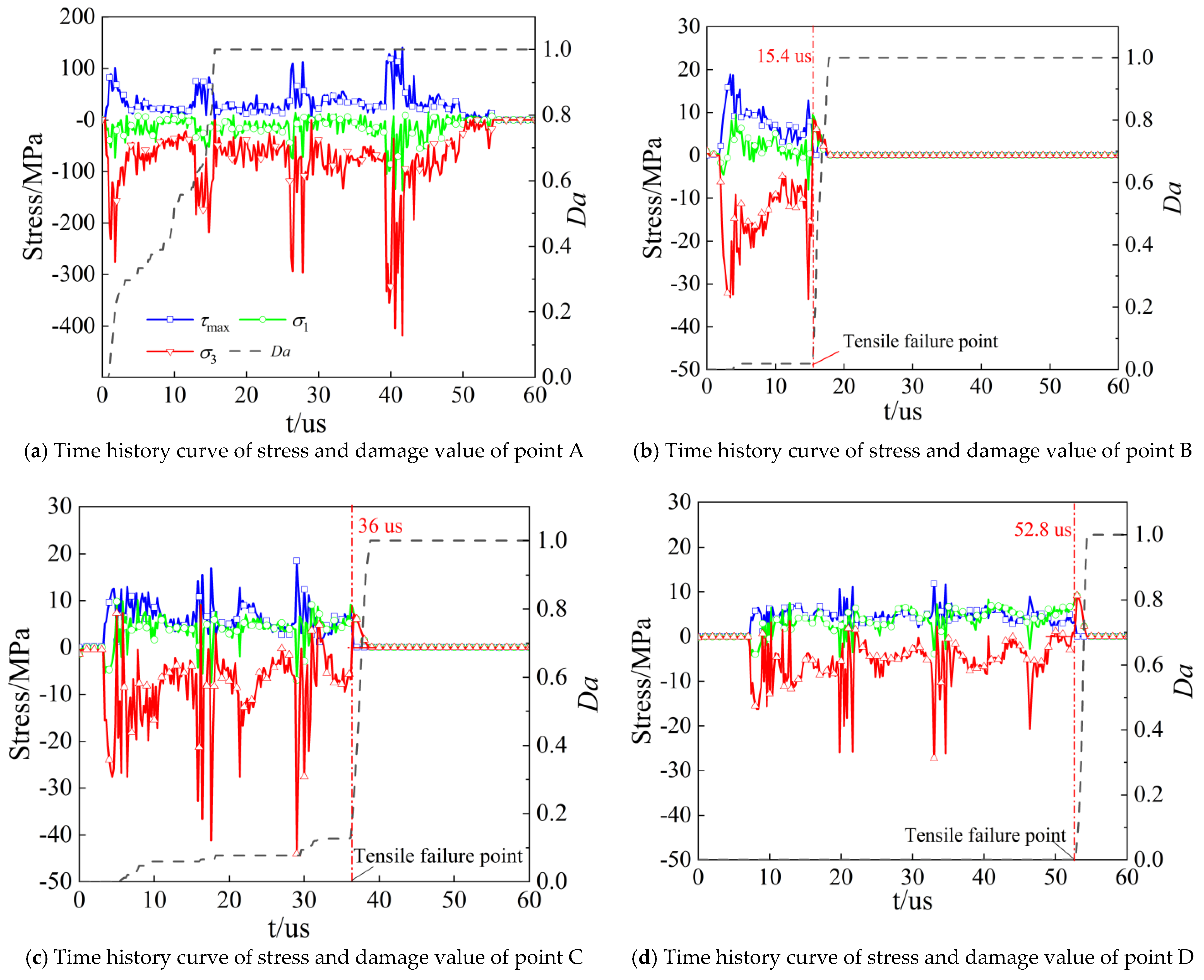
Figure 7.
Time history curves of stress and damage value of points A, B, C, and D.
It can be determined whether an element exhibits plastic or brittle damage by considering both the damage value Da and the stress state. In this study, when the maximum principal stress σ1 (or minimum principal stress σ3) is greater than zero, it indicates that the surface element is subjected to tensile stress; otherwise, it is under compressive stress. The stress wave first reaches point A, which is closest to the impact surface; the damage of point A starts from 10 μs with the maximum shear stress 80 MPa (Figure 7a). Then, the maximum shear stress increases rapidly to 100 MPa and the damage value significantly increases. Before 14.8 μs, the maximum shear stress decreases with a slowly increased damage value; after 14.8 μs, both the maximum shear stress and damage value increase rapidly. Finally, complete damage occurs. Figure 7a shows that at monitoring point A, both σ1 and σ3 are less than zero, indicating that point A is almost not subjected to tensile stress. Combined with the time history curve of the damage value Da, it can be concluded that the damage at this location is mainly plastic damage caused by shear stress. The damage conditions of points B and C are quite similar (Figure 7b,c). Selecting the case of point C as an example, as it is near to the crushing zone, the larger shear stress wave in the initial stage causes a small amount of damage to point C and the damage value accumulates gradually with time. At this time, the shear stress at point C is greater than 5 MPa, the minimum principal stress σ3 is less than zero, and the maximum principal stress σ1 is greater than zero. Combined with the damage value and stress state at point C, it can be determined that compressive-shear failure is predominant. After 36 μs, both σ1 and σ3 are greater than zero, indicating that this element is now mainly subjected to tensile stress and the damage value Da rapidly increases to 1.0. At this moment, point C is under tensile stress, and the damage mode transitions from gradually accumulated plastic damage to brittle failure. Since point D is far from the impact surface and the damping effect is significant, the stress wave experiences substantial attenuation upon reaching point D. As a result, the shear stress is mostly less than 5 MPa and cannot cause damage; therefore, Da remains 0.0 before 52.8 μs. As is shown in Figure 7d, the damage of point D starts from 52.8 μs and both σ1 and σ3 are greater than zero, which indicates that point D is damaged by tensile stress. Therefore, the maximum shear stress starts to decrease due to the damage of point D. For the period from 52.8 μs to 55.2 μs, σ1 and σ3 are also greater than zero and point D is completely under the tensile stress with a maximum tensile stress of 9.17 MPa. Due to the weak tensile capacity of concrete, the damage value soars from 0 to 1 and the concrete is completely damaged at 55.2 μs.
From the above analysis, the damage modes of concrete can be divided into the crushing zone (point A), crack formation zone (points B and C), and crack propagation zone (point D). For the crushing zone (point A), the damage is mainly due to the large shear stress, resulting in plastic strain and leading to the gradual damage accumulation, which is featured as plastic damage. For the crack propagation zone (point D), the damage is mainly due to the large tensile stress. No damage accumulation occurs; all the damage processes complete in an instant, showing the brittle damage. For the crack formation zone (points B and C), the damage accumulates gradually due to the shear stress. Then, these points are under tensile stress, leading to brittle damage and crack formation. From the perspective of stress analysis based on Figure 7, concrete undergoes plastic failure when the shear stress on an element exceeds 5 MPa. Brittle failure due to tensile stress occurs only when both the maximum principal stress (σ1) and the minimum principal stress (σ3) are greater than zero at the same time.
3.2. Effect of Waterjet Parameters on the Concrete Subjected to Abrasive Waterjet
In order to investigate the effect of the waterjet parameter on the concrete subjected to abrasive waterjet, an analysis of the waterjet parameters is conducted. The most common parameters (i.e., the velocity of waterjet, jet diameter, and concentration of abrasive particles) are investigated.
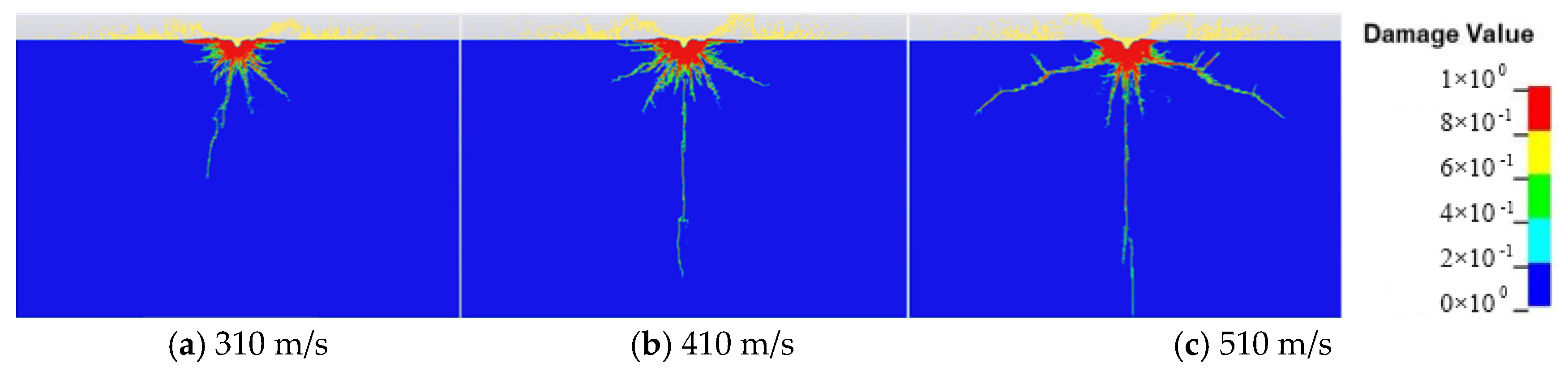
To investigate the effect of the velocity of the waterjet on the propagation of the cracks, different velocities of waterjet are selected (310 m/s, 410 m/s, and 510 m/s) while controlling other parameters as constant (jet diameter of 2 mm and concentration of abrasive of 25%). The velocity of the waterjet (e.g., the velocity of abrasive particles and water) determines the impact energy and thus has a significant influence on the development of the cracks in concrete subjected to the waterjet. It is shown in Figure 8 that the concrete crush zone is enlarged and that the concrete damage degree increases with the velocity of the waterjet. When the velocity of the waterjet is 310 m/s, the impact damage is concentrated near the contacted interface between the waterjet and concrete, with a small degree of damage (Figure 8a). When the velocity of the waterjet is 420 m/s, a large crushing zone forms, the conical cracks transversely extend, and the central crack is formed (Figure 8b). When the velocity of the waterjet reaches 510 m/s, the conical cracks and the central crack further extend and more damage to the concrete occurs. Thus, it is confirmed that a low waterjet velocity cannot effectively fracture the concrete.
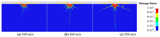
Figure 8.
Effect of the waterjet velocity on the crack.
For the analysis of the effect of the jet diameter on the propagation of the cracks, three groups of jet diameters, 0.76 mm, 1.02 mm, and 2 mm, are considered. Other parameters, such as the velocity of the jet and the concentration of abrasive particles, are kept constant at 410 m/s and 25%, respectively. Considering the same concentration of abrasive particles, the impact kinetic energy is changed when setting different jet diameters. This causes the different concrete cracking effects. Figure 9 shows the influence of the jet diameter on the cracks. For the small jet diameter case (Figure 9a,b), the longitudinal and conical concrete cracks are not fully formed due to the smaller jet diameter carrying a lower mass of water and abrasive particles. With the increase in jet diameter, the longitudinal cracks and transversely developed conical cracks are gradually formed. For a jet diameter of 2 mm, the conical cracks extend more significantly, while the central crack is almost stable (Figure 9c).
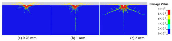
Figure 9.
Effect of jet diameter on the crack.
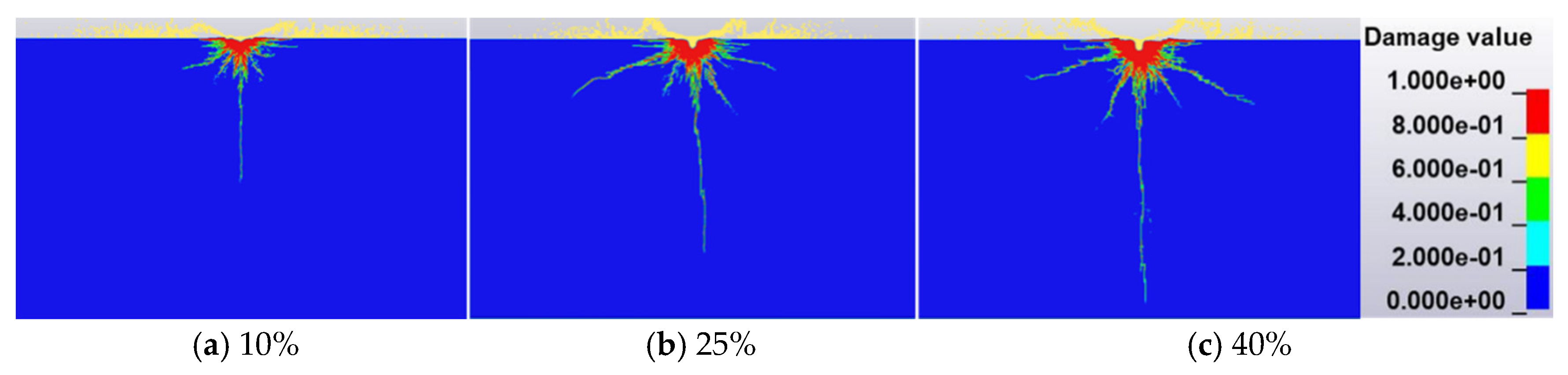
To investigate the effect of the concentration of abrasive particles on the propagation of the cracks, three groups of concentration of abrasive particles (10%, 25%, and 40%) are selected, while other parameters are kept constant (velocity of waterjet of 410 m/s and jet diameter of 1 mm). As shown in Figure 10a, when the concentration of abrasive particles is 10%, a small “crater” appears near the surface of concrete and the main cracks are longitudinal cracks. When the concentration of abrasive particles increases to 25%, the conical cracks are transversely formed, but mainly with an extension of longitudinal cracks. However, there is no significant improvement in cracks propagation when the concentration of abrasive particles reaches 40%. Comparing these three groups of abrasive particle concentrations, it is concluded that the development of longitudinal cracks is more significant than the conical cracks with the increase in abrasive particle concentrations and that the crush zone is in the shape of an “inverted funnel”.
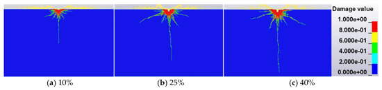
Figure 10.
Effect of concentrate of abrasive particles on the crack.
3.3. Evaluation of the Optimal Combination of Jet Parameters
To evaluate the effects of the jet parameters on concrete damage, waterjet velocity, jet diameter, and abrasive particle concentrations were selected. Based on the damage value Da, the concrete crushing parameter (damage degree χ) is introduced [29] and expressed as follows:
where A1~A10 are the unit areas corresponding to the damage value Da, as is shown in Table 3. Aall is the sum of total unit areas and χ represents the overall damage degree of the waterjet impacting on the concrete.
Table 3.
Damage degrees under different unit areas.
In this study, the term damage degree (χ) refers to a global scalar metric that quantifies the overall extent of damage in the concrete target due to abrasive waterjet impact. It is derived by aggregating local damage values across the simulation domain, weighted by element area, as defined in Equation (9). Unlike a constitutive damage parameter, χ does not directly affect the stress–strain behavior during simulation but instead serves as a post-processed index for comparing overall damage severity across test conditions.
This concept differs from the Kachanov damage variable used in classical continuum damage mechanics (CDM), where a scalar damage variable D ∈ [0, 1] progressively reduces effective stiffness within a constitutive law. Kachanov’s formulation governs material degradation directly in the stress–strain response. In contrast, our definition of χ is observational and cumulative, aimed at evaluating the macroscopic damage outcome based on simulation results rather than altering the material response.
To better understand the effect of different jet parameters on the concrete damage process within a limited number of experiments, an orthogonal test is applied to determine the optimal combination of jet parameters that ensures a high-quality estimation based on set criteria; it is also less sensitive to noise variance parameters. The unit area of the damage at 60 μs is extracted for estimating the damage degree χ and the impact depth h. Taking χ and h as response indices, a three-jet parameter (i.e., velocity of the waterjet, jet diameter, and abrasive particle concentrations) and the three-level orthogonal test is conducted, as shown in Table 4.
Table 4.
Different values of jet parameters in the orthogonal test.
The range analysis is used to determine whether the effect of jet parameters on the concrete crushing is significant and to find the optimal parameter combination. Its expression is shown as follows:
where R is the range index, i is the number of levels, Ki is the total average for the ith level. The larger index R indicates the more significant effect of jet parameters on damage degree χ and impact depth h.
To systematically evaluate the influence of jet parameters on concrete damage, an L9 (33) orthogonal array design is employed. This design enables efficient analysis of the main effects of three independent variables (jet velocity, jet diameter, and abrasive particle concentrations) at three levels, while limiting the number of required simulations to nine. Such a design is widely adopted in parametric studies for its ability to maintain statistical balance and support reliable ANOVA and range analysis with minimal computational overhead. The selected levels (e.g., jet velocity: 310, 410, and 510 m/s) reflect practical ranges observed in field applications, corresponding to pump capacities commonly used in abrasive waterjet cutting for rock and concrete. Similarly, the chosen jet diameters and abrasive concentrations represent standard operational configurations that offer a balance between cutting efficiency and system constraints. This structured approach ensures that the derived conclusions are both statistically robust and relevant to engineering practice.
The orthogonal test results are shown in Table 5, which indicates that damage degree χ is related to both transverse and longitudinal damage. Jet diameter has the largest effect on damage degree χ, followed by abrasive particle concentrations; waterjet velocity has the least effect. In the case of the same abrasive particle concentrations, the increase in jet diameter means higher amounts of abrasive particles and water, more kinetic energy, a larger jet impact range, and more obvious damage in the longitudinal direction. Therefore, the overall damage zone of concrete increases significantly with the jet diameter. However, the largest contribution to impact depth h is the concentration of abrasive particles. The sort results indicate that the effects of the jet parameters on impact depth h are in the following order, jet diameter > velocity of waterjet > concentration of abrasive particles.
Table 5.
Range analysis for χ and h.
The variance analysis, selected to analyze the difference between results caused by changes in influencing parameters and error fluctuations, is expressed as follows:
where m is the number of levels and n is the total number of the orthogonal test. k is the number of the index, Yij is the value of index j at the ith level, Fj is the degree of freedom, Sj is the sum of squared deviations, fE () is the degree of freedom of test error, and fT is the total degree of freedom.
To quantitatively assess the influence of each jet parameter on damage degree (χ) and impact depth (h), the computed F-values from the orthogonal test were evaluated against the corresponding critical values from the F-distribution with degrees of freedom df1 = 2 and df2 = 2. The critical thresholds are F0.10(2,2) = 8.53 for 90% confidence and F0.05(2,2) = 19.00 for 95% confidence. As presented in Table 5, for the response variable χ, the F-values for jet diameter (39.69) and abrasive concentration (13.07) exceed both critical values, indicating their statistically significant contribution at the 95% confidence level. However, the F-value for jet velocity (5.45) falls below these thresholds, suggesting that it has a limited effect on the overall damage degree. In the case of impact depth h, all three factors—jet velocity (20.45), jet diameter (23.84), and abrasive concentration (32.45) surpass the 90% significance threshold, with the latter two also exceeding the 95% threshold. This confirms that while all parameters influence impact depth, jet diameter and abrasive concentration exert the most substantial effects. These results are consistent with the range analysis and reinforce the conclusion that jet diameter and abrasive concentration are the dominant factors governing both concrete damage extent and penetration depth, whereas jet velocity primarily affects impact depth rather than overall damage dispersion.
Given a significance level of 0.1, it can be seen from Table 5 that all Fi are greater than F0.1, with a confidence level of 90% or more, indicating that all three jet parameters (velocity of waterjet, abrasive particle concentration, and jet diameter) are significant to damage degree χ and impact depth h. In addition, it is found that for the effect of jet diameter on damage degree, χ is the most significant and the effect of the abrasive particle concentration on impact depth h is the greatest, which is consistent with the results of the above range analysis.
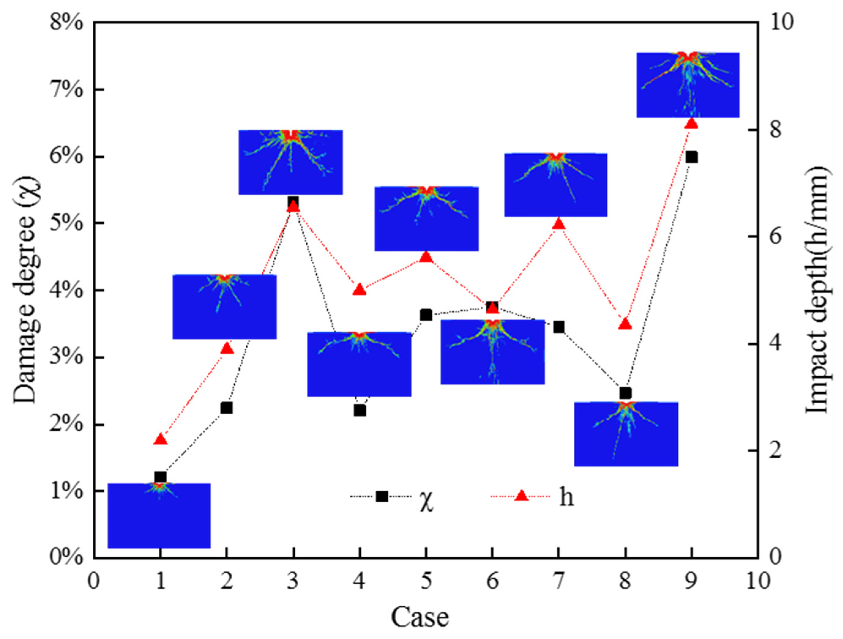
To find the best combination of jet parameters, the different groups of damage degree χ and impact depth h are compared and analyzed. Figure 11 shows the damage curves of damage degree χ and impact depth h under different working conditions. It is illustrated that for different jet diameters, the impact depth h and damage mode of concrete are different. Cases 1, 4 and 8 are featured as the small jet diameter (0.76 mm); their parameter combinations yield a small damage degree χ, a smaller crushing zone, and less sufficient crack propagation. Compared with the impact depth h of case 7, the impact depth h of case 6 is relatively shallow due to the small concentration of abrasive particles and large jet diameter; however, the damage degree χ of case 6 is larger than that of case 7. When the impact depth of the case is shallow, the jet has a large impact on the concrete surface, resulting in a larger range of transverse damage than longitudinal damage. Correspondingly, due to the high concentration of abrasive particles of case 7, the impact depth is significantly larger than that in case 6. Similarly, the concentrations of abrasive particles for cases 3 and 9 is the largest and the impact depth and longitudinal damage penetration are significantly deepened, which indicates the importance of abrasive particle concentrations on the impact depth for concrete.
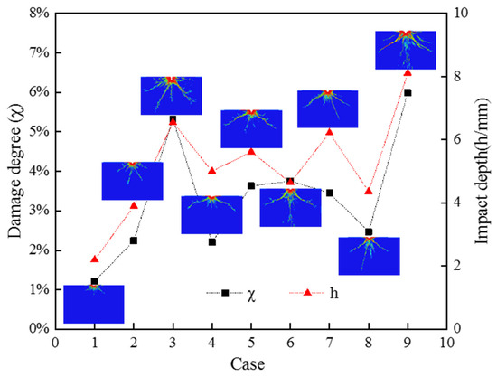
Figure 11.
Damage curves of damage degree χ and impact depth h value under different working conditions.
For the jet parameter combination in case 9, the values of damage degree χ and impact depth h are both at the maximum and the concrete is most severely damaged. Therefore, the optimal parameter combination is the velocity of the waterjet of 510 m/s, the jet diameter of 2 mm, and the concentration of abrasive particles of 25%.
3.4. Parameters Configuration for Tunneling Assisted with Abrasive Waterjet
In geotechnical engineering, TBM assisted with high-pressure waterjet has been used to overcome difficulties when encountering hard rocks or abandoned pile foundations (e.g., reinforced concrete piles). In TBM assisted with abrasive waterjet for breaking rocks [30,31], the rolling cutter and the abrasive waterjet work together. The rock strength is reduced by jet impact, which can increase the rock-breaking efficiency and reduce the load and abrasion of the rolling cutter. In shield tunneling assisted with abrasive waterjet for cutting reinforced concrete piles [32,33], the abrasive waterjet works separately from the shield cutter and the abrasive waterjet impacts the reinforced concrete several times. The main purpose of the abrasive waterjet, in this case, is to truncate the rebar in the reinforced concrete into several sections in advance, which can prevent the long rebar wrapping around the shield cutter and thus reduce jamming accidents.
The key point of TBM assisted with abrasive waterjet for breaking rock is to form the overall damage, not only to cut in the longitudinal direction. The load reduction effect of the shield cutter is insignificant when the cutting depth reaches a certain level [26]. Considering the effect of jet parameters on damage degree χ and impact depth h in the above range and variance analysis, it is possible to use the larger jet diameter to reduce the project cost by reducing the longitudinal damage range to a certain extent while ensuring the transverse damage range. The velocity of the waterjet is controlled by pump pressure, the fast velocity results from the high pumping pressure. Therefore, the configuration of jet parameters for the TBM assisted with abrasive waterjet for breaking rock can follow the concept of higher pump pressure, larger jet diameter, and fewer abrasive particles. Some existing rock-breaking cases show that the rock can be broken without the use of abrasive particles in the waterjet system.
For shield tunneling assisted with abrasive waterjet for cutting reinforced concrete piles, the impact depth of the waterjet on the reinforced concrete must be guaranteed; thus, the concentration of abrasive particles should be increased as much as possible until reaching the optimal concentration of abrasive particles. According to the variance and range analysis, the jet diameter has the lowest influence on impact depth. Meanwhile, shield tunneling with assisted abrasive waterjet for cutting reinforced concrete piles often occurs in sandy soil, clay, sandy cobble stratum, etc. Increasing the use of water in these strata can increase risk during shield tunneling. It is recommended to use a small-diameter mixing tube and a small jet diameter to reduce the water flow under the premise of high pump pressure. Therefore, shield tunneling with abrasive waterjet for cutting reinforced concrete piles can follow the concepts of higher pump pressure, smaller jet diameter, and more abrasive particles.
4. Conclusions
The abrasive waterjet has been identified as a sustainable and green construction practice that can be used in demolition and pile cutting during shield tunneling operation. The factors influencing the operation of abrasive waterjet in such construction practices were investigated in this study. Concrete subjected to abrasive waterjet was simulated, in which the Smoothed Particle Hydrodynamics (SPH)–Finite Element Method (FEM) algorithm was employed to model the abrasive waterjet and the Riedel–Hiermaier–Thoma (RHT) model was used to the model the concrete. First, the damage mechanism of concrete was investigated. Then, the effect of the jet parameters on crack formation was studied. Finally, orthogonal tests were conducted to determine the configuration of the jet parameters for different projects. The main conclusions are as follows:
- (1)
- Concrete subjected to abrasive waterjet can produce conical cracks, longitudinal cracks, circumferential cracks, and central cracks. The crushing zone and deep crater are developed in the early and middle stages of jet impact. Damage in the later stage of impact is dominated by circumferential and central cracks;
- (2)
- The damage of concrete subjected to abrasive waterjet can be divided into a crushing zone, crack formation zone and crack propagation zone. The crushing zone is caused by the shear stress. Plastic strain can cause damage accumulation, which is featured as plastic damage failure. Plastic damage failure occurs in the crack formation zone, followed by brittle damage, in which brittle damage is prominent. Brittle failure occurs in the crack propagation zone due to the large tensile stress;
- (3)
- The jet diameter has the largest effect on damage degree χ, followed by the concentration of abrasive particles. The velocity of the waterjet has the least effect. The concentration of abrasive particles has the largest effect on impact depth h, followed by the velocity of the waterjet. The jet diameter has the least effect;
- (4)
- The configuration of jet parameters in TBM assisted with waterjet for breaking rock follows the concept of higher pump pressure, larger jet diameter, and fewer abrasive particles. Shield tunneling assisted with abrasive waterjet for cutting reinforced concrete piles should follow the concept of higher pump pressure, smaller jet diameter, and more abrasive particles.
When used for demolition, abrasive waterjet technology provides reduced dust, noise, and secondary waste, which aligns with green demolition practice. The usage of the abrasive waterjet before shield tunneling could also decrease the wear of the cutters, thus making construction more sustainable. Therefore, further study of the decreased wear of shield cutters caused by abrasive waterjet could be of significant value.
In the current investigation of the damage behavior of concrete subjected to abrasive waterjet cutting presented in this research, the concrete was modeled based on a simulation using a two-dimensional plane stress assumption, which may simplify the actual heterogeneous and three-dimensional behavior of reinforced concrete under high-velocity impact. The current model used a 2D plane stress assumption, which does not capture out-of-plane stress effects. Material heterogeneity and reinforcement in real concrete are simplified as a homogeneous material in the model. The influence of repeated impact, cumulative fatigue, and varying ambient pressure conditions are not covered in the present study. While this simplification is acceptable for preliminary parametric analysis and mechanism exploration, future studies are encouraged to develop full 3D numerical models that can better capture out-of-plane stress wave propagation, complex crack geometry, and material heterogeneity. Such 3D simulations would offer more comprehensive insights, particularly for structural components with irregular geometries or reinforcement patterns.
Author Contributions
Conceptualization, G.W., X.H. and J.S. methodology, G.W. and X.H.; validation, G.W., C.C. and J.S.; formal analysis, G.W. and X.H.; data curation, C.C.; writing—original draft preparation, G.W., J.S., X.H. and C.C.; writing—review and editing, G.W. and J.S.; visualization, C.C.; supervision, G.W.; funding acquisition, G.W. All authors have read and agreed to the published version of the manuscript.
Funding
This work was supported by Hunan Provincial Natural Science Foundation of China (No. 2024JJ6188), by National Natural Science Foundation of China (NSFC) (Grant No. 52408364) and by Open Project of Xiangjiang Laboratory (No. 22XJ01003, 23XJ01007, 24XJ01003).
Data Availability Statement
The raw data supporting the conclusions of this article will be made available by the authors on request.
Conflicts of Interest
The funders had no role in the design of the study; in the collection, analyses, or interpretation of data; in the writing of the manuscript; or in the decision to publish the results. The authors declare that they have no known competing financial interest or personal relationships that could have appeared to influence the work reported in this paper.
References
- Al-Kheetan, M.J.; Al-Tarawneh, M.; Ghaffar, S.H.; Chougan, M.; Jweihan, Y.S.; Rahman, M.M. Resistance of Hydrophobic Concrete with Different Moisture Contents to Advanced Freeze–Thaw Cycles. Struct. Concr. 2021, 22, E1050–E1061. [Google Scholar] [CrossRef]
- Berthoz, N.; Branque, D.; Michalski, A.; Mohamad, W.; Bourgeois, E.; Le Kouby, A.; Szymkiewicz, F.; Rallu, A. Impact of Tunnelling on Piles in Parisian Subsoil: Dataset of in-Situ Measurements in the Ground and on Three Instrumented Piles. Data Br. 2023, 47, 108971. [Google Scholar] [CrossRef]
- Liu, J.; Zhu, Y.; Xue, Y.; Sun, H. Fragmentation Pattern and Removal Mechanism of Concrete Subjected to Abrasive Water Jet Impact. Adv. Mater. Sci. Eng. 2021, 2021, 6618386. [Google Scholar] [CrossRef]
- Momber, A.W.; Mohan, R.S.; Kovacevic, R. Fracture Range Detection in Hydro-Abrasive Erosion of Concrete. Wear 2002, 253, 1156–1164. [Google Scholar] [CrossRef]
- Guha, A.; Barron, R.M.; Balachandar, R. An Experimental and Numerical Study of Water Jet Cleaning Process. J. Mater. Process. Technol. 2011, 211, 610–618. [Google Scholar] [CrossRef]
- Liu, X.; Tang, P.; Geng, Q.; Wang, X. Effect of Abrasive Concentration on Impact Performance of Abrasive Water Jet Crushing Concrete. Shock Vib. 2019, 2019, 3285150. [Google Scholar] [CrossRef]
- Li, L.; Wang, F.; Li, T.; Dai, X.; Xing, X.; Yang, X. The Effects of Inclined Particle Water Jet on Rock Failure Mechanism: Experimental and Numerical Study. J. Pet. Sci. Eng. 2020, 185, 106639. [Google Scholar] [CrossRef]
- Jiang, H.; Liu, Z.; Gao, K. Numerical Simulation on Rock Fragmentation by Discontinuous Water-Jet Using Coupled SPH/FEA Method. Powder Technol. 2017, 312, 248–259. [Google Scholar] [CrossRef]
- Xue, Y.; Si, H.; Chen, G. The Fragmentation Mechanism of Coal Impacted by Water Jets and Abrasive Jets. Powder Technol. 2020, 361, 849–859. [Google Scholar] [CrossRef]
- Adsul, S.; Srinivasu, D.S. Modelling the Cross-Sectional Profile of the Kerf Generated in Overlapped Pass Erosion in Abrasive Waterjet Milling of Al6061-T6 Alloy. J. Manuf. Process. 2023, 102, 297–318. [Google Scholar] [CrossRef]
- Blais, P.; Lotfi, T.; Zitoune, R. Damage Created by Abrasive Waterjet and Conventional Drilling in Open-Hole and Assembled 3D Interlock Woven Carbon Fiber-Reinforced Plastic Composites Examined by Fatigue Testing and Linear Regression Analysis. Eng. Fail. Anal. 2025, 168, 109099. [Google Scholar] [CrossRef]
- Mahdevari, S.; Sayehvand, H.; Bakhtiari Haftlang, P. Numerical Modeling of Abrasive Waterjet to Optimize Rock Cutting Parameters. Sci. Rep. 2025, 15, 15212. [Google Scholar] [CrossRef] [PubMed]
- Chen, X.; Xu, G.; Xu, X.; Jiang, H.; Tian, Z.; Ma, T. Multicenter Hierarchical Federated Learning With Fault-Tolerance Mechanisms for Resilient Edge Computing Networks. IEEE Trans. Neural Netw. Learn. Syst. 2024, 36, 47–61. [Google Scholar] [CrossRef] [PubMed]
- Xu, X.H.; Du, Z.J.; Chen, X.H.; Cai, C.G. Confidence Consensus-Based Model for Large-Scale Group Decision Making: A Novel Approach to Managing Non-Cooperative Behaviors. Inf. Sci. 2019, 477, 410–427. [Google Scholar] [CrossRef]
- Li, X.; Chen, X. Value Determination Method Based on Multiple Reference Points under a Trapezoidal Intuitionistic Fuzzy Environment. Appl. Soft Comput. J. 2018, 63, 39–49. [Google Scholar] [CrossRef]
- Liu, D.; Liu, Y.; Chen, X. The New Similarity Measure and Distance Measure of a Hesitant Fuzzy Linguistic Term Set Based on a Linguistic Scale Function. Symmetry 2018, 10, 367. [Google Scholar] [CrossRef]
- Zhou, X.; Wu, J.; Liang, W.; Wang, K.I.K.; Yan, Z.; Yang, L.T.; Jin, Q. Reconstructed Graph Neural Network With Knowledge Distillation for Lightweight Anomaly Detection. IEEE Trans. Neural Netw. Learn. Syst. 2024, 35, 11817–11828. [Google Scholar] [CrossRef]
- Wang, G.; Singh, J.; Tan, J.; Li, G. Use of Predictive Model for Identification of Overall Wear State of TBM Cutterhead Based on Tunneling Parameters. Expert Syst. Appl. 2025, 268, 126316. [Google Scholar] [CrossRef]
- Huang, Y.; Dai, Z.; Zhang, W.; Chen, Z. Visual Simulation of Landslide Fluidized Movement Based on Smoothed Particle Hydrodynamics. Nat. Hazards 2011, 59, 1225–1238. [Google Scholar] [CrossRef]
- Liang, H.; He, S.; Lei, X.; Bi, Y.; Liu, W.; Ouyang, C. Dynamic Process Simulation of Construction Solid Waste (CSW) Landfill Landslide Based on SPH Considering Dilatancy Effects. Bull. Eng. Geol. Environ. 2019, 78, 763–777. [Google Scholar] [CrossRef]
- Cremonesi, M.; Franci, A.; Idelsohn, S.; Oñate, E. A State of the Art Review of the Particle Finite Element Method (PFEM). Arch. Comput. Methods Eng. 2020, 27, 1709–1735. [Google Scholar] [CrossRef]
- Ma, L.; Bao, R.H.; Guo, Y.M. Waterjet Penetration Simulation by Hybrid Code of SPH and FEA. Int. J. Impact Eng. 2008, 35, 1035–1042. [Google Scholar] [CrossRef]
- Riedel, W.; Thoma, K.; Hiermaier, S.; Schmolinske, E. Penetration of Reinforced Concrete by BETA-B-500 Numerical Analysis Using a New Macroscopic Concrete Model for Hydrocodes. In Proceedings of the 9th International Symposium on the Effects of Munitions with Structures, Berlin, Germany, 3–4 May 1999; pp. 315–322. [Google Scholar]
- Li, Z.; Liu, Z. Review of Concrete Dynamic Constitutive Mode. J. Tianjin Univ. 2015, 10, 853–863. [Google Scholar]
- Anwar, S.; Axinte, D.A.; Becker, A.A. Finite Element Modelling of Abrasive Waterjet Milled Footprints. J. Mater. Process. Technol. 2013, 213, 180–193. [Google Scholar] [CrossRef]
- Zhang, J.; Li, Y.; Zhang, Y.; Yang, F.; Liang, C.; Tan, S. Using a High-Pressure Water Jet-Assisted Tunnel Boring Machine to Break Rock. Adv. Mech. Eng. 2020, 12, 1–16. [Google Scholar] [CrossRef]
- LS-DYNA Keyword User’s Manual Volume I; Livermore Software Technology Corporation (LSTC): California, CA, USA, 2007.
- Liu, J.; Du, S.; Xue, Y. Study on the Breaking Process and Damage Characteristics of Abrasive Water Jet Impacting Concrete Based on Acoustic Emission. Constr. Build. Mater. 2020, 262, 120085. [Google Scholar] [CrossRef]
- Liu, J.; Zhu, Y.; Du, S. Failure Mechanism and Effect of Nozzle Parameters on Abrasive Water Jet Rock Breaking. Shock Vib. 2021, 2021, 6621255. [Google Scholar] [CrossRef]
- Cheng, J.L.; Jiang, Z.H.; Han, W.F.; Li, M.L.; Wang, Y.X. Breakage Mechanism of Hard-Rock Penetration by TBM Disc Cutter after High Pressure Water Jet Precutting. Eng. Fract. Mech. 2020, 240, 107320. [Google Scholar] [CrossRef]
- Ciccu, R.; Grosso, B. Improvement of Disc Cutter Performance by Water Jet Assistance. Rock Mech. Rock Eng. 2014, 47, 733–744. [Google Scholar] [CrossRef]
- Kohashi, S.; Takasaki, H.; Matsui, K.; Ohashi, A.; Matsuike, T.; Sawa, Y. Application of Water Jet Cutting to Treatment for Obstructive Piles. In Proceedings of the 13th International Symposium on Automation and Robotics in Construction, Tokyo, Japan, 11–13 June 1996; pp. 315–322. [Google Scholar] [CrossRef]
- Wang, G.; Qiao, S.; Wang, G.; Jiang, H.; Singh, J. Cutting Depth of Pile Materials Subjected to the Abrasive Waterjet and Its Prediction Model. Tunn. Undergr. Space Technol. 2022, 124, 104473. [Google Scholar] [CrossRef]


Disclaimer/Publisher’s Note: The statements, opinions and data contained in all publications are solely those of the individual author(s) and contributor(s) and not of MDPI and/or the editor(s). MDPI and/or the editor(s) disclaim responsibility for any injury to people or property resulting from any ideas, methods, instructions or products referred to in the content. |
© 2025 by the authors. Licensee MDPI, Basel, Switzerland. This article is an open access article distributed under the terms and conditions of the Creative Commons Attribution (CC BY) license (https://creativecommons.org/licenses/by/4.0/).