Abstract
The present study investigates the influence of the configurations of anchor bolts and stiffeners on the monotonic response under moment conditions in the major axis and compression force of partial-strength exposed column base plate connections in order to ameliorate their response, limiting the number of welded details. Parametric finite element simulations were performed based on models calibrated against experimental results available from the recent literature. The results show the efficiency of the investigated configurations, namely, (i) the presence of rib stiffener results in high stiffness and strength with a reduction in ductility; (ii) the linear pattern of anchor bolts (e.g., rectangular distribution) is characterized by the limited contribution of the outer anchor bolts to the overall resistance of the connection; (iii) the trapezoidal pattern of the anchor bolts exhibit a better mechanical performance as well as their efficiency; and (iv) the increase in compression force influences the mechanical response of the base connection with an increase in both resistance and rigidity until the column is stable against the moment–axial force interaction.
1. Introduction
Column base plate connections, linking the column to the foundation, play a paramount part in the structural behavior of the steel moment-resisting frames. Assumed categories for column base plates are pinned or fixed. However, their actual behavior is far from the ideal pinned or fixed assumption [1].
Embedded into the concrete of the foundations, exposed column base plate connections are commonly and alternatively used in steel structures. Embedded column base plate connections are commonly used when significant bending moments are dominant or mid-rise to high-rise (>4-story) buildings are needed. The bearing between the column flange and the foundation provides the resistance mechanism. However, the connections can be substituted with exposed ones in low- to mid-rise buildings [2]. The behavior of the exposed column base connection is inherently linked to the behavior of the column, anchor bolts, base plate, foundation, and grout. Due to its significance and sensitivity to various components, the exposed column base plate connection has been the subject of numerous studies.
Thambiratnam and Paramasivam [3] experimentally studied 12 base plate connections with a distinct eccentricity and base plate thickness under axial forces or bending moments. These connections experienced grout failure when loaded in low eccentricity conditions but faced anchor bolts and/or the yielding of the base plate in bending in high eccentricity conditions. Fahmy et al. [4] observed the brittle failure in the welded zone of the base plate close to the column flange because of the triaxial strain. Furthermore, the inner anchor bolts (near the column flange region) experienced more axial force than the outer ones (far from the column region). Seven base plate connections, designed according to AISC Steel Design Guide Series One [5], were tested by Gomez et al. [6] under monotonic and cyclic loads to check and ameliorate the design procedure. The numerical study of Kanvinde et al. [7] highlighted that in thick base plate connections, the stress is distributed at the flange edge despite the assumption of uniformity between the grout and the base plate.
The reliability of the connections designed according to Eurocode [8] was analyzed by Latour and Rizzano [9], highlighting the unsafe design of unstiffened connections. Latour and Rizzano [10] proposed a theoretical formula for the rotation of the exposed base plate connections, compatible with the component method, which was verified with experimental results [11]. Shaheen et al. [12] underlined the significant role of the grout on the base plate connection because of its ability to resist the shear forces and facilitate the erection process. Díaz et al. [13] suggested a design method for unstiffened and stiffened column base plate connections after assessing their failure mechanism by considering several parameters, including the anchor bolt location, base plate thickness, and anchor bolt tensile strength.
Kabir et al. [14] predicted the failure modes of base plate connections using machine learning, trained on a dataset of 189 samples. Pan et al. [15] tested six column base plate connections fastened to the foundation with four internal anchor bolts under cyclic major and minor axis bending. The verified numerical model data were utilized to calibrate a regression model to predict the response curve of the connection under the minor axis. Song et al. [16] evaluated the reliability of the column base plate connections designed according to AISC Steel Design Guide Series One [5] by utilizing the Monte Carlo Simulation. Mehdi et al. [17] monitored the base plate connections’ local and global behavior, including the prying force, stiffener effect, and anchor bolt bending. Torres-Rodas et al. [18] applied extended anchor bolts in the column base plate connections to ameliorate the ductility of the connection by concentrating the plasticity in the anchor bolts and making the remaining components elastic.
Al-Sharmootee et al. [19] numerically studied four distinct stiffeners’ effects on the exposed column base plate connection under a cyclic load. The results indicated that the connection was strengthened and stiffened compared to the column; moreover, the stiffeners caused the anchor bolts to behave as fuse elements due to the base plate reinforcement. Shaheen et al. [20] improved the rotation capacity without any decrease in the initial stiffness or strength of column base plate connections by adding steel sleeves among the anchor bolts and base plates. Aichouche et al. [21] highlighted the possibility of a local bending moment beside the axial force in the anchor bolts, which can be decreased by adding stiffeners; however, adding stiffeners may generate biaxial bending on them. Nawar et al. [22] experimentally and numerically studied the hinged column base plate connections under axial tension and bending moment conditions with the base plate thickness and anchor bolts’ diameters as variables. The results highlighted the considerable effect of the axial tensile load on the connection stiffness reduction, in addition to a significant gap generation between the base plate and the base beam.
Several approaches can be applied to improve the connection behavior, including modifying the bolt pattern. As pioneers, Kiamanesh et al. [23] suggested a circular bolt pattern instead of the rectangular one in the extended column base plate connections. This method reduced the pinching behavior in the hysteresis curve and resulted in a uniform bolt force. Morrison et al. [24] enhanced the performance of eight bolt end-plate connections by utilizing an octagonal bolt pattern under a cyclic load, reducing the pinching effect. El Kalash and Hantouche [25] studied experimentally and numerically studied the circular bolt pattern effect on the T-stub component, representing the end-plate connection under a monotonic and cyclic load. They highlighted that despite the lower fabrication cost for the circular pattern compared with the rectangular one, the circular one leads to a thicker end-plate. Khani et al. [26] improved the tied-to-rigid-base T-stub component behavior by utilizing a trapezoidal bolt pattern under a monotonic load, causing considerable ductility and bolt efficiency.
Due to the importance of column base plate connections in steel structures, a large number of studies have been carried out, ranging from their reliability and design procedure to their behavioral improvement. Many studies have been conducted to enhance the connection behavior by adding stiffeners or modifying anchor bolts (see Table 1). However, because of the need for welding, adding a stiffener causes a stress concentration in the welded regions in addition to an increase in the constructional costs. To the best of the authors’ knowledge, as well as based on the discussed review of the state of the art, there is a lack of studies aiming at investigating the possibility of ameliorating the response of base plate connections solely focusing on the pattern of anchor bolts in order to limit the constructional costs. This observation motivated the study presented in this paper, which mainly focuses on understanding whether the connection behavior can be ameliorated by simply modifying the layout of the anchor bolts without negatively affecting the economy and safety. Thus, in the present study, exposed column base plate connections with distinct configurations have been studied numerically under a monotonic load to improve the connection performance by achieving an optimized connection pattern. To this end, Section 2 contains the numerical modeling process. Section 3 contains discussions of the obtained results. Finally, this study is concluded in Section 4.

Table 1.
Summary of comparing studies in the literature with the present study.
2. Materials and Methods
Among distinct classifications of column base plate connections, partial-strength connections are more common in the industry due to being economical, practical, and easily fabricated compared to full-strength ones. Since the present study focuses on partial-strength connections, the benchmark test of Gomez et al. [6] was utilized to validate the adopted finite element model. The numerical investigation was performed using ABAQUS 2022 software to monitor the column base plate connections’ local and global performance under distinct configurations.
Once the model was validated, the structural response of different configurations, as well as the influence of the axial force of the column, were investigated by monitoring the moment vs. column drift, anchor bolt behavior, and stress distribution on the components.
2.1. Verified Model
Gomez et al. [6] tested a column base plate connection (i.e., Test #1) with the dimensional and material properties reported in Table 2 and Table 3, respectively, under monotonic loading with no axial load. In Table 2, Lp, Bp, ex, ez, Pfi, gi, and tp indicate the base plate length and width, anchor bolt distance from the edge of the base plate parallel to the column flange, anchor bolt distance from the edge of the base plate along the column web direction, anchor bolt distance from the column flange along the column web direction, gauge distance between the anchor bolt parallel to the column flange, and base plate thickness, respectively. Material properties, including the Young modulus of elasticity E, yield strength fy, ultimate strength fu, ultimate strain εu, and Poisson ratio ν for the column, base plate, and anchor bolts, are listed in Table 2.
Table 2.
Dimensional properties of Test #1 (data are extracted from Gomez et al. [6]).
Table 3.
Material properties of Test #1 (data are extracted from Gomez et al. [6]).
An A992 Grade 50 W8×48 column with a height of 2350 mm was welded to the middle of the base plate. Grade 105 ksi anchor rods with a diameter of 19.05 mm were applied to fasten the connection. A grout with a thickness of 50.8 mm and compressive strength of 51.08 MPa was poured between the base plate and pedestal with a compressive strength of 27.33 MPa.
The stress–strain curve of the material constituting the base plate was simulated through multilinear curves, while a bilinear curve was used to model the column and anchor bolts. The material properties of the grout, pedestal, and foundation were simulated by means of the stress–strain curve given by EN 1992-1-1 [27]. Furthermore, the Concrete Damage Plasticity (CDP) model is used to simulate the failure of concrete and grout. The relevant parameters of CDP (i.e., the eccentricity of the plastic potential surface ε, the dilation angle ψ, the ratio of the second stress invariant on the tensile meridian to compressive meridian at initial yield Kc, the ratio of initial biaxial compressive yield stress to initial uniaxial compressive yield stress fb0/fc0, and the viscosity parameter) are summarized in Table 4.
Table 4.
Concrete Damage Plasticity parameters (data are extracted from reference [28]).
2.2. Modeling of the Investigated Connections
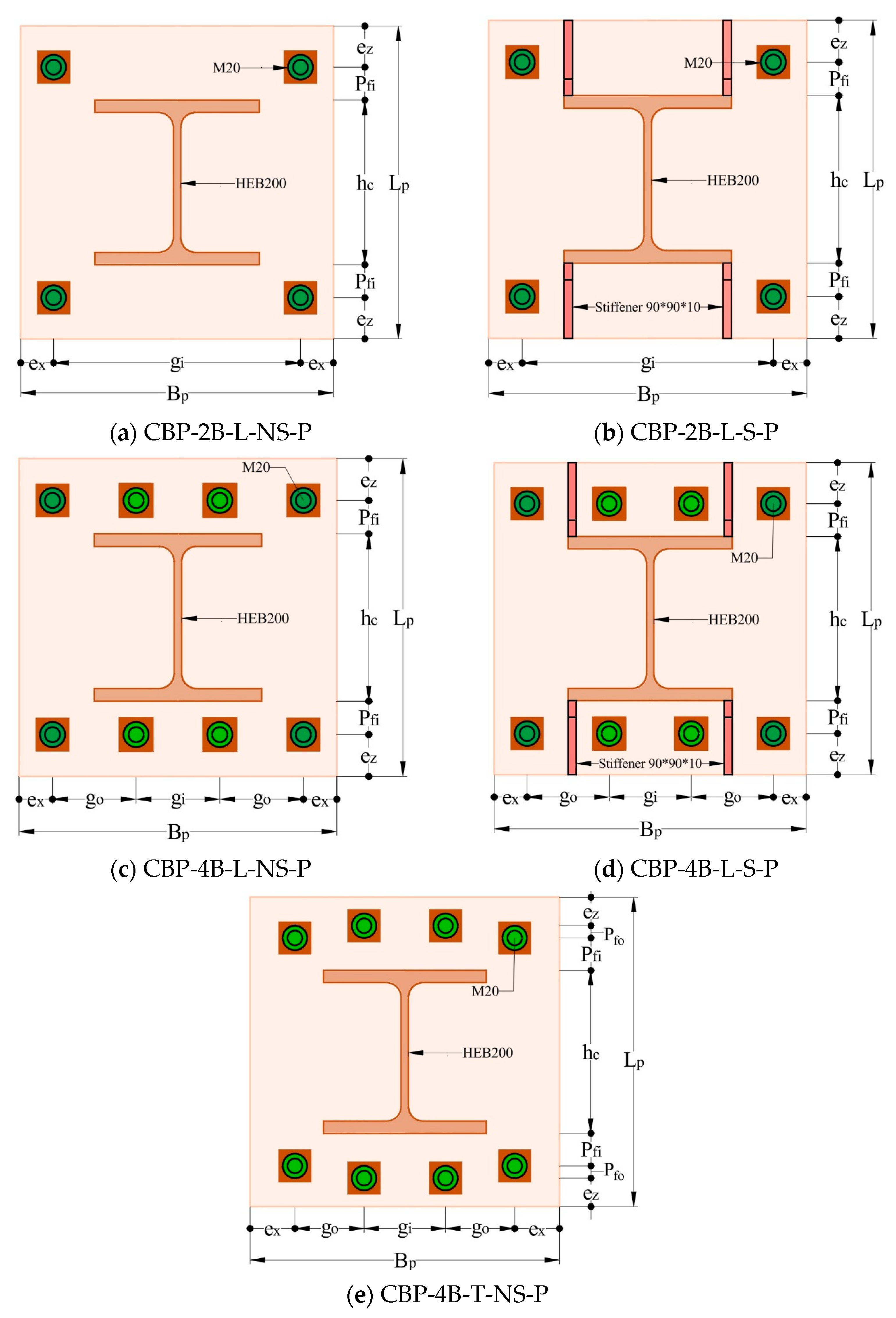
To see the effects of distinct configurations on the local and global performance of the column base plate connection, base plates with various patterns were investigated (i.e., added stiffener or extra anchor bolts as shown in Figure 1). The connections were univocally identified through a labeling code, in which CBP stands for the column base plate; 2B and 4B illustrate 2 and 4 anchor bolts, respectively; L and T stand for the linear and trapezoidal anchor bolt pattern; NS and S indicate the non-existence and existence of a stiffener; and finally, P represents the pretensioned case for anchor bolts. All the models had the same material properties, as mentioned in Section 2.1. The dimensional values of the models are reported in Table 5. The symbols Bp, Lp, tp, Pfi, ex, ez, gi, go, and pfo correspond to the base plate width, length, and thickness, the nearest anchor bolt distance from the column flange in the z-direction, the anchor bolt distance from the edge of the base plate in the x-direction, the anchor bolt distance from the edge of the base plate in the z-direction, the inner gauge distance between the anchor bolt in the x-direction, the outer gauge distance between the anchor bolt in the x-direction, and the distance between the anchor bolts in the z-direction, respectively. It must be highlighted that the selected values are similar to those of Test #1 performed by Gomez et al. [6], but in a practical way with the metric system. Columns are supposed to be HEB200 with a length of 2350 mm.
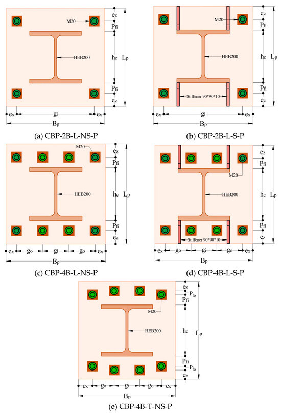
Figure 1.
Schematic of distinct column base plate configurations.
Table 5.
Dimensional properties of the base plates with distinct configurations.
A diameter of 20 mm was assumed for the smooth part of the anchor bolts, while the threaded segments were simulated considering the equivalent diameter of the corresponding reduced area. The grout was assumed to be 50 mm thick and 1.1 times the base plate size. Moreover, the foundation had 1.2 times the dimension of the base plate. Triangular stiffeners with a length, height, and thickness of 90, 90, and 10 mm, respectively, were applied.
2.3. Boundary Conditions and Loadings
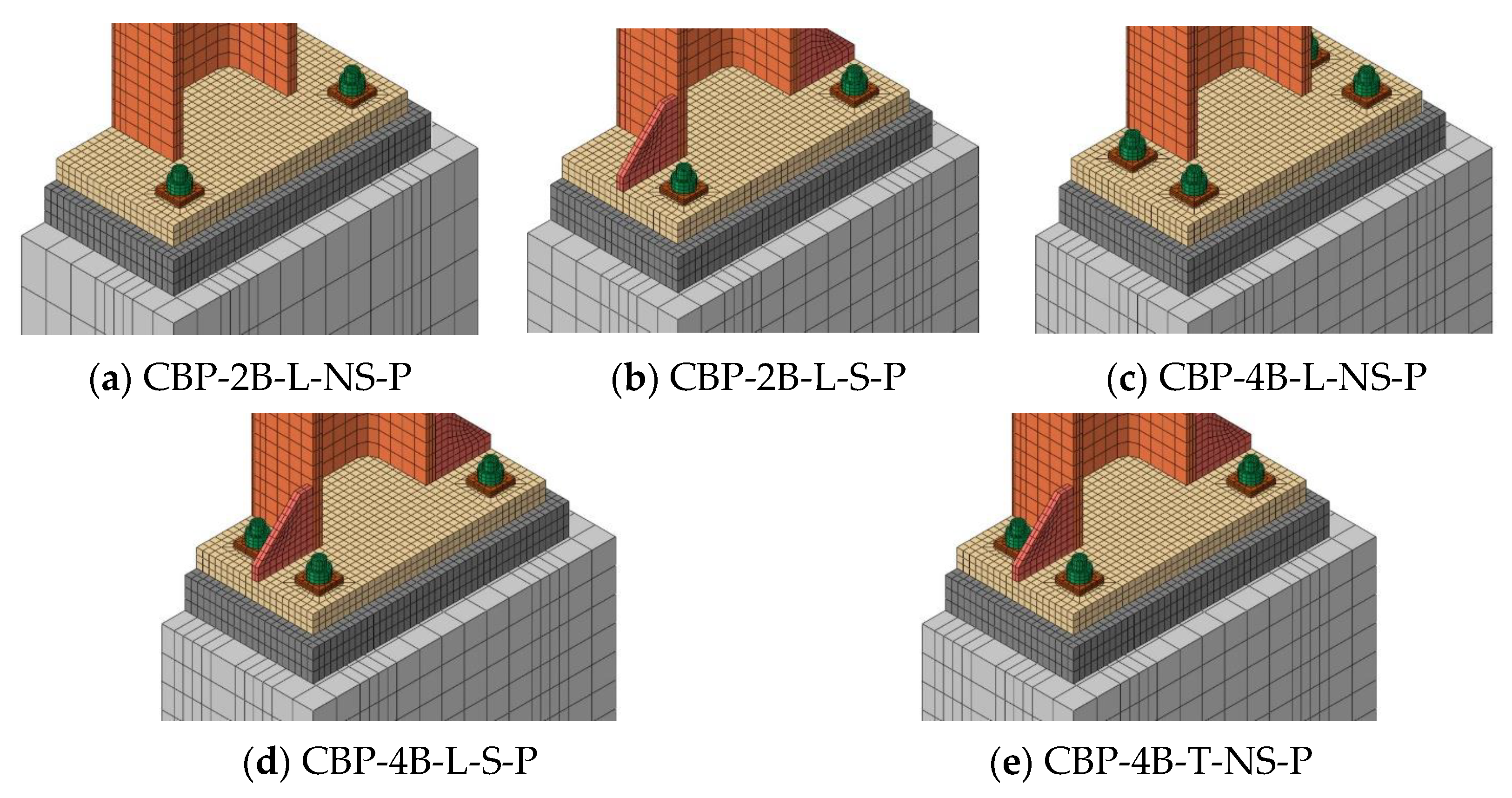
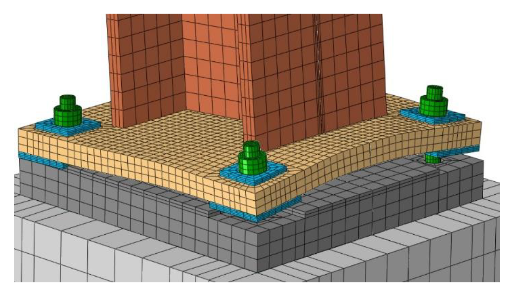
After generating the parts and defining the material properties, the model was assembled, as shown in Figure 2. Only half of each model was modeled thanks to the symmetry in the Y-Z plane. The base of the foundation was considered to be fixed, and symmetry boundary conditions were applied. Models were alternatively studied without and with the column axial force. Without the column axial force, only a nodal displacement was applied at the top of the column in the z-direction to apply bending on the connection. However, in the case of the column axial force, in addition to the nodal displacement in the z-direction, three types of column axial force ratios ρ (ρ = Ned/Npc in which Ned is the column’s axial demand and Npc represents its axial plastic resistance), with values of 0.1, 0.2, and 0.3, were applied to monitor their effect on the connection behavior. The column axial force was supposed to be vertical; thus, to be consistent with the actual condition of a building, nodal rotation was not followed. Also, the anchor bolts were supposed to be pretensioned with values of 181 kN. The pretensioning of the anchor bolts was simulated by the bolt load method in ABAQUS by considering the apply force method in the pretensioning step and applying the fixed at current length option in the following steps. In addition, the geometric nonlinearity was applied to consider the second-order effects (P-Δ). For the analysis procedure, dynamic implicit modeling was applied by considering the quasi-static condition to eliminate the inertial effects and the dynamic nature of the solver. The absence of dynamic effects was verified by checking the ratio of kinematic energy to internal energy, which was almost zero. As shown in Figure 2, the same mesh size (mesh sensitivity analysis is reported in Section 3.1) was applied for all the models with the mesh type of C3D8R.
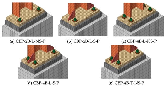
Figure 2.
Assembly of the base plate connection models with distinct configurations.
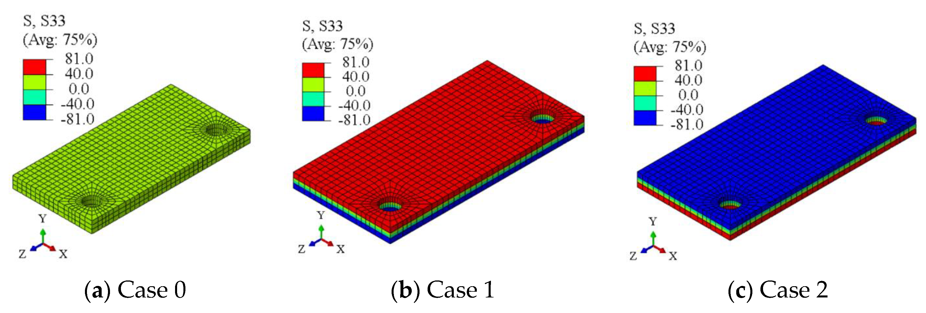
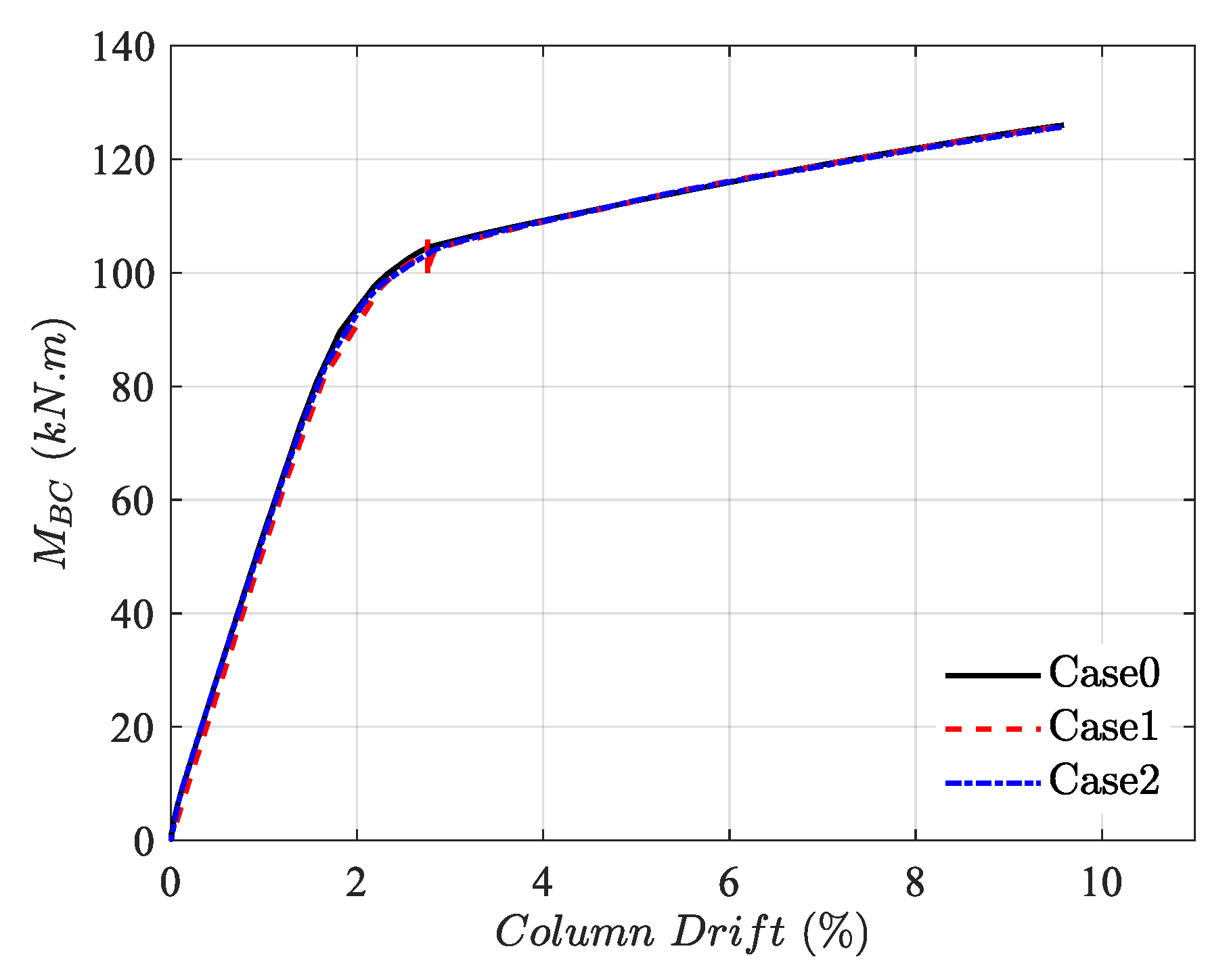
Since the aim of this study was mainly to investigate the initial rigidity and the ultimate resistance of the examined connections once the plastic mechanism is fully developed, residual stresses were not modeled in the parametric study. In fact, it is well known that residual stresses mostly affect the transition from the elastic to the plastic range of the response rather than the initial and final stages of the mechanical response. In addition, residual stresses are also highly sensitive to the manufacturing sequence (welding procedure, assembly of the components, and initial self-stresses of the hot-rolled elements, i.e., both plates and members). However, a preliminary study was carried out to verify their effects on the global response of the connection. Therefore, some models were analyzed by imposing bending residual stresses (equal to 0.30 fy) through the thickness of the base plate; Figure 3 shows the modeled base plate without residual stresses (see case 0 in Figure 3a) and with residual stresses (see case 1 in Figure 3b for hogging deformation of the plate, and case 2 in Figure 3c for sagging deformation of the base plate). Figure 4 shows the comparison of the overall response curves, where negligible differences can be trivially recognized.
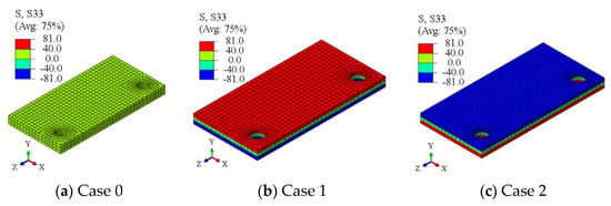
Figure 3.
Modeled residual stress value in the base plate.
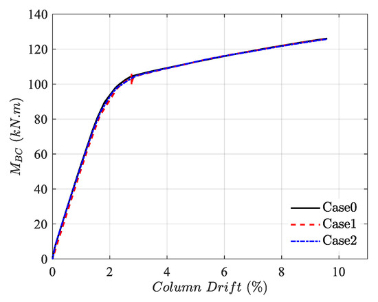
Figure 4.
Effect of residual stresses into the base plate on the moment–column drift curve.
2.4. Contacts and Interactions
Interactions such as surface-to-surface and tie contact interactions existed between the parts, as summarized in Table 6. The tangential behavior with the penalty formulation and normal behavior with the “Hard” contact type were considered in the surface-to-surface interaction. The contact coefficients were assumed to be 0.3 between steel and steel and 0.1 between steel and concrete.
Table 6.
Contact Information.
3. Results
3.1. Verified Model
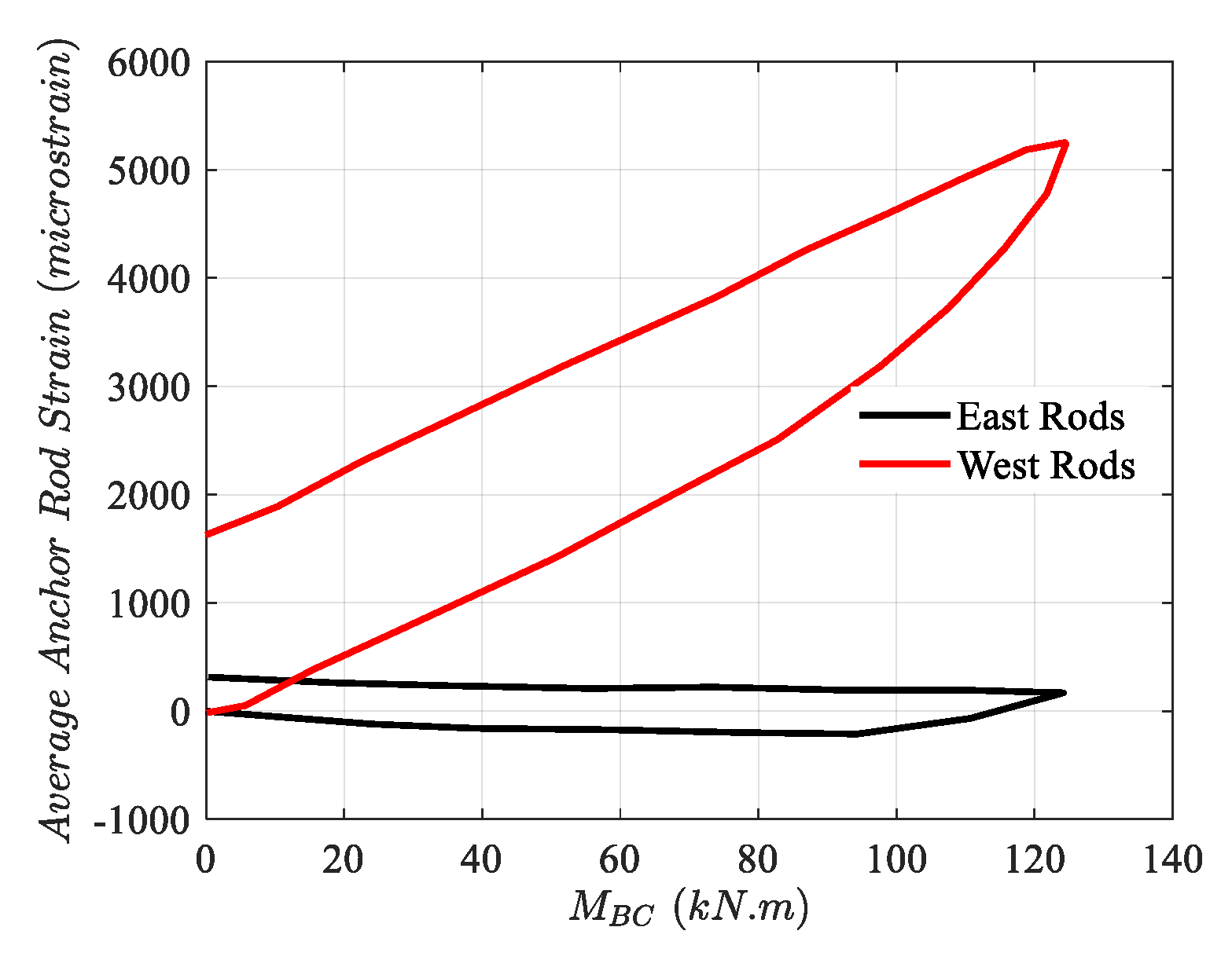
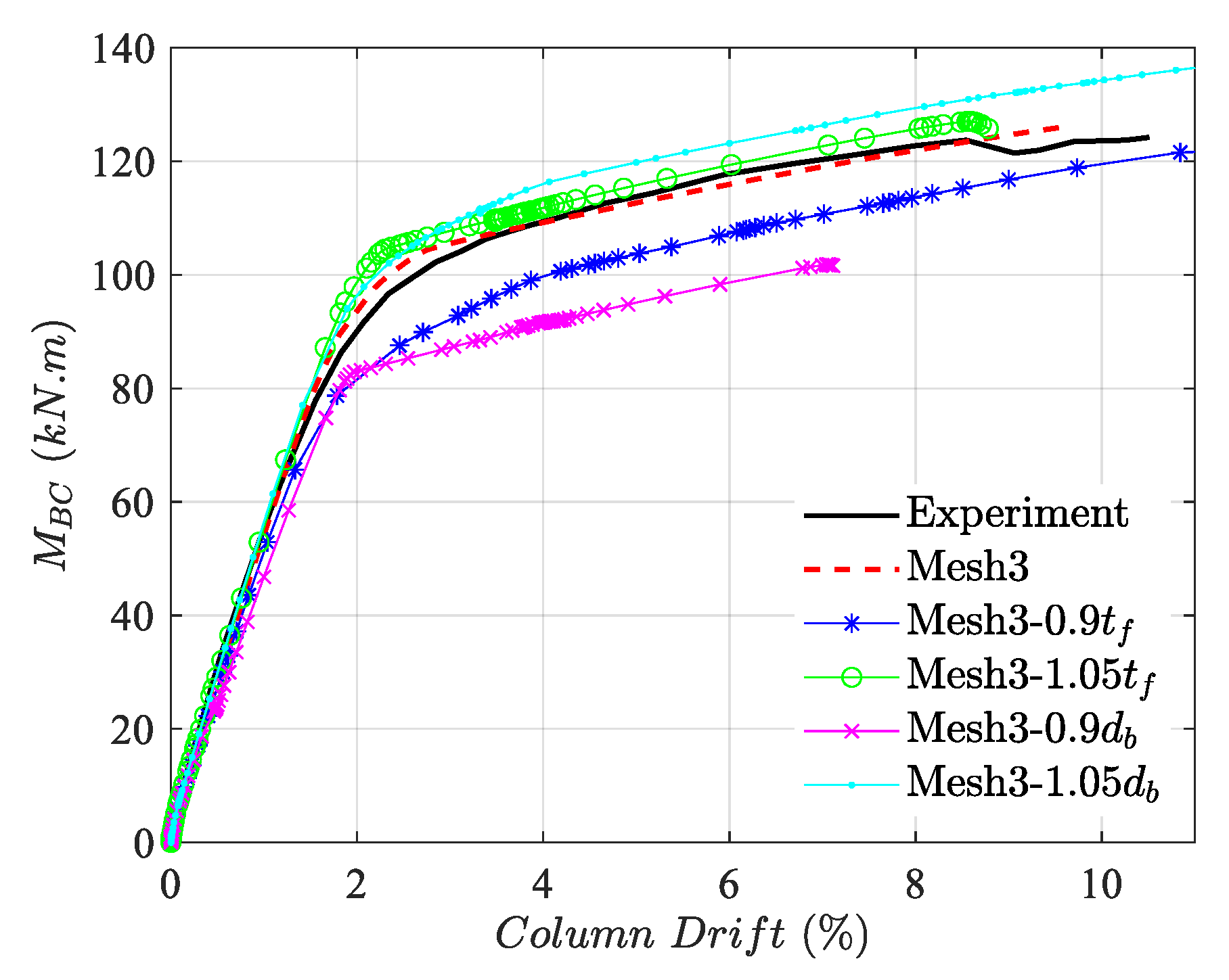
Due to the model’s complexity, local and global verification are mandatory. From a global perspective, the experimental base moment MBC vs. column drift of Test #1 (experimented by Gomez et al. [6]) is compared with four distinct mesh sizes in Figure 5a. The data in Figure 5b show the increasing number of elements from Mesh 1 to Mesh 4 in base plate, anchor bolt, column, and grout (see more data in Table 7); therefore, since after increasing the element number beyond Mesh 3, less of a change was observed in the connection behavior, Mesh 3 was utilized for the remaining models. The results indicate the acceptable performance of Mesh 3 by considering both accuracy and time efficiency. From the local viewpoint, the permanently deformed shape of the base plate under experimental and numerical investigation can be seen in Figure 6, highlighting the base plate yielding on the tension side. Also, Figure 7 indicates the vertical displacement of the base. Moreover, the anchor bolt force Fb vs. the base moment MBC is compared in Figure 8. The initial anchor bolt force in the experiment and numerical model is not the same, which can be attributed to the pretensioning load. It is worth mentioning that despite the absence of an anchor bolt force in the initial stage of the experiment, the strain shown in Figure 9 highlights the existence of marginal pretensioning, which is compatible with torquing an additional one-eighth turn of anchor bolts, as shown by Gomez et al. [6]. Therefore, to better capture the information in the initial stage, a marginal amount of pretensioning compatible with the experiment was considered in the numerical model. Since the model is limited to one experimental verification, to strengthen the credibility of the results, parametric sensitivity studies of the model based on the variation in the main components (base plate thickness and anchor bolt diameter) are shown in Figure 10. Clarifying the labels in the legend, 0.9 tf, 1.05 tf, 0.9 db, and 1.05 db represent the base plate thickness reduction and increase to 0.9 and 1.05 of the initial size, and the decrease and increase in anchor bolt diameter to 0.9 and 1.05 of the initial size, respectively. The results indicate the same trend of the moment–An increase in the thickness and diameter shifts the curve over the base model, but their reduction places the curves under the base case. In all considered cases, bolt failure was the dominant failure mode. According to the global and local comparison of the numerical model with the data in the literature [6,29], the numerical model indicates acceptable accuracy for conducting further studies.
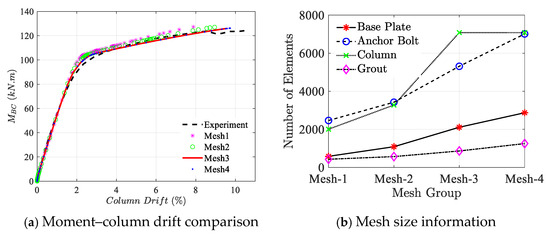
Figure 5.
Comparing the base moment vs. column drift of Test #1 with distinct mesh sizes of the numerical model.
Table 7.
Element size information of the main components.
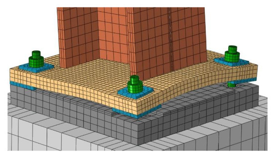
Figure 6.
Permanently deformed shape of Test #1.

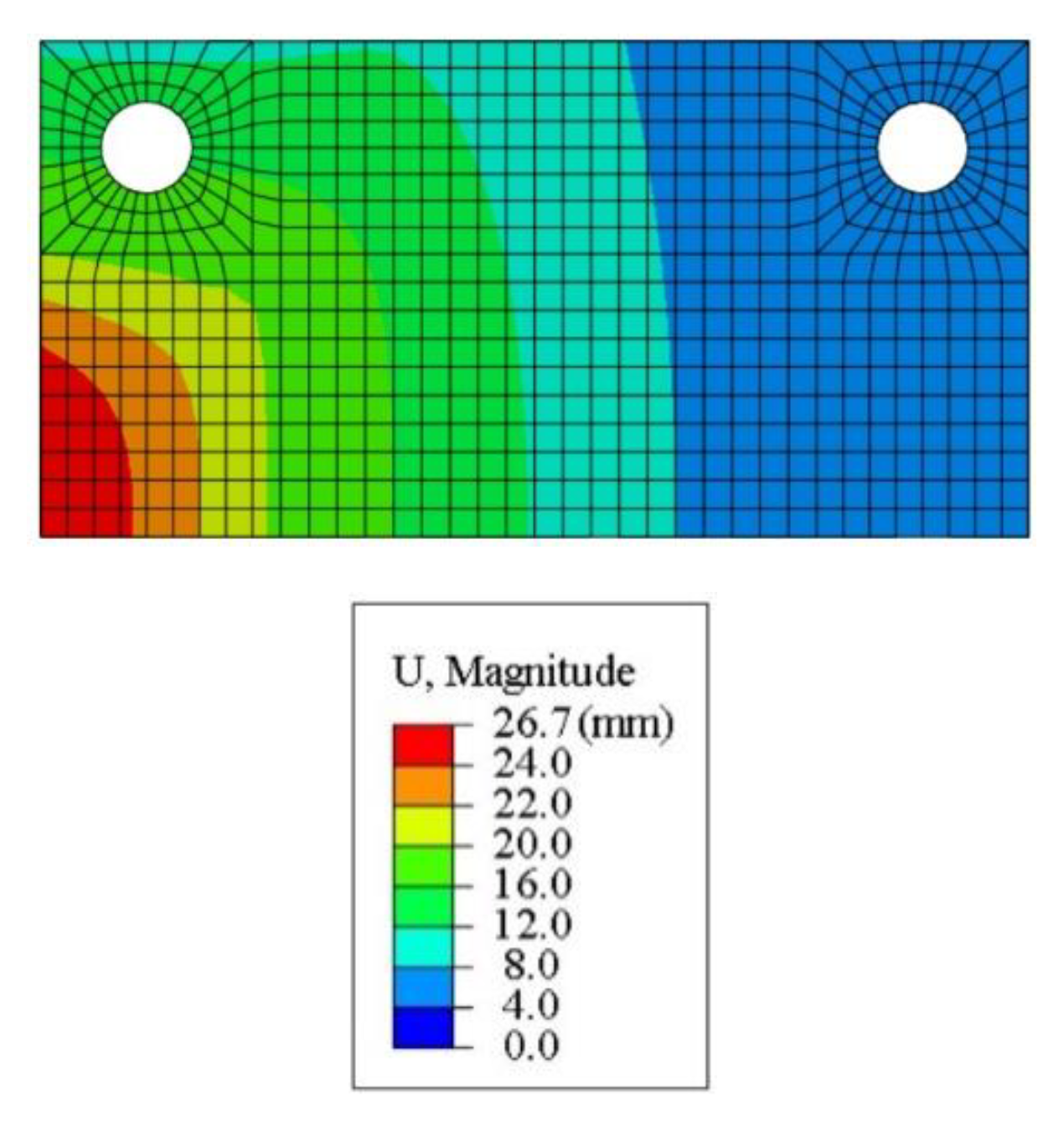
Figure 7.
Vertical displacement of the base plate in Test #1.
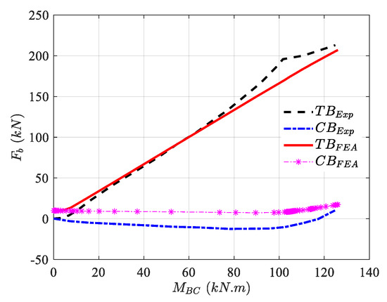
Figure 8.
Comparing the base moment vs. the anchor bolt force of Test #1 (data were extracted from Gomez et al. [6]) with Mesh 3 of the numerical model.
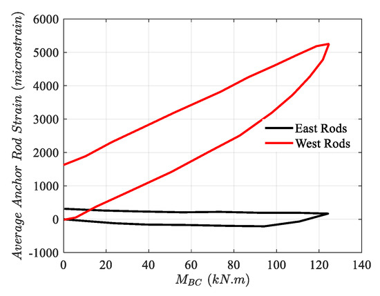
Figure 9.
Strain existence in the anchor bolt in the initial stage of connection loading (data were extracted from Gomez et al. [6]).

Figure 10.
Parametric sensitivity studies of the model based on the variation of the main components.
3.2. Moment vs. Column Drift
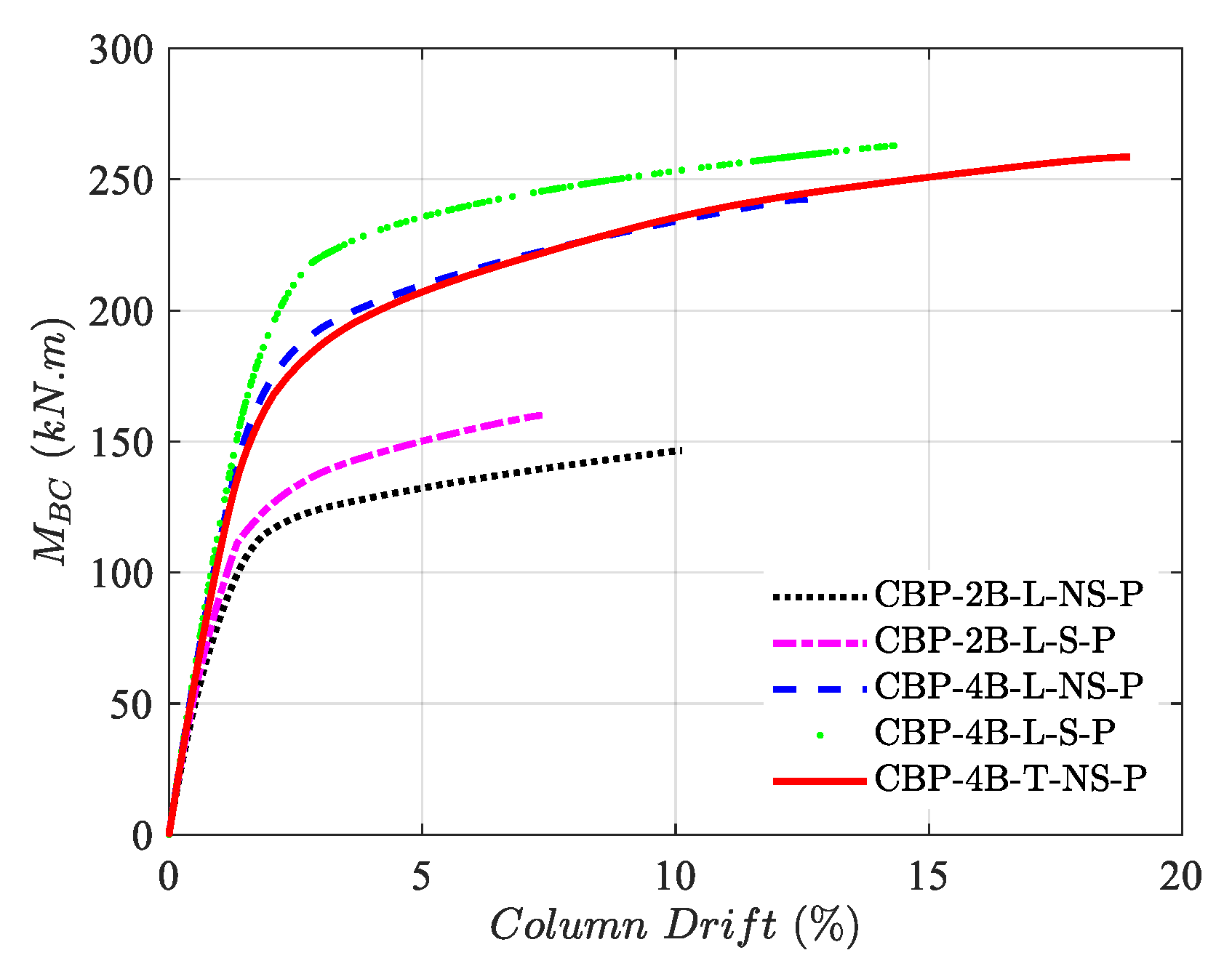
To monitor the global impact of each configuration on the column base plate connection with no column axial force, the moment vs. column drift curve can be seen in Figure 11. The vertical axis highlights the moment that the base plate experiences MBC, and the horizontal axis represents the corresponding column drift value. All the curves are comprised of linear and nonlinear regions. Comparing the performance of the basic model (CBP-2B-L-NS-P) with distinct configurations can represent each configuration’s effect on the behavior of the column base plate connection. Model CBP-2B-L-S-P, similar to the basic model with added stiffeners, indicates that although added stiffeners increased the strength of the connection, the connection exhibited reduced ductility (, , where and mean column drift at ultimate and yield displacement, respectively) and a column drift capacity. On the other hand, adding two more bolts on each compression and tension side (model CBP-4B-L-NS-P) with respect to the basic model improves the connection’s strength, rotation, and ductility. This increase can be attributed to the connection type behaving like a partial-strength connection, so strengthening the base plate region improves the whole joint performance.
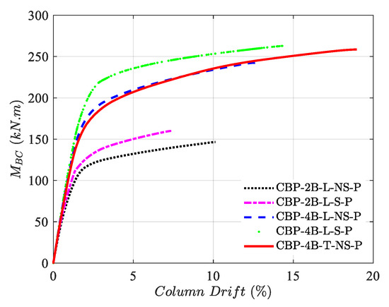
Figure 11.
Distinct column base plate configurations’ effect on the base moment vs. column drift.
Adding stiffeners beside more bolts, representing model CBP-4B-L-S-P, can improve the connection’s strength, stiffness, rotation, and ductility. Finally, in model CBP-4B-T-NS-P, which has the same material usage as CBP-4B-L-NS-P, only a small change in the bolt pattern results in a connection with the highest rotation, ductility, and strength among the proposed configurations. Therefore, despite the double strengthening in model CBP-4B-L-S-P (i.e., addition of stiffeners and bolts), model CBP-4B-T-NS-P, with only a slight change in the anchor bolt pattern, performed in a more ductile and deformable way than that with an almost similar ultimate strength. Modifying the bolt pattern can serve as a practical and economically viable solution when a connection demands both adequate strength and high ductility. Based on the expectations needed from the connection, various refinement solutions can be applied; however, due to the welding’s less reliable and time-consuming process compared to the bolting, substituting the stiffener with modified pattern anchor bolts can be an economical and efficient solution.
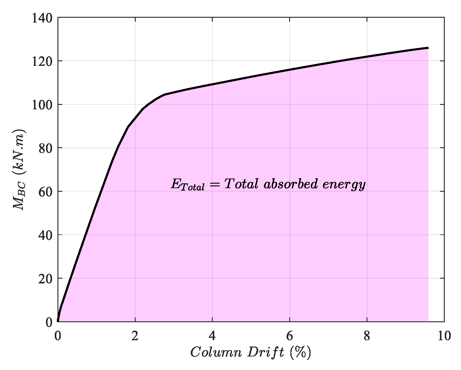
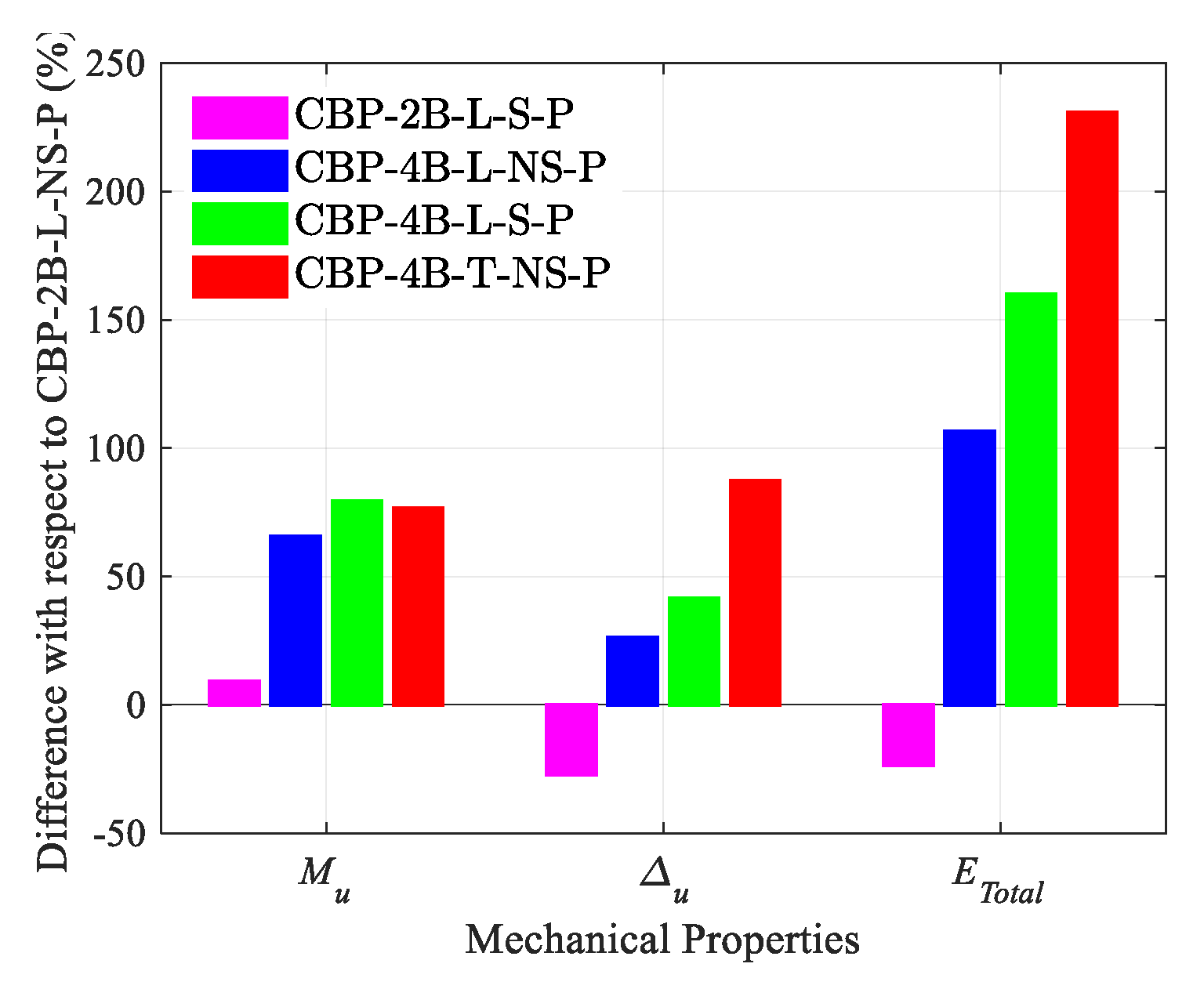
The mechanical properties of connections, specifically the ultimate strength Mu, ultimate column drift Δu, and total absorbed energy ETotal (area under the moment–column drift curve, see Figure 12), are subjected to a comparative analysis, which is shown in Figure 13 with respect to the basic model. Based on the results, it is clear that adding only the stiffener affects the strength, column drift, and absorbed energy by increasing, declining, and decreasing, respectively. Nevertheless, incorporating additional bolts in a straight arrangement enhances the ultimate strength, maximum column drift, and absorbed energy to a certain degree. Combining both the stiffener effect and more anchor bolts leads to improvements in the mentioned properties. Among distinct configurations, the trapezoidal anchor bolt pattern with no stiffener outperforms the remaining configurations, especially in the ductility and absorbed energy perspective.
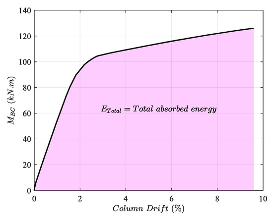
Figure 12.
The total absorbed energy calculation process.
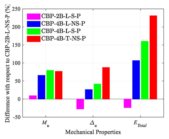
Figure 13.
Mechanical properties comparison of the refined models with the basic one.
3.3. Stress Distribution
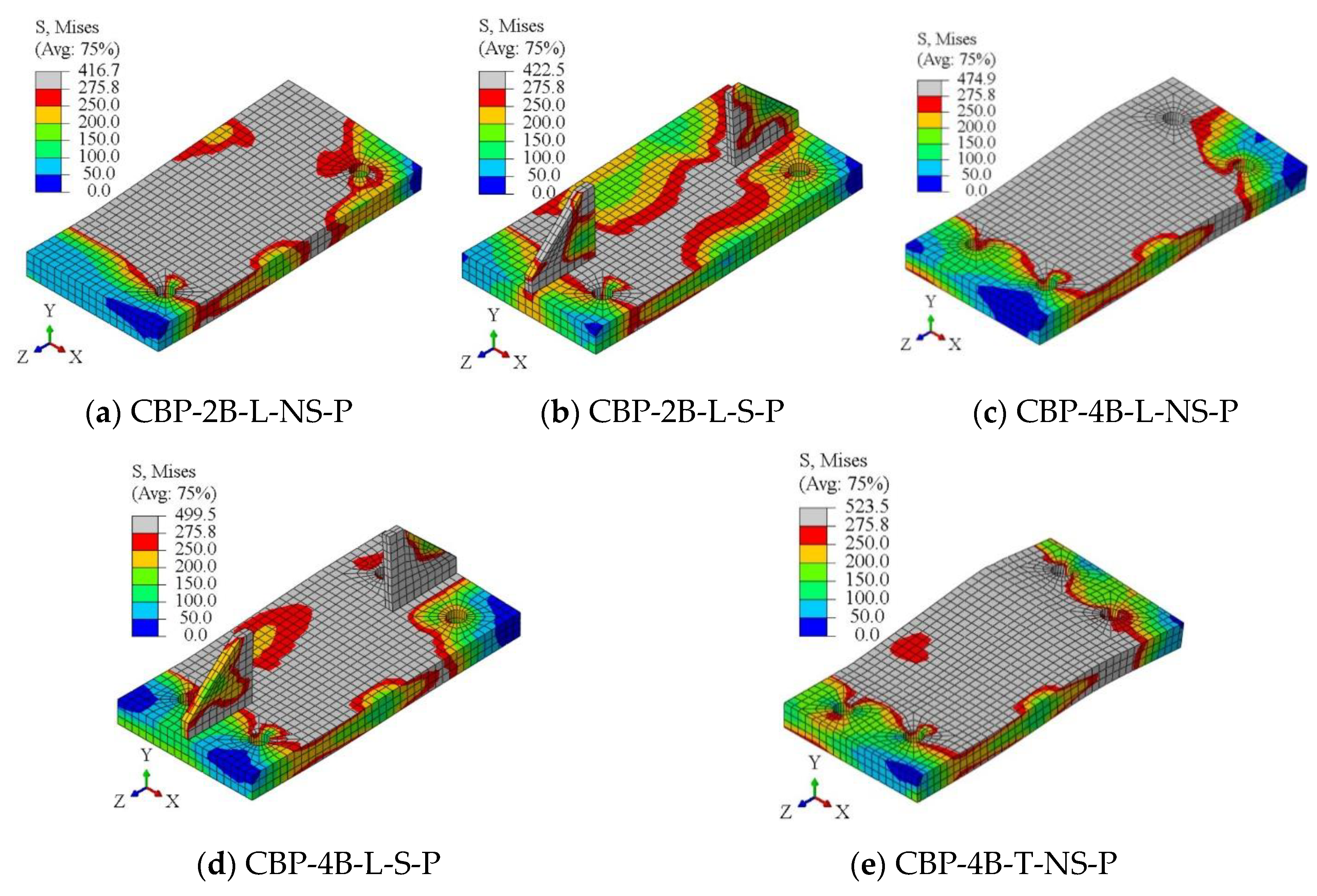
To investigate the classification of the connection based on the participation of each component, the Von Mises stress distributions on the base plate, column, and anchor bolts are illustrated in Figure 14, Figure 15 and Figure 16, respectively. Figure 14 represents the base plate yielding status in each configuration, highlighting the considerable participation of the base plate in the connection’s behavior. Also, based on the configuration type, the base plate’s yield pattern changes. For instance, incorporating stiffeners reduces the involvement of the base plate, whereas introducing additional anchor bolts alters the distribution of stress. Figure 15 shows that the column participates somewhat in the basic model and is considerably involved in the modified cases regarding the connection behavior.
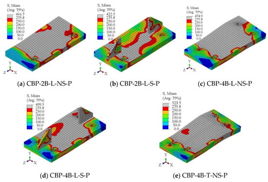
Figure 14.
Stress distribution on the base plate.
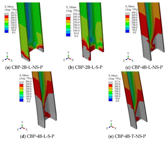
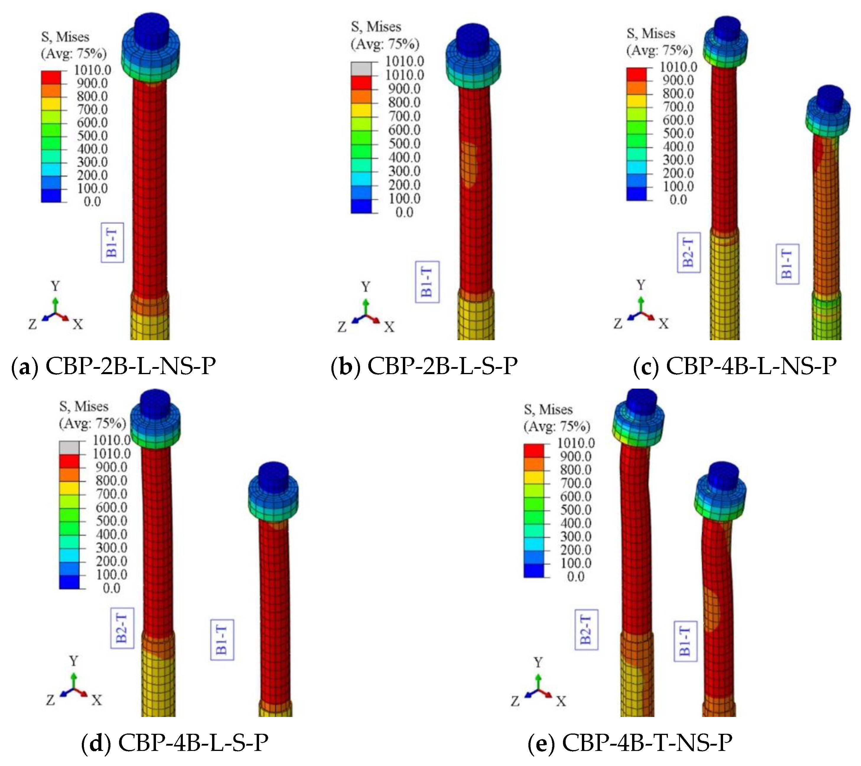
Figure 15.
Stress distribution on the column.

Figure 16.
Stress distribution on the anchor bolts.
Adding stiffeners and applying more anchor bolts increases the resistance of the connection, so an extra demand on behalf of the column can be applied, causing the column to experience more stress than the basic model. However, all the models experience the partial yielding of the column in the joint region. Additionally, it is evident that the anchor bolts have a considerable influence on the connection behavior, as they attain their ultimate strength (see Figure 16). According to the results, the anchor bolt failure dominates the ultimate failure of the connection. In the case of added extra bolts in a linear pattern, the inner anchor bolts considerably participate with respect to the outer ones; however, the anchor bolts bear an almost equal tensile force by using a trapezoidal pattern. Therefore, using a trapezoidal anchor bolt pattern leads to optimum usage of the base plate, column, and anchor bolts. Finally, based on the behavior of the components, the connection can be classified as a partial-strength connection.
3.4. Anchor Bolt Forces
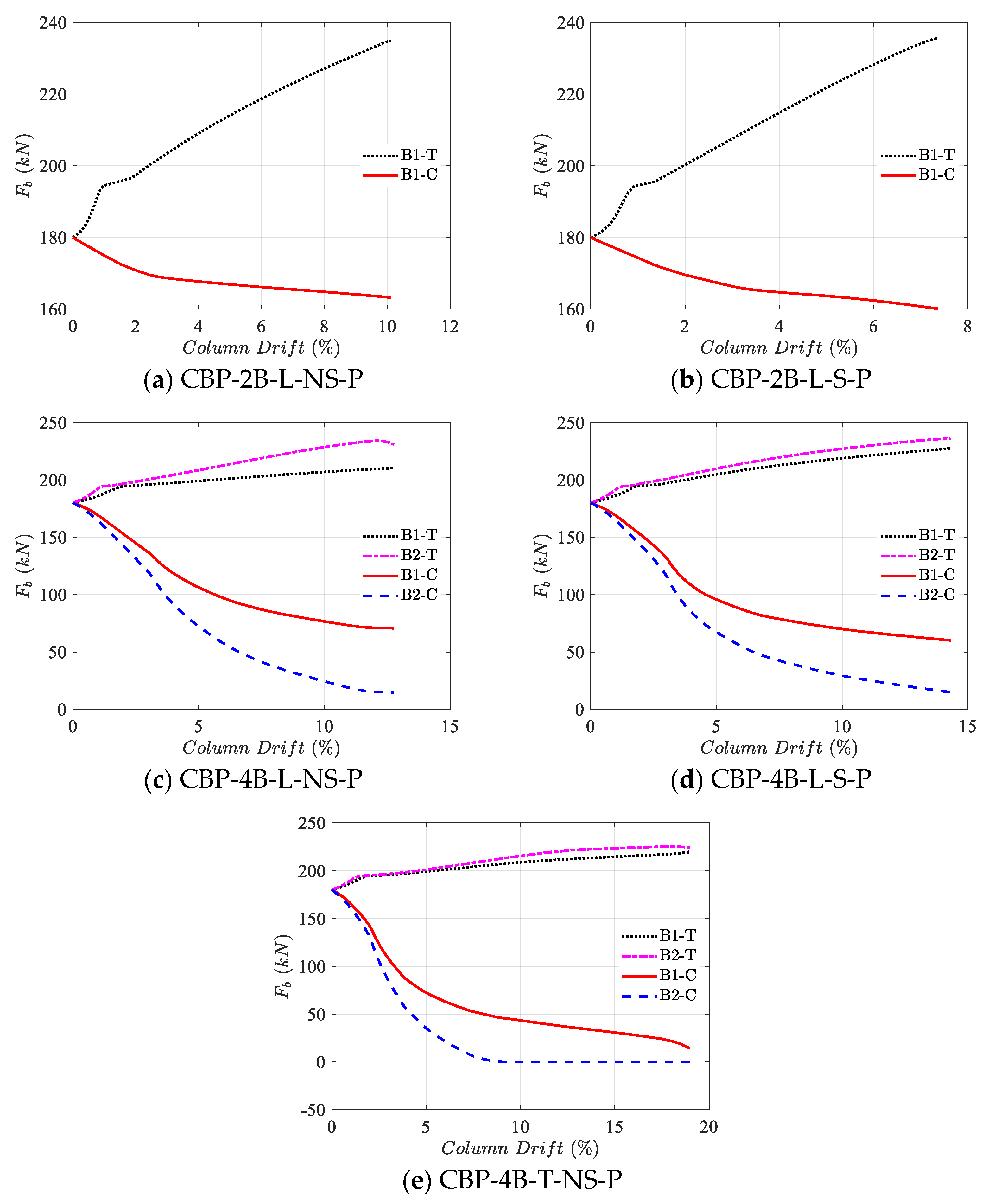
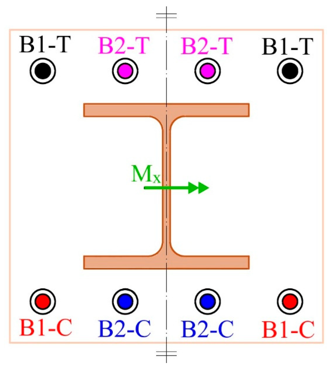
The anchor bolt behavior (a paramount component of the connection) plays a significant role in the connection’s performance. Since the models were symmetric in the Y-Z plane, only half the number of the anchor bolts were monitored. The axial force of the anchor bolt Fb is monitored in both the tensile and compression areas of the distinct connections, as shown in Figure 17. The legends in Figure 17 are compatible with the label assignments in Figure 18. Typically, the application of a bending moment causes an increase in the axial force of anchor bolts in the tensile areas and a decrease in the compression regions. Moreover, the normalized value of the anchor bolts’ force to their strength Rnb for distinct drift ratios is illustrated in Figure 19.
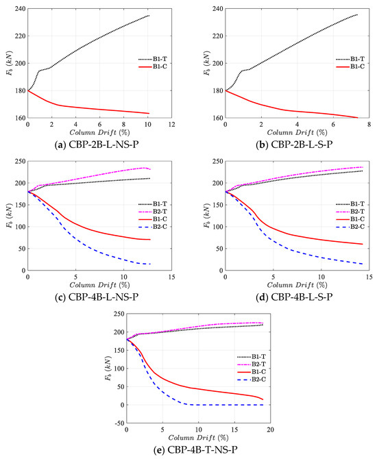
Figure 17.
Anchor bolts’ tensile force comparison under distinct column base plate configurations.
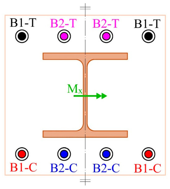
Figure 18.
Label assignment for the anchor bolts.
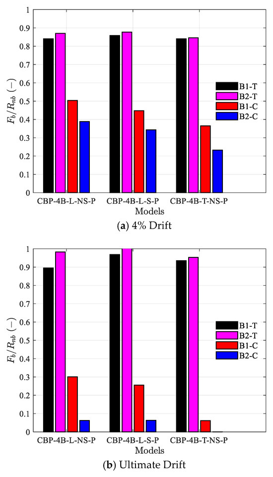
Figure 19.
Comparison of normalized Anchor bolts’ force between models in distinct drifts.
Adding stiffeners causes anchor bolts to fail with less of a column drift than the basic model with a similar pattern. In model CBP-4B-L-NS-P, the anchor bolts away from the column are less involved both in the tensile and compression regions of the connection than the closest ones, which is consistent with the findings of Fahmy et al. [4]. Therefore, the premature failure of the inner anchor bolts occurs compared to the outer ones. Adding a stiffener (CBP-4B-L-S-P) lessens the difference between the inner and outer anchor bolts, but again, the distinction exists. However, with a slightly changing bolt pattern in model CBP-4B-L-NS-P to the trapezoidal one (CBP-4B-T-NS-P), without using any extra material (stiffener), a considerable convergence in the axial force of the anchor bolts, especially in the tensile region, occurs, helping the load-bearing process of the connection in terms of strength, ductility, and energy absorption. Thus, the optimum usage of the materials is obtained in model CBP-4B-T-NS-P.
3.5. Column Axial Force Effect
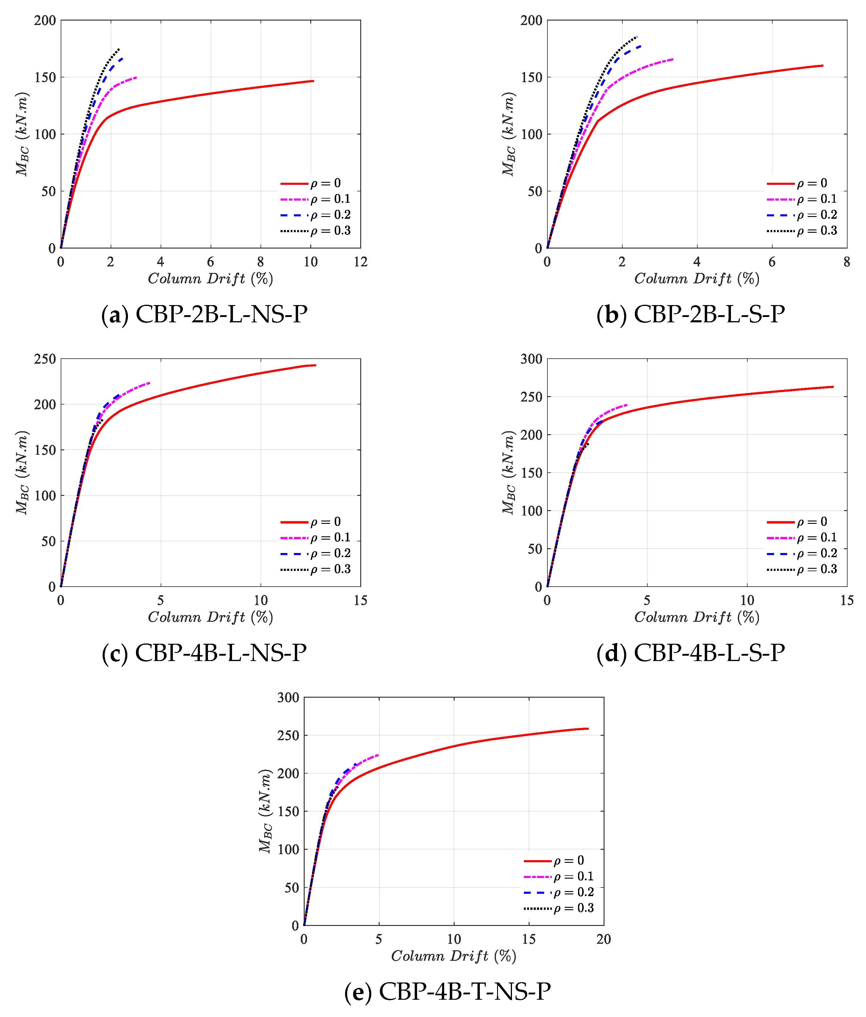
Figure 20 allows for an understanding of the effect of the column axial force on the connection’s behavior with distinct configurations. A general trend is that all the models fail with less column drift by increasing the axial force ratio of the column. Interestingly, in models CBP-2B-L-NS-P and CBP-2B-L-S-P, by increasing the column axial force, the moment resistance of the connection improves, while this issue is reversed in the remaining models.
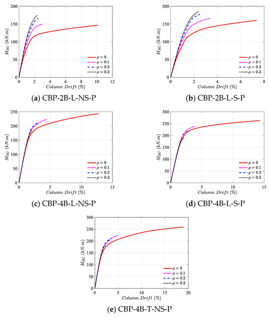
Figure 20.
Effects of column’s axial force ratio on the base moment vs. column drift of distinct column base plate configurations.
The reason behind the mentioned issue is that the base plate in the models CBP-2B-L-NS-P and CBP-2B-L-S-P is not restricted in the middle region and has flexibility. Hence, applying column axial force adds extra rigidity to the base plate and makes it participate more. On the other hand, in the remaining models, since extra anchor bolts are added in the middle region of the base plate, the flexibility is decreased; therefore, in this stage, the column axial force does not considerably affect the base plate, so the column dominates the behavior of the connection. Because the increase in the column axial force makes it buckle under lower bending moments, the resistance of these connections decreases by increasing the column axial force.
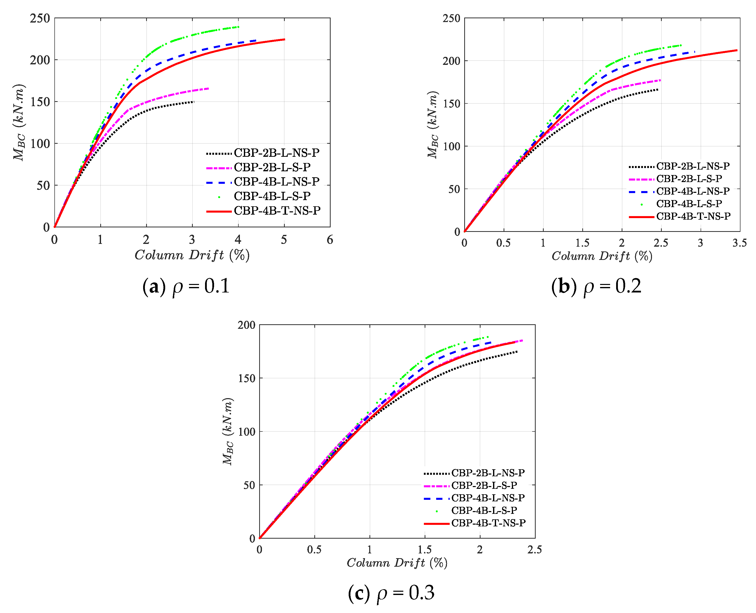
The effect of different configurations on the connection behavior under various column axial force ratios is shown in Figure 21. It is clear that by increasing the column axial force ratio, the dominant behavior of the connection changes from the base plate and anchor bolts to the column; thus, distinct configurations reach a somewhat similar behavior. However, similar to the no axial force condition, under all the studied column axial force ratios, model CBP-4B-T-NS-P outperforms the remaining models, especially from the ductility viewpoint.

Figure 21.
Distinct column base plate configurations’ performance under various axial force ratios of the column.
4. Conclusions
Due to the importance of the column base plate connections, the present study investigates different solutions to enhance their performance. To this end, different configurations of column base plate connections were studied numerically under bending moment and column axial force conditions. After generating a numerical model that was verified with experimental results, different configurations of the connection, from adding a stiffener to the anchor bolt pattern modification, were studied to monitor each approach’s pros and cons. The obtained results are summarized as follows:
- Although adding a stiffener to the column base plate connections increases the strength and stiffness, the ductility and rotation of the connection decrease.
- Adding more anchor bolts with rectangular patterns increases the strength, stiffness, and ductility, but results in non-uniform forces in the anchor bolts, thus leading to a non-rational use of the materials.
- Applying anchor bolts with a trapezoidal pattern improves mechanical properties and shares equal loads among inner and outer anchor bolts.
- Applying an axial force to the connection decreases the flexibility of the base plate; thus, column behavior dominates the connection’s performance in higher axial forces.
- An increase in the column axial force ratio decreases the rotation of the connection and makes it less ductile.
- Since the connection behaved as a partial-strength connection, all components’ behavior, such as the base plate, column, and anchor bolts, affected the connection’s behavior.
The column base plate with a trapezoidal pattern of the anchor bolts (CBP-4B-T-NS-P) provides a balance between economy and constructability in the building industry and outperforms the other configurations. Thus, concentrating on its behavior in detail seems valuable. Therefore, further studies can be performed to provide design guides for this connection type, in addition to conducting experimental studies, so that it can be utilized in the building industry.
Author Contributions
Conceptualization, R.K. and M.D.; methodology, R.K. and M.D.; software, R.K.; validation, R.K., M.D., and R.T.; formal analysis, R.K.; investigation, R.K., M.D., R.T., and Y.H.; resources, R.K., M.D., and R.T.; data curation, R.K.; writing—original draft preparation, R.K.; writing—review and editing, R.K., M.D., R.T., and Y.H.; visualization, R.K., M.D., and R.T.; supervision, M.D.; project administration, R.K. All authors have read and agreed to the published version of the manuscript.
Funding
This research received no external funding.
Data Availability Statement
The raw data supporting the conclusions of this article will be made available by the authors on request.
Conflicts of Interest
The authors declare no conflicts of interest.
Abbreviations
| Lp | base plate length |
| Bp | base plate width |
| ex | anchor bolt distance from the edge of the base plate, parallel to the column flange |
| ez | anchor bolt distance from the edge of the base plate along the column web direction |
| Pfi | anchor bolt distance from the column flange along the column web direction |
| gi | gauge distance between the anchor bolt parallel to the column flange |
| tp | base plate thickness |
| E | Young modulus of elasticity |
| fy | yield strength |
| fu | ultimate strength |
| εu | ultimate strain |
| ν | Poisson ratio |
| ε | eccentricity of the plastic potential surface |
| ψ | dilation angle |
| Kc | ratio of the second stress invariant on the tensile meridian to the compressive meridian at initial yield |
| fb0/fc0 | ratio of initial biaxial compressive yield stress to initial uniaxial compressive yield stress |
| CBP | column base plate |
| 2B | 2 anchor bolts |
| 4B | 4 anchor bolts |
| L | linear anchor bolt pattern |
| T | trapezoidal anchor bolt pattern |
| NS | non-existence of a stiffener |
| S | existence of a stiffener |
| P | pretensioned |
| go | outer gauge distance between the anchor bolt in the x-direction |
| pfo | distance between the anchor bolts in the z-direction |
| ρ | column axial force ratio |
| Ned | column’s axial demand |
| Npc | column’s axial plastic resistance |
| MBC | base moment |
| Fb | anchor bolt force |
| μ | ductility |
| Δu | column drift at ultimate displacement |
| Δy | column drift at yield displacement |
| Mu | ultimate strength |
| ETotal | absorbed energy |
References
- Zareian, F.; Kanvinde, A. Effect of column-base flexibility on the seismic response and safety of steel moment-resisting frames. Earthq. Spectra 2013, 29, 1537–1559. [Google Scholar] [CrossRef]
- Grilli, D.; Jones, R.; Kanvinde, A. Seismic performance of embedded column base connections subjected to axial and lateral loads. J. Struct. Eng. 2017, 143, 04017010. [Google Scholar] [CrossRef]
- Thambiratnam, D.P.; Paramasivam, P. Base plates under axial loads and moments. J. Struct. Eng. 1986, 112, 1166–1181. [Google Scholar] [CrossRef]
- Fahmy, M.; Stojadinovic, B.; Goel, S.C. Analytical and experimental studies on the seismic response of steel column bases. In Proceedings of the 8th Canadian Conference on Earthquake Engineering, Vancouver, BC, Canada, 13–16 June 1999. [Google Scholar]
- Fisher, J.M.; Kloiber, L.A. Steel Design Guide Series 1–Base Plate and Anchor Rod Design, 2nd ed.; American Institute of Steel Construction: Chicago, IL, USA, 2006. [Google Scholar]
- Gomez, I.; Kanvinde, A.; Deierlein, G. Exposed Column Base Connections Subjected to Axial Compression and Flexure; AISC: Chicago, IL, USA, 2010. [Google Scholar]
- Kanvinde, A.; Jordan, S.; Cooke, R. Exposed column base plate connections in moment frames—Simulations and behavioral insights. J. Constr. Steel Res. 2013, 84, 82–93. [Google Scholar] [CrossRef]
- EN 1993-1-8; Eurocode 3—Design of Steel Structures—Part 1–8: Design of Joints. European Committee for Standardization (CEN): Brussels, Belgium, 2005.
- Latour, M.; Rizzano, G. Full strength design of column base connections accounting for random material variability. Eng. Struct. 2013, 48, 458–471. [Google Scholar] [CrossRef]
- Latour, M.; Rizzano, G. A theoretical model for predicting the rotational capacity of steel base joints. J. Constr. Steel Res. 2013, 91, 89–99. [Google Scholar] [CrossRef]
- Latour, M.; Piluso, V.; Rizzano, G. Rotational behaviour of column base plate connections: Experimental analysis and modelling. Eng. Struct. 2014, 68, 14–23. [Google Scholar] [CrossRef]
- Shaheen, M.A.; Tsavdaridis, K.D.; Salem, E. Effect of grout properties on shear strength of column base connections: FEA and analytical approach. Eng. Struct. 2017, 152, 307–319. [Google Scholar] [CrossRef]
- Díaz, H.; Nuñez, E.; Oyarzo-Vera, C. Monotonic response of exposed base plates of columns: Numerical study and a new design method. Metals 2020, 10, 396. [Google Scholar] [CrossRef]
- Kabir, M.A.B.; Hasan, A.S.; Billah, A.M. Failure mode identification of column base plate connection using data-driven machine learning techniques. Eng. Struct. 2021, 240, 112389. [Google Scholar] [CrossRef]
- Pan, J.; Huang, R.; Xu, J.; Wang, P.; Wang, Z.; Chen, J. Behavior of exposed column-base connections with four internal anchor bolts under seismic loading. Structures 2021, 34, 105–119. [Google Scholar] [CrossRef]
- Song, B.; Galasso, C.; Kanvinde, A. Reliability analysis and design considerations for exposed column base plate connections subjected to flexure and axial compression. J. Struct. Eng. 2021, 147, 04020328. [Google Scholar] [CrossRef]
- Mehdi, B.C.; Boumechra, N.; Missoum, A.; Bouchaïr, A. Connection of a Steel Column Base Plate: Mechanical Behavior and Stiffening Effects. Open Civ. Eng. J. 2022, 8, 1764–1786. [Google Scholar]
- Torres-Rodas, P.; Medalla, M.; Zareian, F.; Lopez-Garcia, D. Cyclic behavior and design methodology of exposed base plates with extended anchor bolts. Eng. Struct. 2022, 260, 114235. [Google Scholar] [CrossRef]
- Al-Sharmootee, M.; Lavassani, S.H.; Hosseini, M.H.; Ali, M. The cyclic performance of column base plate connections using different types of stiffeners. Can. J. Civ. Eng. 2023, 51, 449–460. [Google Scholar] [CrossRef]
- Shaheen, M.A.; Tsavdaridis, K.D.; Ferreira, F.P.V.; Cunningham, L.S. Rotational capacity of exposed base plate connections with various configurations of anchor rod sleeves. J. Constr. Steel Res. 2023, 201, 107754. [Google Scholar] [CrossRef]
- Aichouche, M.E.A.; Abidelah, A.; Bouchair, A.; Kerdal, D.E.-D.; Seghir, A.; Vatansever, C. Effects of stiffeners on anchor rod flexural strength in column base-plate connections. J. Constr. Steel Res. 2024, 222, 108983. [Google Scholar] [CrossRef]
- Nawar, M.T.; Matar, E.; El-Zohairy, A.; Alaaser, A.; Maaly, H. Experimental and FE analysis of the behavior of steel column base connections under tension and bending moment. Structures 2024, 62, 106164. [Google Scholar] [CrossRef]
- Kiamanesh, R.; Abolmaali, A.; Razavi, M. Effect of circular bolt pattern on behavior of extended end-plate connection. J. Struct. Eng. 2013, 139, 1833–1841. [Google Scholar] [CrossRef]
- Morrison, M.; Quayyum, S.; Hassan, T. Performance enhancement of eight bolt extended end-plate moment connections under simulated seismic loading. Eng. Struct. 2017, 151, 444–458. [Google Scholar] [CrossRef]
- El Kalash, S.N.; Hantouche, E.G. Prying effect in unstiffened extended endplate connection with circular bolts configuration. J. Constr. Steel Res. 2019, 160, 402–410. [Google Scholar] [CrossRef]
- Khani, R.; Hosseinzadeh, Y.; Hoseinzadeh, M. Asl, Improving the T-stub component behavior tied to a rigid base. J. Constr. Steel Res. 2023, 211, 108199. [Google Scholar] [CrossRef]
- EN 1992-1-1; Eurocode 2: Design of Concrete Structures—Part 1-1: General Rules and Rules for Buildings. CEN: Brussels, Belgium, 2004.
- Sümer, Y.; Aktaş, M. Defining parameters for concrete damage plasticity model. Chall. J. Struct. Mech. 2015, 1, 149–155. [Google Scholar]
- He, J.C.W.; Clifton, C.; Ramhormozian, S. Numerical parametric analysis of gravity column base-plate connections. J. Constr. Steel Res. 2023, 204, 107846. [Google Scholar] [CrossRef]


Disclaimer/Publisher’s Note: The statements, opinions and data contained in all publications are solely those of the individual author(s) and contributor(s) and not of MDPI and/or the editor(s). MDPI and/or the editor(s) disclaim responsibility for any injury to people or property resulting from any ideas, methods, instructions or products referred to in the content. |
© 2025 by the authors. Licensee MDPI, Basel, Switzerland. This article is an open access article distributed under the terms and conditions of the Creative Commons Attribution (CC BY) license (https://creativecommons.org/licenses/by/4.0/).