Abstract
Concerning building acoustics, the impact of sound propagation in the building structure can be considered one of the most relevant problems. Floating floors are an efficient solution, composed of a rigid walking surface above a resilient material. Functioning as a spring, the resilient layer must have adequate damping properties and compressive strength against permanent and imposed loads to guarantee its performance over time. In this context, this study aims to completely evaluate the impact sound reduction of composite lightweight floating floors formed by ceramic tiles and recycled rubber mats when subjected to prolonged loads, from material characterization to their application in a hypothetical scenario. This study was based on the dynamic stiffness (ISO 9052-1) and compressive creep (ISO 16534) of the resilient layer and the physical characterization of the ceramic tiles, predicting the present and future (15 years) impact sound reductions and their application in a hypothetical room, considering direct and indirect transmissions paths (ISO 12354-2). The results showed that the lightweight floating floor compositions lost their damping capability to a degree that can reduce their weighted reduction in the impact sound pressure level by up to 2 dB over prolonged periods (15 years). Howsoever, the compositions had considerable initial impact sound insulation capability and adequate performance maintenance over time.
1. Introduction
In the field of acoustics, impact sound propagation in the building structure can be considered one of the most relevant problems regarding building acoustics. The sound sources range from footstep noise to vibrations caused by equipment in the building, and the propagation of the sound energy occurs through the structural elements to areas in the building far from the emitting source. The sound energy propagated by the building structure is radiated by the walls, floors and ceilings surfaces, being perceived by its users [1,2,3,4].
When evaluating uncoated structural slab systems, mainly with slabs with a minimum thickness (defined by structural and fire resistance criteria), it is notable that their acoustic sound insulation against impact noise is inadequate to the building user’s comfort. To increase the impact sound insulation of structural slab systems, floor covering systems can be used, using materials that, combined, can promote vibration damping and an adequate walking surface [5,6,7].
Lightweight floating floors are one of the solutions that benefit from this concept, having a lightweight rigid walking surface, such as ceramic tiles for example, and a continuous resilient base underneath, responsible for disconnecting the floating walking surface from the structural slab [4,8].
To understand how vibration isolation principles work, it is important to perform a behavioral analysis of systems with one degree of freedom, as illustrated in Figure 1. In this system, composed of a spring element (stiffness—k), a mass (m) and a damper (damping coefficient—C), the mass is excited by an external periodic force (F), and the displacement (x) caused by its action is a function of the quotient between the vibration speed and the frequency of occurrence [9].
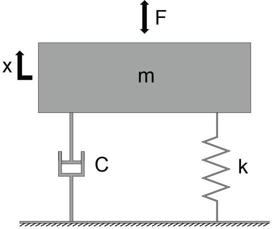
Figure 1.
Vibrational system with one degree of freedom and excitation in the floating element.
In this case, the basic properties of this vibrating system are formed by the inertia of the mass, responsible for accumulating kinetic energy, and the rigidity of the spring element, which accumulates potential energy. Furthermore, the external force introduces energy into the system, and the damping provided by the shock absorber has the function of dissipating the energy present in the forced displacement. The damping capacity affects the rate of reduction of the oscillatory movement but only has a weak influence on the vibration frequency. In this sense, it is of interest to indicate that the displacement does not occur in phase with the external force due to the damping coming from the shock absorber [9,10,11,12].
In the absence of excitation from an external force, the system vibrates in a sinusoidal manner at a constant amplitude (dependent on the amplitude generated by the initial excitation), at its natural frequency (f0) [9].
In the case of estimating the acoustic performance of floating floors, the walking surface is disconnected from the supporting slab by means of a resilient material, with no rigid connections to the elements and boundary walls at the perimeter of the floor system. The resilient interface between the covering and the slab results in a mass–spring type resonance associated with the floating floor. Due to the elastic and damping characteristics of the resilient layer, these systems are quite efficient in reducing the transmission of impact sounds [8,13].
In cases in which the mass and impedance (opposition to movement in terms of the force–displacement relationship) of the floor slab is much higher than that of the floating floor, the resonance frequency of the mass–spring system of the covering surface is approximately the same as that of a mass–spring–mass system that includes the floor slab system. In this case, the design of these systems should aim to obtain a resonance frequency well below the frequency range of interest in building acoustics. This is because the floor covering can have an undesirable effect, resulting in a negative reduction in impact sound pressure level values, reducing the performance of the system in certain frequency bands [2,8].
Regarding the resilient layer, its action occurs as a series of springs with small spacing between them (considering only its dynamic stiffness—s′), being treated in this way since its thickness is reduced to the point of not supporting wave movements within the frequency range of interest. Although the floating layer is characterized by its mass and stiffness, its stiffness is not considered in the estimation of the capacity to reduce impact sounds. In this case, the excitation generated by an impact is transmitted from the walking surface to the support slab by means of the resilient material [2,8,14,15].
In the case of lightweight floating floors, the impedance of the impacts must be considered as the frequency increases. This is mainly due to the combination of lower rigidity and greater internal energy dissipation capacity, when compared to heavy floating floors (floating mortar or concrete), generating a more local reaction in the floor system. Therefore, the reduction in energy imparted by the impacts above the limit frequency must be considered [2,8,14].
Also, the use of resilient layers to form floating floor systems increases the impact sound attenuation but implies the necessity of this material to support the permanent and imposed loads applied to the flooring system under normal use conditions over time. The resilient material also needs to have adequate compressive strength to sustain these loads applied to the floor for long periods of time to guarantee performance conservation over the service life of the building [8].
Due to their resilient properties, sustained loads modify the material’s internal structure arrangement, impacting and decreasing its original performance due to the reduction in thickness. This reduction in overall thickness results in a decrease in the material damping capacity, since the dynamic stiffness, a product of the resonance frequency, is inversely proportional to the material thickness. The damping efficiency of the resilient material against impact sound is reduced when its dynamic stiffness increases. This also increases the vibrational waves’ propagation speed in the material, transferring more energy from the walking surface to the structural slab [16,17,18,19].
Thus, this article aimed to evaluate the impact sound reduction of four different compositions of ceramic tile and rubber mat lightweight floating floors over time in the presence of loads usually present in buildings from material characterization to their application in a hypothetical scenario.
2. Materials and Methods
The analyzed lightweight floating floor was composed of a rigid walking surface (ceramic tile) with a resilient layer underneath (recycled rubber mat), as shown in Figure 2. The ceramic tiles were adhered to the resilient layer by a thin epoxy adhesive in the ceramic tile’s corners and center.
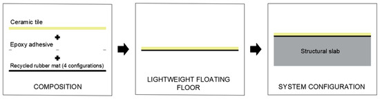
Figure 2.
Composition of the lightweight floating floor.
This study analyzed four different recycled rubber mat compositions available on the market, of varying thickness and density, produced with the same raw material and manufacture process (sintering fabrication method with recycled rubber granules subjected to high temperature and pressure conditions to promote re-vulcanization), as shown in Figure 3. To form the lightweight floating floor with rubber mats, the same ceramic tile was used in all compositions. The materials and the identification code used in this research are present in Table 1.
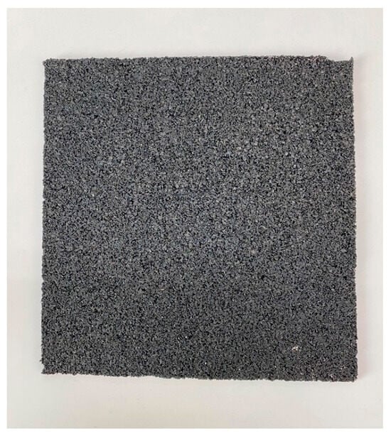
Figure 3.
Recycled rubber mat sample (200 × 200 mm).

Table 1.
Physical properties of the materials.
These rubber agglomerate compositions were defined based on the technical limitations imposed by the manufacturing process, both in terms of machinery and the manufacturer’s availability to develop special compositions. Furthermore, considering the manufacturing limitations, the compositions used had characteristics that are suitable for those commonly used in this type of material, when compared with other studies and products available on the market [17,20,21,22,23].
The acoustic properties were determined in terms of the present dynamic stiffness, compressive creep, the impact sound reduction capability and its performance under a hypothetical application (at present and after a 15-year loading). Usually, the designed project life of a building is much more than 15 years, but due to the time required to perform the compressive creep test, this study was limited to a 15-year load extrapolation.
The dynamic stiffness was determined by the resonant frequency of each system that contains the resilient layer. The tests followed the prescriptions of ISO 9052-1 [24] and were conducted in the Building Department of Laboratório Nacional de Engenharia Civil (LNEC—Portugal). The tests were conducted in three 200 × 200 mm samples of each recycled rubber mat, placed on a rigid base and underneath an 8 kg steel plate, simulating the usually found 200 kg/m2 load in residential buildings.
To determine the resonant frequency of the systems, the steel plate was excited by a vertical impact in the center of the plate, by a Brüel and Kjaer Type 8208 impact hammer with a soft tip, and a Brüel and Kjaer piezoelectric accelerometer Type 4383 was magnetically coupled to the center of the steel plate. The data acquisition was carried out with a multi-channel PULSE Type 3560-D analyzer with a charge converter DeltaTron Type 2646. The frequency width of the analysis was 0 to 200 Hz, with a data sample of 200 lines and a signal acquisition period of one second after the impact, resulting in a frequency resolution of 1 Hz. Ten impacts were conducted to average the resonant frequency of each sample.
Given the negligible influence of the air present in the recycled rubber mat material, supported by Asdrubali and D’Alessandro [25], Schiavi, Guglielmone and Miglietta [26] and Rindel [19], the dynamic stiffness was taken as the apparent dynamic stiffness, obtained by the resonant frequency, following Equation (1):
where s′ is the dynamic stiffness per unit area, in MN/m3; m′t is total mass per unit area used during the test (steel plate plus accelerometer mass), in kg/m2; fr is the resonant frequency of the system, in Hz.
In another field, the compressive creep of the resilient layers was conducted in the itt Performance (Unisinos–Brazil) Acoustics Laboratory, following ISO 16534 [27] prescriptions. Three 200 × 200 mm samples of each recycled rubber mat compositions were placed underneath an 8 kg steel plate.
The strain of the loaded material was measured by a strain gauge with a 0.01 mm resolution. The material strain was measured after the loading imposition over the material after 1 min, 1 h, 5 h and in the following intervals: 1, 2, 4, 7, 9, 11, 14, 18, 24, 32, 42, 53, 65, 80, 100, 123, 156 and 190 days.
A polynomial regression with a logarithmic base was developed with the strain results of each sample over time to estimate the compressive creep of the material over 15 years (131.400 h of loading), corresponding to 30 times the test duration. The equations obtained with the polynomial regression had determination factors ranging from 0.90 to 0.96, indicating that the models can replicate the observed outcomes very well.
Considering the estimated 15 years strain of each sample, the future resonant frequency was calculated by Equation (2) to obtain the future dynamic stiffness of the material:
where fr,15years is the resonant frequency after 15 years of loading, in Hz; fr is the present resonant frequency, in Hz; ds is the material thickness under a 250 Pa load, in mm; X15years is the estimated compressive strain of the material, in mm; X0 is the material strain 60 s after the test load imposition, in mm.
With the calculated dynamic stiffness of the resilient layer (present and after 15 of loading) and the mass per unit area of the walking surface, the natural frequency of the lightweight floating floor was determined by Equation (3):
where f0 is the natural frequency of the floating floor, in Hz; s′ is the dynamic stiffness per unit area of the resilient layer, in MN/m3; m’ is the mass per unit area of the walking surface, kg/m2.
Also, the limit frequency of the lightweight floating floor was obtained by Equation (4) to determine the reduction in the impact sound pressure level of each composition:
where flimit is the limit frequency, in Hz; ρ is the density of the walking surface, in kg/m3; cL is the quasi-longitudinal phase wave velocity of the walking surface, in m/s; h is the thickness of the walking surface, in m; m is the mass of one of the tapping machine hammers, equal to 0.5 kg.
According to Cremer, Hackl and Petersson [14], Hopkins [8] and Vigran [2], due to the lightweight characteristics of this type of floating floor, having a lower stiffness and greater capacity of internal damping, the impedance of the impacts needs to be considered from the limit frequency. Thus, below the limit frequency, the reduction in the impact sound pressure level was calculated from Equation (5), and above the limit frequency, it was obtained from Equation (6). The data were calculated in one-third octave bands, from 100 to 3.150 Hz, and the equations were adjusted from real-size laboratory test specimens, conducted according to ISO 10140-5 [28]:
where ΔL is the reduction in the impact sound pressure level, in dB; f is the frequency, in Hz; f0 is the natural frequency of the floating floor, in Hz; m is the mass of one of the tapping machine hammers, equal to 0.5 kg; ρ is the density of the walking surface, in kg/m3; cL is the quasi-longitudinal phase wave velocity of the walking surface, in m/s; h is the thickness of the walking surface, in m.
For all the frequency bands below the natural frequency of the lightweight floating floor, it was considered that ΔL = 0, and the weighted reduction in the impact sound pressure level (ΔLw) was calculated according to ISO 717-2 [29].
Lastly, to evaluate the capability of the lightweight floating floor compositions in a real residential building scenario, a hypothetical building was developed with defined materials, dimensions and contour conditions. The rooms were adjacent vertically, with masonry walls and a solid reinforced concrete slab (8 cm thickness). The airborne sound insulation and physical data of the masonry wall were taken from the Oliveira et al. [30] study. The reinforced concrete impact sound levels, airborne sound insulation and sound radiation properties were calculated according to Hopkins [8]. A scheme of the room’s dimensions and composition is presented in Figure 4.
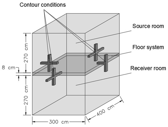
Figure 4.
Configuration of the hypothetical rooms.
Then, considering only the recycled rubber mat with the greater acoustic performance loss over time, the standardized impact sound pressure level (L’nT) of the floor system with and without the lightweight floating floor (in both conditions—at present and after 15 years of use), considering the direct, indirect and flanking transmission paths through the walls and slab, was calculated according to ISO 12354-2 [31], following Equation (7). Also, the weighted standardized impact sound pressure level (L’nT,w) was calculated according to ISO 717-2 [29]:
where L′nT is the standardized impact sound pressure level of the flooring system, in dB; Ln,situ,d is the normalized impact sound pressure level due to impact direct transmission in situ, in dB; Ln,ij is the normalized impact sound pressure level due to flanking transmission, in dB; V is the volume of the receiving room, in m.
This simulation of the acoustic behavior of the lightweight floating floor with a structural slab in a real use scenario is a limitation of the research but was carried out considering all the theoretical methods and most realistic input data to better represent an in situ condition.
To exemplify and evaluate the performance level loss over time, the predicted results for the lightweight floating floor in a hypothetical residential building scenario were compared with the Brazilian performance levels presented in NBR 15575-3 [32].
3. Results and Discussion
To analyze the behavior of the recycled rubber mats submitted to prolonged loading periods, in Table 2 are present the results obtained in the compressive creep test in terms of the initial strain (X0), the strain at the end of the test (Xct; 4560 h), the estimated strain after 15 years of loading (X15years) and the relative strain (ε15years) with a 200 kg/m2 load.
Table 2.
Compressive creep results for a 200 kg/m2 load.
The initial strain results indicate a low immediate strain on the material in the presence of a common load in buildings for all the analyzed compositions. Among the four compositions analyzed, the initial strain did not follow the expected behavior in terms of density, where a greater density of the same material tended to strain less when subjected to the same loading conditions. This variation can be explained by the initial accommodation of the loading plate and the material, as well as measurement uncertainties attached to the low difference in thickness in the initial test moments.
Due to the physical property discrepancies (only two of the four rubber mat compositions had the same density, and none of the compositions had the same thickness), a correlation in terms of density or thickness between each sample result was unfeasible. However, despite the correlation impossibility, the greatest strain at the end of the test was verified in the composition with the lowest thickness and density.
In terms of the predicted strain for a 15-year load upon the resilient layer, the reduction in thickness was registered between 0.94 and 1.34 mm, being more representative in lower-thickness rubber mat compositions. In this case, for the composition with a 2.0 mm thickness, a 62% loss of the initial thickness is expected after the prolonged load, leaving less than half of the initial material thickness. This behavior is probably explained by an internal structural web with fewer rubber granules per volume, measured by the 39% porosity, resulting in a greater strain expectation when the system is loaded. Such thickness loss over time is not so serious due to the low representativeness of the strain value (1.32 mm) in the visual aspect and finish of the flooring system along the walls.
Additionally, a lower relative thickness loss was verified in the compositions with greater thickness and density, indicating a more efficient internal structure of the rubber granule structure to transfer the load through the material layer.
To analyze the damping properties of the recycled rubber mat resilient layers, Figure 5 shows the present and future (predicted from the compressive creep test) dynamic stiffnesses.
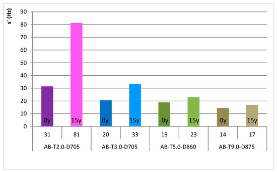
Figure 5.
Present and future dynamic stiffness.
As expected from the theorical references, the dynamic stiffness of a resilient layer is inversely proportional to its thickness, resulting in an increase in dynamic stiffness when there is a reduction in thickness. This can occur by the direct action of a load upon the resilient layer, increasing its internal static pressure and, consequently, resulting in an increase in the phase velocity propagation speed of vibration waves through the material, reducing its damping capability [9,19].
In this way, the data obtained from the experimental tests state the expected behavior when the material is loaded for prolonged periods, with an increase in the dynamic stiffness of all recycled rubber mat compositions. The magnitude of the difference in the present and future dynamic stiffnesses is a product of the estimated strain for 15 years, resulting in a more significant loss of damping capability in the RC-T2.0-D705 composition.
Additionally, the resonant frequency tests needed to determine the dynamic stiffness showed very similar damping capabilities among the rubber mat compositions, with a 0.25 loss factor in the AB-T2.0-D705 samples and 0.20 in the other three compositions, indicating that 20 to 25% of the vibrational energy imposed in these resilient materials is converted to other components inside the material.
Moreover, considering the application of the resilient layer with the ceramic tiles, to form the lightweight floating floor, the spectrum of the reduction in the sound pressure levels is linear and increases with frequency. Considering the present and future impact sound reduction capabilities, the performance of all compositions decreased with time for all frequency bands, demanding an exhaustive number of graphs to lead to the same evaluation. In this case, to explore the loading impact over time, the natural frequency of the lightweight floating floor compositions is presented in Figure 6.
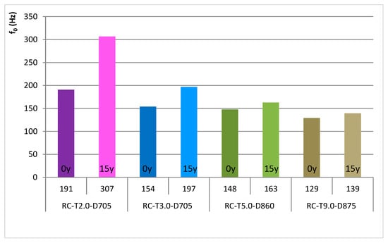
Figure 6.
Present and future natural frequency of the lightweight floating floor compositions.
Evaluating the natural frequency shift in the lightweight floating floor compositions, due to the increase in dynamic stiffness, the results followed the expected and seen behavior, with increases in the natural frequency of the systems after 15 years of loading upon the floor. These increases were more relevant in the RC-T2.0-D705 composition, where two 1/3 octave central frequency bands of impact sound reduction capability were lost, reducing the efficiency of the system in the building acoustics frequency range. Due to the metrics used to evaluate the acoustic performance against impact sounds (ISO 717-2 [29] reference curve spectrum), these two 1/3 octave central low-frequency band reductions can directly influence the overall performance of a flooring system when fully analyzed in a real building situation, in terms of its weighted standardized impact sound pressure level (L′nT,w).
For the RC-T3.0-D705 and RC-T5.0-D860 compositions, the increase in the natural frequency caused a reduction in efficiency of one 1/3 octave central frequency band. Considering the RC-T9.0-D875 composition, its natural frequency increase was not enough to cause a loss in the frequency width of the system efficiency against impact sounds.
Lastly, to visualize the performance loss of the lightweight floating floor compositions over 15 years of loading upon the floor, Figure 7 illustrates their present and future weighted reductions in impact sound pressure level.
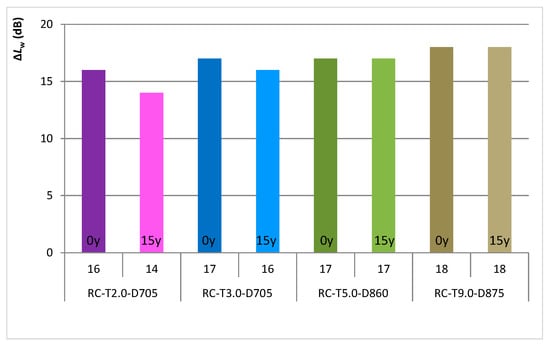
Figure 7.
Present and future weighted reduction in impact sound pressure level of the lightweight floating floor compositions.
The prolonged loading period had a negative effect on the performance of the flooring systems, as seen in the previous analysis, resulting in a performance loss for only the RC-T2.0-D705 and RC-T3.0-D705 compositions, being more relevant (2 dB) for the RC-T2.0-D705 composition, having no negative impact on the overall performance of the RC-T5.0-D860 and RC-T9.0-D875 compositions. This is important to predict the service life of those materials, considering that 2 dB may change the possible use of it. As discussed in the compressive creep results, the compositions with less thickness and density had reduced capabilities to sustain the loads, resulting in greater overall performance losses with time.
In this way, considering that the biggest loss of performance was registered by the RC-T2.0-D705 lightweight floating floor composition, the analysis of its use in a hypothetical room and slab is present in Figure 8 to verify the present increase in performance against impact sounds using the material and its performance maintenance over the 15-year period of loading.
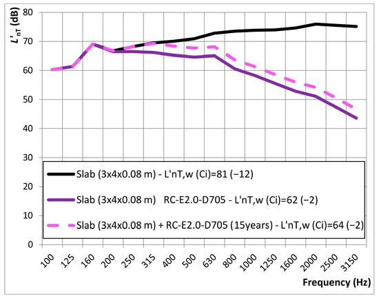
Figure 8.
Estimated L’nT of the slab system with (present and 15 years of loading) and without the RC-T2.0-D705 composition.
Considering the analyzed room and structural slab, the bare slab standardized impact sound pressure level spectrum was approximately flat and increased with frequency. The application of the RC-T2.0-D705 lightweight floating floor composition resulted in a substantial decrease, starting from the floating floor natural frequency, in the impact sound levels for all the analyzed frequency bands. Because the reduction in impact noise from the lightweight floating floor increased with frequency, its efficiency when installed over a structural slab also increased with frequency, being responsible for a reduction of nearly 31 dB at the 3.150 Hz central frequency band.
Analyzing the lightweight floating floor’s performance when submitted to the prolonged action of the usual floor loading, over 15 years, the decrease in its capacity for the reduction of impact sounds resulted in an approximate increase in the standardized impact sound pressure level of the slab system (structural slab + floating floor) of 3 dB from 315 to 3.150 Hz central frequency bands. In terms of perception, as studied by McShefferty, Whitmer and Akeroyd [33], 3 dB differences can be reliably discriminable independently of the hearing ability of the building user.
Lastly, to evaluate the overall performance rating of the hypothetical room with the reinforced concrete slab system in the application of the lightweight floating floor (present and future), Figure 9 shows the estimated weighted standardized impact sound pressure level and the achieved performance level according to the Brazilian standard.
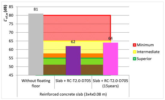
Figure 9.
Performance rating (in terms of L’nT,w) of the slab system with (present and 15 years of loading) and without the RC-T2.0-D705 composition.
Considering reinforced concrete without the use of the lightweight floating floor, its weighted standardized impact sound pressure level (81 dB) was higher than the minimum Brazilian performance level (L′nT,w ≤ 80 dB). When the RC-T2.0-D705 lightweight floating floor composition was used with the slab system, the L′nT,w dropped to 62 dB, configuring the performance level of the room to an intermediate level.
Despite all the stated and noticeable performance losses of the lightweight floating floor composition against impact sounds over prolonged loading periods (15 years), the increase of 2 dB in the weighted standardized impact sound pressure level was not enough to increase the performance level from an intermediate to a superior level according to the Brazilian standard. This means that the RC-T2.0-D705 lightweight floating floor composition has properties to endure usual residential building loads for a minimum period of 15 years, guaranteeing performance maintenance over this time.
In addition, the estimated loss of 2 dB in the impact sound insulation is relatively low, falling within the tolerance range for performance verification by in situ measurements (3 dB) [34,35,36,37,38,39]. This indicates that the predicted loss of performance may be masked by in situ measurement uncertainties and by the inherent variations in construction execution. Despite the negligible impact of the 2 dB overall performance loss of this system, a way to mitigate the acoustic loss over time is to use recycled rubber mat compositions that do not have an expected performance loss due to strain under normal representative loads, such as RC-T5.0-D860 and RC-T9.0-D875.
4. Conclusions
Appropriate impact sound insulation of the flooring systems is necessary to guarantee adequate sound levels along a building’s rooms when usual activities are performed. In this case, lightweight floating floors are efficient solutions to increase the impact sound insulation capacity of the building floor system.
Considering the lightweight floating floor composition analyzed in this research, formed from a ceramic tile rigid walking surface over a recycled rubber mat resilient layer, its initial reduction in impact sound pressure levels is adequate to promote a significant increase in performance, ranging from 16 to 18 dB in terms of the weighted reduction in impact sound pressure level among the tested compositions.
Although the present performance increases, accelerated compressive creep tests showed that the strain of the resilient material over prolonged load conditions can significantly decrease the material thickness over time. The loading effect was more pronounced in compositions with lower thickness and density, resulting in significant performance loss (reduction of 2 dB in the weighted reduction in impact sound pressure level) but less meaningful for compositions with a higher thickness and density, which maintained their performance over time.
Under the conditions analyzed, considering the lightweight floating floor with the greatest weighted reduction in impact sound pressure level loss across the 15 years period (2 dB), the performance loss against impact sounds was not enough to result in a performance level decrease, according to the Brazilian performance standard (ABNT NBR 15575-3 [32]), considering the weighted standardized impact sound pressure level.
Author Contributions
Conceptualization, methodology and investigation, B.F.T., J.P. and S.K.F.; formal analysis, investigation, data curation and writing—original draft preparation, S.K.F.; writing—review and editing, B.F.T., F.P., J.P., H.Z.E. and R.C. All authors have read and agreed to the published version of the manuscript.
Funding
This study was financed in part by the Coordenação de Aperfeiçoamento de Pessoal de Nível Superior-Brasil (CAPES)-Finance Code 001.
Data Availability Statement
This study is based on a doctoral thesis that is still under development (estimated to be published in August), so we don’t have a public data basis for this study yet.
Conflicts of Interest
The authors declare no conflict of interest.
References
- Mendis, P.; Ngo, T. Vibration and shock problems in civil engineering structures. In Vibration and Shock Handbook, 1st ed.; Taylor & Francis Group: Boca Raton, FL, USA, 2005. [Google Scholar]
- Vigran, T.E. Building Acoustics, 1st ed.; Taylos & Francis: Oxon, UK, 2008. [Google Scholar]
- Lechner, N. Plumbing, Electricity, Acoustics: Sustainable Design Methods for Architecture, 1st ed.; John Wiley & Sons Inc.: Hoboken, NJ, USA, 2012. [Google Scholar]
- Patrício, J. Acústica Nos Edifícios, 7th ed.; Quântica Editora: Porto, Portugal, 2018. [Google Scholar]
- Warnock, A.C.C.; Fasold, W. Sound insulation: Airborne and impact. In Encyclopedia of Acoustics, 1st ed.; Crocker, M.J., Ed.; John Wiley & Sons Inc.: New York, NJ, USA, 1997; pp. 1129–1160. [Google Scholar]
- Warnock, A.C.C. Controlling the Transmission of Impact Sound Through Floors; Construction Technology Update n° 35; National Research Council of Canada: Ottawa, Canada, 1999; Volume 35, 6p. [Google Scholar]
- Seddeq, H.S. Technical note: Controlling the impact sound insulation of concrete slab floors. Build. Acoust. 2006, 13, 243–251. [Google Scholar] [CrossRef]
- Hopkins, C. Sound Insulation, 1st ed.; Elsevier: Oxford, UK, 2007. [Google Scholar]
- Bies, D.A.; Hansen, C.H.; Howard, C.Q.; Hansen, K.L. Engineering Noise Control, 6th ed.; CRC Press: Boca Raton, FL, USA, 2023. [Google Scholar]
- Foreman, J.E.K. Sound Analysis and Noise Control, 1st ed.; Van Nostrand Reinhold: New York, NY, USA, 1990. [Google Scholar]
- Turner, J.D.; Pretlove, A.J. Acoustics for Engineers, 1st ed.; Macmillan Education Ltd.: Hampshire, UK, 1991. [Google Scholar]
- Mace, B. Fundamentals of vibration. In Fundamentals of Sound and Vibration, 2nd ed.; Fahy, F., Thompson, D., Eds.; CRC Press: Boca Raton, FL, USA, 2015; pp. 311–362. [Google Scholar]
- Alonso, A.; Patricio, J.; Suárez, R. On the efficiency of impact sound insulation systems on prefabricated lightweight floor and on standard homogeneous base-floor. Eng. Struct. 2019, 191, 649–657. [Google Scholar] [CrossRef]
- Cremer, L.; Heckl, M.; Petersson, B.A.T. Structure-Borne Sound, 3rd ed.; Springer: Berlin/Heidelberg, Germany, 2005. [Google Scholar]
- Nilsson, A.; Liu, B. Vibro-Acoustics; Science Press: Beijing, China, 2015; Volume I. [Google Scholar]
- Schiavi, A.; Belli, A.P.; Russo, F. Estimation of acoustical performance of floating floors from dynamic stiffness of resilient layers. Build. Acoust. 2005, 12, 99–113. [Google Scholar] [CrossRef]
- Schiavi, A.; Belli, A.P.; Corallo, M.; Russo, F. Acoustical performance characterization of resilient materials used under floating floors in dwellings. Acta Acust. United Acust. 2007, 93, 477–485. [Google Scholar]
- Caniato, M.; Bettarello, F.; Marsich, L.; Ferluga, A.; Sbaizero, O.; Schmid, C. Time-depending performance of resilient layers under floating floors. Constr. Build. Mater. 2016, 102, 226–232. [Google Scholar] [CrossRef]
- Rindel, J.H. Sound Insulation in Buildings, 1st ed.; Taylor & Francis Group: Boca Raton, FL, USA, 2018. [Google Scholar]
- Maderuelo-Sanz, R.; Martín-Castizo, M.; Vílchez-Gómez, R. The performance of resilient layers made from recycled rubber fluff for impact noise reduction. Appl. Acoust. 2011, 72, 823–828. [Google Scholar] [CrossRef]
- Db Cover (dB Cover Acoustic Protection Solutions). dB Impact: Impact Sound Insulation Product Data; DB Cover: Elda, Spain, 2018. [Google Scholar]
- Arenas, J.P.; Sepulveda, L.F. Impact sound insulation of a lightweight laminate floor resting on a thin underlayment material above a concrete slab. J. Build. Eng. 2022, 45, 103537. [Google Scholar] [CrossRef]
- García-Cobos, F.J.; Maderuelo-Sanz, R. Using different waste as resilient layers for impact sound insulation improvement: New alternative to commercial layers? Build. Serv. Eng. Res. Technol. 2022, 43, 407–417. [Google Scholar] [CrossRef]
- ISO 9052; Acoustics: Determination of Airflow Resistance: Part 1: Static Airflow Method. International Organization for Standardization (ISO): Geneva, Switzerland, 1989.
- Asdrubali, F.; D’alessandro, F. Impact sound insulation and viscoelastic properties of resilient materials made from tyre granules. Int. J. Acoust. Vib. 2011, 16, 119–125. [Google Scholar] [CrossRef]
- Schiavi, A.; Guglielmone, C.; Miglietta, P. Effect and importance of static-load on airflow resistivity determination and its consequences on dynamic stiffness. Appl. Acoust. 2011, 72, 705–710. [Google Scholar] [CrossRef]
- ISO 16534; Thermal Insulating Products for Building Applications: Determination of Compressive Creep. International Organization for Standardization (ISO): Geneva, Switzerland, 2020.
- ISO 10140; Acoustics: Laboratory Measurement of Sound Insulation of Building Elements: Part 5: Requirements for Test Facilities and Equipment. International Organization for Standardization (ISO): Geneva, Switzerland, 2021.
- ISO 717; Acoustics: Rating of Sound Insulation in Buildings and of Building Elements: Part 2: Impact Sound Insulation. International Organization FOR Standardization (ISO): Geneva, Switzerland, 2020.
- Oliveira, M.F.D.; Klippel Filho, S.; Pacheco, F.; Patrício, J.V.; Tutikian, B.F. Influence of ceramic block geometry and mortar coating on the sound reduction of walls. Ambiente Construído Porto Alegre 2021, 21, 195–207. [Google Scholar] [CrossRef]
- ISO 12354; Building Acoustics: Estimation of Acoustic Performance of Buildings from the Performance of Elements: Part 2: Impact Sound Insulation Between Rooms. International Organization for Standardization (ISO): Geneva, Switzerland, 2017.
- NBR 15575; Edificações Habitacionais: Desempenho: Parte 3: Requisites para Sistemas de Pisos. Associação Brasileira de Normas Técnicas (ABNT): Rio de Janeiro, Brazil, 2021.
- Mcshefferty, D.; Whitmer, W.M.; Akeroyd, M.A. The just-noticeable difference in speech-to-noise ratio. Trends Amplif. 2015, 19, 1–9. [Google Scholar] [CrossRef] [PubMed]
- Souza, J.; Kern, A.; Tutikian, B. Análise quantiqualitativa da norma de desempenho (NBR nº 15.575/2013) e principais desafios da implantação do nível superior em edificação residencial de multipavimentos. Gestão Tecnol. Projetos 2018, 13, 127–144. [Google Scholar] [CrossRef]
- Tutikian, B.; Zuchetto, L.; Souza, R.; Oliveira, M. Uso de agregado leve de EVA em contrapiso argamassado para isolamento ao ruído de impacto em edificações residenciais. Ambiente Construído 2017, 17, 295–306. [Google Scholar] [CrossRef]
- Rasmussen, B.; Carrascal, T.; Secchi, S. A comparative study of acoustic regulations for hospital bedrooms in selected countries in Europe. Buildings 2023, 13, 578. [Google Scholar] [CrossRef]
- Patrício, J. The Portuguese policy for building acoustics assessment. In Internoise; Internoise: New York, NY, USA, 2012. [Google Scholar]
- Christ, R.; Pacheco, F.; Ehrenbring, H.; Quinino, U.; Mancio, M.; Muñoz, Y.; Tutikian, B. Study of mechanical behavior of ultra-high performance concrete (UHPC) reinforced with hybrid fibers and with reduced cement consumption. Rev. Ing. Construcción 2019, 34, 159–168. [Google Scholar] [CrossRef]
- Murillo, M.; Abisambra, V.; Aura, P.; Quesada, Q.; Tutikian, B.; Ehrenbring, H. Comparison of the fire resistance behaviour of structural insulated panels with expanded polystyrene core treated with intumescent coating. J. Mater. Res. Technol. 2021, 12, 1958–1969. [Google Scholar] [CrossRef]


Disclaimer/Publisher’s Note: The statements, opinions and data contained in all publications are solely those of the individual author(s) and contributor(s) and not of MDPI and/or the editor(s). MDPI and/or the editor(s) disclaim responsibility for any injury to people or property resulting from any ideas, methods, instructions or products referred to in the content. |
© 2025 by the authors. Licensee MDPI, Basel, Switzerland. This article is an open access article distributed under the terms and conditions of the Creative Commons Attribution (CC BY) license (https://creativecommons.org/licenses/by/4.0/).