Article

Designing Gridshells Using Reused Members as a Sustainable Solution

1
Department of Civil and Mechanical Engineering, University of Cassino and Southern Lazio, via G. Di Biasio 43, 03043 Cassino, Italy
2
European University of Technology, European Union
*
Author to whom correspondence should be addressed.
Buildings 2025, 15(13), 2198; https://doi.org/10.3390/buildings15132198
Submission received: 21 May 2025 / Revised: 13 June 2025 / Accepted: 20 June 2025 / Published: 23 June 2025
(This article belongs to the Section Building Structures)

Abstract

The building industry is a major consumer of resources and a significant contributor to environmental degradation, largely due to its reliance on energy-intensive materials and construction practices. In this context, the reuse of components from decommissioned structures offers a promising strategy for reducing the environmental impact of new constructions. Steel products are particularly suitable for reuse, as they retain their mechanical properties over time. However, the adoption of reused members requires a shift from conventional design approaches, which typically allow for free dimensioning of elements, toward strategies where components must be selected from available stocks and strategically integrated into new structures. This process demands a careful balance between geometric configuration, structural performance, and material availability. This paper presents a new design methodology for gridshells that integrates geometry and sizing optimization to maximize the use of reused members. The proposed approach was validated through application to a dome structure. The structural behavior was assessed through nonlinear buckling analyses, alongside a simplified evaluation of greenhouse gas emissions to quantify the environmental impact. The findings highlight the potential of reuse-based strategies to promote more sustainable structural designs.

1. Introduction

The construction industry is one of the largest resource consumers, mainly due to its dependence on energy-intensive materials and building methods. Over the years, recycling has become a common practice, allowing for the transformation of waste into usable materials to reduce the environmental burden. However, recycling processes often require considerable energy for material recovery and treatment, which can limit their overall environmental advantages [1]. The sector is becoming increasingly aware of these impacts and is now turning to design strategies that focus on reducing its ecological footprint through innovative and practical solutions. Among these strategies, reuse stands out as a less energy-demanding alternative, offering significant potential to decrease environmental impacts by directly reintroducing structural components from demolished buildings into new constructions [1,2,3]. Unlike recycling, reuse bypasses energy-intensive processing, making it a more sustainable option. Recent studies have explored the integration of reused elements with new materials in structural design, highlighting their ability to reduce greenhouse gas emissions while ensuring adequate structural performance. This approach has been successfully applied across various materials, including timber [4,5], concrete [6], and steel [1,2,3,7,8,9]. Steel offers several key advantages over other construction materials from the perspective of reuse: unlike materials such as concrete or timber, the mechanical performance of steel does not significantly degrade over time, making it particularly suitable for reuse without substantial reprocessing. Further, steel components are often assembled using bolted connections that are easy to disassembly compared to cast-in-place concrete or timber constructions in which the elements are typically connected by steel joints. In addition, steel elements are generally produced according to standardized profiles, which increases their compatibility and adaptability in new designs. However, from a reuse perspective, the choice of material to reuse is not only driven by its advantages, but also by the practical availability of decommissioned structures. For this reason, it is of interest to study all material scenarios. The present study focused on steel gridshells as a relevant and technically feasible case among the different possible applications of reuse-based design [10]. Thanks to their lightweight, grid-like configuration and efficient material use, gridshells offer exceptional adaptability in terms of shape and form. Their curved geometry enables long spans with minimal material consumption, supporting sustainability goals. Although recent research has introduced advanced optimization techniques combining sizing, topology, and shape for innovative designs [11,12,13,14,15,16,17,18], there is limited research focusing on the specific challenge of integrating reused elements into the design of gridshells [8]. In this context, the present work proposes a novel gridshell design methodology that integrates geometry and sizing optimization to incorporate a defined portion of reused elements from existing inventories. The method was validated using a well-known case study—the Dome of the Freegrid Benchmark [19,20]. This approach strategically merges geometry and sizing optimizations to create gridshells that maximize the use of reused beams selected from available stocks. The methodology was tested on domes using different inventories characterized by varying quantities, lengths, and cross-sectional profiles. The main objective of this work was to develop an optimization strategy capable of minimizing the weight of a gridshell structure while simultaneously adapting the position of its nodes to accommodate a predefined set of reused elements. Once optimal configurations are obtained, they are evaluated a posteriori from both structural and environmental perspectives. Structural performance is assessed through nonlinear buckling analysis, while environmental impact is estimated using a simplified calculation of greenhouse gas (GHG) emissions based on life cycle assessment data available in the literature. These evaluations are not separate research goals but serve to support and emphasize the effectiveness of the proposed optimization approach. In particular, they demonstrate the potential of the methodology to generate structurally efficient and environmentally conscious designs.

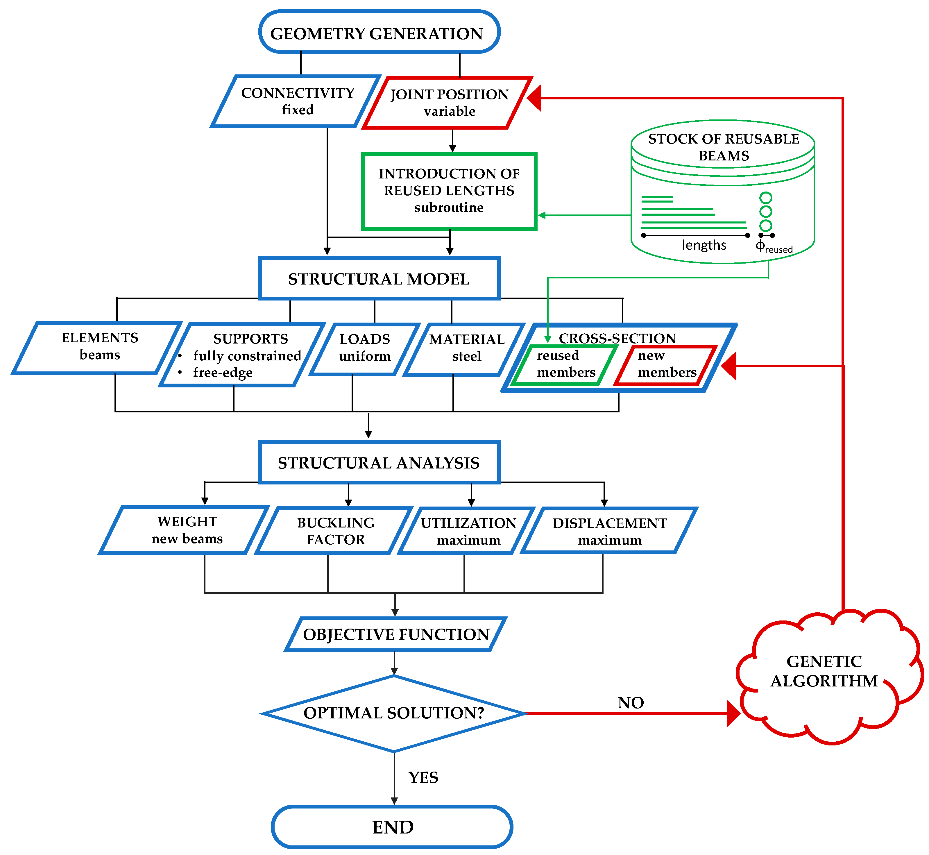
2. Proposed Design Optimization Approach

The proposed design optimization approach combines geometry and sizing optimization for the minimum-weight design of gridshells using a mix of new and reused components, as outlined in the flowchart in Figure 1. In general, the method seeks the lightest gridshell configuration by simultaneously modifying joint coordinates and the cross-section of new members, while inserting the maximum possible number of reused components from a predefined stock of members. The algorithm works on a parametric geometric model where the shape and the connectivity between elements is fixed, but the joint positions are variables in the optimization problem. For each generated configuration, a subroutine compares each member’s length against the length of reusable beams within the stock, and the joints are slightly moved (by elongating or shortening the actual members), in order to reach the desired length of the reusable beams. Once the geometry and the position of the reusable beams are defined, a structural model is generated: members matching the stock lengths receive their corresponding cross-sections (“reused beams”), while the section sizes of all the other members (“new beams”) are optimization variables. Material properties, loads, and supports are then input. The model is subjected to linear static and linear buckling analyses to determine the weight of the new beams, buckling factor (BF), maximum utilization ratio (Umax) (demand versus capacity), and maximum displacement (Dmax). These metrics feed into the objective function, defined as the sum of the new beams’ weight plus penalty terms for buckling, utilization, and displacement to ensure that the stiffness and strength requirements are met. If this solution is optimal, the algorithm stops and returns the design. Otherwise, the current objective value guides the genetic algorithm in iteratively varying the joint positions and cross-sections of new beams to improve the solution. The following sections will describe in detail the parametric geometry, the structural modeling and analysis, and the optimization process. All phases of the workflow have been developed in the Grasshopper environment [19] using Karamba3D [20] for finite element analyses. Grasshopper [19], one of the most popular and advanced algorithmic modeling tool, is a plug-in for Rhinoceros [21] that was developed by David Rutten at Robert McNeel & Associates. It is a platform that allows designers to plug and unplug different functions depending on the specific design context, and works as a graphical associative logic modeler and algorithm editor. Karamba3D [20] is a Grasshopper plug-in; it is a finite element analysis code that is geared towards interactive use in Grasshopper parametric environments. The genetic algorithm employed was Galapagos [22], a specific algorithm that is implemented in Grasshopper.

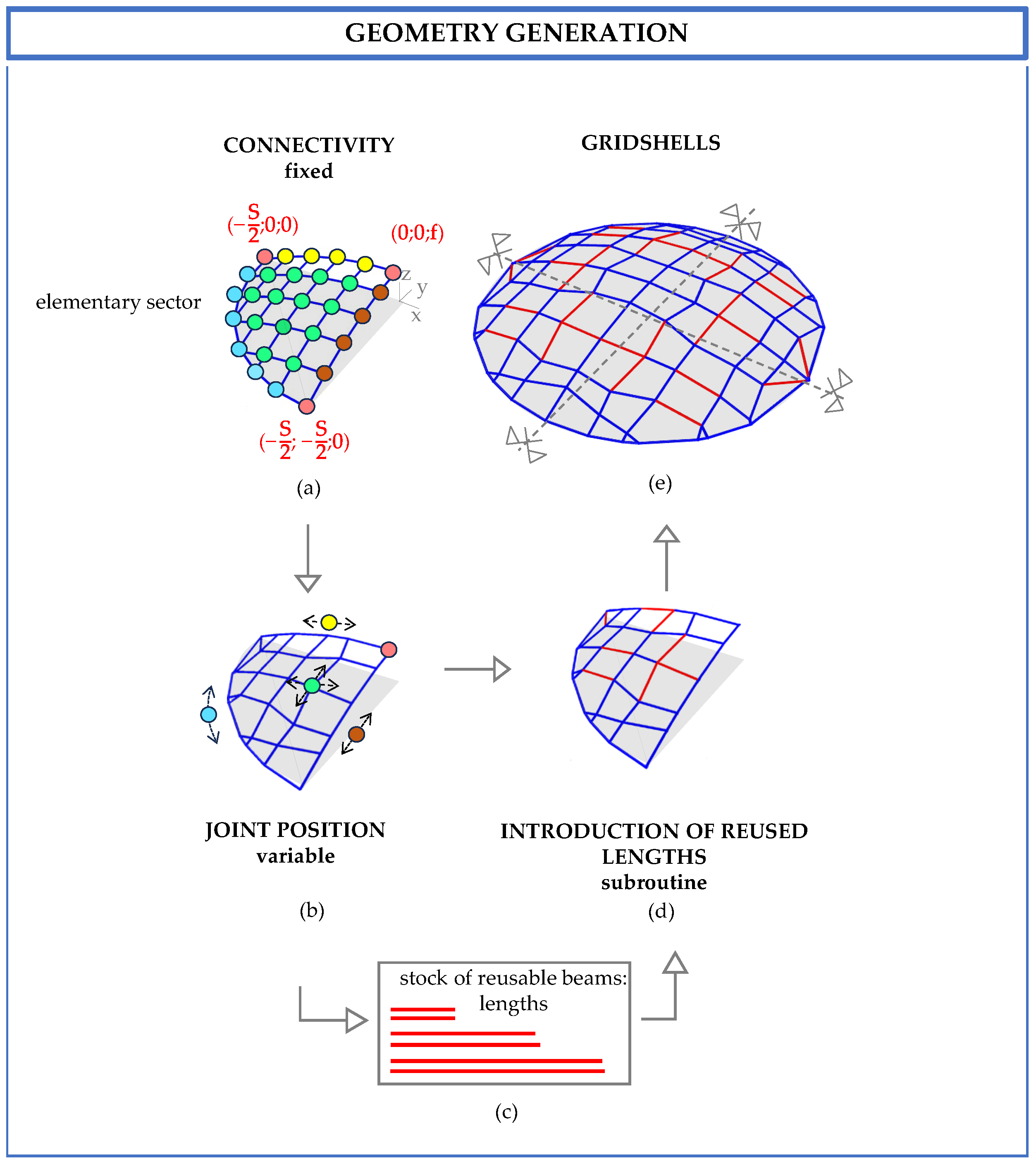
2.1. Definition of the Parametric Geometrical Model

The main steps of the geometry generation process are shown in Figure 2 using a double-symmetric gridshell dome as an example, but the method can be extended to accommodate any double-symmetric geometry. The generation process starts from the elementary sector (Figure 2a), which is mirrored four times to obtain the entire geometry (Figure 2e). This elementary sector is realized by moving the positions of joints along a predefined surface, starting from an initial gridshell based on a regular square mesh discretization (Figure 2a). The geometric variables of the algorithm are the controlled movements of the joints that modify the grid (Figure 2a), which are constrained to move within a predefined range of values. In general, the variables are the x- and y-coordinates of the joints that could vary in the range of amin–amax, while the z-coordinate is constrained to the predefined double-symmetric surface. Due to the dome’s curved perimeter and its double symmetry, specific displacement constraints are imposed on the boundary and corner joints to ensure that both the symmetry and the footprint of the dome are not modified:
-
Joints along the internal boundary parallel to the x-axis (highlighted in yellow in Figure 2a,b) are only allowed to move along the x-direction, and the z-coordinate is evaluated to ensure that it belongs to the generatrix (also see Section 3):
x   0 , j + a min <   x   1 , j   <   x   0 , j + a max
z   1 , j = x 1 , j 2 2 B + f
where x0,j is the initial x-coordinate of the j-th joint, x1,j is the final x-coordinate, and z1,j is the final z-coordinate.
-
Joints along the internal boundary parallel to the y-axis (brown joints in Figure 2a,b) are only allowed to move along the y-direction, and the z-coordinate is evaluated to ensure that it belongs to the directrix (also see Section 3):
y 0 , j + a min <   y 1 , j <   y 0 , j + a max
z   1 , j = y 1 , j 2 2 B + f
where y0,j is the initial position of the i-th joint and x1,j is the final position.
-
Corner joints (pink joints in Figure 2a,b) remain fixed:
x   1 , j =   x   0 , j ;   y   1 , j = y   0 , j ;   z   1 , j = z   0 , j
-
Joints along the perimeter (cyan joints in Figure 2a,b) are only allowed to move along the curvilinear boundary. Since, in this study, the boundary is defined by a circle, the new x-coordinate is a variable, while the new y-coordinate is evaluated to ensure that it belongs to the circular perimeters, and the z-coordinate is zero:
x   0 , j + a min <   x   1 , j <   x   0 , j + a max
y   1 , j = S 2 2 x   1 , j 2
z   1 , j = 0
where S is the diameter of the perimeter circle and f is the rise of the surface (Figure 2a).
-
Internal joints (green joints in Figure 2a,b) are free to move in both the x- and y-directions.
After the geometry is defined, an ad hoc subroutine identifies which lines within the adjusted grid closely match the lengths of reusable beams available in the stock (highlighted in green in Figure 2c). The joints at the ends of these lines are slightly modified to align their lengths with those of the selected reused beams (Figure 2d) following a specific set of rules:
  • The starting joint of a selected line is moved to either extend or shorten the beams until its length matches the corresponding reused beam.
Specifically, the j-th line of the elementary sector of the gridshell is considered, which is defined by the starting joint P1,j and the final joint P2,j with initial coordinates of
P 1 , j = ( x 1 , j ,   y 1 , j ,   z 1 , j ) ;   P 2 , j = ( x 2 , j ,   y 2 , j ,   z 2 , j )
The original length of the line is computed as follows:
L o , j = [ ( x 2 , j x 1 , j ) 2 + ( y 2 , j y 1 , j ) 2 + ( z 2 , j z 1 , j ) 2 ]
Given a reused beam with target length Lr, the objective is to modify the starting joint (i.e., P1,j) such that the new element length is exactly equal to Lr.
Thus, the direction cosines of the original element are evaluated as
Δ x , j = x 2 , j x 1 , j ;   Δ y , j = y 2 , j y 1 , j ;   Δ z , j = z 2 , j z , 1
The unit direction vector dⱼ can be written in scalar form as
d x , j = Δ x , j / L e , j ;   d y , j = Δ y j / L e , j ;   d z , j = Δ z j / L e , j
Then, the modified coordinates (x1ⱼ′, y1ⱼ′, z1ⱼ′) of the new starting P1ⱼ′ are given by
x 1 , j = x 1 , j + ( L r / L e , j ) ( x 2 , j x 1 , j ) ;   y 1 , j = y 1 , j + ( L r / L e , j ) ( y 2 , j y 1 , j ) ;   z 1 , j = z 1 , j + ( L r / L e , j ) ( z 2 , j z 1 j , )
This formula ensures that the geometry of the element is preserved in terms of direction, while its length is adjusted to exactly match that of the available reused member.
2.
If the selected joint is the starting point of more than one selected line, the movement is applied to the opposite (end) joint. The formula is the same as the one described for the previous point, but is used for the movement of the end joint.
3.
If the joint to be moved lies along a symmetry axis, its movement is allowed along the symmetry axis and in the z-direction in order to achieve the target length.
Specifically, considering the j-th line of the elementary sector of the gridshell, which is defined by the starting joint P1,j and the final joint P2,j (defined in Equation (9)), it is possible to distinguish two cases: the x-axis is the symmetry axis and movement is only allowed along the x- and z-axes, while the y-coordinate remains fixed or the y-axis is the symmetry axis and movement is only allowed along the y- and z-axes, while the x-coordinate remains fixed. In the first case, x 2 , j is a variable, y 2 , j is fixed, and z 2 , j is defined as
z 2 , j = z 1 , j + ( L r / L e , j ) ( z 2 , j z 1 , j )
In the second case, y 2 , j is a variable, x 2 , j is fixed, and z 2 , j is calculated using Equation (14).
4.
If the joint lies along the curved perimeter of the elementary sector, its movement is constrained to this curve.
In this case, the coordinates of the updated point P2,j can be defined as a function of the angular parameter θ:
x 2 , j = r   · cos θ ; y 2 , j = r   · sin θ ; z 2 , j = 0
where r is the radius of the arc of the circle that defines the curved perimeter.
By making the distance between points P2,j and P1,j equal to the desired length Lr, θ is equal to
θ = sin 1 C x 1 , j 2 + y 1 , j 2 tan 1 2 y 1 , j , x 1 , j   ; C = r 2 + x 1 , j 2 + y 1 , j 2 + z 1 , j 2 L r 2 2 r
Once this procedure is completed, the actual geometry of the elementary sector (Figure 2d) is mirrored along the symmetry axes to realize the full gridshell structure with double symmetry, as shown in Figure 2a.
In the proposed method, the gridshell geometry is first generated for a single elementary sector and then replicated and mirrored through symmetry operations to generate the complete structure. To ensure consistency with the available stock of reclaimed members, the number of reused elements allocated within the elementary sector is defined in such a way that their symmetric counterparts can also be matched. Specifically, each element selected for reuse in the elementary sector is assumed to be available in sufficient quantity—typically four times its count—so that it can be mirrored along both axes of symmetry. This approach guarantees that the final design remains compatible with the initial stock definition.

2.2. Definition of the Structural Models and Structural Analyses

After generating the geometry definition, the structural model of the gridshell has to be developed. The reused beams from the stock are assigned to their corresponding cross-section and their material properties are added to the model. The cross-section of the new beams is a variable in the optimization process. In the present study, the cross-sections were assumed to be pipes (hollow circular sections) and the diameter of these pipes (ϕnew) was an optimization variable. The wall thickness (tnew) was a function of ϕnew, and the diameters (ϕreused) and thicknesses (treused) of the reused beams in the stock were used. All structural members were modeled as beams and assuming fixed connections at all joints. Loads derived from an equivalent distributed load were applied as concentrated forces at the structural joints. The support conditions included external hinges along the perimeter of the gridshell.
The structural model was then analyzed using linear static and linear buckling analyses, which provided the necessary information to evaluate the objective function, which depends on the structural weight of the new members (Wnew) and on structural constraints imposed on the linear buckling factor (BF), defined as the ratio between the critical buckling load and the applied load, the ratio between the maximum displacement Dmax and the displacement limit Dlim (Δ), and the maximum utilization ratio (Umax). The linear buckling factor (BF) should be larger than 1 to ensure stability; the maximum displacement ratio (Δ) should be smaller than one, where the allowable displacement limit Dlim is B/250; the maximum utilization ratio Umax, defined as the demand-to-capacity ratio, should be smaller than one [23].

2.3. Optimization Process

The goal of the optimization process is to determine the gridshell topology that minimizes the weight of the new structural members by combining reused beams and new ones, whose cross-section is a variable in the optimization process. Since the weight of the new members is influenced by both their quantity and their cross-sectional size, the algorithm aims to promote the use of reused beams while reducing the dimensions of the new ones as much as possible. This process is governed by constraint conditions for displacement, buckling factors, and the utilization ratio, as explained in Section 2.2, which must all be met to ensure the structural admissibility of the final solution. The optimization problem is defined as follows:
M i n i m i z e W n e w C o n s t r a i n t s U m a x     1 B F     1 Δ     1 V a r i a b l e s ϕ n e w j o i n t   m o v e m e n t s   a l o n g   x-   a n d   y- a x e s
It is treated as a constrained optimization problem by the mono-objective genetic algorithms. As is common in constrained optimization, the problem was reformulated as an unconstrained problem by introducing penalty functions in the objective function [24,25]. Then, the objective function was defined as follows:
O F = W n e w + j = 1 3 α j · c j
where
c j = 1   i f   c o n s t r a i n t   j   i s   v i o l a t e d c j = 0   i f   c o n s t r a i n t   j   i s   s a t i s f i e d
where j represents the j-th constraint and αj is the penalty factor associated with the violation of the j-th constraint. The penalty factors (αj) are chosen to be large compared to the weight of new beams (Wnew) to ensure that the optimization algorithm excludes non-admissible solutions. In this specific problem, the penalty functions (cj) are defined as follows:
c 1 = 1   i f   U m a x > 1   c 1 = 0   i f   U m a x 1   c 2 = 1   i f   B F 1   c 2 = 0   i f   B F > 1   c 3 = 1   i f   Δ > 1   c 3 = 0   i f   Δ 1  
The values of α1, α2, and α3 were set equal to 103 in order to be one order of magnitude larger than the weight (in kN) of the reference solution designed with new beams through a sizing optimization approach, i.e., the base case.
In the case where the available stock of reused elements, in combination with new elements, is not able to satisfy the design requirements, the algorithms exclude the solutions with reused components and provide a solution with all new beams as the output. In fact, the solutions that are not able to satisfy the strength, deformability, and stability constraints are discarded from the optimization process and, at this point, a solution with all new components is selected.
The optimization algorithm employed was Galapagos [22], which belongs to the category of genetic algorithms based on natural selection. In the search for the optimal solutions, the algorithms start from the generation of a population of random solution (individuals); then, at each step, the algorithm selects individuals to be parents and uses them to generate children, i.e., individuals in the next generation. Over successive generations, the population evolves toward the optimal solution. In order to create the successive generations, Galapagos adopts three genetic operators: selection, crossover, and mutation. Specifically, the main steps of the Galapagos algorithm are as follows:
-
Creation of the first generation with random individuals (with the number of individuals set by the parameters Population·Initial Boost);
-
Computation of the OF for each individual of the current generation;
-
Selection of the best individuals in the current generation in order to generate the successive one based on survival (percentage of best individuals, set by the parameter Maintain) and through mating (creation of children);
-
Creation of children by coupling (based on the genetic distance and governed by the parameter Inbreeding Factor);
-
Definition of the random genetic changes in the parents’ genome in order to increase the bio-diversity in the population (controlled by the parameter Mutation).
The process stops when no progress is made for a specified number of generations (Max Stagnant). The values for the parameters that were set in Galapagos in this work are reported in Table 1.

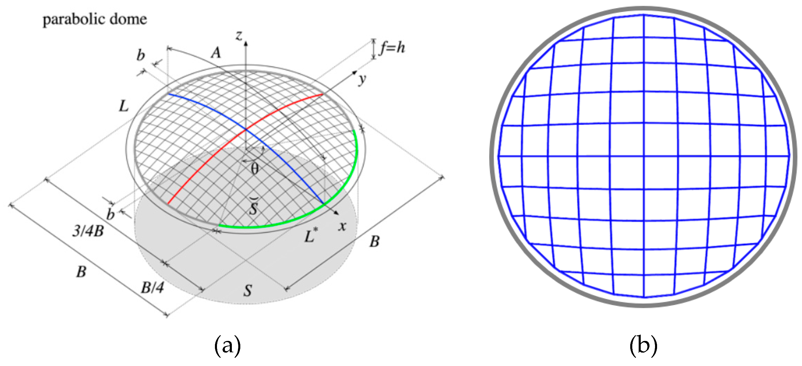
3. Description of the Case Study and Numerical Applications

The proposed approach was applied to the dome gridshell proposed in the Freegrid benchmark [26,27], which is shown in Figure 3a. The dome configuration is characterized by a parabolic generatrix (in blue) and a parabolic directrix (in red) with the following equation:
z = x 2 2 B + f
where
B 2 x B 2
A = B 5 4 + l n 1 + 5 2
where B = 30 m is the generatrix span and f = B/8 is the rise of the relevant generatrix.
The dome gridshell was subjected to a vertical uniformed distributed load of 1800 N/mm2 at the Ultimate Limit State (ULS), and to a vertical uniformed distributed load of 1200 N/mm2 at the Service Limit State (SLS), which were applied as concentrated forces to each joint of the grid in order to apply the symmetric load condition proposed by Freegrid [26,27]. The analyses at the ULS were used to check the solutions in terms of the maximum utilization ratio (Umax) and buckling factor (BF), while the analyses at the SLS were used to check the displacement ratio (Δ). A 10 × 10 square element mesh discretization was considered (Figure 3b) in lieu of the 20 × 20 (Figure 3a) mesh proposed by Freegrid [26,27] in order to reduce the computational effort. All beams were considered to have a pipe cross-section made of S355 steel with a constant diameter-to-thickness ratio of 10. The cross-section assigned to the initial grid, before optimization, had a diameter ϕ = 101, as proposed by Freegrid [26,27].
The optimization process was applied to a dome gridshell considering several stocks of reusable beams, with varying numbers (N) and lengths (L), to be introduced into the elementary sector of the gridshell (the reused beams were double mirrored to define the whole gridshell). The following five stocks were considered:
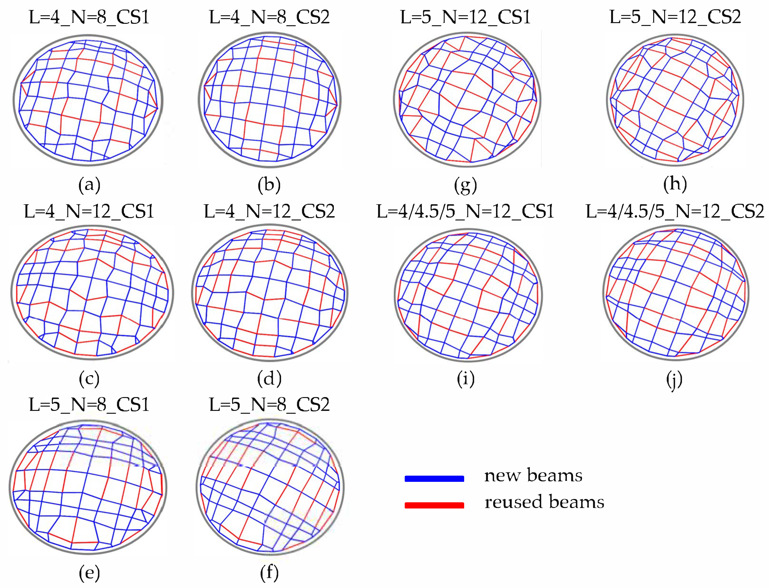
  • Stock (a): N = 8, L = 4 m;
  • Stock (b): N = 12, L = 4 m;
  • Stock (c): N = 8, L = 5 m;
  • Stock (d): N = 12, L = 5 m;
  • Stock (e): N = 12, L = 4 m (4 elements); L = 4.5 m (4 elements); L = 5 m (4 elements).
It is important to note that the first four stocks contain beams with identical lengths, while the fifth one includes members with different length values. Considering these defined stocks, two sets of analyses were conducted. In one case (CS1), all the reused beams were assumed to have the same pipe cross-section dimensions: diameter ϕreused = 101 mm and thickness treused = ϕreused/10. In the second case (CS2), the reused beams were assumed to have twice the diameter and thickness as those in CS1, and the same diameter-to-thickness ratio. Although the selection of the stock characteristics does not directly take uncertainty into account, it allowed the design to adapt to known inventories, including heterogeneous combinations of member lengths and cross-sections. Future development of the method could incorporate variable stock characteristics through probabilistic modeling of the stock parameters in order to improve the applicability of the approach in uncertain reuse scenarios. From this perspective, future studies could also explore the influence of cross-sectional shapes and material classes on the design outcomes.
According to the Freegrid benchmark, the joints are considered rigid, and this condition applies to both reused and new beams. Nevertheless, while new beams can be engineered to establish rigid connections, reused beams could necessitate alternative connection methodologies due to the varying geometries (lengths, cross-section dimensions, and shapes) of the reused members composing the stocks. In this case, semi-rigid or pinned connections could be a more practical solution than rigid ones. This aspect was not specifically considered in this study, but could certainly be an interesting aspect to study in future works. In this study, the selected reusable elements represent a theoretical stock that does not reflect real-word dismantled buildings. However, the lengths were based on values frequently encountered in structural steel elements dismantled from industrial or commercial buildings; the work did not simulate a specific dismantled structure and the aim was to represent plausible stock conditions [28]. The reclaimed steel members were assumed to belong to Class A, according to the classification framework provided by the European Recommendations for Reuse of Steel Products in Single-Storey Buildings [28]. This assumption implies that reused elements are supported by original material certification and that they meet the requirements for structural use under EN 1993 [29] without the need for extensive additional testing. In real-world applications, however, such assumptions must be rigorously validated. If the original certification is not available, reclaimed steel must undergo an adequacy assessment, which potentially involves a combination of destructive and non-destructive testing methods, such as tensile tests, dimensional surveys, and impact toughness tests. Depending on the results, the steel may be classified as Class B or Class C, which restricts its structural use. This assessment is essential to ensuring that the reused elements meet the mechanical performance criteria used in the design phase, particularly in terms of yield strength, ductility weldability, and dimensional tolerances.

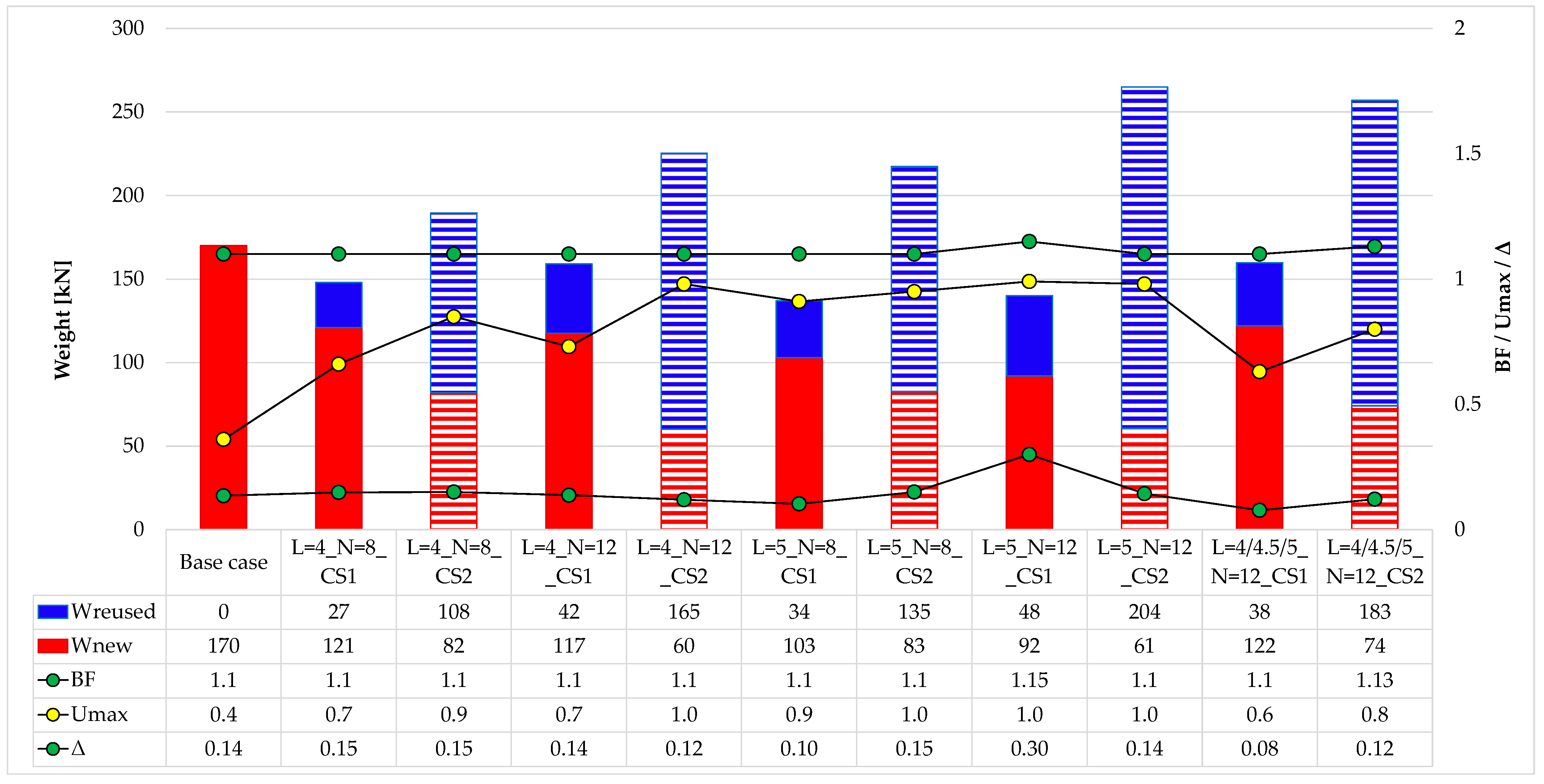
4. Results and Comments

The results in terms of topology and arrangement of new and reused beams are shown in Figure 4, where each solution is labeled as L=l_N=n_CSi, where l is the length of the beams of the actual stock, n is the number of beams (to be replaced in the elementary sector of the gridshell), and i is equal to 1 for CS1 or equal to 2 for CS2. The geometry and position of reused beams were quite similar for the two different cross-section dimensions for the reused beams, while the joint positions (geometry) differed with the different stocks. Figure 5 shows the results for the weight of new beams (Wnew), weight of reused beams (Wreused), buckling factor (BF), maximum utilization ratio (Umax), and maximum displacement ratio (Δ). Further, a reference solution named base case is presented, for the sake of comparison, for the regular gridshells shown in Figure 3b,c, which was designed with all new beams through a simple sizing optimization process (Equations (1)–(4)) by only using the diameter of new beams (ϕnew) as the variable. The results for the base case, i.e., the regular gridshell designed with all new beams, are reported in absolute terms. The solution of the base case design was governed by the buckling rather than strength, and led to a utilization ratio less than 1, as opposed to a buckling factor slightly greater than 1, i.e., the limit value. The results presented in Figure 5 show that all the solutions using the CS1 stocks, which are characterized by smaller cross-sections, achieved a lower total weight compared to the base case, with the percentage of reused beams ranging between 18% and 34%. The weight reduction varied from 6% (L=4_N=12_CS1) to 19% (L=5_N=8_CS1), highlighting the influence of the beam length on the design solution. In this specific case, the stock with lengths of 5 m offered a better fit than the 4 m ones. Moreover, it was evident that increasing the number of reused beams tended to also increase the total structural weight. On the other hand, the solutions obtained using the CS2 stocks—characterized by larger cross-sections—resulted in higher total weights than the base case, with the increases ranging between 12% and 56%. These configurations also exhibited a higher Wreused relative to the total, which ranged from 57% to 77%. Nonetheless, despite the significant percentages of reused beams, the CS2 solutions were less advantageous in terms of total weight compared to those obtained with CS1. This outcome clearly indicates that the structural efficiency of the design is highly dependent on the available beam lengths and even more on their cross-sectional dimensions. The results also suggests that one of the main constraints affecting the final configurations is the buckling factor (BF), which approached but remained slightly above the limit value of 1. In some cases, the maximum utilization ratio (Umax) was also close to its limit of 1, demonstrating that the solutions were predominately influenced by both strength and stability criteria. However, in general, the structural behavior of the gridshells was primarily governed by buckling. Conversely, the displacement ratio (Δ) was always below the limit value of 1, confirming the inherent stiffness provided by the double curvature of the gridshells. In conclusions, the results demonstrate that the proposed methodology did not results in a compromised structural performance as long as the reuse strategy was well integrated into the design process.

5. Discussion

In order to more deeply investigate the findings of the proposed optimization process and offer further insight into the effectiveness of reuse-based design strategies, additional investigations were performed. While the linear buckling and sizing evaluations provided valuable information regarding structural performance and material efficiency, they may not fully capture the complex behavior of gridshells under realistic loading conditions, nor accurately reflect the environmental benefits resulting from the integration of reused members. For this reason, and to further validate the robustness of the proposed approach, the results of the geometric nonlinear analyses (GNAs) were used to more comprehensively evaluate the buckling factor. Moreover, in order to assess the obtained solutions in terms of environmental impact, an estimation of greenhouse gas (GHG) emissions was performed. These additional investigations allowed for a more comprehensive validation of the structural feasibility and environmental advantages from using the proposed methodology.

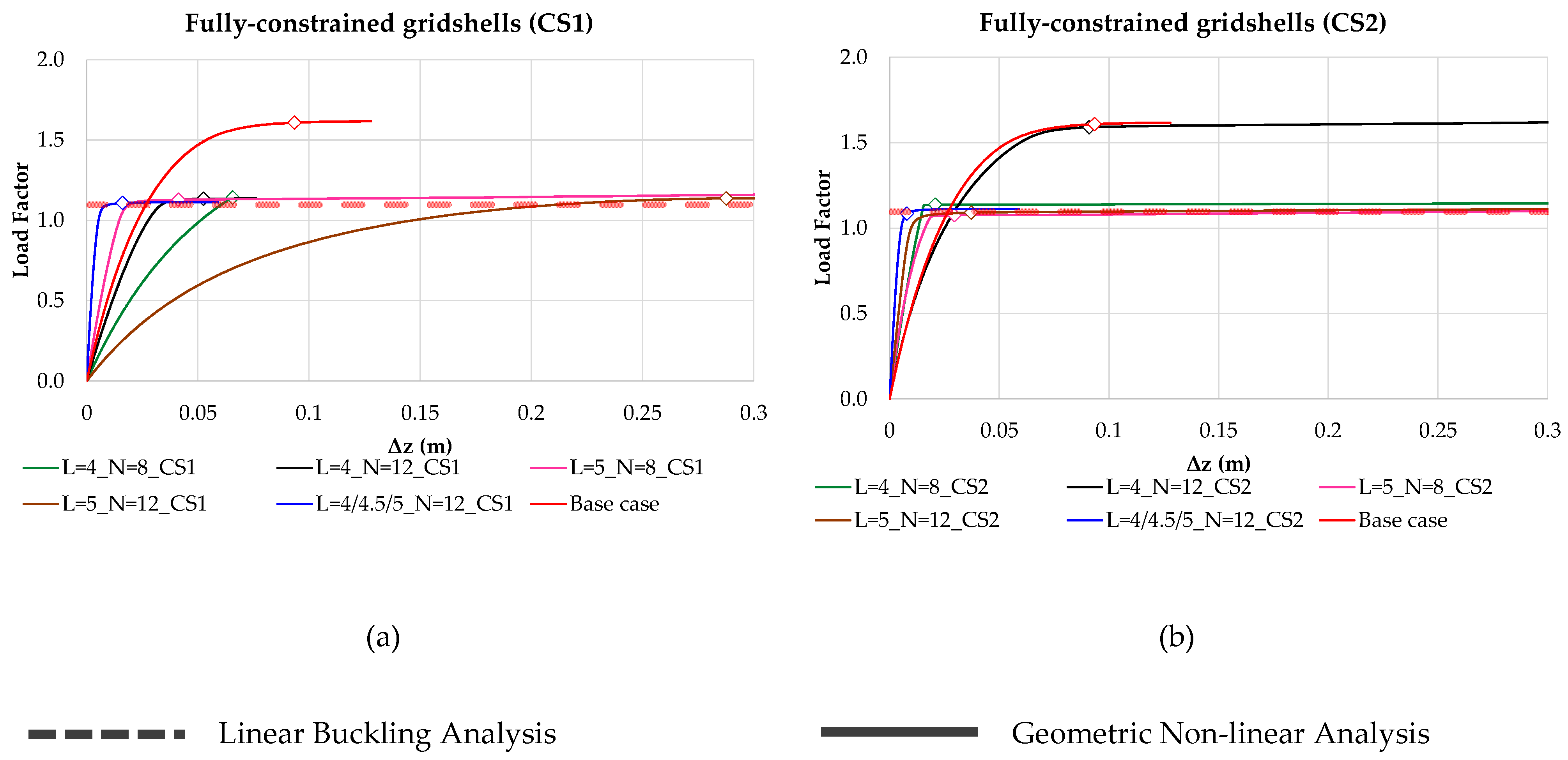
5.1. Non-Linear Static Analysis

Gridshells are structurally efficient structures that often derive their strength from their geometric configuration and in-plane force distribution. Nevertheless, due to their intrinsic slenderness and shape, their buckling behavior cannot always be accurately predicted by linear buckling analyses [30]. Indeed, the linear buckling factor (BF), derived from eigenvalue analysis, only offers a simplified estimation of the critical load that is based on a linearized model that overlooks the actual load-path and deformation behaviors. Consequently, this type of model may not provide a realistic assessment of the gridshell buckling factor. To address this limitation, geometric nonlinear analyses (GNAs) are often required since they can simulate the progressive application of a load while continuously updating the geometry of the structure. Although more computationally demanding, this analysis provides a more reliable prediction of the buckling response. This approach is also suggested by design standards like EN 1993-1-6 [29], which recommends GNAs for slender structures susceptible to buckling phenomena. GNAs were carried out on all the solutions derived from the proposed approach (Figure 6). Due to the complexity of this type of analysis, the Abaqus v.2025 software [31] was employed. In order to facilitate the integration of the optimized geometrical layouts into the numerical model, a custom Python v3.14 interface was developed. This automated the entire modeling process, enabling the direct transformation of the data from the optimization phase to the ABAQUS input format. The routine read the geometrical, structural, loading, and boundary condition data and generated the corresponding input files. This ensured a consistent implementation of the geometry, material properties, boundary conditions, and loads across all the case studies. The gridshells were discretized using 3D Timoshenko beam elements, specifically the B31 element type in ABAQUS [31]. These elements are two-node linear beam elements capable of capturing both bending and shear deformations. All members were modeled as fully fixed beams to reflect the intended structural behavior. For each case study, two material sections were defined: one for reused elements and one for new elements. These elements were characterized by their mechanical and geometrical properties during the optimization phase. The support conditions and load application were consistent with the description given in Section 3. The nonlinear analyses were developed using a load-controlled incremental scheme, which applied the load in 1000 incremental steps. The Newton–Raphson method was used to iteratively solve the equilibrium equations, with the convergence checked using a weighted residual norm tolerance of 5 × 10⁻³.
The results are presented in terms of load factor–vertical displacement (Δz) curves, where the load factor is the ratio between the actual load step and the loads to which the gridshell was subjected to. The load factor was assumed to correspond to the buckling factor (BF) when a limit point is reached (zero tangent stiffness) or when an inflection point is reach, which indicates the entry into a post-buckling regime with a different deformation mode [32]. These points are indicated in the plots with a rhomboidal indicator. The obtained results underline that all the solutions (Figure 6), which were all characterized by a linear buckling factor of about 1.1, also showed a similar or larger value for the non-linear buckling factor, meaning that these values are also admissible if the designed was based on a linear buckling analysis. This result was due to the fact that the condition of the fully constrained boundary provided an adequate level of stability to the structure. These results further confirmed the validity of the proposed approach in the optimal design of gridshells.

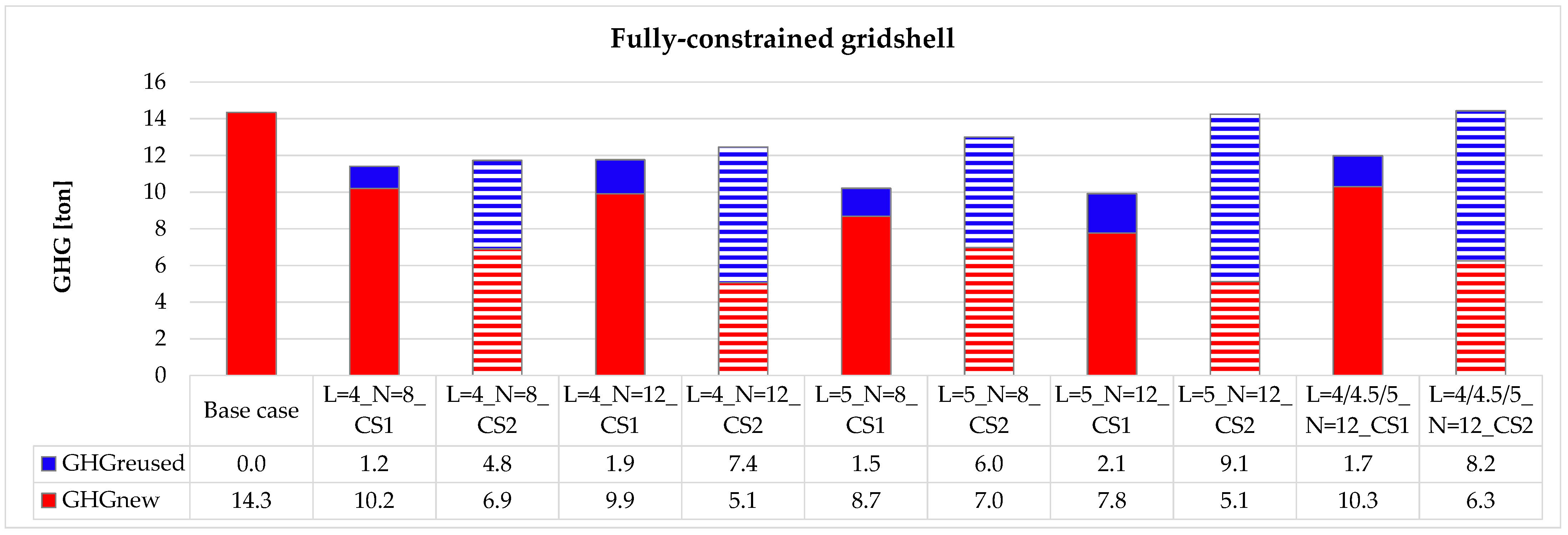
5.2. Evaluation of GHG Emissions

The main advantages of incorporating reused components are the reductions in both the overall weight and the number of newly manufactured beams, which can significantly lower construction costs. Beyond economic considerations, a key benefit of design solutions that include reused elements is their potential to mitigate environmental impacts. However, quantifying such an impact remains a complex task as it involves a variety of factors that are often difficult to measure accurately. In this context, the existing literature [1,33] suggests estimating carbon emissions generated throughout the construction process, including from the dismantling of decommissioned structures, transportation and production of new components, and the on-site assembly of all parts. These emissions are typically expressed in terms of greenhouse gas (GHG) emissions. Brütting et al. [1] proposed a simplified formula based on GHG emissions by combining information reported in [33], as well as the data from [34] and the Swiss Federal LCA database [35]. The proposed formula evaluates emissions as a function of the mass of the reused components, the mass of newly produced components, and—although not considered in this study—the quantity of construction waste.
GHG = 0.447   kgCO 2   kg · M reused + 0.844   kgCO 2   kg · M new
where Mreused and Mnew are the masses of the reused and new members, respe)ctively, in kilograms. The coefficients employed in Equation (8) were derived by summing the parameters associated with specific life cycle stages as suggested by Brütting et al. [1]. Specifically:
-
The 0.447 kgCO2/kg coefficient for reused beams includes:
Deconstruction: 0.337 kgCO2/kg;
Assembly on site: 0.110 kgCO2/kg.
-
The 0.844 kgCO2/kg coefficient for new beams includes:
Production of new steel: 0.734 kgCO2/kg;
Assembly on site: 0.110 kgCO2/kg.
Other emissions listed in Brütting et al. [1], such as those from transportation and waste handling, were excluded from the formula for the following reasons:
-
transportation emissions: these emissions were not considered since the relative distances between the structure to be dismantled and the new structure were not defined in this work;
-
waste transport and handling: these terms were omitted under the assumption that the reclaimed elements were reused at full length, so no cut-off waste was generated.
The aim of this formula is to enable a simple comparison between constructions with all new components and a combination of new and reused ones, in order to perform a preliminary assessment of the environmental impact to inform early-stage design decisions. However, this approach does not represent a complete Life Cycle Assessment (LCA), but it is intended as a preliminary approximation suitable for early-stage design comparisons, and not as a substitute for a comprehensive LCA.
Figure 7 presents the results obtained from Equation (8) for all the obtained gridshells, including the base case that was designed with all new beams. The results show that two cases with reused beams with the CS2 cross-section dimensions, i.e., L=5_N=12 and L=4/4.5/5_N=12, produced the same amounts of GHG emissions as the base case, while all the other solutions produced lower amounts. This result emphasizes how crucial the stock selection is in obtaining improved solutions and in terms of environmental footprint. It suggests that the incorporation of reused beams does not ensure a lower environmental impact compared to using entirely new beams. Thus, the proposed method could also be applied to hypothetical element stocks with the aim of identifying the necessary characteristics—such as cross-sectional dimensions and lengths—that a real stock should have to support designs that are optimized for both weight and environmental impact.

6. Conclusions

This study presents an innovative design approach for the optimization of gridshell structures by using reusable structural components from dismantled structures as stocks with predefined lengths and cross-sections. The method combines geometry and sizing optimization, using a genetic algorithm, to reduce the weight of newly introduced components while ensuring good structural performance and environmentally friendly designs. The approach was validated through application to a dome gridshell under multiple design scenarios while considering variations in stock characteristics. The key findings included the identification of how stock properties, particularly cross-section and length, affects structural efficiency, the determination of the buckling performance (through both linear and nonlinear analyses), and a comparative assessment of greenhouse gas emissions that highlighted the environmental benefits of reuse-based strategies. These results confirmed the effectiveness of the proposed method in producing structurally efficient and environmentally conscious design solutions, and its relevance to automation in sustainable construction practices. Particular attention was devoted to the risk of global buckling given its critical role in gridshell stability. The collapse of structures such as the Bucharest Dome [36] highlights the need for nonlinear verification tools to ensure safety. The structural configurations obtained through the optimization process were therefore rigorously assessed through nonlinear geometric analyses to capture potential buckling phenomena. Overall, the proposed framework is a promising approach for integrating structural optimization and circular design principles into the development of sustainable structures.
It is important to highlight that the present study only investigated gridshells with fully constrained boundary conditions. However, this conditions does not fully reflect the variety of support conditions observed in real-world applications, where edges could be partially constrained or even free. These conditions can significantly affect the mechanical behavior of the structure and the integration of reused elements. Therefore, future work could focus on extending the framework to accommodate different types of boundary conditions, such as gridshells with free edges, to increase the applicability of the approach to different and more realistic design scenarios.
The proposed methodology was specifically developed for gridshell structures; nevertheless, it can be extended and generalized to other structural typologies. Potential extensions could include planar trusses or frame buildings, where the reuse of existing elements could be integrated into parametric design workflows. Such adaptations only require adaptation of the geometry generation process.
In terms of real-world applications, one possible direction is integrating the optimization framework into Building Information Modeling (BIM) platforms. The parametric definition of the method, developed within the Grasshopper environment, is compatible with BIM-based processes, allowing for the direct exchange of geometric and structural data [37]. This integration could facilitate the early-stage exploration of reuse strategies by practitioners within coordinated digital workflows.
Nevertheless, the real-world adoption of reuse-based optimization approaches could encounter some practical challenges. One of the main barriers is the lack of centralized and standardized databases for reclaimed structural elements, which could be essential for defining realistic and reliable stocks. Furthermore, the quality control of reused members remains a critical issue, particularly in terms of verifying the mechanical properties, geometric tolerances, and compliance with current standards. While the current study classified the reclaimed steel as Class A, in practice, many reclaimed elements may require additional testing [28]. These steps highlight the necessity for a closer collaboration between designers, demolition contractors, and material recovery facilities, as well as the development of digital tools for stock cataloguing, classification, and tracing.

Author Contributions

Conceptualization, V.T., E.G. and M.I.; methodology, V.T., E.G. and M.I.; software, V.T. and M.S.; validation, V.T., M.S., E.G. and M.I.; formal analysis, V.T. and M.S.; investigation, V.T., M.S., E.G. and M.I.; resources, M.I.; data curation, V.T. and M.S.; writing—original draft preparation, V.T. and E.G.; writing—review and editing, V.T., E.G. and M.I.; visualization, V.T. and M.S.; supervision, E.G. and M.I.; project administration, M.I.; funding acquisition, M.I. All authors have read and agreed to the published version of the manuscript.

Funding

Project ECS 0000024 “Ecosistema dell’innovazione—Rome Technopole” was financed by the EU through the NextGenerationEU plan and MUR Decree No. 1051 23.06.2022 PNRR Missione 4 Componente 2 Investimento 1.5—CUP H33C22000420001.

Data Availability Statement

The data presented in this study are available on request from the corresponding author.

Conflicts of Interest

The authors declare no conflicts of interest.

References

  1. Brütting, J.; Senatore, G.; Schevenels, M.; Fivet, C. Optimum Design of Frame Structures from a Stock of Reclaimed Elements. Front. Built Environ. 2020, 6, 57. [Google Scholar] [CrossRef]
  2. Brütting, J.; Senatore, G.; Fivet, C. Design and fabrication of a reusable kit of parts for diverse structures. Autom. Constr. 2021, 125, 103614. [Google Scholar] [CrossRef]
  3. Brütting, J.; Desruelle, J.; Senatore, G.; Fivet, C. Design of Truss Structures Through Reuse. Structures 2019, 18, 128–137. [Google Scholar] [CrossRef]
  4. Ottenhaus, L.M.; Yan, Z.; Brandner, R.; Leardini, P.; Fink, G.; Jockwer, R. Design for adaptability, disassembly and reuse—A review of reversible timber connection systems. Constr. Build. Mater. 2023, 400, 132823. [Google Scholar] [CrossRef]
  5. Bergsagel, D.; Heisel, F. Structural design using reclaimed wood—A case study and proposed design procedure. J. Clean. Prod. 2023, 420, 138316. [Google Scholar] [CrossRef]
  6. Xia, B.; Xiao, J.; Li, S. Sustainability-based reliability design for reuse of concrete components. Struct. Saf. 2022, 98, 102241. [Google Scholar] [CrossRef]
  7. Van Marcke, A.; Laghi, V.; Carstensen, J.V. Automated planar truss design with reclaimed partially disassembled steel truss components. J. Build. Eng. 2024, 84, 108458. [Google Scholar] [CrossRef]
  8. Tomei, V.; Grande, E.; Imbimbo, M. A novel optimization approach for the design of environmentally efficient gridshells with reclaimed steel members. Adv. Eng. Softw. 2025, 200, 103825. [Google Scholar] [CrossRef]
  9. Tomei, V.; Grande, E.; Imbimbo, M. A combined topology-sizing optimization approach for the sustainable design of steel gridshells with reclaimed bars. Structures 2025, 77, 109114. [Google Scholar] [CrossRef]
  10. Adriaenssens, S.; Block, P.; Veenendaal, D.; Williams, C. Shell structures for architecture: Form finding and optimization. In Shell Structures for Architecture Form Finding and Optimization; Routledge: London, UK, 2014; pp. 1–323. ISBN 9781315849270. [Google Scholar] [CrossRef]
  11. Grande, E.; Imbimbo, M.; Tomei, V. Optimization Strategies for Grid Shells: The Role of Joints. J. Archit. Eng. 2020, 26, 04019028. [Google Scholar] [CrossRef]
  12. Tomei, V.; Grande, E.; Imbimbo, M. Design optimization of gridshells equipped with pre-tensioned rods. J. Build. Eng. 2022, 52, 104407. [Google Scholar] [CrossRef]
  13. Tomei, V.; Faiella, D.; Cascone, F.; Mele, E. Structural grammar for design optimization of grid shell structures and diagrid tall buildings. Autom. Constr. 2022, 143, 104588. [Google Scholar] [CrossRef]
  14. Liu, J.; Xia, Y. A hybrid intelligent genetic algorithm for truss optimization based on deep neutral network. Swarm Evol. Comput. 2022, 73, 101120. [Google Scholar] [CrossRef]
  15. Favilli, A.; Laccone, F.; Cignoni, P.; Malomo, L.; Giorgi, D. Geometric deep learning for statics-aware grid shells. Comput. Struct. 2024, 292, 107238. [Google Scholar] [CrossRef]
  16. Ding, C.; Zhao, Y.; Ye, J.; Wang, Z.; Tang, H.; Xie, Y.M. An efficient and robust shape optimization framework for gridshell designs based on node shifting method. Structures 2024, 62, 106209. [Google Scholar] [CrossRef]
  17. Rombouts, J.; Liew, A.; Lombaert, G.; De Laet, L.; Block, P.; Schevenels, M. Designing bending-active gridshells as falsework for concrete shells through numerical optimization. Eng. Struct. 2021, 240, 112352. [Google Scholar] [CrossRef]
  18. Laccone, F.; Pietroni, N.; Froli, M.; Cignoni, P.; Malomo, L. Statics and Stability of Bending-Optimized Double-Layer Grid Shell. Lect. Notes Civ. Eng. 2024, 437, 569–578. [Google Scholar] [CrossRef]
  19. Rutten, D. Grasshopper: Generative Modeling for Rhino; Robert McNeel & Associates: Seattle, WA, USA, 2007. [Google Scholar]
  20. Preisinger, C. Parametric Structural Modeling. Karamba 3D; McNeel Europe: Barcelona, Spain, 2013. [Google Scholar]
  21. McNeel, R. RHINOCEROS: NURBS Modeling for Windows; Robert McNeel & Associates: Seattle, WA, USA, 2020. [Google Scholar]
  22. Rutten, D. Evolutionary Principles applied to Problem Solving. Available online: https://www.grasshopper3d.com/profiles/blogs/evolutionary-principles (accessed on 4 September 2024).
  23. Preisinger, C. Karamba User Manual. 2013. Available online: https://scripting-2.karamba3d.com/3.-how-to-create-your-own-karamba3d-grasshopper-component/3.3-how-to-reference-karamba3d-assemblies (accessed on 21 May 2025).
  24. Christensen, P.W.; Klarbring, A. An introduction to structural optimization. In Solid Mechanics and Its Applications; Springer: Dordrecht, The Netherlands, 2008; Volume 153, pp. 1–220. [Google Scholar] [CrossRef]
  25. Smith, A.E.; Coit, D.W. Penalty functions. In Handbook of Evolutionary Computation; Baeck, T., Fogel, D., Michalewicz, Z., Eds.; CRC Press: Boca Raton, FL, USA, 1997; pp. 347–352. ISBN 9780367802486. [Google Scholar]
  26. Bruno, L.; Gabriele, S.; Grande, E.; Imbimbo, M.; Laccone, F.; Marmo, F.; Mele, E.; Raffaele, L.; Tomei, V.; Venuti, F. Exploring new frontiers in gridshell design: The Free Grid benchmark. Structures 2023, 58, 105678. [Google Scholar] [CrossRef]
  27. Raffaele, L.; Bruno, L.; Laccone, F.; Venuti, F.; Tomei, V. Holistic performance assessment of gridshells: Methodological framework and applications to steel gridshells. J. Build. Eng. 2024, 90, 109406. [Google Scholar] [CrossRef]
  28. Coelho, A.M.G.; Pimentel, R.; Ungureanu, V.; Hradil, P.; Kesti, J. European Recommendations for Reuse of Steel Products in Single-Storey Buildings; European Convention for Constructional: Coimbra, Portugal, 2020. [Google Scholar]
  29. EN 1993–1-6; European Committee for Standardization. Eurocode 3: Design of Steel Structures—Part 1–6. BSI: London, UK, 2005.
  30. Kato, S. Guide to Buckling Load Evaluation of Metal Reticulated Roof Structures; IASS: Madrid, Spain, 2014. [Google Scholar]
  31. Michael, S. ABAQUS/Standard User’s Manual, Version 2023; Dassault Systèmes: Vélizy-Villacoublay, France, 2023. [Google Scholar]
  32. Bažant, Z.P.; Cedolin, L. Stability of Structures: Elastic, Inelastic, Fracture and Damage Theories; World Scientific Publishing: Singapore, 2010; pp. 1–1012. [Google Scholar] [CrossRef]
  33. Warmuth, J.; Brütting, J.; Fivet, C. Computational tool for stock-constrained design of structures. In Proceedings of the Innovation, Sustainability and Legacy—IASS Annual Symposium and Asia-Pacific Conference on Spatial Structures (APCS) 2022, Beijing, China, 19–23 September 2022. [Google Scholar]
  34. Gordon Engineering. Demolition Energy Analysis of Office Building Structural Systems; Athena Sustainable Materials Institute: Ottawa, ON, Canada, 1977. [Google Scholar]
  35. 2009/1:2016; KBOB Ökobilanzdaten im Baubereich. KBOB: Bern, Switzerland, 2016.
  36. Kolakkattil, R.; Tsavdaridis, K.D.; Sanjeevi, A.J. A state-of-the-art review of progressive collapse research and guidelines for single-layer lattice shell structures. Structures 2023, 56, 104945. [Google Scholar] [CrossRef]
  37. Kathiravel, R.; Feng, H. Structural and embodied carbon performance optimization for low carbon buildings through BIM-based integrated design. J. Build. Eng. 2024, 98, 111008. [Google Scholar] [CrossRef]
Figure 1. Flow chart of the proposed approach.
Buildings 15 02198 g001
Figure 2. Geometry generation procedure: (a) elementary sector; (b) joint position; (c) stock of reusable beams lengths; (d) introduction of reused lengths; (e) whole geometry gridshell.
Buildings 15 02198 g002
Figure 3. Plan and axonometric view of the dome gridshell: (a) 20 × 20 discretization by Freegrid [26,27]; (b) 10 × 10 discretization by authors.
Buildings 15 02198 g003
Figure 4. Topology and position of new and reused beams: (a) L=4_N=8_CS1; (b) L=4_N=8_CS2; (c) L=4_N=12_CS1; (d) L=4_N=12_CS2; (e) L=5_N=8_CS1; (f) L=5_N=8_CS2; (g) L=5_N=12_CS1; (h) L=5_N=12_CS2; (i) L=4/4.5/5_N=12_CS1; (j) L=4/4.5/5_N=12_CS2.
Buildings 15 02198 g004
Figure 5. Results for weight on new (Wnew) and reused (Wreused) beams, buckling factor (B), maximum utilization (Umax), and displacement ratio (Δ).
Buildings 15 02198 g005
Figure 6. Load factor–vertical displacement (Δz) curves derived from GNAs, and buckling factor derived from linear buckling analyses: (a) CS1; (b) CS2.
Buildings 15 02198 g006
Figure 7. Evaluation of greenhouse gas (GHG) emissions.
Buildings 15 02198 g007
Table 1. Parameters of the genetic algorithm.
Population50
Initial Boost2
Maintain5%
Inbreeding Factor75%
Max. Stagnant50
Disclaimer/Publisher’s Note: The statements, opinions and data contained in all publications are solely those of the individual author(s) and contributor(s) and not of MDPI and/or the editor(s). MDPI and/or the editor(s) disclaim responsibility for any injury to people or property resulting from any ideas, methods, instructions or products referred to in the content.

