Abstract
Traditional fiber-reinforced polymer (FRP) retrofit methods can restore the strength of reinforced concrete columns well, but stiffness is also partly restored. To increase the initial stiffness of retrofitted columns, this study investigated the seismic behavior of retrofitted resilient reinforced concrete (RRC) columns that were retrofitted by different methods, including high-strength mortar retrofit, carbon fiber-reinforced polymer (CFRP) retrofit, and CFRP and steel plate retrofit. In addition, the effect of the axial load was also considered. Quasi-static tests were conducted twice on five specimens, i.e., before and after repairing. The first test was used to create earthquake damage, and the second test was used to compare the seismic behavior of the retrofitted columns. The experimental results indicated that the CFRP retrofit method, whether with a steel plate or not, can restore the lateral resistance capacity well; furthermore, the drift-hardening behavior and self-centering performance were well maintained. The residual drift ratio of the CFRP-retrofitted column was less than 0.5%, even at a drift ratio of 3.5%, and less than 1% at the 6% drift ratio. However, the initial stiffness was only partly restored using the CFRP sheet. The introduction of steel plates was beneficial in restoring the initial stiffness, and the stiffness recovery rate remained above 90% when CFRP sheets and steel plates were used simultaneously. The strain distribution of the CFRP sheet showed that the steel plate did work at the initial loading stage, but the effect was limited. By using the steel plate, the CFRP hoop strain on the south side was reduced by 68% at the 6% drift ratio in the push direction and 38% in the pull direction. The axial strain of CFRP cannot be ignored due to the larger value than the hoop strain, which means that the biaxial stress condition should be considered when using an FRP sheet to retrofit RC columns.
1. Introduction
Reinforced concrete (RC) structures usually absorb the energy induced by an earthquake through plastic deformation and damage such as section degradation, concrete cracks, reinforcement yield, and buckling [1]. To restore mechanical integrity, extend the service life, and enhance seismic resilience under future earthquakes, seismic retrofit of damaged structures is of critical engineering and societal importance. Compared to demolition and reconstruction, structural retrofit offers substantial economic benefits and reduces construction time and material consumption. Among various retrofit and strengthening techniques, fiber-reinforced polymers (FRPs) have gained wide application due to their high strength-to-weight ratio, excellent corrosion resistance, and ease of installation. Moreover, FRP application does not require extensive demolition or wet construction, making it especially suitable for post-earthquake rapid retrofit and performance restoration [2,3,4,5]. Therefore, the use of FRPs in the seismic retrofit of RC structures demonstrates not only superior structural and mechanical performance but also strong adaptability and sustainability in engineering practice.
To date, numerous studies have investigated the seismic behavior of RC columns repaired or strengthened using FRPs [6,7,8,9,10,11,12,13,14,15,16]. Li et al. [6] identified that the stress–strain response of FRP-repaired RC columns typically consists of three distinct regions, with a transition zone observed between the initial elastic stage and the final strain-hardening phase. Their finite element analysis further demonstrated that both the interfacial bond condition and the thickness of the FRP layers significantly influence the strength and stiffness of the repaired columns. Specifically, a perfect bond interface and increased FRP thickness were shown to notably enhance both parameters. Moreover, when a perfect bond is assumed, the biaxial stress state must be considered, as the axial contribution of the FRP is generally more effective than the hoop direction in confining action.
Recently, Sun et al. [7] investigated the seismic performance of earthquake-damaged short RC piers repaired using carbon fiber-reinforced polymers (CFRP), CFRP-wrapped steel wires, and CFRP-steel strips. The results showed that CFRP and CFRP-based composite methods significantly improved seismic performance and shifted the failure mode from brittle shear failure to more ductile behavior. They also pointed out that using at least 50% more CFRP than the design requirement was necessary to ensure effective strengthening. Ekkawi and El-Hacha [8] utilized prestressed vertical Fe-SMA (shape memory alloy) plates to perform flexural strengthening on seismically deficient RC columns. In addition to the Fe-SMA plates, CFRP or ultra-high-performance fiber-reinforced concrete (UHPFRC) jacketing was also applied. The use of prestressed Fe-SMA plates successfully increased the lateral strength, displacement ductility, and energy dissipation capacity by 35.32%, 21.33%, and 72.60%, respectively. The primary causes of column damage observed during the Kahramanmaraş earthquake, as identified by Işık et al. [9] through subsequent field investigations, were low-strength concrete and insufficient transverse reinforcement. These factors were incorporated into the structural analysis of an RC building, and it was found that the FRP wrapping method was effective in enhancing both the shear capacity and ductility of the concrete columns, as well as improving the overall seismic resilience of the structure.
As most existing research on FRP repair or strengthening has primarily focused on slightly to moderately damaged RC columns, He et al. [10] conducted quasi-static tests to develop an effective and rapid repair method for severely damaged RC columns. Experimental results indicated that, for columns without fractured longitudinal reinforcement, flexural strength could be fully restored or even enhanced. However, the stiffness index ranged from 85.2% to 90.8% due to the stiffness degradation of steel bars and concrete cracking in the unrepair region. Elci [11] reported that CFRP retrofitting could fully restore the lateral load-carrying capacity of RC columns subjected to drift ratios of up to 5%. Nevertheless, the restoration of stiffness was limited. Furthermore, increasing the number of CFRP layers from one layer to three layers dissipated 9% more energy. In a comparative study, Youm et al. [12] examined the seismic performance of RC columns repaired using CFRP wraps and steel jacketing. Their findings revealed that both techniques significantly improved the ductility of damaged columns. However, steel jacketing demonstrated superior performance in terms of flexural strength and energy dissipation, outperforming CFRP repair under similar conditions.
Traditional RC structures subjected to severe earthquakes often experience large residual deformations, making post-earthquake repairs difficult or even unfeasible [17,18,19]. In response, resilient RC (RRC) structures have garnered increasing attention due to their superior load-bearing capacity coupled with minimal residual displacement. Several studies have demonstrated that RRC columns can maintain residual drift ratios below 0.5%, even under large deformation demands [20,21]. This performance is observed in systems utilizing either post-tensioning techniques [22] or high-strength steel reinforcement [20,21,23], highlighting their ease of repairability.
From the perspective of construction convenience and material availability, high-strength steel bars are being adopted by a growing number of researchers. These bars typically feature spiral grooves on their surfaces, resulting in a significantly reduced bond strength with the surrounding concrete, approximately one-fifth that of conventional deformed bars [24]. Consequently, the initial lateral stiffness of high-strength steel bar-reinforced concrete columns is generally lower than that of traditional RC columns. However, due to their high yield strength and low bond characteristics, these columns display increasing lateral resistance with increasing drift—a phenomenon known as drift-hardening behavior. Notably, even at drift ratios of up to 3.0%, the core concrete remains largely undamaged due to the minimal bond-induced stress concentration. Sun and Cai [20] further reported that circular RC columns reinforced with low-bond ultra-high-strength (LBUS) rebars maintained clear self-centering behavior up to a 3.0% drift. Beyond this, their lateral strength remained stable and did not degrade significantly until a drift ratio of 5.0%. Zhang et al. [25] investigated resilient concrete shear walls composed of steel fiber-reinforced recycled aggregate concrete and LBUS rebars. Their experimental results showed stable lateral strength development up to a 2.0% drift, with residual drift ratios consistently limited to about one-tenth of the peak transient drifts. Takashi et al. [26] explored the influence of the shear span ratio on the seismic performance of LBUS-reinforced columns and found that when the shear span ratio was 2.5 or 3.0, lateral resistance continued to increase. However, a slight strength decline occurred beyond a 1.5% drift when the shear span ratio was increased to 4.0. In all cases, residual drift ratios remained below 0.5% after unloading from a 3.0% drift. Cai et al. [27] examined the seismic performance of recycled concrete columns reinforced with LBUS rebars. Their findings indicated that when the axial load ratio was 0.14, residual drift ratios were kept below 0.5% up to a 4.5% drift. In contrast, under a higher axial load ratio of 0.23, this threshold was maintained up to a drift ratio of 3.5%. These results underscore the high potential of LBUS-reinforced resilient concrete columns for seismic applications requiring both strength and reparability.
Numerous studies have confirmed the repairability of RRC columns, which are generally more amenable to post-earthquake retrofit than conventional RC columns. Nevertheless, investigations into the retrofit methods and seismic performance of retrofitted RRC columns remain relatively scarce. To bridge this research gap, the present study adopts a hybrid retrofit strategy by combining CFRP sheets with steel plates, aiming to enhance the initial lateral stiffness of damaged RRC columns. Given that CFRP materials primarily become effective after substantial concrete damage has occurred, prior research indicates that CFRP retrofit alone provides only partial recovery of column stiffness. Accordingly, in this study, steel plates were affixed to all four sides of the RRC columns before the application of CFRP wrapping. This method represents a preliminary attempt to improve stiffness restoration through a synergistic retrofit approach. To evaluate the effectiveness of this technique, five RRC column specimens were cast and subjected to experimental testing. Key variables included the axial load ratio, the presence or absence of steel plate confinement, and the fixation method of the steel plates. One specimen was retrofitted solely with high-strength mortar and served as the control. The primary objective of this study is to assess the seismic behavior of RRC columns retrofitted with various techniques and to quantify the role of steel plates in enhancing post-retrofit stiffness. The experimental findings aim to inform and guide future engineering applications involving the seismic rehabilitation of RC structures.
2. Experiment Method
2.1. Material Details
The concrete used in this study was commercially available with a 28-day compressive strength of 57 MPa. Referring to the literature [28], an FRP is effective in improving the ductility of high-strength concrete. Due to the use of densely spaced stirrups, the maximum coarse aggregate size was limited to 5 mm to ensure proper workability and placement. Ultra-high-strength steel bars with a yield strength exceeding 1300 MPa—determined using the 0.2% offset method—were employed to achieve the self-centering capability of the columns. Twelve longitudinal bars were arranged within the column cross-section, resulting in a longitudinal reinforcement ratio of 2.39%. These steel bars featured shallow surface ribs, leading to reduced bond strength compared to conventional ribbed bars. While this low bond strength minimizes the crushing of the core concrete caused by the bar–concrete interaction, it also leads to a reduction in the initial lateral stiffness of the column. To mitigate excessive slippage of the ultra-high-strength bars, both ends of the reinforcement were anchored using bolts and washers fastened to 9 mm thick steel plates. This anchorage method has been validated by Sun et al. [20] to effectively achieve the desired self-centering behavior. Owing to the high yield strain of ultra-high-strength steel, the bars remained predominantly elastic even under large deformation, thereby ensuring sufficient restoring force to minimize residual displacements. The stress–strain relationships of the longitudinal bars and stirrups used in this study are shown in Figure 1.
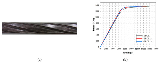
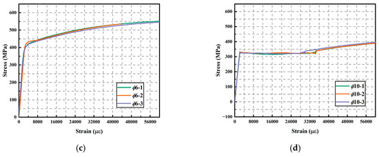
Figure 1.
Longitudinal bars and stirrups used in this study: (a) longitudinal bar, (b) stress–strain curve of longitudinal bars, (c) 6 mm diameter stirrups, and (d) 10 mm diameter stirrups.
As concrete degrades progressively with increasing lateral drift, the shear capacity of columns tends to diminish. To maintain high lateral resistance throughout the deformation range, a dense stirrup configuration was adopted. Given the drift-hardening characteristic of RRC columns, a volumetric stirrup ratio of 2.26% was used to provide adequate confinement to the core concrete and prevent premature degradation. In the shear span region, 6 mm diameter stirrups were arranged at a 50 mm spacing, while in the remaining regions, 10 mm diameter stirrups were used with the same spacing. For column retrofit, 3.2 mm thick steel plates were employed. The edges of the plates were polished, and a 20 mm radius was introduced at each corner to avoid stress concentration. All material properties used in this study are summarized in Table 1.

Table 1.
Material properties.
2.2. Specimen Details
The cross-sectional dimensions of the RRC columns were 250 × 250 mm, with a concrete cover thickness of 25 mm. The shear span of each column was 750 mm, resulting in a shear span-to-depth ratio of 3.0 for all specimens. To facilitate construction and ensure accurate alignment during testing, the column bases were replaced by a set of prefabricated steel blocks, as illustrated in Figure 2a,b. To monitor potential movement at the column base, two linear variable differential transformers (LVDTs) were installed to measure horizontal displacement in the direction of lateral loading. The measured displacements were found to be negligible, confirming the stability of the base during testing. The drift ratio was calculated as the ratio of the displacement measured by the top LVDT to the shear span of 750 mm.
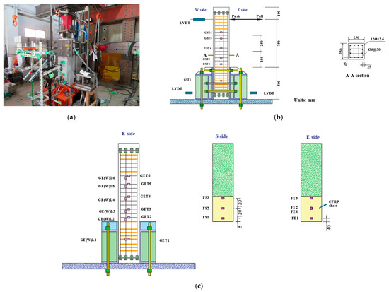
Figure 2.
Loading system and specimen dimensions. (a) Loading system. (b) Specimen dimension. (c) Arrangement of strain gauges.
To prevent out-of-plane tilting, six prestressing steel bars (designated SBPR 1080/1230) with a nominal diameter of 21 mm were used to anchor the column securely in position. During the initial loading phase, an axial load corresponding to an axial load ratio was applied. This axial load ratio was maintained at a constant value of 0.18 across all five RRC column specimens.
The experimental variables included the axial location, retrofit materials, and the fixing methods of steel plates. The specimen names were designated based on their retrofitting configurations to ensure clarity and consistency throughout the paper. For example, the specimen labeled “S3CFRP-SP” indicates that it is specimen number 3, and it is retrofitted with CFRP sheets and additional bonded steel plates. Specimen S1Mortar was the control specimen, which was only retrofitted with high-strength mortar. The parameters of specimens are listed in Table 2.
Table 2.
Experimental parameters of this study.
2.3. Experimental Procedures
Lateral loads were applied using a horizontal actuator with a capacity of 1000 kN and a maximum displacement of 300 mm. The original specimens were first loaded by displacement control (0.25%, 0.5%, 0.75%, 1%, 1.5%, and 2%, with each drift ratio lasting two cycles and one cycle at a 3% drift ratio) to simulate the damage induced by strong earthquakes. Following the initial loading phases, all damaged specimens were retrofitted mainly through a four-step procedure: (1) removal of loose and deteriorated concrete followed by restoration of column integrity using high-strength mortar; (2) injection of epoxy resin into the column to fill internal cracks; (3) installation of steel plates on the column surfaces; and (4) external wrapping of the columns with CFRP sheets. Upon completion of the retrofit process, the specimens were subjected to reloading (0.25%, 0.5%, 0.75%, 1%, 1.5%, and 2%, with each drift ratio lasting two cycles, and 3%, 4%, 5%, and 8%, with each drift ratio lasting one cycle for S1Mortar; 3%, 4%, 5%, 6%, 7%, and 8%, with each drift ratio lasting one cycle for other specimens) up to a target drift ratio of 8%. The detailed test processes are shown in Figure 3. It is noteworthy that, even at this large deformation level, no shear failure was observed in the retrofitted RRC columns, and the experiment was terminated here based on the consideration of the experimenters’ safety. Furthermore, there was no noticeable degradation in lateral load-carrying capacity, indicating that the columns maintained excellent deformation capacity post-retrofit.
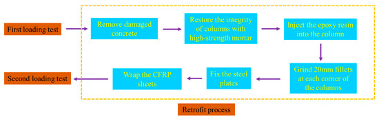
Figure 3.
Experimental processes in this study.
3. Results
3.1. Hysteresis Behavior
During both loading phases, all specimens predominantly exhibited a flexural failure mode. As shown in Figure 4, the columns continued to demonstrate the characteristic drift-hardening behavior, with no significant degradation in lateral load capacity observed even at a drift ratio of 8% after retrofit. After the yielding of the longitudinal reinforcement, the lateral load continued to increase slightly, reflecting the resilience of the structural system. The hysteresis responses revealed a pronounced pinching effect, primarily attributed to the slip of the longitudinal bars, indicating that residual displacements were effectively controlled through the use of ultra-high-strength steel reinforcement.
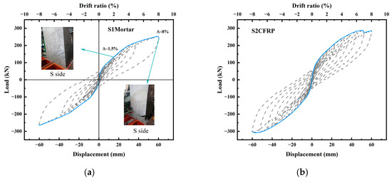
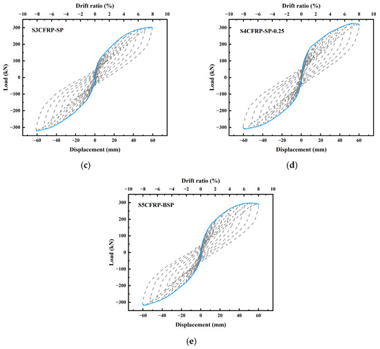
Figure 4.
Hysteresis curves of specimens. (a) S1Mortar. (b) S2CFRP. (c) S3CFRP-SP. (d) S4CFRP-SP-0.25. (e) S5CFRP-BSP.
The characteristic points of each specimen, including the yield point (defined as the stage when the steel bars begin to yield), the peak point (corresponding to the maximum lateral load), and the ultimate point (indicating the maximum displacement), were identified and are presented in Figure 5. The results indicated that the inclusion of steel plates contributed to an increase in peak lateral load. Furthermore, specimens in which the steel plates were anchored using both expansion bolts and epoxy resin (Specimen S5CFRP-BSP) exhibited superior performance compared to those using epoxy resin alone (Specimen S3CFRP-SP). Specifically, the hysteresis curves of S5CFRP-BSP were fuller, reflecting enhanced energy dissipation capacity due to improved plate anchorage. Additionally, an increase in the applied axial load was found to result in a noticeable enhancement of the maximum lateral load capacity.
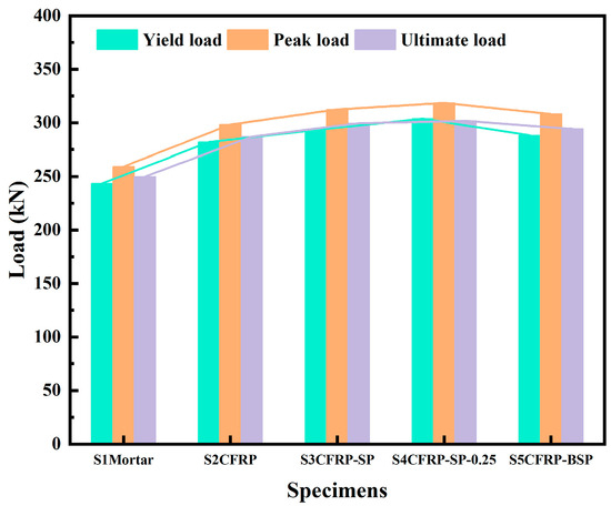
Figure 5.
Characteristic points of specimens.
Compared with the control specimen, S1Mortar, the yield load of Specimen S2CFRP increased by approximately 15%, indicating that the application of CFRP sheets can effectively restore lateral load-carrying capacity. For specimens retrofitted using both thin steel plates and CFRP sheets, the peak load was further enhanced. Specifically, the yield loads of Specimens S3CFRP-SP (293.25 kN) and S5CFRP-BSP (288.25 kN) were 20.4% and 18.4% higher than that of the control specimen (243.5 kN), respectively. These results suggest that the addition of external steel plates is beneficial for restoring and enhancing lateral resistance. Based on these findings, it is hypothesized that the application of pre-stress to the steel plates could further improve the retrofit effectiveness. Pre-stressing may help constrain crack propagation and increase the initial stiffness of the column. Following CFRP sheet retrofit, an increase in yield load was consistently observed. The yield loads of Specimens S2CFRP (282 kN) increased by 15.8% compared to the control column. This improvement may be attributed to the CFRP sheets enhancing the flexural deformation capacity, promoting a more uniform stress distribution, and delaying the yielding of longitudinal reinforcement. Additionally, the presence of higher axial loads contributed to increased yield loads.
Although Specimens S3CFRP-SP and S5CFRP-BSP exhibited similar yield and peak loads, the differences were minimal—1.7% for the yield load and 1.4% for the peak load. This indicates that the steel plate fixation method had a limited influence on these two parameters. The trend in the ultimate load followed that of the peak load, with increases of 14.8% and 19.8% observed for Specimens S2CFRP and S3CFRP-SP, respectively, compared to the control specimen. The increase in axial load had only a marginal effect on the ultimate load of columns retrofitted with CFRP sheets and steel plates.
3.2. Stiffness Degradation
The secant stiffness at the first cycle of each drift ratio was calculated and normalized to evaluate the stiffness degradation and recovery behavior of the retrofitted RRC columns. As shown in Figure 6a, the stiffness degraded rapidly before the drift ratio reached 1%, with all specimens retaining approximately 50% of their initial stiffness at that point. Between 1% and 4% drift ratios, the degradation rate slowed significantly, and the stiffness remained between 25% and 50% of the initial value. Beyond a 4% drift ratio, stiffness stabilized at approximately 20% of the initial value up to the maximum tested drift ratio of 8%. Notably, specimens subjected to higher axial loads experienced a faster stiffness degradation rate.
Figure 6.
Stiffness degradation and stiffness recovery rate of specimens. (a) Stiffness degradation rate. (b) Stiffness recovery rate.
Figure 6a indicates that Specimen S1Mortar exhibited a slower stiffness degradation rate. This behavior is attributed to its lower initial stiffness compared to other retrofitted columns. To facilitate a more accurate comparison of stiffness recovery across different retrofit techniques, the stiffness recovery rate was proposed, defined as the ratio of the secant stiffness of the retrofitted column to that of the original column at the same drift ratio.
As shown in Figure 6b, the control specimen, S1Mortar, consistently exhibited the lowest stiffness recovery rate across all drift ratios. In contrast, Specimen S5CFRP-BSP demonstrated the highest recovery rate at nearly every drift level. At the initial 0.25% drift ratio, the stiffness recovery rates of most retrofitted specimens reached approximately 90%, except for the control column, which only used high-strength mortar and recovered about 50%. This confirms that combining high-strength mortar and CFRP sheets significantly improves stiffness restoration.
Among the composite retrofit techniques, Specimen S5CFRP-BSP (with steel plates mechanically anchored using expansion bolts) outperformed Specimen S3CFRP-SP (with bonded steel plates), highlighting the effectiveness of mechanical fixation. The bolted steel plates provided better confinement and bridging over both damaged and undamaged concrete regions, enhancing the overall structural integrity.
Similarly, the stiffness recovery rate at a 1% drift ratio for Specimens S2CFRP and S3CFRP-SP reached 85.2% and 95.7%, respectively. Beyond a 1% drift, Specimen S3CFRP-SP continued to exhibit a higher stiffness recovery rate than S2CFRP, reinforcing the role of internal steel plates in promoting effective stiffness restoration. It is also worth noting that the stiffness recovery rate tended to increase with the drift ratio, even for the control specimen. This can be attributed to the significant reduction in the original column’s stiffness at large deformations, making recovery appear more substantial in relative terms. Additionally, under a slightly higher axial load ratio of 0.25, a marginally greater stiffness recovery rate was observed, likely due to the increased absolute stiffness resulting from higher axial confinement. In summary, the use of CFRP sheets in combination with steel plates—particularly those fixed with bolts—proved to be highly effective in restoring the stiffness of earthquake-damaged RRC columns.
3.3. Energy Dissipation
The area enclosed by the hysteresis curves was used to quantify the energy dissipation capacity of the RRC columns. The cumulative energy dissipation was obtained by summing the area under the curves at each drift ratio. As shown in Figure 7a, all retrofitted RRC columns demonstrated higher energy dissipation capacities compared to the control specimen. In particular, the columns retrofitted with CFRP sheets exhibited superior energy dissipation at almost every drift level. This improvement is attributed to the confinement effect provided by the CFRP sheets, which restrained concrete deformation and enhanced its stress–strain response, thereby increasing the peak compressive strength. Furthermore, the cumulative energy dissipation increased with higher axial load ratios due to the corresponding increase in lateral resistance. For example, the cumulative energy dissipation of Specimen S4CFRP-SP-0.25 was 9.1% higher than that of Specimen S3CFRP-SP, highlighting the influence of an axial load on seismic energy absorption.
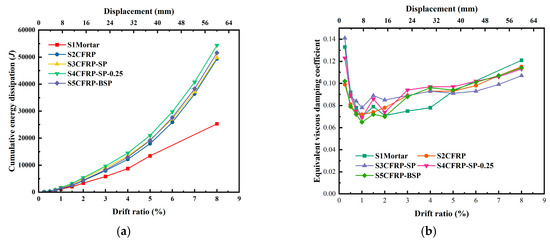
Figure 7.
Energy dissipation and heq of specimens. (a) Cumulative energy dissipation. (b) heq.
While Specimen S3CFRP-SP and Specimen S5CFRP-BSP exhibited nearly identical energy dissipation up to a 6% drift ratio, a slight decrease was observed for Specimen S3CFRP-SP beyond this point. This suggests that the fixation method of the steel plate had only a minor impact on the overall energy dissipation. Additionally, the energy dissipation capacity of Specimen S2CFRP was comparable to that of Specimen S3CFRP-SP, with a difference of less than 4.5% at the 8% drift ratio. This indicates the relatively small contribution of thin steel plates to energy dissipation in this context.
Another parameter commonly used to evaluate the energy dissipation performance is the equivalent viscous damping coefficient, heq, which is defined in [29]. As shown in Figure 7b, the heq values for all retrofitted columns initially decreased before reaching a drift ratio of 1.0%, after which they gradually increased with increasing deformation. At the 0.25% drift ratio, the heq values ranged from 0.099 to 0.141, with Specimen S2CFRP showing the lowest value and Specimen S3CFRP-SP showing the highest value. A comparison between Specimens S3CFRP-SP and S4CFRP-SP-0.25, which differed only in the axial load ratio (0.18 vs. 0.25), revealed that increasing the axial load had a slightly negative effect on the damping performance. The minimum and maximum heq values for Specimen S3CFRP-SP were 0.078 and 0.141, respectively, while those for Specimen S4CFRP-SP-0.25 were 0.069 and 0.123. Throughout the loading process, Specimen S5CFRP-BSP exhibited the lowest heq value of 0.065 at the 1.0% drift ratio. These results suggest that while the CFRP and steel plate retrofit methods improve energy dissipation, the effect of the steel plate fixation method and the axial load ratio on energy dissipation is relatively limited, especially in terms of the equivalent viscous damping coefficient.
3.4. Residual Displacement
Residual displacement is a key indicator in evaluating the post-earthquake repairability of RC columns. It is generally accepted that a column is considered repairable if the residual drift ratio remains below 0.5%. As shown in Figure 8, all retrofitted specimens maintained residual drift ratios below 0.5% up to approximately a 3.5% drift ratio. This observation highlights the excellent resilience retained by the retrofitted RRC columns, suggesting that structural systems incorporating such columns can be restored rapidly after a seismic event. Interestingly, the increase in axial load ratio did not result in higher residual displacements for the specimens retrofitted with CFRP sheets and steel plates. This finding contrasts with results reported in previous studies, which typically associate increased axial load with greater residual drift. Compared to the control specimen, the CFRP-retrofitted specimen exhibited slightly reduced residual displacement, demonstrating the effectiveness of CFRP sheets in improving post-yield behavior and residual control.
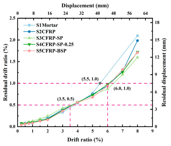
Figure 8.
Residual deformation of retrofitted columns.
When comparing different retrofit strategies, specimens retrofitted with both CFRP and steel plates showed similar residual displacements to those retrofitted with CFRP alone up to a 7% drift ratio. However, at an 8% drift ratio, the combination retrofit approach produced noticeably lower residual displacements. In particular, Specimen S5CFRP-BSP, which incorporated bolted steel plates, exhibited smaller residual displacements than Specimen S3CFRP-SP (with bonded steel plates) across all drift levels up to 8%. This outcome indicates that the mechanical fixation of steel plates contributes positively to residual displacement control in retrofitted RRC columns.
According to FEMA guidelines [30], an RC column is considered repairable when its residual drift ratio remains below 1.0%. All retrofitted RRC columns met this criterion up to a 6.0% drift ratio, reflecting their superior repairability. In contrast, the control column—retrofitted only with high-strength mortar—exceeded the 1.0% threshold at a 5.5% drift ratio due to the accumulation of irreversible damage. These results confirm the efficacy of CFRP and steel plate reinforcement in restoring and enhancing the post-earthquake performance of RRC columns.
3.5. Strain Distribution of Reinforcing Materials
3.5.1. Strain Distribution of Longitudinal Bars
The strain distribution of longitudinal bars is illustrated in Figure 9. The solid line represents the strain distribution in the push direction, while the dashed line denotes the pull direction. GEL indicates that the longitudinal bar is placed on the east side of the column, while GWL denotes placement on the west side. Some strain gauge data were excluded due to excessive column deformation or damage caused by concrete casting. Figure 9 shows that the longitudinal bars first reached their yield strain at approximately a 6% drift ratio. Before yielding, the strain distribution was nearly linear along the column height and decreased gradually with increasing elevation. The strain gauge at a height of 100 mm exhibited faster strain development than other locations, particularly after yielding, as a plastic hinge formed in this region, accelerating strain accumulation. The tensile strain was significantly larger than the compressive strain, and longitudinal bars typically yielded in response to tension.
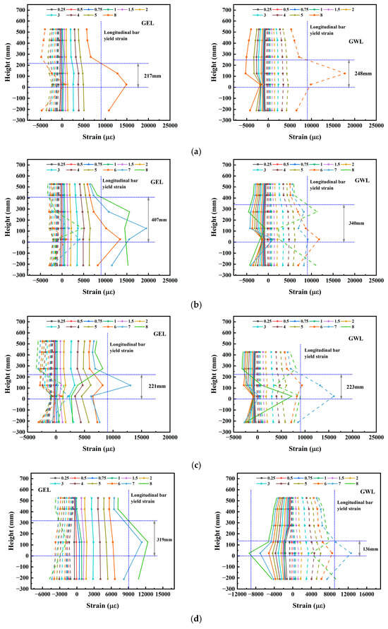
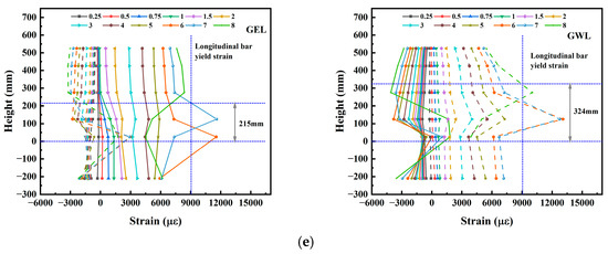
Figure 9.
Strain distribution of longitudinal bars on the east and west sides of the specimens. (a) S1Mortar. (b) S2CFRP. (c) S3CFRP-SP. (d) S4CFRP-SP-0.25. (e) S5CFRP-BSP.
In Figure 9, the vertical blue dashed line indicates the yield strain of the longitudinal bars, and the height of the intersection point represents the plastic hinge length (PHL) at the ultimate drift ratio of 8%. The control column exhibited a relatively short PHL of approximately 250 mm, which is equal to the column cross-sectional width (D). In contrast, Specimen S2CFRP demonstrated an increased PHL of about 400 mm (1.6 D), suggesting that the CFRP sheets enhanced the flexural capacity of the reinforced concrete (RC) column. The introduction of steel plates reduced the PHL, whereas an increase in axial load resulted in a larger maximum PHL, as illustrated in Figure 9b–d. The bolt-fixed steel plate configuration exhibited a maximum PHL of approximately 320 mm (1.28 D), similar to that of the specimen under high axial load.
For the strain gauges GEL2 (pull direction) and GWL2 (push direction), the strain direction reversed noticeably at drift ratios exceeding 6%. To facilitate further analysis, Figure 10 presents the strain development of longitudinal bars in Specimen S2CFRP. The strain gauges GEL5 (GWL5) and GEL6 (GWL6), located at heights of 425 mm and 525 mm, did not yield during the entire loading process, and their strain values varied consistently with horizontal displacement. In contrast, the strain gauges GEL1 (GWL1) and GEL4 (GWL4), positioned at −210 mm and 275 mm, reached the yield strain at around a 6% drift ratio, followed by rapid strain development, resulting in an enlarged enclosed area in the strain–displacement curve. Meanwhile, the strain gauges GEL2 (GWL2) and GEL3 (GWL3), situated within the plastic hinge region, underwent intense fluctuations after a 5% drift ratio, with their curves exhibiting a near-vertical increase upon steel bar yielding.
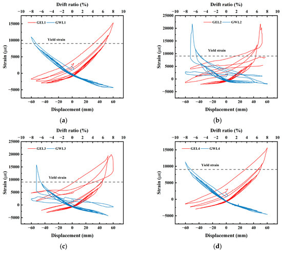
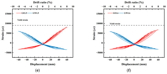
Figure 10.
Strain development of longitudinal bars on the east and west sides of Specimen S2CFRP. (a) GEL1 (GWL1). (b) GEL2 (GWL2). (c) GEL3 (GWL3). (d) GEL4 (GWL4). (e) GEL5 (GWL5). (f) GEL6 (GWL6).
3.5.2. Strain Distribution of Stirrups
Figure 11 presents the strain distribution of stirrups, with the solid line indicating the strain distribution in the push direction and the dashed line representing the pull direction. GST indicates that the stirrup is placed on the south side of the column, while GET denotes placement on the east side. The results demonstrate that the stirrups remained below the yield strain throughout most of the loading process, except for Specimen S4CFRP-SP-0.25 under high axial loading. The strain within the plastic hinge region showed significant increases with higher drift ratios, particularly after exceeding a 3% drift. When compared to the control column, Specimen S2CFRP exhibited notably higher strain values in the plastic hinge region on the east side at an 8% drift ratio. However, these strains remained below the stirrup yield strain of 4200 µε. In contrast, strain measurements on the south side showed minimal variation, as this region was dominated by shear strain rather than tensile strain, particularly during large deformation stages. Specimen S3CFRP-SP displayed slightly reduced strain values in the plastic hinge region, with measurements below 1200 µε on both the south and east sides. This observation suggests that the steel plate’s presence may have reduced the maximum stirrup strains, likely due to the enhanced confinement effect provided by the steel plate.

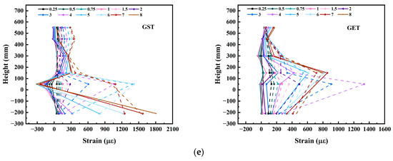
Figure 11.
Strain distribution of stirrups on the south and east sides of the specimens. (a) S1Mortar. (b) S2CFRP. (c) S3CFRP-SP. (d) S4CFRP-SP-0.25. (e) S5CFRP-BSP.
The experimental data further revealed that increased axial loading led to higher stirrup strains, particularly on the east side. At a 6% drift ratio, east-side stirrup strains exceeded yield levels, while south-side strains remained below 1500 µε. This behavior can be attributed to additional deformation caused by the higher axial load, which induced greater concrete expansion and consequently increased stirrup strains. Comparative analysis between Specimen S3CFRP-SP and Specimen S5CFRP-BSP indicated that bolt-fixed steel plates resulted in marginally higher maximum strains in the plastic hinge region for both the south and east sides. However, given the observed irregularities in stirrup strain distribution patterns, additional experimental verification would be necessary to confirm these findings.
3.5.3. Strain Distribution of CFRP
Figure 12 illustrates the development of CFRP sheet hoop strain on both the south and east sides. On the south side, Specimen S2CFRP exhibited slightly higher strain values during early loading stages compared to specimens with steel plates. This observation indicates that while the steel plates provided some initial restraint, their effectiveness was limited, as evidenced by the relatively small strain variations between specimens.
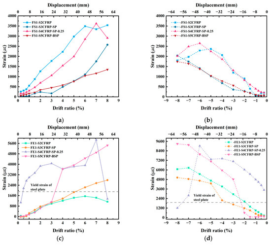
Figure 12.
Development of CFRP hoop strain on the south and east sides of the column. (a) Strain of FS1 in the push direction. (b) Strain of FS1 in the pull direction. (c) Strain of FE1 in the push direction. (d) Strain of FE1 at pull direction.
The method of steel plate attachment significantly influenced CFRP strain behavior. On the south side, bolt-fixed steel plates reduced push-direction CFRP strain more substantially than epoxy-bonded plates, while pull-direction strains showed minimal variation. The axial load magnitude markedly affected CFRP hoop strain development, with high axial load conditions producing strains approximately 2.6 times greater in the push direction and 1.9 times greater in the pull direction at a 6% drift ratio compared to low axial load conditions. Steel plate implementation reduced south-side CFRP hoop strains by 68% in the push direction and 38% in the pull direction at a 6% drift ratio.
The behavior on the east side differed significantly due to pronounced steel plate compression during large deformations, resulting in dramatic CFRP hoop strain increases (Figure 12c,d). Pull-direction strains substantially exceeded push-direction values on the east side, primarily due to additional steel plate deformation. Following steel plate yielding, rapid deformation development caused abrupt CFRP strain escalation. While steel plates generally reduced CFRP strain (Figure 12d), Specimen S5CFRP-BSP exhibited notable strain increases after steel plate yielding at a 2% drift ratio. High axial loading conditions generated elevated east-side CFRP hoop strains, with maximum pull-direction strain reaching 9032 µε compared to 5872 µε in the push direction. This directional disparity stems from distinct concrete stress states: in the pull direction, the concrete on the east side experienced compression that led to severe expansion deformation, while the push direction produced tension effects. The compressive stresses during pulling consequently induced more substantial concrete expansion and associated CFRP straining.
Figure 13 presents vertical strain development on the east side of the specimens. The results clearly demonstrate that the implementation of steel plates significantly reduced vertical strain. Importantly, the observed vertical strain values were substantial and therefore cannot be neglected, indicating that biaxial stress conditions must be considered when using FRP sheets for RC column retrofit. This finding suggests that biaxial FRP sheets would be more appropriate for such applications. As expected, higher axial loads generally resulted in greater vertical strains. However, Figure 13b reveals an interesting exception: Specimen S5CFRP-BSP exhibited larger vertical strains than both Specimen S3CFRP-SP and Specimen S4CFRP-SP-0.25 beyond a 4% drift ratio. This phenomenon can be attributed to steel plate yielding, where subsequent plate buckling introduces additional deformation. Notably, despite these increased strains, the CFRP sheets maintained their integrity without rupture, demonstrating excellent deformation capacity under these demanding conditions.
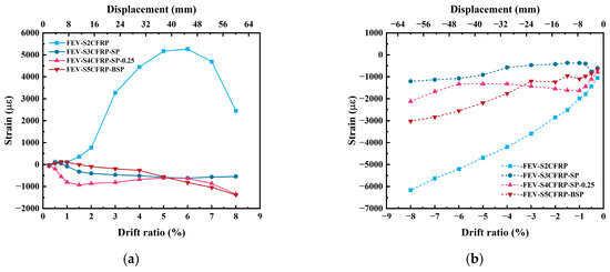
Figure 13.
Development of CFRP axial strain on the east side of the column. (a) Strain of FEV in the push direction. (b) Strain of FEV at pull direction.
4. Improvement Mechanism of Additional Steel Plates
The seismic performance of RRC columns retrofitted with CFRP sheets and steel plates can be further evaluated through a comparative analysis of the skeleton curves shown in Figure 14. During the initial loading stage, the steel plate acts as a bridging mechanism that effectively connects the damaged concrete with the newly applied high-strength mortar, both in the hoop and axial directions. Moreover, the steel plate helps restrain crack propagation initiated during the first loading phase and prevents the development of new cracks. Consequently, specimens incorporating steel plates demonstrate a higher stiffness recovery rate than the control specimen. Among these, the steel plate fixed using both expansion bolts and epoxy resin outperformed the specimen where the plate was bonded solely with epoxy, as observed in Specimens S5CFRP-BSP and S3CFRP-SP. The earlier engagement of mechanically fixed steel plates enhances their restraining effectiveness compared to bonded configurations.
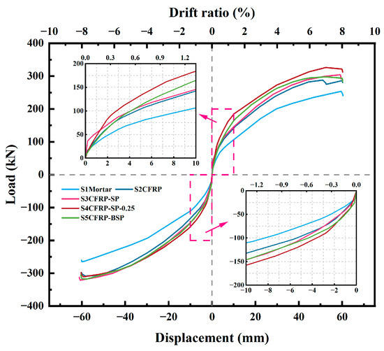
Figure 14.
Skeleton curves of specimens.
This improvement can be attributed not only to the better physical anchorage provided by expansion bolts but also to the more uniform stress transfer from steel plates to the surrounding retrofit materials. As a result, steel plate-strengthened specimens exhibited a more stable hysteretic response and delayed stiffness degradation throughout the cyclic loading. In particular, S5CFRP-BSP maintained a more symmetrical and fuller hysteresis loop at larger drift ratios, indicating enhanced energy dissipation capacity and ductility. Additionally, the presence of steel plates reduced the tendency for localized CFRP overstretching and rupture by distributing the tensile forces more evenly along the retrofit zone.
Due to this enhanced crack control, columns retrofitted with both CFRP sheets and steel plates showed improved lateral resistance and stiffness recovery relative to those retrofitted with CFRP sheets alone. As lateral displacement increased, axial strain in the CFRP sheets also increased, potentially diminishing the CFRP’s confinement effectiveness. In this study, the CFRP was applied in the hoop direction using epoxy resin; however, axial tensile forces may degrade the bond between the fibers and the resin. This issue was particularly evident in Specimen S2CFRP, which was retrofitted using only CFRP sheets and exhibited a maximum axial strain value exceeding 6000 µε. In RC columns fully wrapped with FRPs, a loss of aggregate interlock in the concrete has been observed at fiber strains lower than the ultimate tensile strain of the FRP. To prevent such premature failure, the design strain for fully wrapped members should be limited to 4000 µε, as recommended by ACI 440.2R-17 [31]. These findings underscore the need to account for excessive axial strain in future studies.
In contrast, the incorporation of steel plates significantly reduced the axial strain in the CFRP sheets, thereby preserving their confinement effect, as demonstrated by Specimens S3CFRP-SP and S5CFRP-BSP. Moreover, Figure 14 showed that under both push and pull loading directions, the steel plate-strengthened specimens achieved average peak lateral loads exceeding 300 kN, which was a little higher than Specimen S2CFRP. Among these, S5CFRP-BSP demonstrated the most stable and symmetrical response, suggesting superior energy dissipation and reduced stiffness degradation across load cycles. The specimen under a higher axial load ratio (S4CFRP-SP-0.25) showed the highest lateral strength and stiffness, confirming the importance of the axial load ratio in determining the overall retrofit effectiveness.
As shown in Figure 14, once lateral displacement reached 2.44 mm (0.325% drift ratio) in the push direction and 2.9 mm (0.387% drift ratio) in the pull direction, all specimens retrofitted with both CFRP sheets and steel plates exhibited higher lateral strength than the specimen retrofitted solely with CFRP. Notably, Specimen S5CFRP-BSP consistently achieved higher average lateral strength (calculated from the push and pull directions) than Specimen S3CFRP-SP throughout the test, highlighting the superior performance of mechanical fixation. Furthermore, S5CFRP-BSP exhibited lower CFRP axial strain at large deformations, confirming that reduced axial strain contributes to more effective retrofit of earthquake-damaged RRC columns. These results collectively demonstrate that the synergy between CFRP confinement and bolted steel plate anchorage offers a reliable and practical retrofitting solution for earthquake-damaged RC members. The bolted anchorage method is practical for field application and does not impose excessive complexity during installation.
5. Conclusions
This study investigated the seismic performance of RRC columns retrofitted using various methods. Based on the experimental results and analysis, the following conclusions can be drawn:
(1) High-strength mortar alone preserved the resilience characteristics of drift-hardening and self-centering behavior but provided limited improvement in lateral load capacity. The use of CFRP sheets significantly enhanced lateral resistance beyond a 3% drift ratio, albeit with relatively limited stiffness at early stages. The addition of steel plates further increased peak load capacity, with mechanically anchored steel plates (bolts and epoxy) proving more effective than epoxy bonding alone. While increasing the axial load ratio led to a clear enhancement in maximum lateral load, the ultimate load of CFRP- and steel plate-retrofitted specimens remained relatively unchanged.
(2) The secant stiffness degradation of retrofitted RRC columns followed a three-stage pattern: (i) rapid decline (0.25–1.0% drift), (ii) gradual decline (1.0–4.0%), and (iii) stabilization (4.0–8.0%). Stiffness degraded more rapidly under higher axial loads. The control specimen (S1Mortar) showed the lowest stiffness recovery rate, while the specimen with mechanically fixed steel plates (S5CFRP-BSP) achieved the highest rate across nearly all drift ratios. The combined use of high-strength mortar and CFRP sheets effectively restored stiffness. Mechanically anchored steel plates (S5CFRP-BSP) outperformed bonded plates (S3CFRP-SP), demonstrating superior stiffness recovery.
(3) CFRP-retrofitted specimens demonstrated greater energy dissipation capacity than the control. Cumulative energy dissipation increased with higher axial loads. The steel plate fixation method had a minimal impact on overall energy dissipation capacity. The heq initially declined before a 1.0% drift and increased thereafter.
(4) Retrofitted columns exhibited residual drift ratios below 0.5% at approximately a 3.5% drift, maintaining good self-centering and indicating high repairability. CFRP- and steel plate-retrofitted specimens remained below the 1.0% residual drift limit up to a 6.0% drift ratio. Increased axial load did not result in greater residual displacement for CFRP- and steel plate-retrofitted specimens.
(5) The plastic hinge length of the control column was approximately 250 mm (equal to the column section width, D). CFRP retrofitting increased the PHL to 400 mm (1.6 D), while the introduction of steel plates reduced the PHL. Increased axial load led to a longer maximum PHL. Mechanically anchored steel plates resulted in a PHL of approximately 320 mm (1.28 D), similar to that observed in specimens under higher axial loads.
(6) Steel plate confinement effectively reduced CFRP hoop strain by 68% in the push direction and 38% in the pull direction at a 6% drift. The axial strain in CFRP sheets was also significantly reduced by steel plates. Given the large axial strain values observed, it is essential to consider biaxial stress conditions when employing FRP sheets for the seismic retrofit of RC columns.
Author Contributions
Investigation, Y.H., G.C., A.S.L., P.B.M., and C.X.; writing—original draft preparation, Y.H.; writing—review and editing, G.C.; supervision, G.C. and A.S.L. All authors have read and agreed to the published version of the manuscript.
Funding
This research was funded by the IROAST and China Scholarship Council, China The grant number is 202207040023.
Data Availability Statement
The data presented in this study are available on request.
Acknowledgments
The study was supported by IROAST of Kumamoto University.
Conflicts of Interest
The authors declare no conflicts of interest.
References
- Işık, E.; Avcil, F.; Hadzima-Nyarko, M.; İzol, R.; Büyüksaraç, A.; Arkan, E.; Radu, D.; Özcan, Z. Seismic performance and failure mechanisms of reinforced concrete structures subject to the earthquakes in Türkiye. Sustainability 2024, 16, 6473. [Google Scholar] [CrossRef]
- Ye, L.P.; Zhang, K.; Zhao, S.H.; Feng, P. Experimental study on seismic strengthening of RC columns with wrapped CFRP sheets. Constr. Build. Mater. 2003, 17, 499–506. [Google Scholar] [CrossRef]
- Ma, G.; Li, H. Experimental study of the seismic behavior of predamaged reinforced-concrete columns retrofitted with basalt fiber–reinforced polymer. J. Compos. Constr. 2015, 19, 04015016. [Google Scholar] [CrossRef]
- Ozcan, O.; Binici, B.; Ozcebe, G. Improving seismic performance of deficient reinforced concrete columns using carbon fiber-reinforced polymers. Eng. Struct. 2008, 30, 1632–1646. [Google Scholar] [CrossRef]
- Del Zoppo, M.; Di Ludovico, M.; Balsamo, A.; Prota, A.; Manfredi, G. FRP for seismic strengthening of shear-controlled RC columns: Experience from earthquakes and experimental analysis. Compos. Part B Eng. 2017, 129, 47–57. [Google Scholar] [CrossRef]
- Li, G.; Kidane, S.; Pang, S.S.; Helms, J.E.; Stubblefield, M.A. Investigation into FRP-repaired RC columns. Compos. Struct. 2003, 62, 83–89. [Google Scholar] [CrossRef]
- Sun, D.; Dai, J.; Huang, S.; Huang, Y. Rapid repair of seismic damaged short RC piers with CFRP composite strengthening method. Structures 2025, 71, 108201. [Google Scholar] [CrossRef]
- Al Ekkawi, A.; El-Hacha, R. Experimental investigation on seismically deficient RC bridge columns strengthened with prestressed vertical Fe-SMA plates and confined with CFRP wraps and UHPFRC jacket. Eng. Struct. 2025, 332, 120010. [Google Scholar] [CrossRef]
- Işık, E.; Radu, D.; Harirchian, E.; Avcil, F.; Arkan, E.; Büyüksaraç, A.; Hadzima-Nyarko, M. Failures in Reinforced-Concrete Columns and Proposals for Reinforcement Solutions: Insights from the 2023 Kahramanmaraş Earthquakes. Buildings 2025, 15, 1535. [Google Scholar] [CrossRef]
- He, R.; Grelle, S.; Sneed, L.H.; Belarbi, A. Rapid repair of a severely damaged RC column having fractured bars using externally bonded CFRP. Compos. Struct. 2013, 101, 225–242. [Google Scholar] [CrossRef]
- Elci, H. Seismic strengthening of improperly repaired reinforced concrete columns using CFRP confinement. Structures 2020, 28, 266–275. [Google Scholar] [CrossRef]
- Youm, K.S.; Lee, H.E.; Choi, S. Seismic performance of repaired RC columns. Mag. Concr. Res. 2006, 58, 267–276. [Google Scholar] [CrossRef]
- Yalcin, C.; Kaya, O.; Sinangil, M. Seismic retrofitting of R/C columns having plain rebars using CFRP sheets for improved strength and ductility. Constr. Build. Mater. 2008, 22, 295–307. [Google Scholar] [CrossRef]
- Wu, Y.F.; Wei, Y.Y. Effect of cross-sectional aspect ratio on the strength of CFRP-confined rectangular concrete columns. Eng. Struct. 2010, 32, 32–45. [Google Scholar] [CrossRef]
- Binici, B. Design of FRPs in circular bridge column retrofits for ductility enhancement. Eng. Struct. 2008, 30, 766–776. [Google Scholar] [CrossRef]
- Thermou, G.E.; Pantazopoulou, S.J. Fiber-reinforced polymer retrofitting of predamaged substandard RC prismatic members. J. Compos. Constr. 2009, 13, 535–546. [Google Scholar] [CrossRef]
- Pinho, R. Selective Retrofitting of RC Structures in Seismic Areas. Ph.D. Thesis, University of London, London, UK, 2000. [Google Scholar]
- Lu, X.; Liu, B.; Sun, W.; Xu, L. Seismic performance investigation on self-centering friction frames: Collapse capacity and post-earthquake recovery. Soil Dyn. Earthq. Eng. 2024, 179, 108555. [Google Scholar] [CrossRef]
- Qian, H.; Kang, L.; Li, Z.; Shi, Y.; Wang, X.; Li, H. Hysteretic Behavior of Self-Centering Shear Wall Incorporating Superelastic Shape Memory Alloy Bars and Engineered Cementitious Composites Subjected to Cyclic Loading. J. Struct. Eng. 2024, 150, 04024119. [Google Scholar] [CrossRef]
- Sun, Y.P.; Cai, G.C. Seismic behavior of circular concrete columns reinforced by low bond ultrahigh strength rebars. J. Struct. Eng. 2023, 149, 04023126. [Google Scholar] [CrossRef]
- Zhang, J.; Liu, X.; Liu, J.; Zhang, M.; Cao, W. Seismic performance and reparability assessment of recycled aggregate concrete columns with ultra-high-strength steel bars. Eng. Struct. 2023, 277, 115426. [Google Scholar] [CrossRef]
- Priestley, M.N.; Tao, J.R. Seismic response of precast prestressed concrete frames with partially debonded tendons. PCI J. 1993, 38, 58–69. [Google Scholar] [CrossRef]
- Liu, X.; Zhang, J.; Liu, J.; Zhang, M.; Cao, W. Seismic performance and damage assessment of earthquake-damaged HSRAC columns with UHSS repaired by CFRP jackets. Structures 2023, 48, 241–257. [Google Scholar] [CrossRef]
- Funato, Y.; Sun, Y.; Takeuchi, T.; Cai, G. Modeling and application of bond characteristic of high-strength reinforcing bar with spiral grooves. Proc. Jpn. Concr. Inst. 2012, 34, 157–162. [Google Scholar]
- Zhang, M.; Zhang, J.; Sun, Y.; Tao, X. Seismic performance and analysis of resilient high-strength SRAC walls. Eng. Struct. 2023, 296, 116943. [Google Scholar] [CrossRef]
- Takeuchi, T.; Sun, Y.; Tani, M.; Shing, P.S.B. Seismic performance of concrete columns reinforced with weakly bonded ultrahigh-strength longitudinal bars. J. Struct. Eng. 2021, 147, 04020290. [Google Scholar] [CrossRef]
- Cai, R.; Zhang, J.; Liu, Y.; Tao, X. Seismic behavior of recycled concrete columns reinforced with ultra-high-strength steel bars. Eng. Struct. 2023, 279, 115633. [Google Scholar] [CrossRef]
- Xiao, Y.; Wu, H. Compressive behavior of concrete confined by carbon fiber composite jackets. J. Mater. Civ. Eng. 2000, 12, 139–146. [Google Scholar] [CrossRef]
- Jacobsen, L.S. Damping of composite structures. In Proceedings of the 2nd World Conference on Earthquake Engineering, Tokyo, Japan, 11–18 July 1960. [Google Scholar]
- FEMA P-58-1; Seismic Performance Assessment of Buildings, Volume 1—Methodology. Federal Emergency Management Agency: Washington, DC, USA, 2012.
- ACI 440-2R-17; Guide for the Design and Construction of Externally Bonded FRP Systems for Strengthening Concrete Structures. American Concrete Institute: Farmington Hills, MI, USA, 2017.
Disclaimer/Publisher’s Note: The statements, opinions and data contained in all publications are solely those of the individual author(s) and contributor(s) and not of MDPI and/or the editor(s). MDPI and/or the editor(s) disclaim responsibility for any injury to people or property resulting from any ideas, methods, instructions or products referred to in the content. |
© 2025 by the authors. Licensee MDPI, Basel, Switzerland. This article is an open access article distributed under the terms and conditions of the Creative Commons Attribution (CC BY) license (https://creativecommons.org/licenses/by/4.0/).