
Three-Dimensional Printing Experiments and Particle-Based Meshless Numerical Investigations on the Failure Modes of Tunnel-Lining Structures Containing Fissures


Abstract
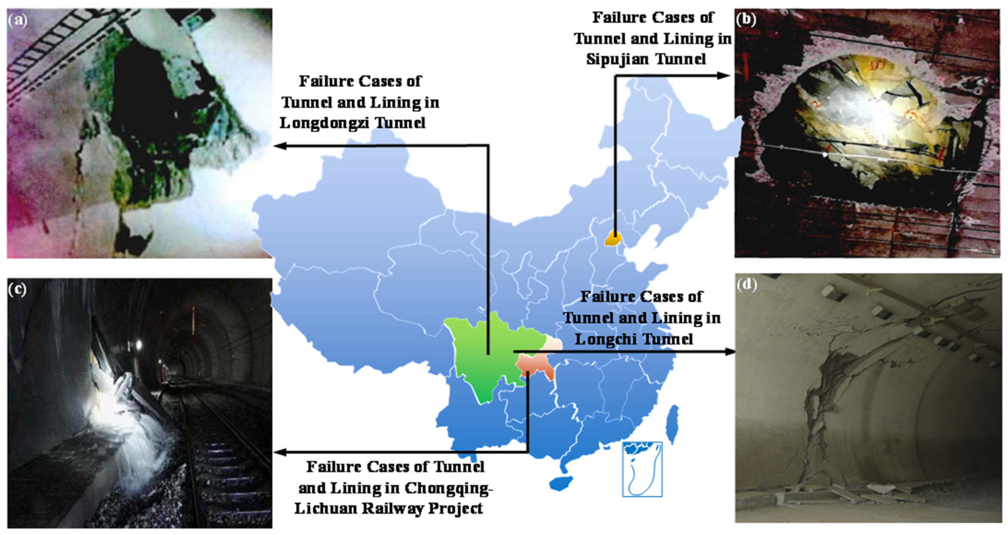
1. Introduction
2. Experimental Schemes
2.1. Principles of DIC
2.2. Specimen Preparations and Experimental Processes
- (1)
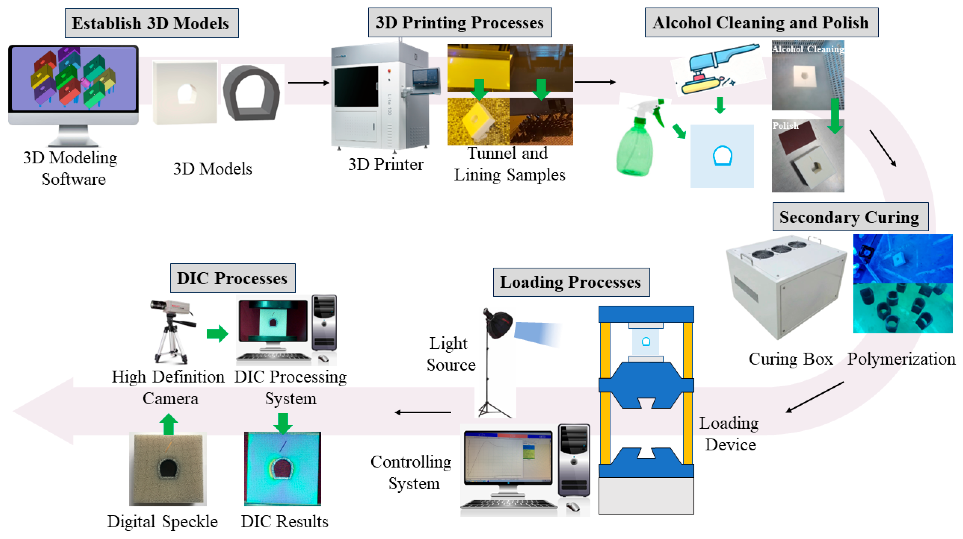
- Establish 3D models: Establish 3D models of tunnels and linings that meet the requirements through 3D modeling software (such as Catia).
- (2)
- 3D-printing processes: The established 3D modes (tunnel model and lining model) are imported into Lite3D printer; the tunnel and lining samples will be printed layer by layer.
- (3)
- Alcohol cleaning and polish: Remove the support of the printed sample, wash the excess liquid resin with alcohol, and polish the uneven surface of the sample with sandpaper.
- (4)
- Secondary curing: Put the polished tunnel and lining samples into the UV curing box to further cure and improve the brittleness of the samples.
- (5)
- Loading processes: Spray speckles on the surface of the tunnel and lining specimens, and put them into the uniaxial loading system after splice. Control the loading rate at 0.5 mm/min. Use the light source to fill light on the specimen surface, and the controlling system is used to monitor the stress and displacement changes during the loading processes.
- (6)
- DIC processes: The images of tunnel and lining samples are captured in real time, and the DIC systems are used to calculate the strain on the sample surfaces.
2.3. Schemes
3. Numerical Strategy for Simulating Material Failure
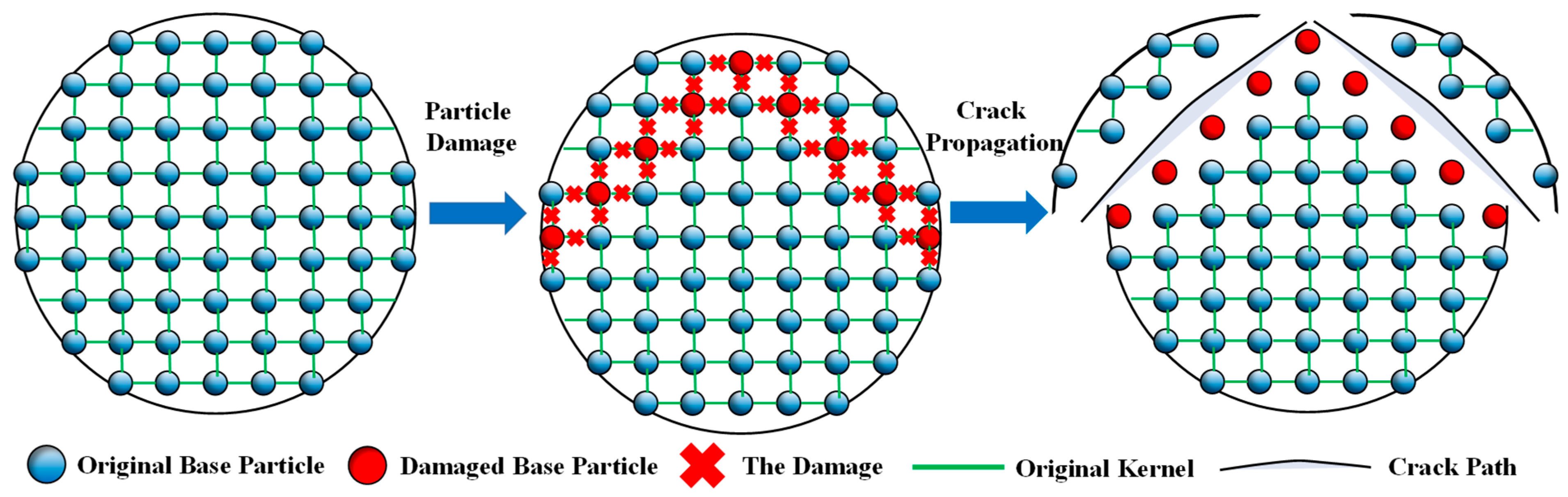
3.1. Numerical Treatments of Crack Propagation in SPH
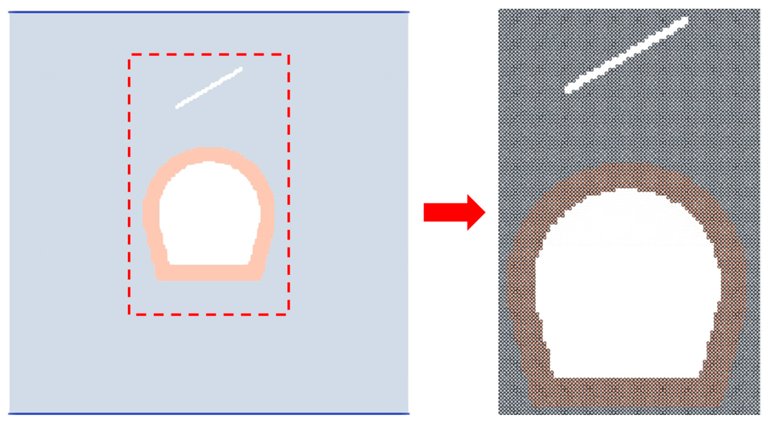
3.2. Model Dimension and Particle Divisions
4. Experimental and Numerical Results
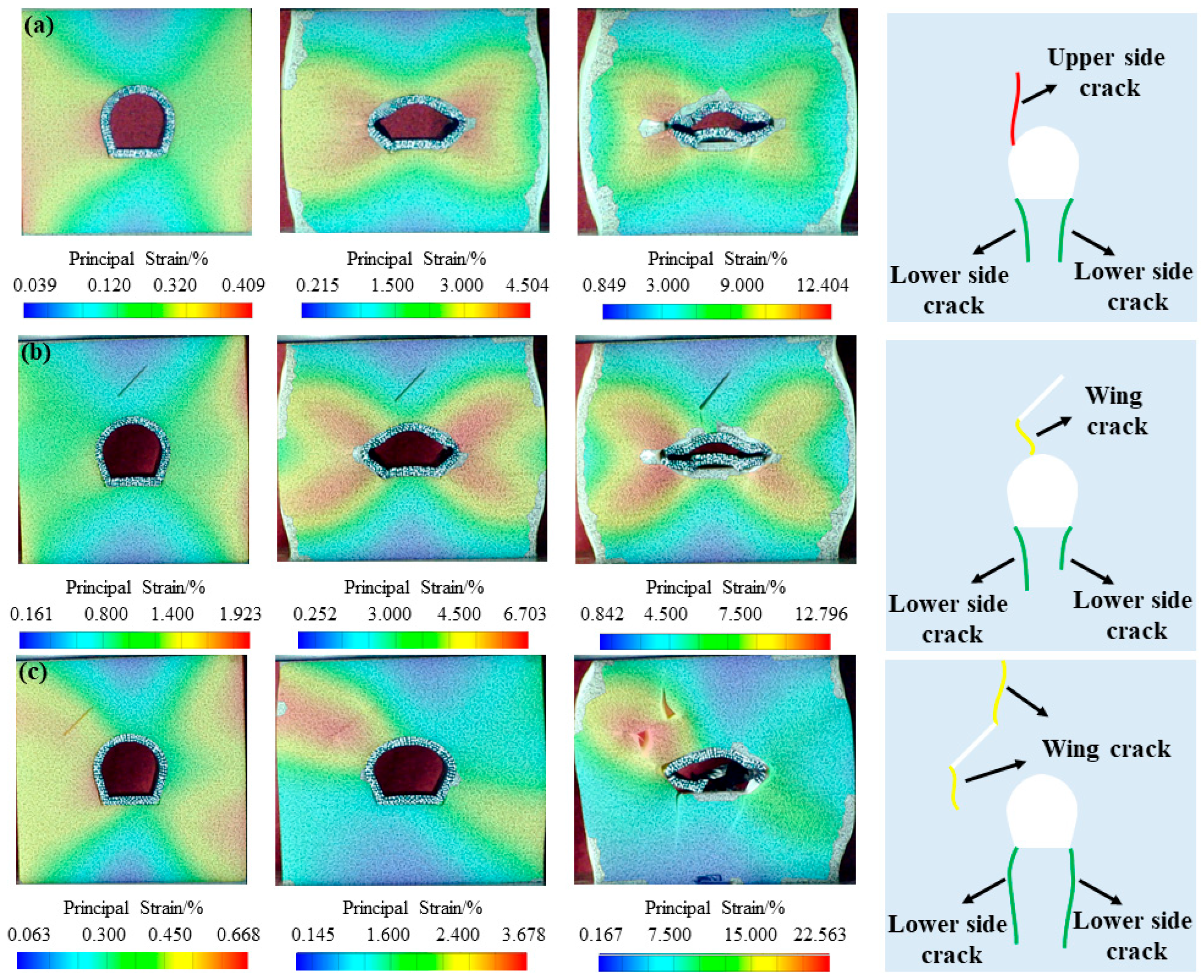
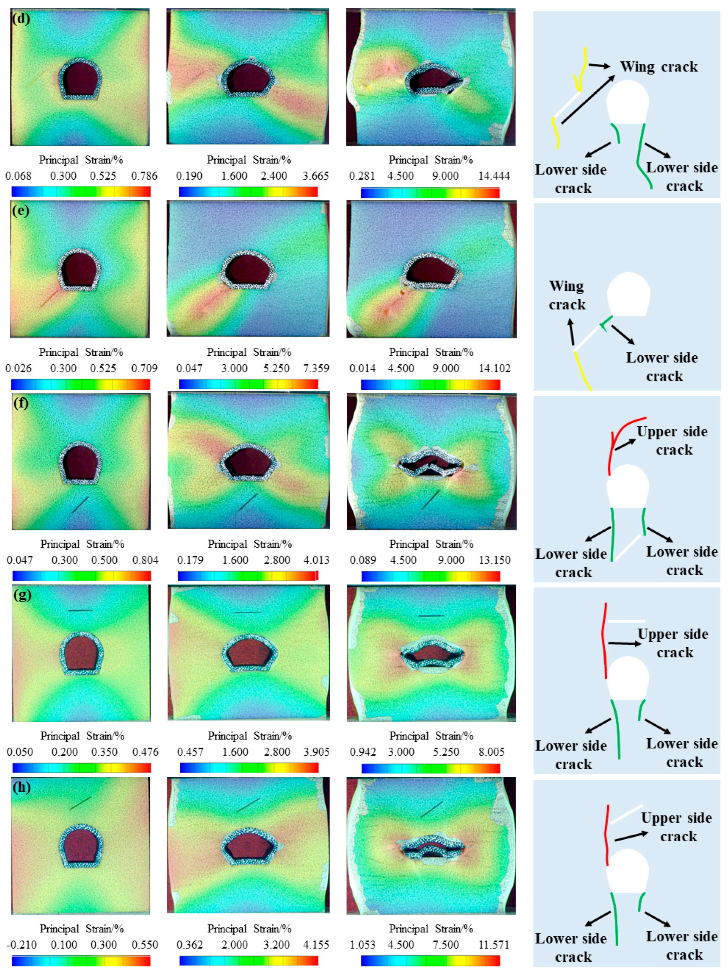
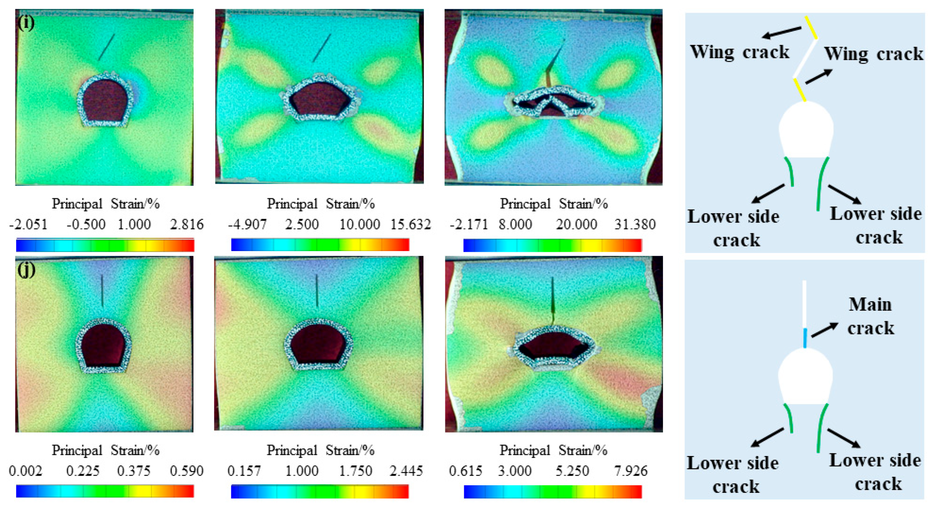
4.1. Crack Propagation of the Tunnel Structure
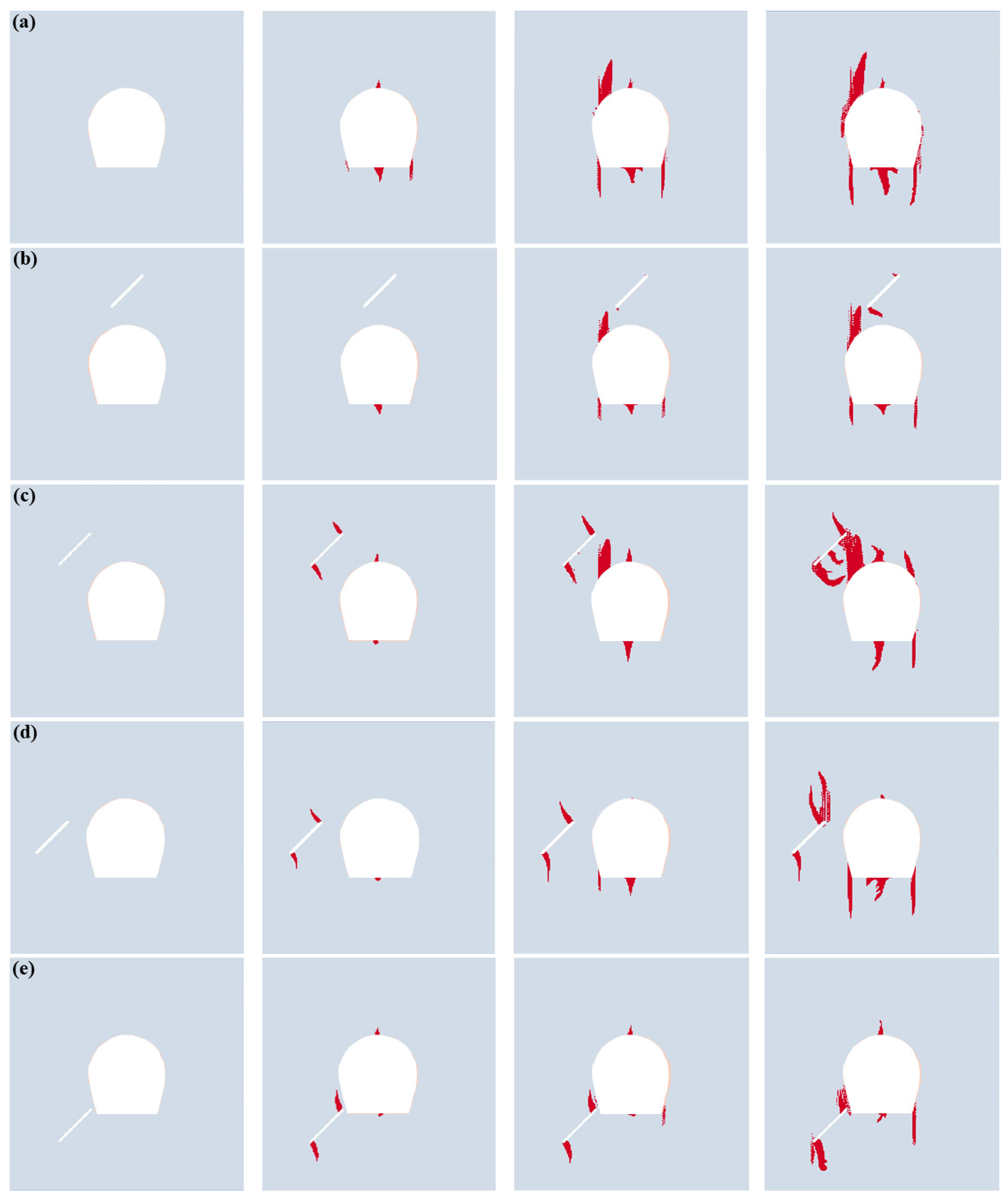
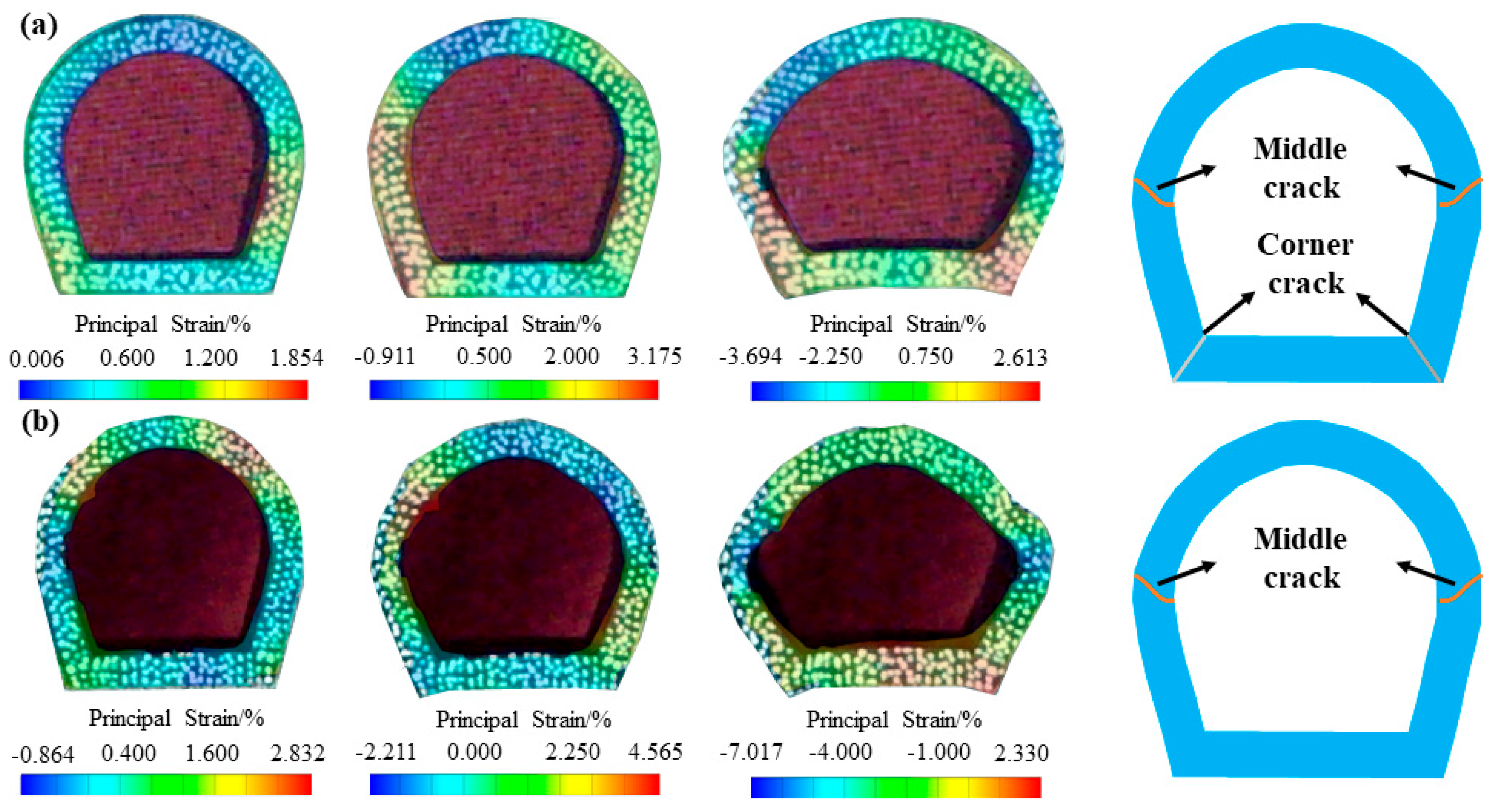
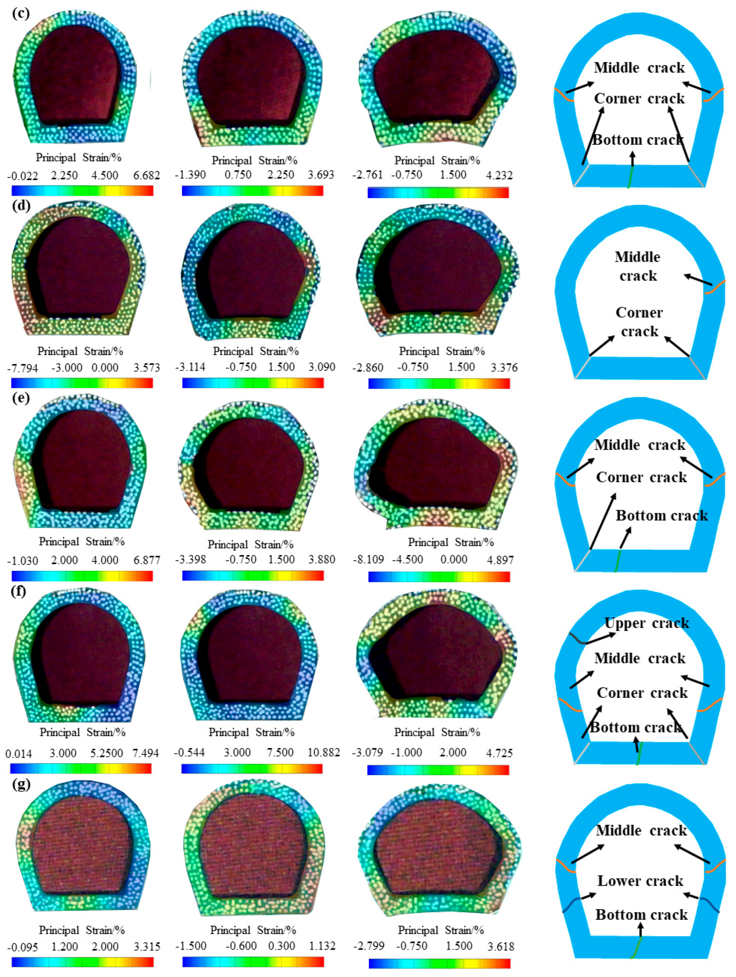
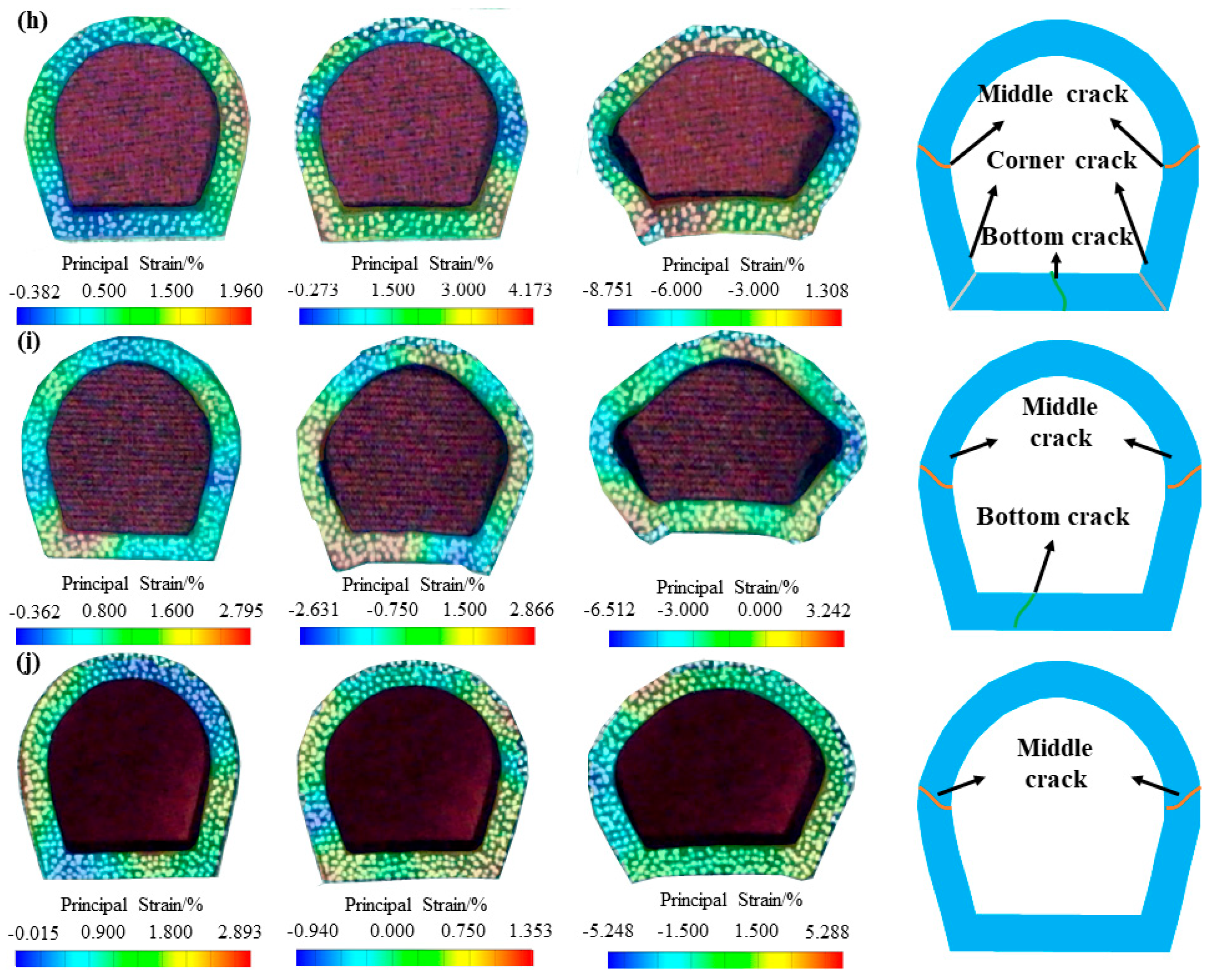
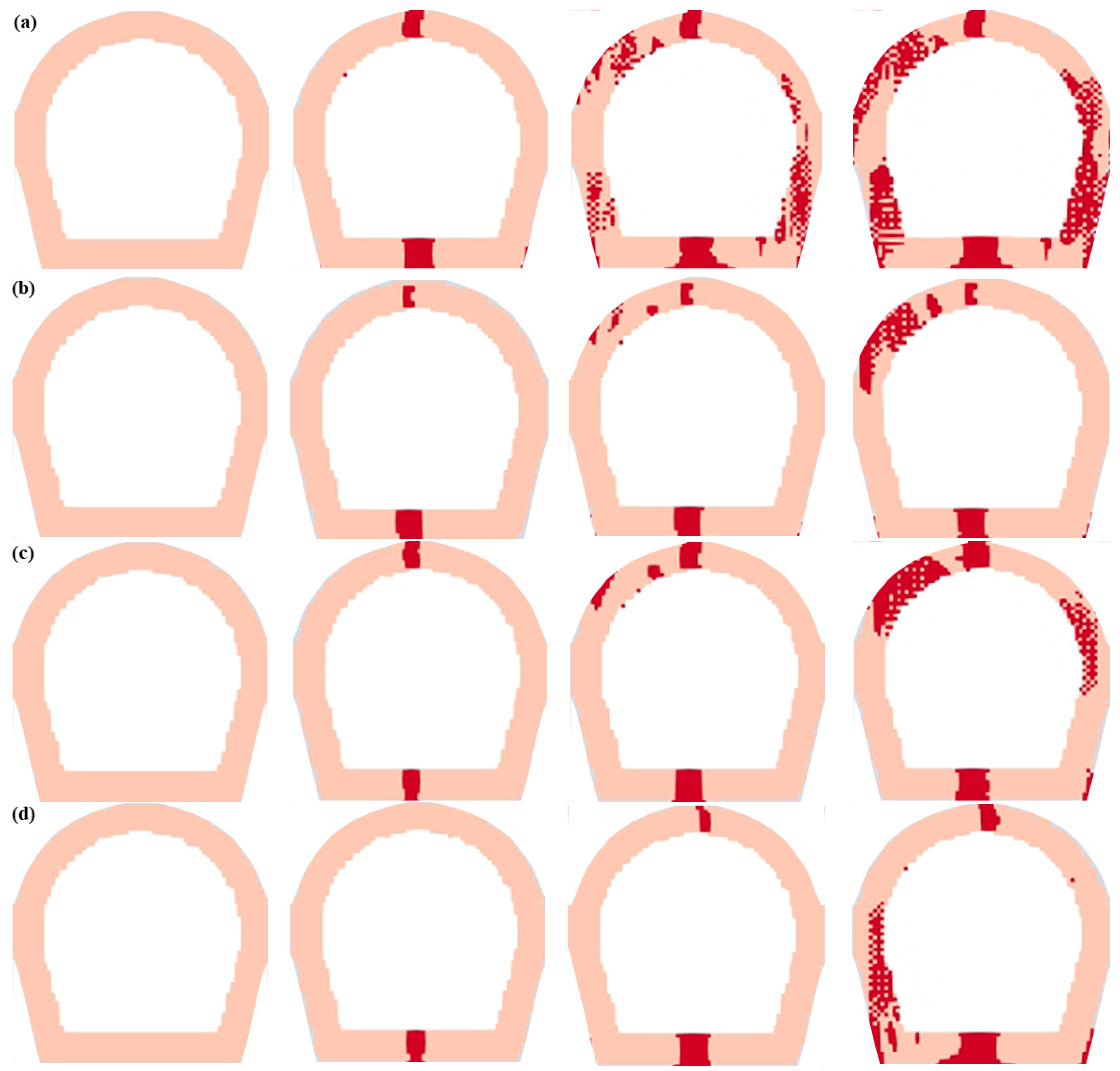
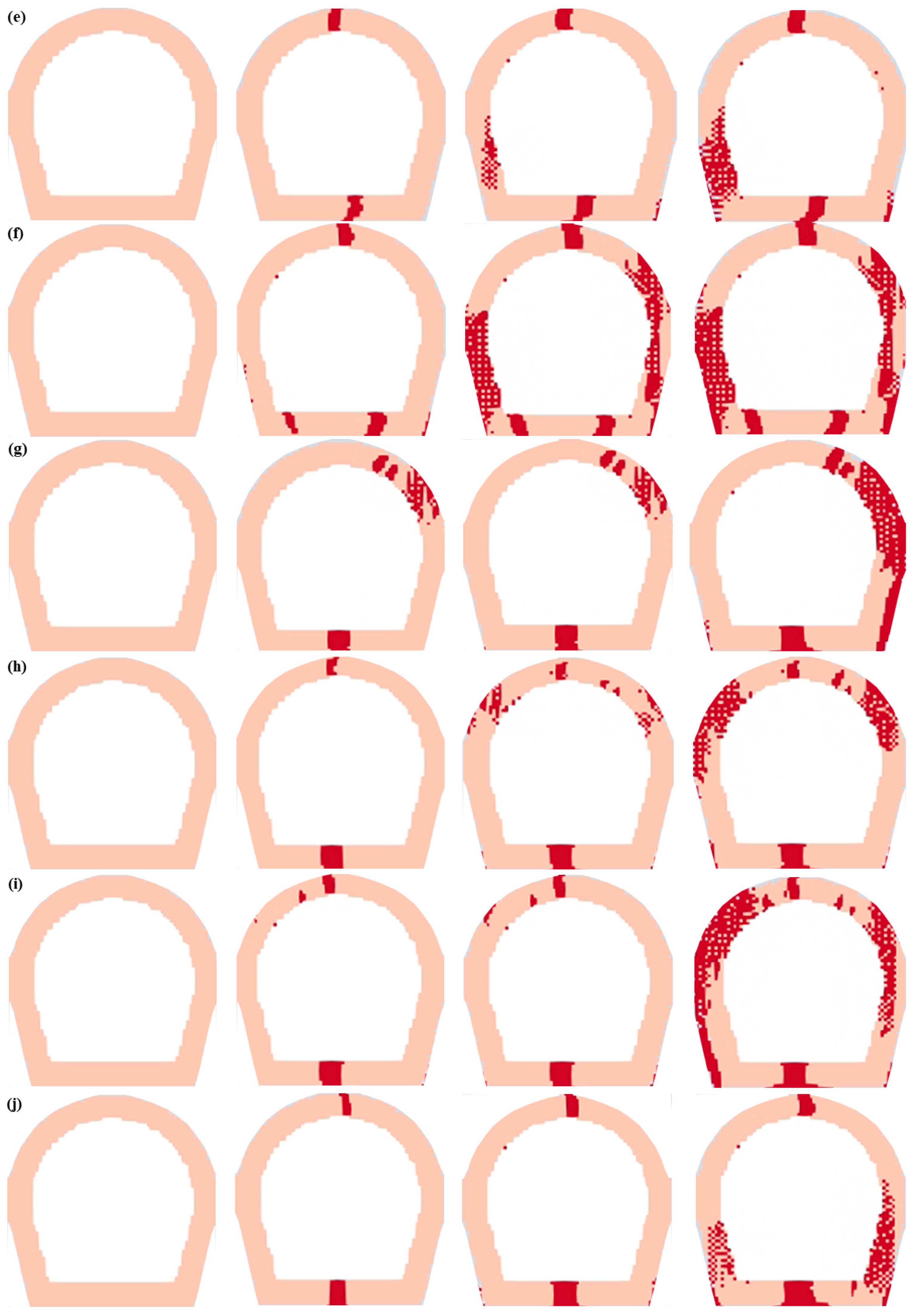
4.2. Crack Propagation Processes of the Lining Structure
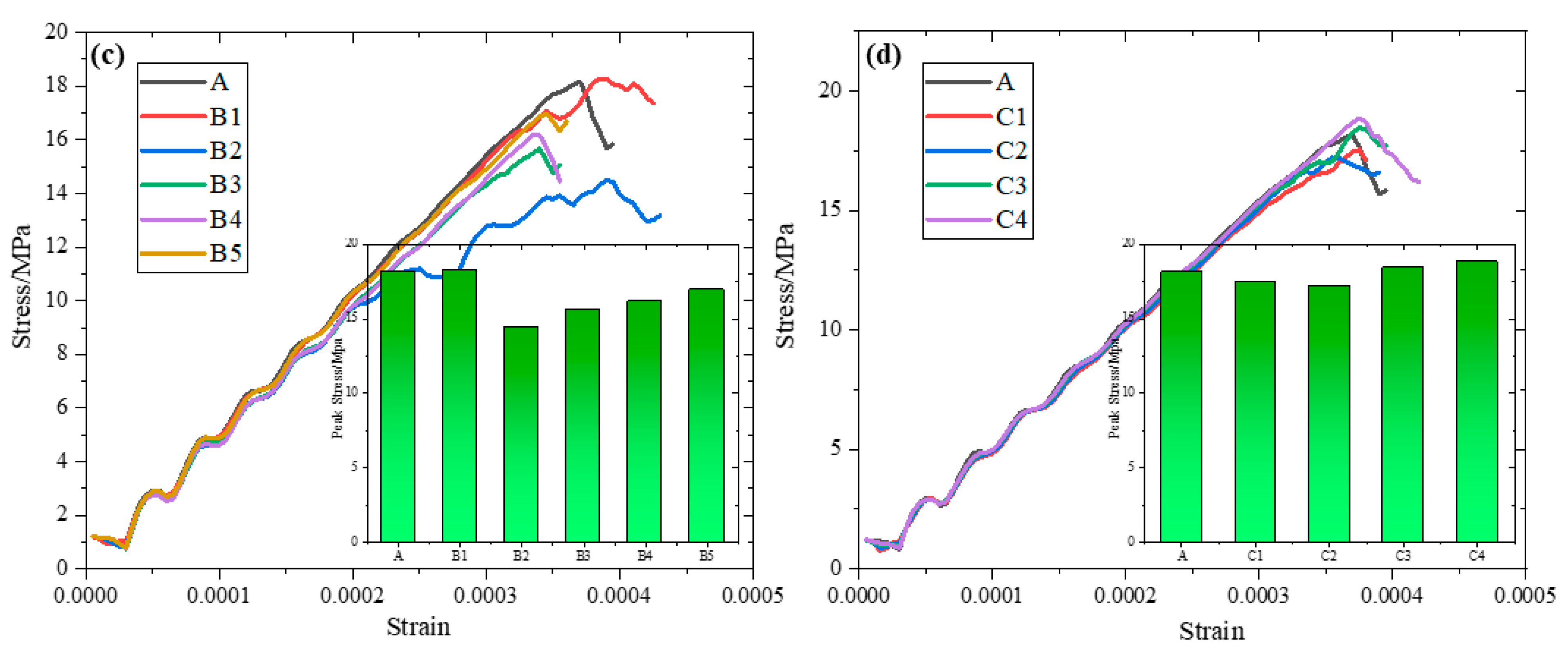
4.3. Influences of Fissure Inclination and Orientation Angles on Tunnel-Lining Structure Strength
5. Discussions on Cracking Mechanisms
5.1. Crack Initiation Mechanisms of Tunnel-Lining Structures in Scheme A
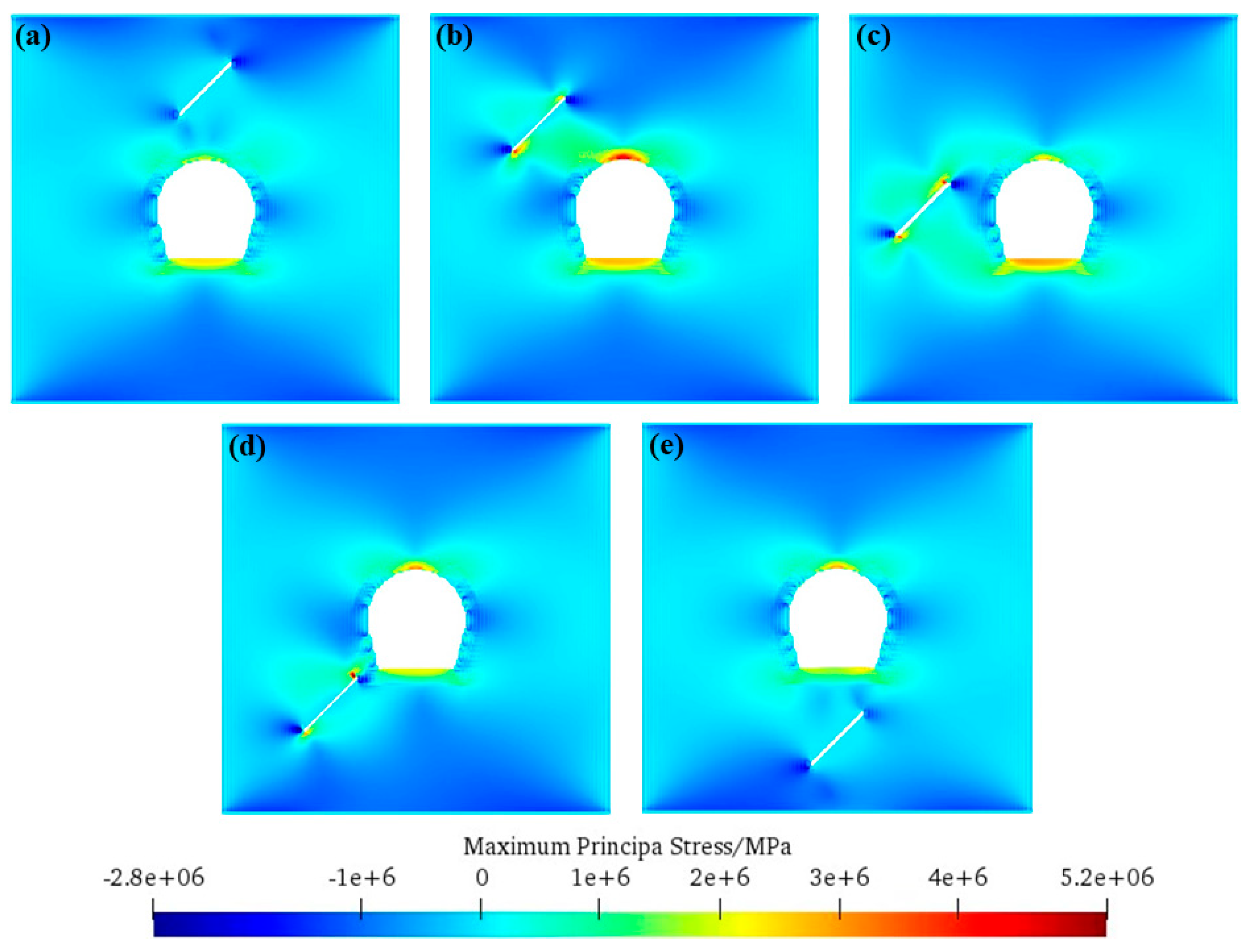
5.2. Crack Initiation Mechanisms of Tunnel-Lining Structures with Various Orientations
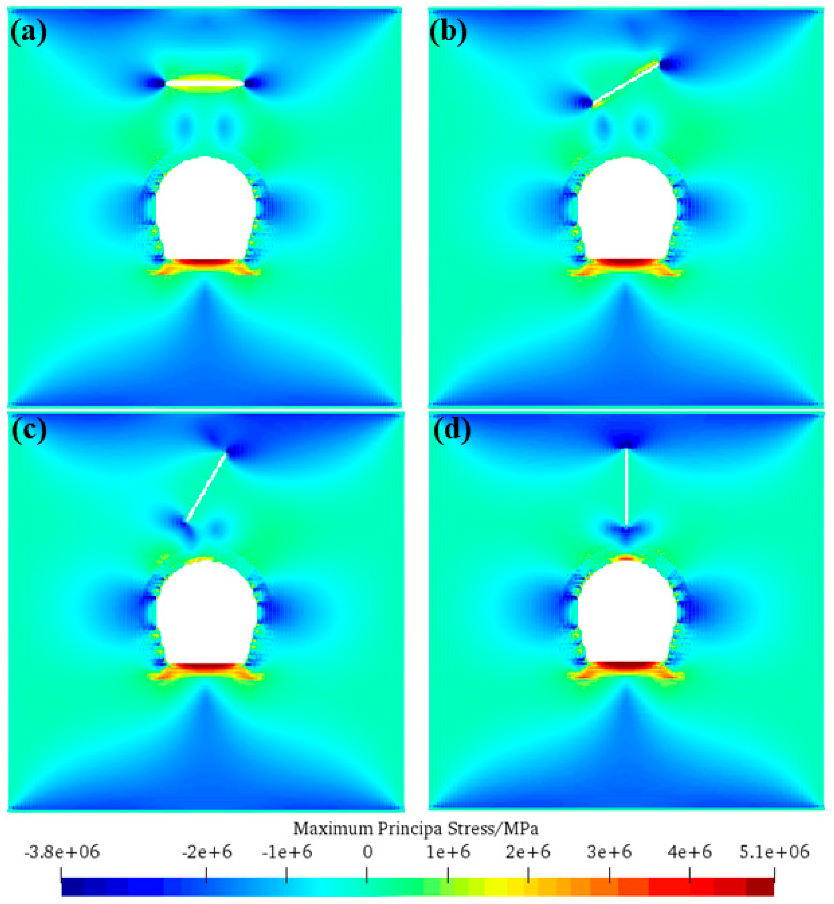
5.3. Crack Initiation Mechanisms of Tunnel-Lining Structures with Various Inclinations
5.4. Limitations of SPH Method for Simulating Crack Propagation
5.4.1. Neglecting the Rate Dependency and Time Effects
5.4.2. Simplified Treatment of Mixed-Mode Fracture
5.4.3. Lack of Plastic Deformation and Damage Evolution
5.4.4. Inadequate Representation of Material Heterogeneity
6. Conclusions
- (1)
- Uniaxial compression fracture tests of tunnel-lining structures containing prefabricated fissures are carried out based on 3D-printing technology and DIC technology, and the impacts of various fissure properties on the failure laws of tunnel-lining structures are explored.
- (2)
- Three types of cracks occur at tunnel sites, namely main crack, upper-side crack and lower-side crack.
- (3)
- Five types of cracks occur around the lining, namely upper crack, middle crack, lower crack, corner crack and bottom crack. When a wing crack propagation occurs in prefabricated fissures, the crack propagation degree around the lining is relatively small, while when wing cracks do not initiate from prefabricated fissures, more cracks are produced around the lining.
- (4)
- Crack initiation mechanisms of tunnel-lining structures under different schemes are discussed: The tension stress concentration at the bottom of the tunnel-lining structure is the cause of the bottom crack. After the initiation of the bottom crack, a stress concentration occurs at the tunnel’s upper and lower parts, which is the cause of the upper- and lower-side crack around the tunnel. When the fissure orientation angle β is close to 90°, tensile stress concentrations are larger, contributing to wing crack extensions prior to the crack propagation in tunnel-lining structures.
Author Contributions
Funding
Data Availability Statement
Conflicts of Interest
References
- Zhu, Y.; Zhou, J.; Zhang, B. Statistical analysis of major tunnel construction accidents in China from 2010 to 2020. Tunn. Undergr. Space Technol. 2022, 124, 104460. [Google Scholar] [CrossRef]
- Sun, W.; Lin, E.; Yang, Z. Damage analysis of buried pipelines subjected to side-by-side twin tunneling based on centrifuge and numerical modeling. Tunn. Undergr. Space Technol. 2024, 146, 105647. [Google Scholar] [CrossRef]
- Sun, Z.; Zhang, D.; Wang, J. Analytical approach for the design of composite linings in deep tunnels considering the blasting damaged zone. Tunn. Undergr. Space Technol. 2024, 147, 105695. [Google Scholar] [CrossRef]
- Jiao, P. Study on Failure Mechanism of Lining Structure of Mountain Tunnel Caused by Dislocation of Fault; Shandong University: Shandong, China, 2024. [Google Scholar]
- Zheng, X. Evolution Law of Lining Cracking and Frost Heaving Pressure of Water-Rich Tunnel Surrounding Rock in Cold Regions; Shandong University: Shandong, China, 2023. [Google Scholar]
- He, B.; Xue, R.; Zhang, Z. A novel method of imposing external water pressure to explore the failure behavior of railway tunnel linings. Tunn. Undergr. Space Technol. 2023, 133, 104942. [Google Scholar] [CrossRef]
- Wang, Z.; Jiang, Y.; Zhu, C. Shaking table tests of tunnel linings in progressive states of damage. Tunn. Undergr. Space Technol. 2015, 50, 109–117. [Google Scholar] [CrossRef]
- Huang, H.; Liu, D.; Xue, Y. Numerical analysis of cracking of tunnel linings based on extended finite element. Chin. J. Geotech. Eng. 2013, 35, 266–275. [Google Scholar]
- Wang, Z.; Zhong, Z.; Zhao, M. Simulation of normal fault rupture and its impact on mountain tunnels. Chin. J. Geotech. Eng. 2020, 42, 1876–1884. [Google Scholar]
- Liu, Y.; Lai, J.; Xin, J. Comparison test of dynamic response characteristics of the tunnels through fault. Rock Soil Mech. 2019, 40, 4693–4702. [Google Scholar]
- Liu, X.; Wang, X.; Lin, L. Model experiment on effect of normal fault with 75°dip angle stick-slip dislocation on highway tunnel. Chin. J. Rock Mech. Eng. 2013, 32, 1714–1720. [Google Scholar]
- Zhang, Z.; Chen, B.; Li, H. The performance of mechanical characteristics and failure mode for tunnel concrete lining structure in water-rich layer. Tunn. Undergr. Space Technol. 2022, 121, 104335. [Google Scholar] [CrossRef]
- Wang, H.; Liu, X.; Li, N. Safety evaluation of tunnel lining with longitudinal cracks and reinforcement design. Chin. J. Rock Mech. Eng. 2010, 29, 2651–2656. [Google Scholar]
- Zhu, Z.; Yang, L.; Xu, N. Elastic-plastic Damage Model Establishment and Application Study of Tunnel Lining. J. Railw. Eng. Soc. 2018, 35, 72–79. [Google Scholar]
- Wen, Q.; Qin, W. Study on Seepage-stress-failure Coupling Model for Tunnel Lining with High Water Pressure. J. Railw. Eng. Soc. 2013, 30, 63–68. [Google Scholar]
- Bian, K.; Xiao, M. Seepage-damage-stress coupling analysis of hydraulic tunnel lining in hydraulic fracturing process. Chin. J. Rock Mech. Eng. 2010, 29, 3769–3776. [Google Scholar]
- Asgari, A.; Ranjbar, F.; Bagheri, M. Seismic resilience of pile groups to lateral spreading in liquefiable soils: 3D parallel finite element modeling. Structures 2025, 74, 108578. [Google Scholar] [CrossRef]
- Liu, C.; Peng, Z.; Cui, J. Development of crack and damage in shield tunnel lining under seismic loading: Refined 3D finite element modeling and analyses. Thin-Walled Struct. 2023, 185, 110647. [Google Scholar] [CrossRef]
- Liu, X.; Zhuang, Y.; Zhou, X. Numerical study of the mechanical process of long-distance replacement of the definitive lining in severely damaged highway tunnels. Undergr. Space 2023, 9, 200–217. [Google Scholar] [CrossRef]
- Fan, X.; Yang, Z.; Li, K. Effects of the lining structure on mechanical and fracturing behaviors of four-arc shaped tunnels in a jointed rock mass under uniaxial compression. Theor. Appl. Fract. Mech. 2021, 112, 102887. [Google Scholar] [CrossRef]
- Yang, H.; Xu, J.; Zhang, K. Study on generation and evolution of base voids in heavy-haul railway tunnels using particle flow method. Tunn. Undergr. Space Technol. 2024, 145, 105569. [Google Scholar] [CrossRef]
- Wang, Y.; Zhou, X.; Shou, Y. The modeling of crack propagation and coalescence in rocks under uniaxial compression using the novel conjugated bond-based peridynamics. Int. J. Mech. Sci. 2017, 128, 614–643. [Google Scholar] [CrossRef]
- Wang, Y.; Zhou, X.; Yuan, W. A 3-D conjugated bond-pair-based peridynamic formulation for initiation and propagation of cracks in brittle solids. Int. J. Solids Struct. 2018, 134, 89–115. [Google Scholar] [CrossRef]
- Zhou, X.; Du, E.; Wang, Y. Thermo-hydro-chemo-mechanical coupling peridynamic model of fractured rock mass and its application in geothermal extraction. Comput. Geotech. 2022, 148, 104837. [Google Scholar] [CrossRef]
- Yan, P.; Ren, B.; Cai, Y. Numerical modeling techniques for shield tunnel lining structure using the numerical manifold method (NMM). Eng. Anal. Bound. Elem. 2024, 162, 363–374. [Google Scholar] [CrossRef]
- Fan, H.; Huang, D.; Wang, G. A four-way enhanced numerical manifold method for crack propagation and failure analysis of rock slopes. Appl. Math. Model. 2021, 95, 623–643. [Google Scholar] [CrossRef]
- Baktheer, A.; Martínez-Pañeda, E.; Aldakheel, F. Phase field cohesive zone modeling for fatigue crack propagation in quasi-brittle materials. Comput. Methods Appl. Mech. Eng. 2024, 422, 116834. [Google Scholar] [CrossRef]
- Zhou, C.; He, J.; Berggreen, C. A combined interface phase field (CIPF) model for interfacial crack propagation. Eng. Fract. Mech. 2024, 295, 109779. [Google Scholar] [CrossRef]
- Zhou, X.; Zhao, Y.; Qian, Q. Smooth particle hydrodynamic numerical simulation of rock failure under uniaxial compression. Chin. J. Rock Mech. Eng. 2015, 34, 2647–2658. [Google Scholar]
- Zhao, Y.; Zhou, X.; Qian, Q. Progressive failure processes of reinforced slopes based on general particle dynamic method. J. Cent. South Univ. 2015, 22, 4049–4055. [Google Scholar] [CrossRef]
- Zhou, X.; Zhao, Y.; Qian, Q. A novel meshless numerical method for modeling progressive failure processes of slopes. Eng. Geol. 2015, 192, 139–153. [Google Scholar] [CrossRef]
- Bi, J. The Fracture Mechanisms of Rock Mass Under Stress, Seepage, Temperature and Damage Coupling Condition and Numerical Simulations by Using the General Particle Dynamics (GPD) Algorithm; Chongqing University: Chongqing, China, 2016. [Google Scholar]
- Bi, J.; Zhou, X. A Novel Numerical Algorithm for Simulation of Initiation, Propagation and Coalescence of Flaws Subject to Internal Fluid Pressure and Vertical Stress in the Framework of General Particle Dynamics. Rock Mech. Rock Eng. 2017, 50, 1833–1849. [Google Scholar] [CrossRef]
- Bi, J.; Zhou, X.; Qian, Q. The 3D Numerical Simulation for the Propagation Process of Multiple Pre-existing Flaws in Rock-Like Materials Subjected to Biaxial Compressive Loads. Rock Mech. Rock Eng. 2016, 49, 1611–1627. [Google Scholar] [CrossRef]
- Bi, J.; Zhou, X. Numerical Simulation of Zonal Disintegration of the Surrounding Rock Masses Around a Deep Circular Tunnel Under Dynamic Unloading. Int. J. Comput. Methods 2015, 12, 1550020. [Google Scholar] [CrossRef]
- Zhou, X.; Bi, J.; Qian, Q. Numerical Simulation of Crack Growth and Coalescence in Rock-Like Materials Containing Multiple Pre-existing Flaws. Rock Mech. Rock Eng. 2015, 48, 1097–1114. [Google Scholar] [CrossRef]
- Zhou, X.; Bi, J. 3D Numerical Study on the Growth and Coalescence of Pre-existing Flaws in Rocklike Materials Subjected to Uniaxial Compression. Int. J. Geomech. 2016, 16, 04015096. [Google Scholar] [CrossRef]
- Chai, J.; Ouyang, Y.; Liu, J. Improved virtual extensometer measurement method in complex multi-fracture situation. Sci. Rep. 2022, 12, 6819. [Google Scholar] [CrossRef]
- Yu, S.; Wang, J.; Gao, Y. Effects of fissure properties on the tunnel damage evolutions: Insights from DIC-based 3D printing experiments and meshless numerical simulations. Tunn. Undergr. Space Technol. 2024, 149, 105817. [Google Scholar] [CrossRef]
- Yang, S.; Chen, R. A new strategy for 3D non-persistent crack propagation by the numerical manifold method with tetrahedral meshes. Eng. Anal. Bound. Elem. 2023, 148, 190–204. [Google Scholar] [CrossRef]


| Specimen Sizes with No Fissures | Specimen Sizes Containing Fissures |
 |  |
| Specimen Number | Experimental Schemes | Specimen Number | Experimental Schemes |
|---|---|---|---|
| A | No fissures | B5 | β = 180° |
| B1 | β = 0° | C1 | α = 0° |
| B2 | β = 45° | C2 | α = 30° |
| B3 | β = 90° | C3 | α = 60° |
| B4 | β = 135° | C4 | α = 90° |
Disclaimer/Publisher’s Note: The statements, opinions and data contained in all publications are solely those of the individual author(s) and contributor(s) and not of MDPI and/or the editor(s). MDPI and/or the editor(s) disclaim responsibility for any injury to people or property resulting from any ideas, methods, instructions or products referred to in the content. |
© 2025 by the authors. Licensee MDPI, Basel, Switzerland. This article is an open access article distributed under the terms and conditions of the Creative Commons Attribution (CC BY) license (https://creativecommons.org/licenses/by/4.0/).
Share and Cite
Yu, S.; Chen, Z.; Li, Y.; Li, W.; Zhang, B. Three-Dimensional Printing Experiments and Particle-Based Meshless Numerical Investigations on the Failure Modes of Tunnel-Lining Structures Containing Fissures. Buildings 2025, 15, 2136. https://doi.org/10.3390/buildings15122136
Yu S, Chen Z, Li Y, Li W, Zhang B. Three-Dimensional Printing Experiments and Particle-Based Meshless Numerical Investigations on the Failure Modes of Tunnel-Lining Structures Containing Fissures. Buildings. 2025; 15(12):2136. https://doi.org/10.3390/buildings15122136
Chicago/Turabian StyleYu, Shuyang, Zhongqing Chen, Yifei Li, Wei Li, and Bufan Zhang. 2025. "Three-Dimensional Printing Experiments and Particle-Based Meshless Numerical Investigations on the Failure Modes of Tunnel-Lining Structures Containing Fissures" Buildings 15, no. 12: 2136. https://doi.org/10.3390/buildings15122136
APA StyleYu, S., Chen, Z., Li, Y., Li, W., & Zhang, B. (2025). Three-Dimensional Printing Experiments and Particle-Based Meshless Numerical Investigations on the Failure Modes of Tunnel-Lining Structures Containing Fissures. Buildings, 15(12), 2136. https://doi.org/10.3390/buildings15122136