Article

Safety Risk Assessment of Double-Line Tunnel Crossings Beneath Existing Tunnels in Complex Strata

1
Nanning Rail Transit Co., Ltd., Nanning 530029, China
2
School of Resources and Safety Engineering, Central South University, Changsha 410083, China
3
School of Civil Engineering, Changsha University of Science and Technology, Changsha 410114, China
*
Author to whom correspondence should be addressed.
Buildings 2025, 15(12), 2103; https://doi.org/10.3390/buildings15122103
Submission received: 22 April 2025 / Revised: 4 June 2025 / Accepted: 11 June 2025 / Published: 17 June 2025
(This article belongs to the Special Issue Structural Analysis of Underground Space Construction)

Abstract

:
With the acceleration of urbanization, the development of urban rail transit networks has become an essential component of modern urban transportation. The construction of new urban rail transit lines often involves crossing existing operational lines, posing significant safety risks and technical challenges. This paper presents a comprehensive study on the safety risk assessment and control measures for the construction of new double-line shield tunnels crossing beneath existing tunnels in complex strata, using the project of Line 5 of the Nanning Urban Rail Transit crossing beneath the existing Line 2 interval tunnel as a case study. This study employs methods such as status investigation, numerical simulation, and field measurement to analyze the construction risks. Key findings include the successful identification and control of major risk sources through refined risk assessment and comprehensive technical measurement. The maximum settlement of the existing tunnel was effectively controlled at −2.55 mm, well within the deformation monitoring control values. This study demonstrates that optimized shield machine selection, improved lining design, interlayer soil reinforcement, the dynamic adjustment of shield parameters, and the precise measurement of shield posture significantly enhance the efficiency of shield tunneling and construction safety. The results provide a valuable reference for the settlement and deformation control of similar projects.

1. Introduction

With the acceleration of urbanization, the development of urban rail transit networks has become an essential component of modern urban transportation. The construction of new urban rail transit lines may involve crossing existing operational lines, posing significant safety risks and technical challenges [1,2,3,4]. Particularly under conditions of small clearance—when new tunnels are constructed in close proximity beneath existing ones—the construction environment can become extremely complex and hazardous. If the construction of the new tunnel is not properly controlled, it can easily induce abnormal deformation and structural damage to the existing tunnel, thereby affecting the safe operation of the existing line [5,6,7]. In severe cases, this may even lead to casualties and property losses. Therefore, effectively controlling the safety risks associated with the construction of new tunnels crossing beneath existing tunnels has become a core issue in urban rail transit engineering [8,9,10,11]. Gan, Yu [12] proposed a simplified two-stage analysis method to study the longitudinal response of existing tunnels with discontinuous structural stiffness to new tunnel construction and explored the influence of various factors on tunnel response. Liu, Li [13] established an internal force calculation model for a horseshoe-shaped tunnel and analyzed the impact of the construction of a new station on Line 12 of the Beijing Subway crossing beneath the existing Line 5, proposing suggestions for optimizing construction parameters. However, there is still a lack of in-depth analysis combining specific safety risk control measures with the actual construction process of crossings beneath tunnels. In terms of numerical simulation, three-dimensional finite element software has been widely used to predict the stress and deformation effects of shield tunnel construction on existing tunnels [14,15,16,17]. Yang, Zhang [18] analyzed the impact of river channel and bridge construction near Line 1 of the Changzhou Metro on existing double-line shield tunnels using three-dimensional numerical simulation and field monitoring, proposing a comprehensive protection plan. In terms of construction technology, measures such as shield machine selection, lining design, interlayer soil reinforcement, and shield parameter optimization have been proven to be effective in controlling settlement and deformation [19,20]. For example, air cushion slurry balance shield machines can effectively reduce ground settlement by precisely controlling the face pressure. Moreover, reasonable tool configuration, shield posture measurement, and the application of real-time monitoring and early warning systems also provide security for shield construction. Zhang, Liu [21] analyzed the vehicle-induced dynamic response characteristics of the existing line during the construction of Line 8 of the Chengdu Metro crossing beneath the existing Line 1 through field testing and numerical calculations. Huang, Wang [22] studied the punching shear failure mode of the pile-end-bearing stratum during shield tunneling beneath existing piles using reduced-scale model tests and PIV technology, constructing a theoretical failure mechanism based on a limit analysis. Chen, Liu [23] proposed a hybrid intelligent framework based on interpretable machine learning and multi-objective optimization for controlling the deformation of existing tunnels caused by shield tunneling beneath existing tunnels. Despite significant progress in existing research, the further optimization of shield construction parameters to enhance the safety of existing tunnels remains a current research hotspot and challenge [24,25,26,27,28]. Particularly under extreme conditions such as small clearance, large span, and complex strata, how to achieve safe crossing of shield tunnels still requires in-depth exploration.
This study, based on the project of Line 5 of the Nanning Urban Rail Transit crossing beneath the existing Line 2 interval tunnel, aims to address the critical issue of the safety risk assessment and control for such complex crossing projects by employing methods such as status investigation, numerical simulation, and field measurement. Through the implementation of comprehensive technical measures such as shield machine selection, lining design improvement, interlayer soil reinforcement, shield parameter optimization, and shield posture measurement, the construction parameters of the shield tunneling were dynamically adjusted, enabling the successful crossing of the new tunnel and ensuring the safe operation of the existing line.

2. Project Overview and Geological Conditions

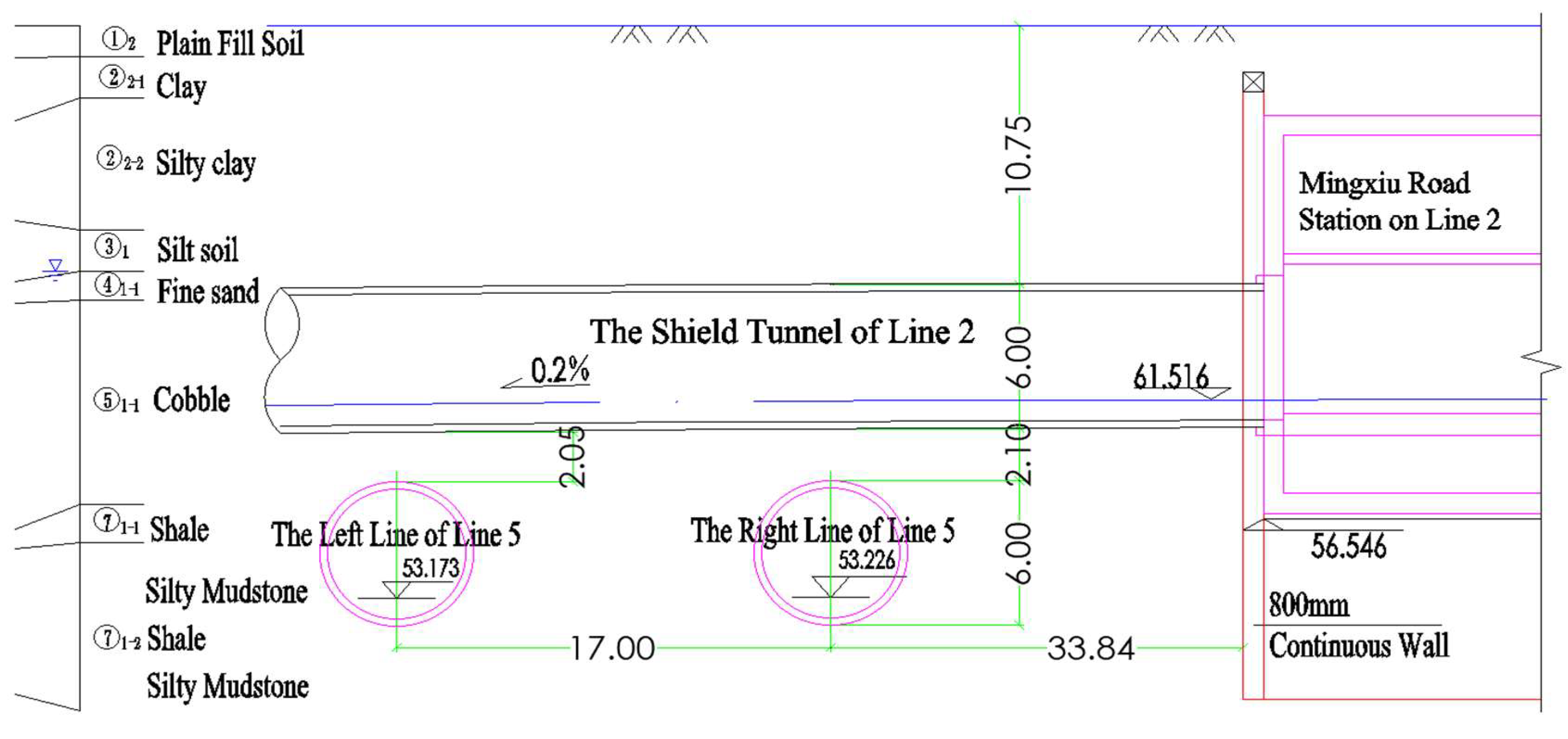
2.1. Project Overview

The construction of Line 5 of the Nanning Urban Rail Transit crossing beneath the existing Line 2 interval tunnel is a typical example of such complex crossing projects. Located at the busy intersection of Youai Road and Mingxiu Road, the project is characterized by dense underground utilities and a complex surrounding environment. The existing Line 2 tunnel has a soil cover thickness of approximately 10.75 m, while the Line 5 tunnel has a soil cover thickness of about 18.8 m. The vertical clearance between the upper and lower tunnels ranges from 2.05 m to 2.10 m, making the construction extremely challenging. Additionally, the geological conditions of the crossing section are complex, which increases the difficulty of shield tunneling control, as shown in Figure 1. Both Line 2 and Line 5 shield tunnel sections have a lining ring outer diameter of 6.0 m, an inner diameter of 5.4 m, and a lining thickness of 0.3 m. The lining ring width is 1.5 m, and each ring consists of one cap block, two adjacent blocks, and three standard blocks. The lining concrete is designed with a strength of C50 and a water resistance grade of P12. The non-crossing section uses Type X-3 lining, while the crossing section uses Type X-4 lining. Since the minimum clearance between the newly constructed Line 5 and the existing Line 2 tunnel is about 2.0 m, the close proximity relationship is very evident; the interlayer soil between the two tunnel lines is entirely composed of water-bearing gravel; the upper half of the excavation section of Line 5 crossing beneath Line 2 tunnel is gravel, while the lower half is mudstone, forming a typical “soft-over-hard” stratum characterized by the upper gravel layer (a relatively harder material) overlying the lower mudstone layer (a softer material), which increases the difficulty of shield tunneling control.

2.2. Geological Conditions

The main strata of the crossing section, from top to bottom, are as follows: plain fill soil ① 2, silty clay ② 3-2, silt ③ 1, fine sand ④ 1-1, gravel ⑤ 1-1, and mudstone ⑦ 1-3. The Line 5 shield tunnel body is mainly located in the mudstone stratum, with the crown in the gravel stratum; the Line 2 shield tunnel body is mainly located in the gravel stratum, with the crown in the silt. As shown in Figure 2, the main types of groundwater in the site are upper layer stagnant water and pore water in loose rocks. The pore water in loose rocks is mainly stored in the gravel stratum, with abundant water quantity, replenished by atmospheric precipitation and underground runoff, and in hydraulic connection with the Yongjiang River, forming a mutually replenishing relationship. During the survey period, the initial water level burial depth was 8.80–13.00 m, mostly appearing at the bottom of silt or the top of sand layers; the stable water burial depth is 8.50–10.50 m, with a hydraulic gradient of about 0.17%, and the water level fluctuation amplitude is about 3.0–5.0 m.

3. Safety Assessment of the Existing Tunnel

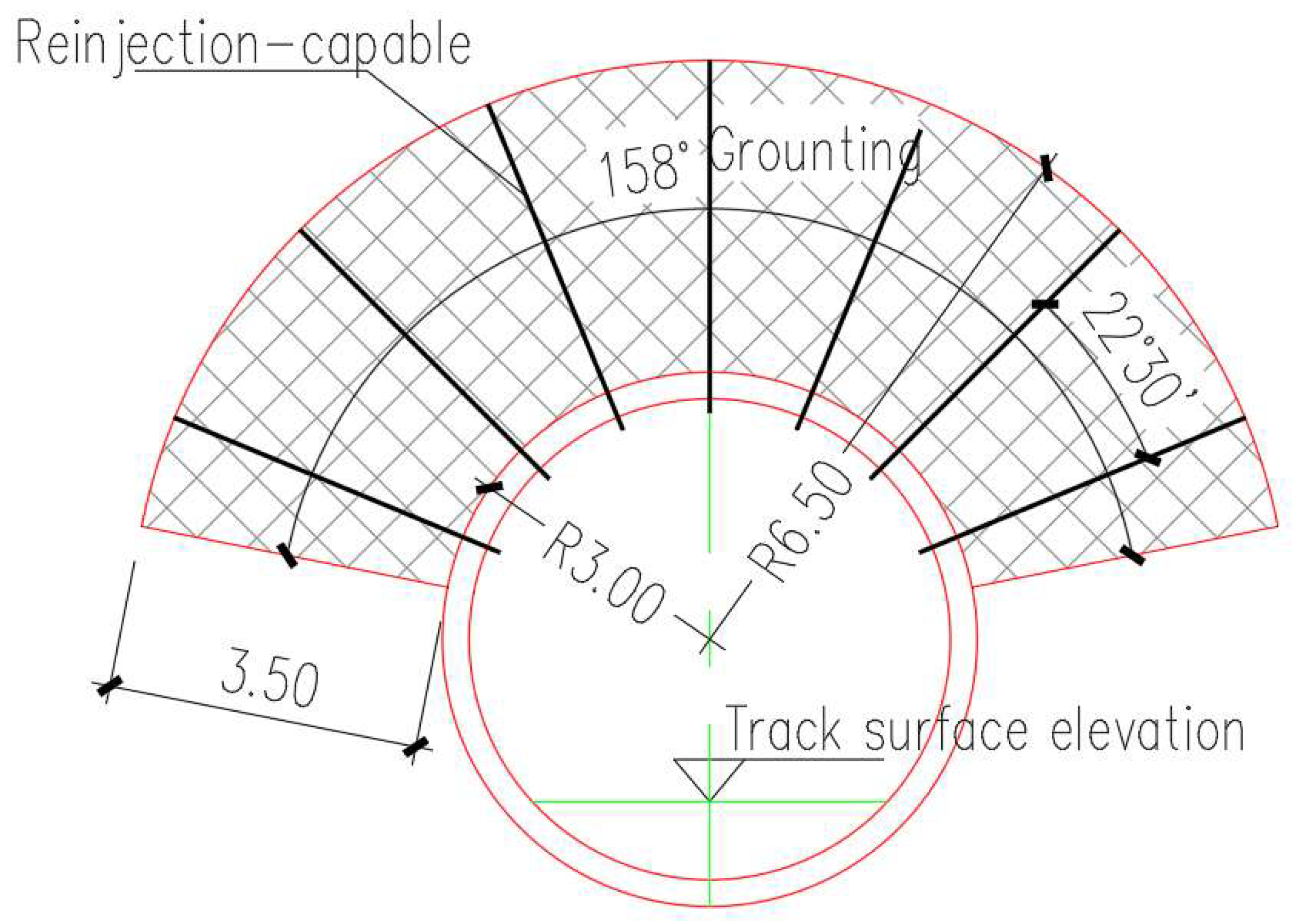
3.1. Reinforcement Methods for the Existing Tunnel

Field investigations revealed cracking and seepage issues in the track area of the existing line, with some tunnel segments exhibiting signs of dampness, cracking, and minor damage at the joints, although these do not currently compromise the structural safety of the existing tunnel. During the construction of the new tunnel crossing beneath the existing one, the existing tunnel structure may face several risks [29,30]. Firstly, the ground disturbance caused by the shield machine during tunneling can lead to additional deformation in the existing tunnel, thereby affecting its structural stability. Secondly, the construction of the new tunnel may alter the stress field surrounding the existing tunnel, causing a redistribution of internal forces within the existing tunnel structure and increasing the risk of structural damage. Moreover, complex geological conditions, such as water-bearing gravel and mudstone layers, further increase the uncertainty and risk associated with the construction. Therefore, reinforcing the existing tunnel can effectively enhance its structural stiffness and stability, reduce the disturbance caused by the construction process, and ensure the safety of both the construction and operation.
Grouting reinforcement within the tunnel is a key measure to improve the structural stiffness and stability of the existing tunnel. The grouting reinforcement range for the existing tunnel is 60 m in length. The grouting material primarily consists of a composite slurry with added admixtures, mainly composed of cement, sodium silicate, and anti-dispersion admixtures to enhance the stability and anti-dispersion properties of the slurry. The main design parameters for the grouting reinforcement are as follows: (1) the grouting slurry is primarily a composite type, with cement–sodium-silicate double-liquid slurry as a secondary option; (2) the grouting pipe is a Φ32 mm (t = 3.5 mm) sleeve valve pipe, with hole drilling carried out using a casing drilling rig; (3) the water-cement ratio of the slurry is between 0.6:1 and 1:1, and the grouting pressure is controlled within the range of 0.5–0.8 MPa. The patching material for the lining segments is C55 expansive concrete. The end of the sleeve valve pipe should be no less than 0.4 m away from the newly constructed tunnel, and part of the sleeve valve pipe is retained at the bottom of the tunnel, extending beyond the integral slab track, as a reserved grouting measure for the long-term stability of the interlayer soil. In the affected area of 30 lining rings in the existing tunnel, 14b-type channel steel is installed as a longitudinal tensioning strip. The newly constructed tunnel uses shield tunnel segments with 16 grouting holes per ring, and grouting is carried out based on real-time monitoring information. Grouting pipes are installed through the grouting holes into the surrounding ground, with the grouting reinforcement body formed within a 158° range of the tunnel crown, ensuring a minimum clearance of no less than 0.4 m between the existing tunnel and the newly constructed tunnel. The end of the grouting process in a single hole is controlled by combining a quantitative and pressure-based approach. The overall slurry filling rate in the gravel layer should reach above 30%. In addition to drilling 70 cm into the ground to check the permeability of the stratum during grouting drilling, a ground-penetrating radar is used to scan the density of the grouting reinforcement body. Before officially starting the grouting of the lining segments, a trial hole must be drilled. If water or sand gushing occurs, a hole mouth pipe and a water stop valve should be installed to ensure the safety and controllability of the grouting reinforcement process.

3.2. Deformation Patterns of the Existing Tunnel

In this study, MIDAS GTS NX (New eXperience of Geo-Technical analysis System, version 2019, MIDAS Information Technology Co., Ltd., Beijing, China) three-dimensional finite element software was employed to simulate the construction process of the new tunnel crossing beneath the existing tunnel. While other methods, such as the Finite Difference Method (FDM), have been successfully used in geotechnical engineering, FEM was chosen due to its superior adaptability to complex geometries and high-dimensional problems. FEM allows for the more accurate representation of the soil–structure interactions (SSIs) between the tunnel and surrounding soil [31]. This simulation aimed to analyze the stress and deformation characteristics of the existing tunnel during construction. The computational model has a width of 160 m, a length of 220 m, and a height of 42 m. The model is divided into 131,739 elements and 26,967 nodes. A soil-structure model was used for the three-dimensional modeling analysis [32,33,34]. In the calculations, the soil in the model was considered as an elastoplastic material, employing the modified Mohr–Coulomb (M–C) constitutive model, while the structures were all modeled as isotropic elastic materials. The M–C model is a well-established and widely used constitutive model in geotechnical engineering, particularly effective for modeling the behavior of cohesionless soils and moderately cohesive soils under monotonic loading conditions [35,36]. The new tunnel segments, existing tunnel segments, station and ventilation shaft structures, and above-ground structures were simulated using plate elements. Columns were modeled using beam elements, and the remaining parts were modeled using solid elements, as shown in Figure 3. The calculation parameters were selected according to the geotechnical investigation data, and the geotechnical calculation parameters are listed in Table 1. To accurately represent the “soft-over-hard” stratum structure in the numerical model, the geological conditions were meticulously incorporated based on detailed geotechnical investigation data. The model was calibrated to reflect the distinct mechanical properties of each stratum, with the upper gravel layer characterized by higher stiffness and lower compressibility and the lower mudstone layer by lower stiffness and higher compressibility.
To enhance the clarity and reliability of the numerical simulation, the model conditions and simplifications were explicitly defined. The geotechnical parameters used in the model were derived from detailed site investigation data and were validated against laboratory tests and field measurements to ensure accuracy. The interaction between the soil and the tunnel structures was modeled using a two-way coupling approach, where the soil was treated as an elastoplastic material and the tunnel segments as isotropic elastic materials. This simplification allows for the accurate representation of stress transfer between the soil and the tunnel structures. The model utilized a combination of plate, beam, and solid elements to represent the different components of the tunnel and surrounding soil, with finer mesh applied in critical areas such as the tunnel lining and the interface between the new and existing tunnels to balance computational efficiency and accuracy. The boundary conditions were set to simulate the actual in situ stress conditions, with vertical boundaries subjected to free boundary conditions to allow for vertical deformation, horizontal boundaries constrained to prevent horizontal movement, and the bottom boundary subjected to a fixed boundary condition to represent the underlying bedrock. The construction process was simulated in stages, with the shield tunneling load applied incrementally to reflect the actual construction sequence. The excavation face pressure and ground reaction forces were dynamically adjusted based on the excavation progress.
The deformation of the existing tunnel after the right and left lines passed through is shown in Figure 4 and Figure 5. It can be seen that, after the right line of the new tunnel passed through, the settlement of the Line 2 shield tunnel was mainly concentrated above the right line, with a maximum settlement of −1.3 mm. The vertical deformation curve presents a normal distribution, and the longitudinal influence length of the Line 2 interval is approximately twice the tunnel diameter on both sides, that is, the influence length totals 40 m. The Line 2 interval tunnel experienced a horizontal displacement towards the west, with a maximum value of 0.97 mm. After the left line of the new tunnel passed through, the settlement of the Line 2 shield tunnel increased significantly, with the maximum settlement point shifting towards the downstream direction, and a maximum settlement of −2.5 mm. The vertical deformation curve presents a “settlement trough” characteristic, with the largest settlement occurring in the middle part between the two lines of Line 2. The horizontal deformation also increased significantly, with a maximum horizontal displacement towards the west of 2.0 mm. During the construction of the new tunnel, the excavation process of the shield machine disturbs the ground, causing a redistribution of stress in the ground beneath the existing tunnel, which in turn leads to the additional deformation of the existing tunnel. In the “soft-over-hard” stratum conditions, the shield machine’s cutting face experiences complex forces during excavation. Severe tool wear and cutterhead clogging with mud can easily occur, further intensifying ground disturbance and increasing the deformation of the existing tunnel. Moreover, the lining ring of the existing tunnel is surrounded by a grouting reinforcement body, which enhances the overall stiffness of the tunnel. Combined with measures such as radial grouting and secondary grouting, the deformation of the existing shield tunnel is controllable. Therefore, during the excavation process of the shield machine, the mud chamber pressure can be reasonably controlled to ensure minimal pressure fluctuations at the face, reducing ground settlement. Additionally, the shield machine’s tool configuration can be optimized to improve the tools’ rock-breaking capability and wear resistance, reducing the occurrence of cutterhead clogging with mud. Furthermore, the shield excavation parameters, such as thrust, torque, and excavation speed, can be adjusted in real-time based on monitoring data to ensure the safety and stability of the construction process.

4. Shield Posture and Parameter Optimization for the New Tunnel

4.1. Shield Machine Selection

To ensure the smooth crossing of the new tunnel beneath the existing tunnel in complex geological conditions and to minimize the disturbance to the existing tunnel, the selection of the shield machine is of utmost importance. Considering the geological conditions and the requirements for settlement control, a pneumatic mud balance shield machine was chosen for the new shield tunnel. This machine can precisely control the pressure through the air cushion regulating chamber and the compressed air system, ensuring minimal pressure fluctuations at the excavation face. During excavation, it effectively controls ground settlement and reduces the impact on surface structures. Additionally, the shield machine’s tool configuration includes a combination of tearing and scraping tools, with a cutterhead opening rate of 34%. The cutterhead is equipped with rolling cutters and replaceable tearing tools, which can be replaced from the back of the cutterhead. The main drive of the cutterhead is hydraulic, achieving true stepless speed variation and better anti-impact characteristics suitable for complex geological conditions. The tool configuration is as follows: central double-edged replaceable tearing tools: 4 pieces; front single-edged replaceable tearing tools: 20 pieces; peripheral heavy-duty toothed rolling cutters: 11 pieces; four-edged overbreak rolling cutters: 1 piece; front scraping tools: 52 pieces; peripheral scraping tool combinations (three types): 4 sets; peripheral scraping tool combinations (four types): 4 sets; welded shell tools: 12 pieces.

4.2. Characteristics of Shield Posture

The section of the newly constructed shield tunnel crossing beneath the existing line (rings 384–412) was designated as a hazardous crossing zone. After the tunnel met the measurement conditions, the posture of the segments was measured manually, and the measured data was compared and analyzed with the designed tunnel data. Figure 6 shows the deviation in the segment posture, measured twice. As can be seen from Figure 6, the horizontal and vertical deviations in the formed segments of the new shield tunnel crossing beneath the existing tunnel (rings 384–412) are both less than ±50 mm, indicating that the segment posture is generally stable and that the ring-to-ring deviation is relatively stable. However, during the first measurement, rings 401 and 402 exhibited a misalignment phenomenon. This was mainly due to the “soft-over-hard” structure of the crossing section stratum, where the mechanical properties of the upper gravel layer and the lower mudstone layer differ significantly. During the excavation process, the interaction between the shield machine and the different strata can cause slight changes in the posture of the shield machine, which in turn affects the assembly accuracy of the segments. Especially near the stratum interface, the inhomogeneity of the stratum is more pronounced, increasing the difficulty of adjusting the shield machine’s posture and making it easier for segment misalignment to occur. In addition, during the crossing process, the excavation parameters of the shield machine (such as thrust, torque, and speed) need to be adjusted in real-time based on the geological conditions and monitoring data. If the adjustment of the excavation parameters is not timely or accurate enough, it may cause instability in the posture of the shield machine, thereby affecting the quality of segment assembly. Figure 7 further shows the segment posture measurement deviation in the worse cases. As can be seen from Figure 7, the vertical change value of the segment ring is between −15 mm and +10 mm, showing an overall trend of moving to the left; except for the horizontal change value of ring 402 reaching −31 mm, the horizontal change value of the other segment rings is between −25 mm and +10 mm, showing an overall trend of moving downward. This indicates that the shield excavation posture is basically consistent with the segment posture, and the segment posture meets the requirements. Through the precise measurement and control of the shield posture, potential issues such as segment misalignment and deformation caused by excessive shield machine posture deviation are effectively avoided, ensuring the quality and safety of tunnel construction.

4.3. Parameter Optimization

Based on the automated and manual monitoring data from the crossing section combined with the analysis of the shield excavation parameters from the test section, the excavation parameters of the shield machine were optimized. Mud chamber pressure: The average mud chamber pressure in the influence range of the existing line was maintained at 1.8–1.9 bar. The actual pressure also needs to be dynamically adjusted in real-time according to the monitoring data to ensure the stability of the face pressure and reduce ground disturbance. Excavation thrust: Controlled within the range of 15,000–20,000 kN. A reasonable excavation thrust can ensure the smooth advancement of the shield machine while avoiding excessive pressure on the surrounding ground, thereby reducing ground settlement. Cutterhead torque: Controlled within the range of 2500–3000 kN·m. An appropriate cutterhead torque helps the shield machine to excavate smoothly in complex geological conditions, preventing the cutterhead from being damaged due to excessive torque or being unable to effectively break the rock due to insufficient torque. Excavation speed: Controlled within the range of 5–10 mm/min. A reasonable excavation speed can ensure the continuous excavation of the shield machine while avoiding ground instability due to excessive speed or affecting the construction progress due to too slow speed. During the crossing of the existing tunnel, secondary grouting is required, using synchronous grout and sodium silicate double-liquid grout for injection. Grout is injected from the grouting pipe through the grouting holes in the segments into the gap between the segment and the ground, effectively filling the shield tail gap and reducing ground deformation. The grouting points for the multi-hole segments used in the crossing section are at the crown 1, 2, 10, and 11 points, with cross operations. In the crossing section, rings 380–420 of the crown have 40 cm of gravel, and the rest is mudstone. Since the water-bearing gravel layer has a large permeability coefficient and weak self-stability, collapse and caving-in phenomena can easily occur during excavation. Therefore, the mud pressure maintenance and synchronous grouting, as well as secondary grouting in the composite stratum during crossing, are particularly important. The grouting volume is maintained at 7.0–8.0 m3 per ring, and the secondary grouting volume is about 1.5 m3 per ring. Since the crossing section is in the mudstone stratum with strong mud-making ability, the configured pressure filtration system cannot meet the on-site construction requirements. To ensure the quality of the mud, when the mud viscosity index (the incoming mud viscosity reaches 30 s) reaches a level that affects the excavation parameters, mud-discarding operations need to be carried out. To ensure continuous excavation, reduce stagnation, and prevent the formation of cutterhead mud cakes, the incoming mud viscosity needs to be kept below 40 s.

5. Safety Monitoring of the Crossing Section

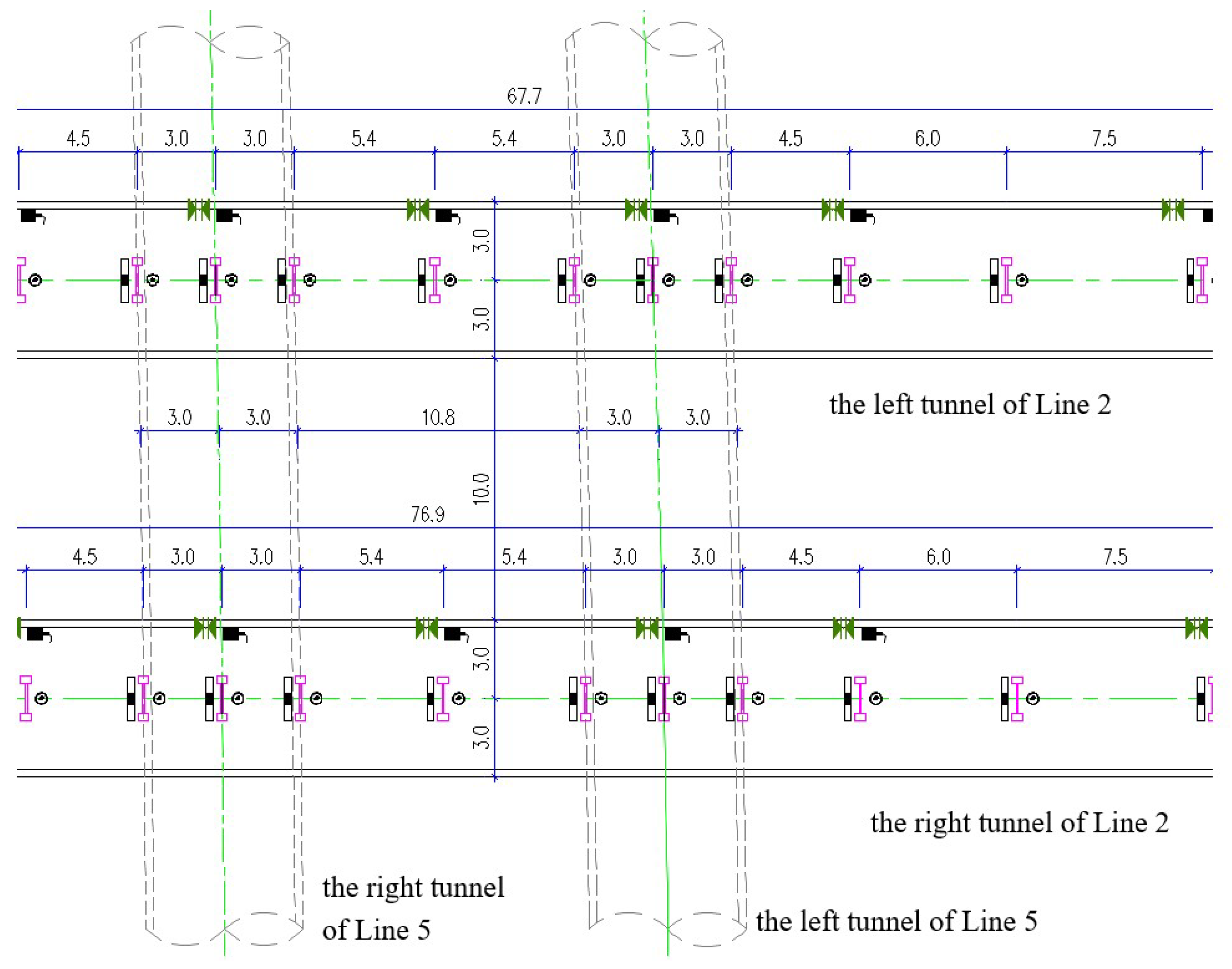
5.1. Layout of Monitoring Points

The monitoring scope for this project covers a range of 45 m to either side of the center of the new tunnel lines crossing beneath the existing tunnel, corresponding to the existing tunnel section from Z(Y)DK35 + 330 to Z(Y)DK35 + 420. The safety monitoring of the existing tunnel primarily relies on automated monitoring, supplemented by manual monitoring for verification. The automated monitoring includes items such as vertical displacement, horizontal displacement, convergence of the tunnel structure, and vertical displacement of the track bed structure, while the manual monitoring verification items mainly include vertical displacement of the tunnel structure and track bed structure. The automated monitoring employs a Leica TS-60 total station system with wireless data transmission technology. Along the existing tunnel, a monitoring section is set up every 3–9 m. The left line has a total of 14 sections, and the right line has 16 sections. Each monitoring section is equipped with two prisms on either side of the track bed and two prisms at the 3 o’clock and 9 o’clock positions of the tunnel arch. Manual monitoring points are set up on the same sections as the automated monitoring, with each section having one vertical displacement monitoring point for the tunnel structure and two vertical displacement monitoring points for the track bed structure, corresponding to the automated monitoring points. During the hazardous crossing section, the frequency of manual monitoring verification is once per day. The layout of the automated monitoring points for the existing tunnel is shown in Figure 8.
Considering the characteristics of existing urban rail transit structures, operational safety requirements, deformation during construction, and local engineering experience, the settlement value, settlement rate, and differential settlement in different sections of the tunnel structure are used as monitoring and early warning control indicators. The monitoring and early warning are divided into three levels: warning value, alarm value, and control value. The warning value is set to 60% of the control value and the alarm value is set to 80% of the control value. The deformation monitoring control standards for crossing beneath the existing tunnel are shown in Table 2. As shown in Table 2, the deformation monitoring control standards are critical for ensuring the safety and stability of the existing tunnel during the construction of the new tunnel. The warning and alarm values are established to provide early detection of potential issues, allowing for the timely intervention and adjustment of the construction parameters. For instance, a warning value set at 60% of the control value allows for preemptive measures to be taken if deformation approaches the threshold, while an alarm value at 80% of the control value indicates a more urgent need for action.

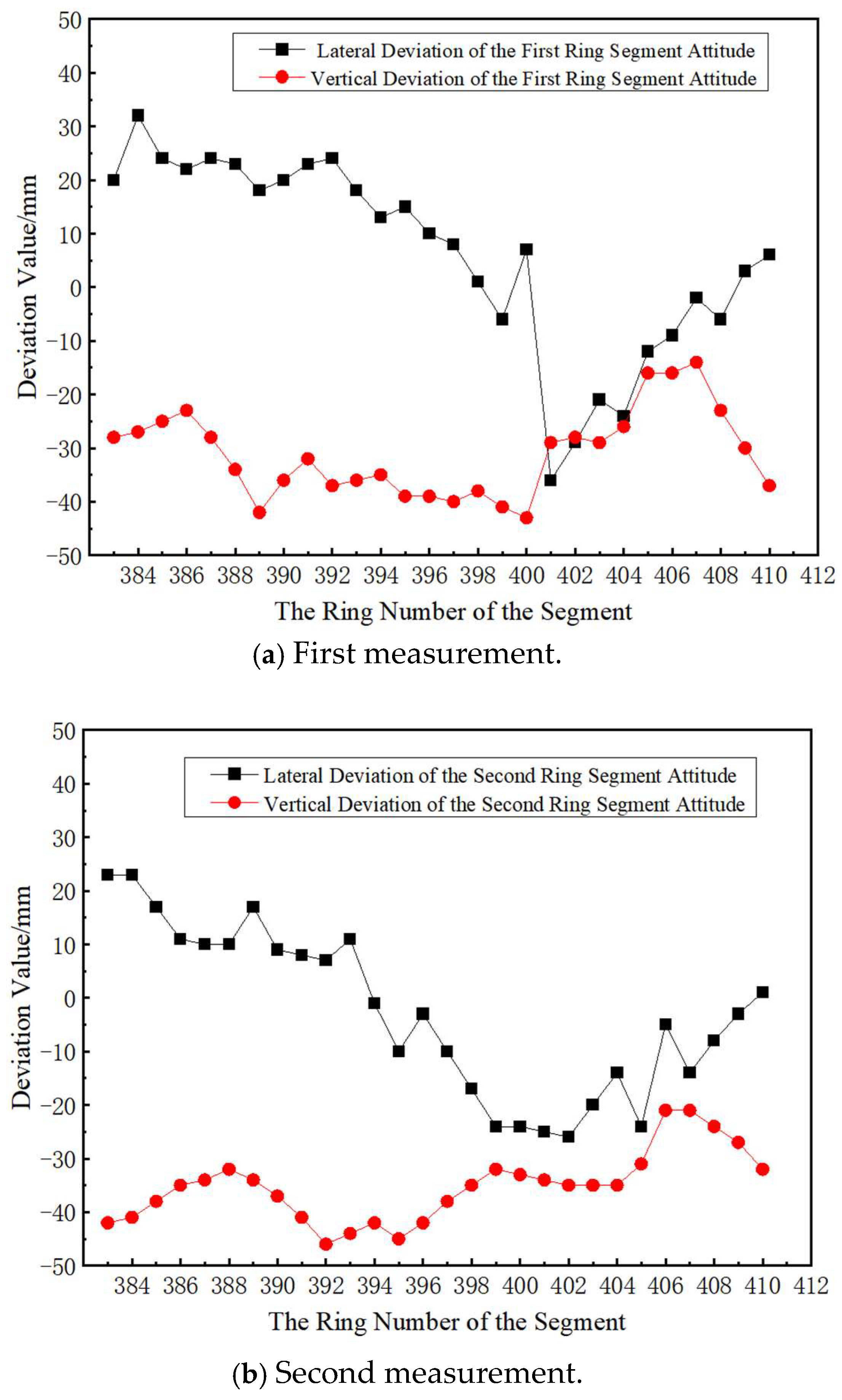
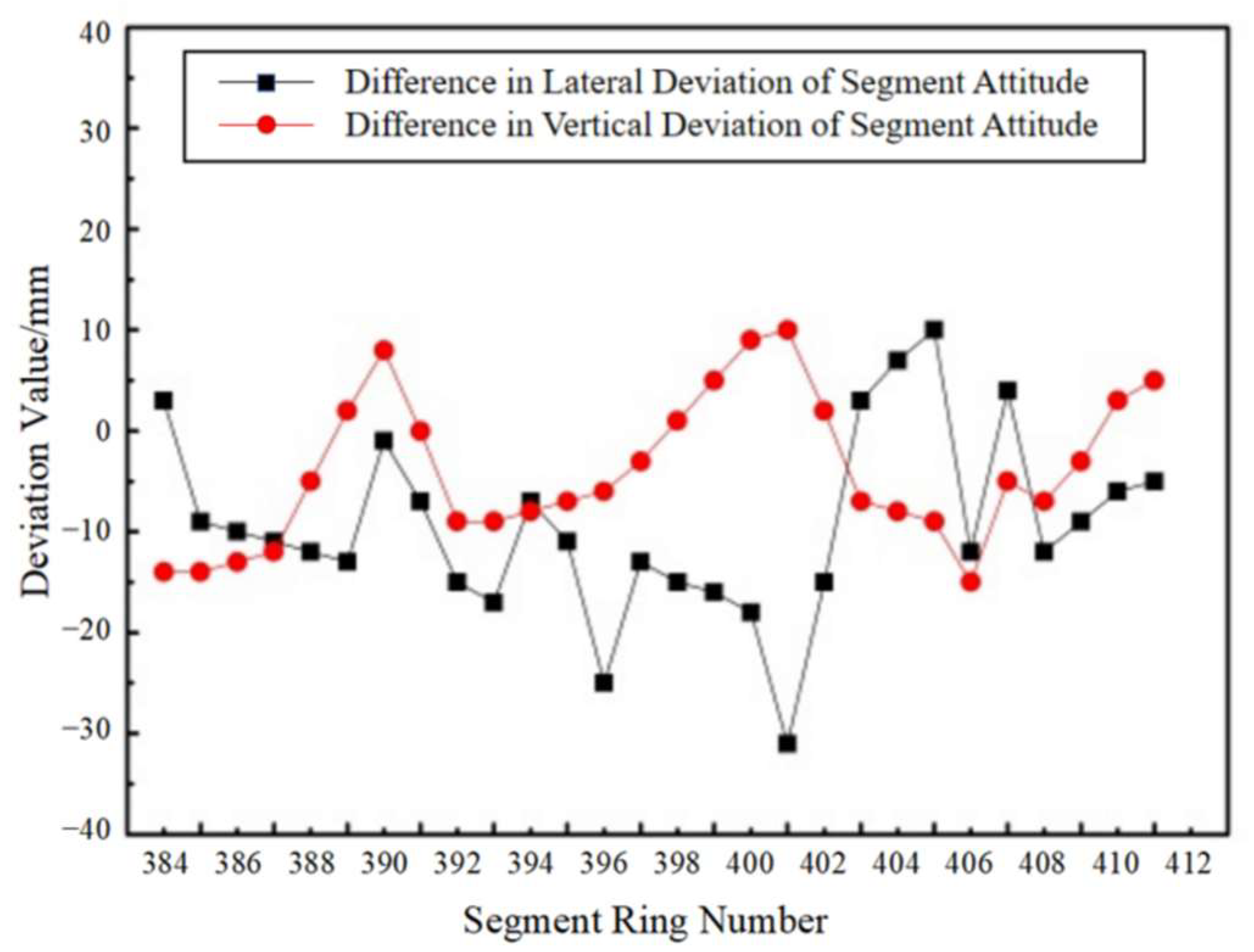
5.2. Monitoring Results and Analysis

During the shield tunneling process of the new tunnel, the strong ground disturbance caused by the cutterhead is the main reason for the deformation of the existing tunnel. When the shield machine excavates in the “soft-over-hard” stratum, the forces on the cutterhead are complex, and severe tool wear and cutterhead clogging with mud can easily occur, further intensifying the ground disturbance. This leads to a redistribution of stress in the ground beneath the existing tunnel, causing additional deformation of the existing tunnel. Especially in the crossing section, the inhomogeneity of the stratum is more pronounced, and the difficulty of adjusting the shield machine’s posture increases, making it easier for segment misalignment to occur, which in turn affects the stability of the tunnel structure. During the construction process of the new shield tunnel crossing beneath the existing tunnel, the deformation of the existing tunnel was monitored in real-time through a combination of automated and manual monitoring methods. The deformation curves of the track bed of the existing tunnel’s left and right lines after the first and second crossings are shown in Figure 9. The monitoring results indicate that the deformation of the existing tunnel caused by the construction of the new tunnel is within a controllable range, but the deformation characteristics at different stages are different.
The right line of the new shield tunnel was the first to cross beneath the existing tunnel, taking 12 days. The maximum settlement of the track bed on the left line of the existing tunnel was −1.92 mm, with the maximum settlement occurring in the central crossing area and gradually decreasing towards both sides. Half a year later, the left line of the new shield tunnel crossed beneath the existing tunnel in 10 days of construction. After the second crossing was completed, the cumulative settlement of the track bed on the left line of the existing tunnel further increased, with the maximum settlement reaching −2.55 mm, showing a clear deformation superposition effect. The settlement of the track bed corresponding to the right line in the crossing center increased from −0.58 mm to −1.24 mm. However, it should be particularly noted that, between the first and second crossings, the excavation of the Phase II transfer station foundation, located about 22 m horizontally from the right line of the existing tunnel, caused a certain amount of uplift in both lines of the existing tunnel, reducing the final settlement of the left and right lines of the existing tunnel. The right line of the existing tunnel showed a more obvious uplift than the left line, but both were still within the deformation-monitoring control values. The excavation of the foundation changed the stress field around the existing tunnel, causing a redistribution of ground stress and resulting in uplift deformation of the existing tunnel. Since the excavation scope and depth of the foundation were large, the influence range on the existing tunnel was extensive, but through reasonable construction measures and monitoring control, the final deformation was still kept within the safe range.
The uplift observed in the existing tunnel during the excavation of the Phase II transfer station foundation highlights the dynamic nature of ground stress redistribution during construction activities. While the proposed measures in this paper, such as shield machine selection, parameter optimization, and monitoring, were primarily aimed at controlling settlement during the shield tunneling process, they also demonstrated adaptability in managing the complex ground-stress changes. The real-time monitoring system allowed for the dynamic adjustment of the construction parameters, which proved to be effective in maintaining the stability of the existing tunnel despite the uplift caused by the nearby excavation. This indicates that the proposed measures have a broad applicability in managing deformation risks in complex construction environments, even when unexpected ground movements occur due to adjacent construction activities.

6. Conclusions

This study provides insights into the safety risk assessment and control measures for constructing new double-line shield tunnels crossing beneath existing tunnels in complex strata. The findings are as follows:
(1)
Engineering involving the construction of new tunnels at close proximity beneath existing tunnels poses extremely high safety risks, especially under complex geological conditions characterized by “soft-over-hard” strata, where construction uncertainties are significantly increased. Using refined risk assessment and control measures, major risk sources during the construction process were successfully identified and effectively managed. Comprehensive technical measures, including optimized shield machine selection, improved lining design, interlayer soil reinforcement, the dynamic adjustment of shield parameters, and the precise measurement of shield posture, enhanced the efficiency of shield tunneling and construction safety.
(2)
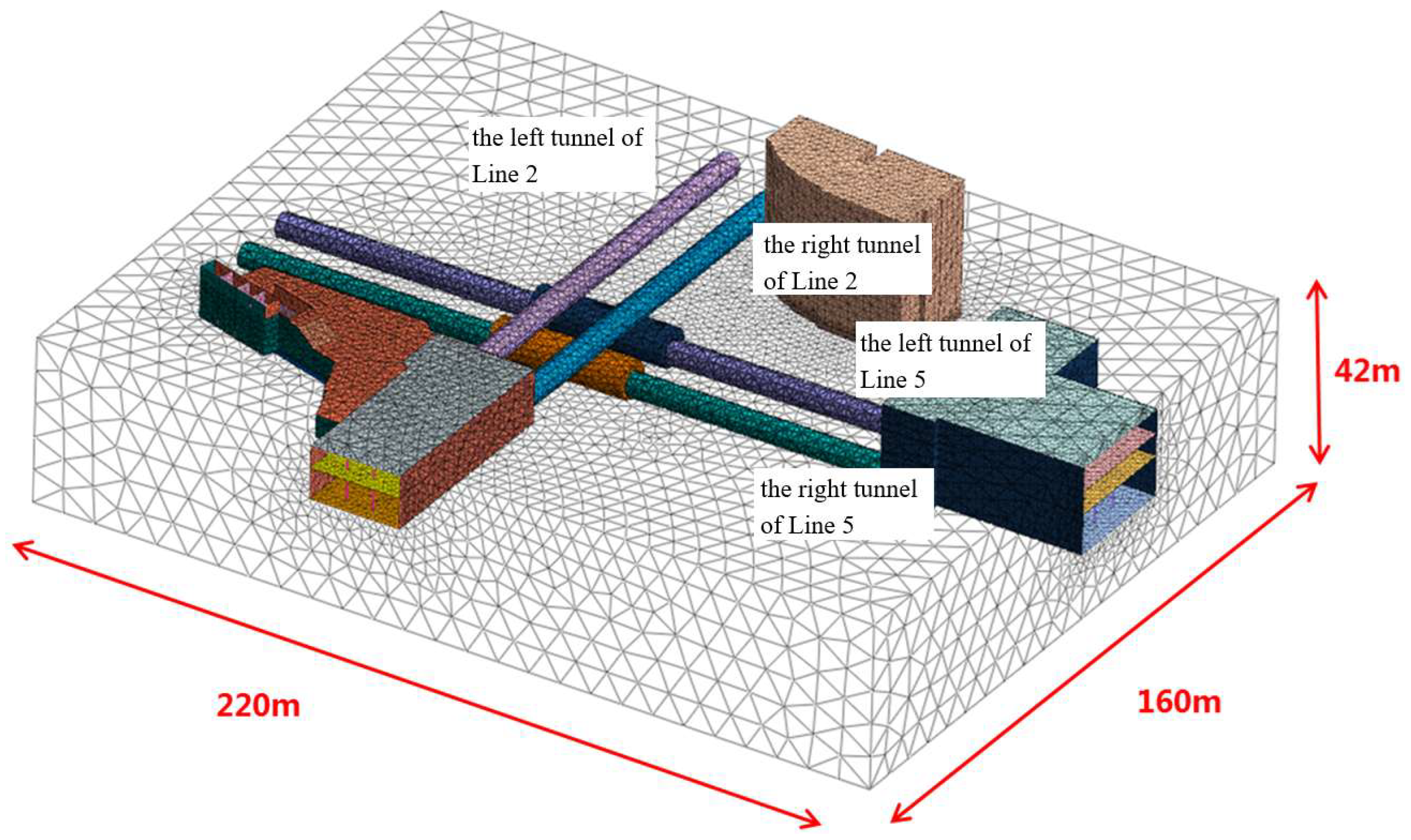
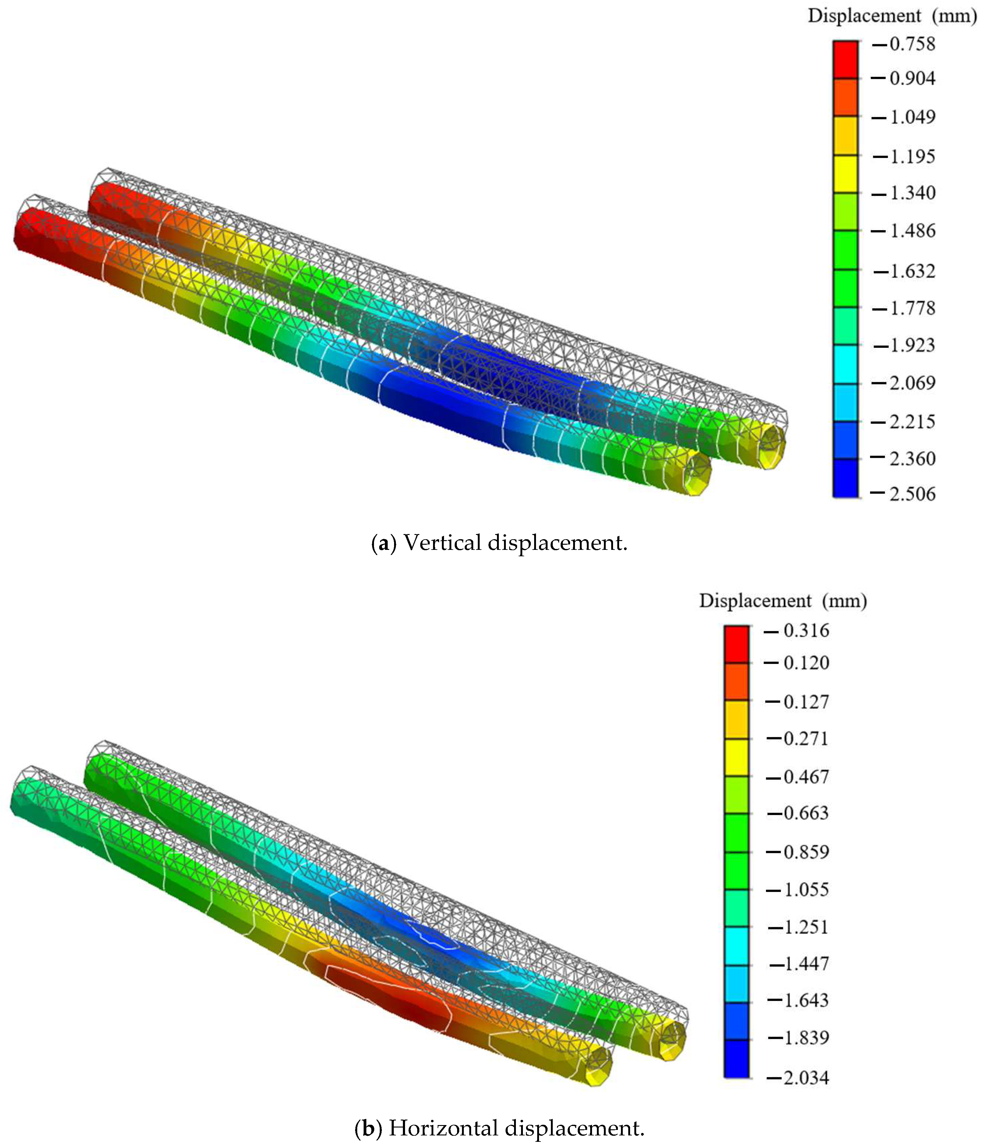
By employing three-dimensional finite element software to model and simulate the construction process of the new tunnel crossing beneath the existing tunnel, the stress and deformation characteristics of the existing tunnel structure under various working conditions were analyzed. The numerical simulation results were validated against on-site monitoring data, clarifying the reinforcement and monitoring scope for both the existing and new tunnels.
(3)
Through the analysis of monitoring and measurement data during the shield crossing process, the maximum settlement of the existing tunnel was predicted and controlled. The actual maximum settlement measured was −2.55 mm, and all cumulative deformations were within the monitoring control values, demonstrating that the selected type of shield machine and its tunneling parameters fully met the requirements for shield tunneling construction in complex strata. This study also provides a reference for the settlement and deformation control of similar projects.

7. Future Work

In this study, the field monitoring data were limited to a specific case study, and the study focuses primarily on the construction phase without an extensive long-term operational impact analysis. Future work should conduct long-term monitoring and integrate real-time data with predictive models. The development of hybrid models combining machine learning and traditional numerical methods could also offer new insights into tunneling-induced deformations.

Author Contributions

Conceptualization, B.R.; methodology, B.R., S.H., M.H., Z.C. and H.L.; software, Z.C.; validation, B.R., S.H. and H.L.; formal analysis, B.R. and H.L.; investigation, H.L.; resources, B.R., S.H., Z.C. and H.L.; data curation, M.H. and Z.C.; writing—original draft preparation, B.R.; writing—review and editing, B.R. All authors have read and agreed to the published version of the manuscript.

Funding

This paper received funding from Project (2021) of Study on Flood Disaster Prevention Model of Nanning Rail Transit.

Institutional Review Board Statement

On behalf of all authors, the corresponding author states that there are no conflicts of interest. This article does not contain any studies with human participants or animals performed by any of the authors.

Data Availability Statement

The data used to support the findings of this study are available from the corresponding author upon request.

Acknowledgments

The authors express gratitude for the financial support extended by the organizations referenced in the funding section.

Conflicts of Interest

Author Bafeng Ren and Zhi Chen were employed by the company Nanning Rail Transit Co., Ltd. The remaining authors declare that the research was conducted in the absence of any commercial or financial relationships that could be construed as a potential conflict of interest.

References

  1. Zhang, K.; Zhang, Z.; Chen, H.; Hu, Z. Experimental investigation on rheological properties and diffusion-related performance of clay shock slurry for excavation gap filling during shield tunnelling. Tunn. Undergr. Space Technol. 2024, 146, 105660. [Google Scholar] [CrossRef]
  2. Jin, D.; Yuan, D.; Li, X.; Zheng, H. Analysis of the settlement of an existing tunnel induced by shield tunneling underneath. Tunn. Undergr. Space Technol. 2018, 81, 209–220. [Google Scholar] [CrossRef]
  3. Shan, Y.; Wang, G.; Lin, W.; Zhou, S.; Rackwitz, F. Analytical solution of the evolution of railway subgrade settlement induced by shield tunnelling beneath considering soil stress release. Tunn. Undergr. Space Technol. 2025, 162, 106607. [Google Scholar] [CrossRef]
  4. Chen, Y.; Lin, H.; Liu, B. Review of Research Progresses and Application of Geothermal Disaster Prevention on Large-Buried Tunnels. Appl. Sci. 2022, 12, 10950. [Google Scholar] [CrossRef]
  5. Wu, S.; Zhang, X.; Lin, Z.; Wang, J.; Zhang, F.; Gao, H. Influence law and determination method of jack lifting load on existing station settlement. Case Stud. Constr. Mater. 2025, 22, e04180. [Google Scholar] [CrossRef]
  6. Li, J.; Fang, X.; Yang, Y. Analysis of the Impact of the New Two-Lane Shield Tunnel Underpass on the Existing Tunnels. Appl. Sci. 2025, 15, 2642. [Google Scholar] [CrossRef]
  7. Huang, W.; Liu, W.; Ou, M.-T.; Zhao, L. Numerical Analysis of Disturbance Control in a Four-Hole Parallel Tunnel Crossing Beneath Existing Tunnels. Geotech. Geol. Eng. 2025, 43, 75. [Google Scholar] [CrossRef]
  8. Lei, M.-F.; Shi, Y.-B.; Tang, Q.-L.; Sun, N.-X.; Tang, Z.-H.; Gong, C.-J. Construction control technology of a four-hole shield tunnel passing through pile foundations of an existing bridge: A case study. J. Cent. South Univ. 2023, 30, 2360–2373. [Google Scholar] [CrossRef]
  9. Pang, Y.; Lin, H.; Cao, P.; Meng, G. The Influence of Overlying High-Speed Rail Dynamic Loads on the Stability of Shield Tunnel Faces During Excavation. Appl. Sci. 2025, 15, 2567. [Google Scholar] [CrossRef]
  10. Zhang, X.; Lin, Y.; Pan, Z.; Jiang, X. Risk assessment of water inrush in deep-buried karst tunnel with rich water based on combined weighting method. Earth Sci. Inform. 2025, 18, 28. [Google Scholar] [CrossRef]
  11. Ter-Martirosyan, A.Z.; Anzhelo, G.O.; Rud, V.V. The Influence of Metro Tunnel Construction Parameters on the Settlement of Surrounding Buildings. Appl. Sci. 2024, 14, 6435. [Google Scholar] [CrossRef]
  12. Gan, X.; Yu, J.; Bezuijen, A.; Gong, X.; Wang, C. Tunneling-induced longitudinal responses of existing tunnel with discontinuities in structure stiffness. Transp. Geotech. 2023, 42, 101113. [Google Scholar] [CrossRef]
  13. Liu, B.; Li, T.; Chang, W.; Han, Y.; Fu, C.; Yu, Z. Mechanical response of horseshoe-shaped tunnel lining to undercrossing construction of a new subway station. Tunn. Undergr. Space Technol. 2022, 128, 104652. [Google Scholar] [CrossRef]
  14. Guo, P.; Gong, X.; Wang, Y.; Lin, H.; Zhao, Y. Analysis of observed performance of a deep excavation straddled by shallowly buried pressurized pipelines and underneath traversed by planned tunnels. Tunn. Undergr. Space Technol. 2023, 132, 104946. [Google Scholar] [CrossRef]
  15. Zhang, D.-M.; Xie, X.-C.; Huang, Z.-K.; Peng, M.-Z.; Zhu, H.-X. Observed response of maglev structure undercrossed by three shield tunnels in soft soil. Undergr. Space 2022, 7, 636–661. [Google Scholar] [CrossRef]
  16. Xun, X.; Zhang, J.; Yuan, Y. Multi-Information Fusion Based on BIM and Intuitionistic Fuzzy D-S Evidence Theory for Safety Risk Assessment of Undersea Tunnel Construction Projects. Buildings 2022, 12, 1802. [Google Scholar] [CrossRef]
  17. Huang, H.-W.; Gao, T.-R.; Zhang, D.-M.; Jiang, Q.-H.; Jia, J.-W. A hybrid approach for modifying tunneling-induced response in existing multi-tunnel environment. Comput. Geotech. 2025, 179, 106921. [Google Scholar] [CrossRef]
  18. Yang, W.; Zhang, D.; Wang, A. Field measurement analysis of the influence of simultaneous construction of river channel and bridge on existing double shield tunnels. Undergr. Space 2022, 7, 812–832. [Google Scholar] [CrossRef]
  19. Li, Y.; Zhang, Z.; Dong, J.; Wang, B.; Wang, C. Study on the Impact of Groundwater and Soil Parameters on Tunnel Deformation and Sensitivity Analysis. Appl. Sci. 2024, 14, 8196. [Google Scholar] [CrossRef]
  20. Han, Y.; Xu, Q.; Cui, Y. Deformation of Existing Shield Tunnel Adjacent to Deep Excavations: Simulation and Monitoring Analysis. Appl. Sci. 2024, 14, 4153. [Google Scholar] [CrossRef]
  21. Zhang, H.; Liu, G.; Liu, Q.; Chen, Z.; Wang, Z.; Niu, X. Vehicle-induced dynamic response characteristics of a new subway tunnel closely undercrossing the existing subway. Soil Dyn. Earthq. Eng. 2023, 164, 107579. [Google Scholar] [CrossRef]
  22. Huang, F.; Wang, Y.; Zhang, M.; Jiang, W.; Ji, H.; Pan, Q. Model test study of punching shear failure mode of the bearing stratum induced by tunneling beneath an existing pile. Tunn. Undergr. Space Technol. 2025, 158, 106459. [Google Scholar] [CrossRef]
  23. Chen, H.; Liu, J.; Shen, G.Q.; Feng, Z. Control of existing tunnel deformation caused by shield adjacent undercrossing construction using interpretable machine learning and multiobjective optimization. Autom. Constr. 2025, 170, 105943. [Google Scholar] [CrossRef]
  24. Liu, W.; Chen, Y.; Liu, T.; Liu, W.; Li, J.; Chen, Y. Shield tunneling efficiency and stability enhancement based on interpretable machine learning and multi-objective optimization. Undergr. Space 2025, 22, 320–336. [Google Scholar] [CrossRef]
  25. Liu, D.; Zhang, W.; Duan, K.; Zuo, J.; Li, M.; Zhang, X.; Huang, X.; Liang, X. Intelligent prediction and optimization of ground settlement induced by shield tunneling construction. Tunn. Undergr. Space Technol. 2025, 160, 106486. [Google Scholar] [CrossRef]
  26. Chen, H.; Liu, J.; Shen, Q.G.; Li, T.; Liu, Y. Data-driven joint multiobjective prediction and optimization for tunnel-induced adjacent bridge pier displacement: A case study in China. Eng. Appl. Artif. Intell. 2025, 142, 109616. [Google Scholar] [CrossRef]
  27. Guo, T.; Li, S.; Lu, B.; Wang, Z.; Cao, W.; Liu, S. Research on gradual optimization of slurry mixture ratio for shield tunnel backfill grouting based on fuzzy mathematics. Constr. Build. Mater. 2024, 456, 139319. [Google Scholar] [CrossRef]
  28. Zhou, X.; Zhao, C.; Bian, X. Prediction of maximum ground surface settlement induced by shield tunneling using XGBoost algorithm with golden-sine seagull optimization. Comput. Geotech. 2023, 154, 105156. [Google Scholar] [CrossRef]
  29. Ma, S.; Zhou, Z.; Duan, Z.; Huang, Z.; He, B.; An, P.; Li, J. Study on the Influence Characteristics of Excavation Face Instability of New Tunnels Orthogonally Crossing Existing Tunnels. Appl. Sci. 2024, 14, 10521. [Google Scholar] [CrossRef]
  30. Liu, X.; Jiang, A.; Fang, Q.; Wan, Y.; Li, J.; Guo, X. Spatiotemporal Deformation of Existing Pipeline Due to New Shield Tunnelling Parallel Beneath Considering Construction Process. Appl. Sci. 2022, 12, 500. [Google Scholar] [CrossRef]
  31. Cetindemir, O. Nonlinear Constitutive Soil Models for the Soil-Structure Interaction Modeling Issues with Emphasis on Shallow Tunnels: A Review. Arab. J. Sci. Eng. 2023, 48, 12657–12691. [Google Scholar] [CrossRef]
  32. Mao, Z.; Ding, T.; Hu, F.; Ye, S.; Ding, L.; Zhang, X.; Li, P.; Li, N. The Impact of Different Excavation Support Structures on the Deformation and Stability of Adjacent Station and Tunnels. Buildings 2025, 15, 493. [Google Scholar] [CrossRef]
  33. Zheng, F.; Li, W.; Song, Z.; Wang, J.; Zhang, Y.; Liu, N.; Xiao, K.; Wang, Y. Construction Stability Analysis and Field Monitoring of Shallowly Buried Large-Section Tunnels in Loess Strata. Water 2024, 16, 2192. [Google Scholar] [CrossRef]
  34. Liu, H.; Ma, W.; Kang, M.; Fu, Y.; Yan, T.; Liu, H.; Zhao, B. Study on the Distribution Law of External Water Pressure with Limited Discharge during Shield Construction of Soft Rock Tunnel in Western Henan Province. Appl. Sci. 2024, 14, 5698. [Google Scholar] [CrossRef]
  35. Robert, D.J. A Modified Mohr-Coulomb Model to Simulate the Behavior of Pipelines in Unsaturated Soils. Comput. Geotech. 2017, 91, 146–160. [Google Scholar] [CrossRef]
  36. Vicente da Silva, M. Nonlinear Mohr–Coulomb yield criterion: Integration in ADMM-based finite element limit analysis formulation and application to slope stability assessment. Comput. Geotech. 2025, 177, 106897. [Google Scholar] [CrossRef]
Figure 1. Location relationship of the crossing section.
Buildings 15 02103 g001
Figure 2. Improved lining segments and optimized grouting.
Buildings 15 02103 g002
Figure 3. Three-dimensional numerical model.
Buildings 15 02103 g003
Figure 4. Deformation of the existing tunnel after the right line passed through.
Buildings 15 02103 g004
Figure 5. Deformation of the existing tunnel after the left line passed through.
Buildings 15 02103 g005
Figure 6. Segment posture measurement deviation.
Buildings 15 02103 g006
Figure 7. Segment posture measurement deviation in worse cases.
Buildings 15 02103 g007
Figure 8. Layout of automated monitoring points for existing tunnel.
Buildings 15 02103 g008
Figure 9. Deformation curves of the track bed of the left and right lines of the existing tunnel after the first and second crossings.
Buildings 15 02103 g009
Table 1. Geotechnical calculation parameters.
StratumThickness (m)Density (g/cm3)Cohesion (kPa)Internal Friction Angle (°)
Plain Fill Soil21.941611
Silty Clay32.002513.5
Silt12.05617
Fine Sand72.10220
Gravel82.06034
Mudstone172.138517.5
Table 2. Deformation monitoring control standards for crossings beneath existing tunnels.
Monitoring ItemCumulative Control ValueDeformation Rate Control Value
Vertical Displacement of Tunnel Structure+3mm, −5mm±2 mm per single measurement, settlement rate reaching 1 mm/day
Horizontal Displacement of Tunnel Structure±4mm
Convergence of Tunnel Structure±5mm
Vertical Displacement of Track Bed+3mm, −5mm
Disclaimer/Publisher’s Note: The statements, opinions and data contained in all publications are solely those of the individual author(s) and contributor(s) and not of MDPI and/or the editor(s). MDPI and/or the editor(s) disclaim responsibility for any injury to people or property resulting from any ideas, methods, instructions or products referred to in the content.

