1. Introduction
With the acceleration of urbanization, foundation pit support technology has become increasingly important in deep foundation pit engineering. The traditional foundation pit support system usually adopts shotcrete surface layers, and in a large number of practical projects, the cases of foundation pit collapse and damage are relatively few. However, as China‘s “14th Five-Year Plan” proposes to strengthen ecological environment protection and promote the innovation and application of green and low-carbon technologies, the distinct soil properties of the loess region present specific challenges in the design and construction of foundation pit support in this area. Therefore, in view of the special needs of the loess area, a new type of support system is needed, which not only meets the requirements of foundation pit support, but also has low cost and is green, with low-carbon environmental protection.
Nowadays, the research on foundation pit supporting systems is relatively mature. Researchers have explored theoretical methods, numerical analysis, and experimental research [
1,
2,
3,
4]. Among them, Zhi, B. [
5] conducted a model test on the shotcrete surface support for a traditional soil nailing wall. Additionally, the failure modes of the soil-nailed wall and the unreinforced slope were compared during excavation and loading. Yazdandoust, M. [
6] conducted a shaking table test on a scaled model of a spiral soil nailing wall. The influence of soil nail configuration and inclination on the retaining wall’s failure mode and seismic response was examined. Failure mechanism of Bayat, M. [
7] on soil-nailed wall structure with shotcrete cover under earthquake action. Bayesteh, H. [
8] evaluated the application of shotcrete surface in the soil nailing retrofit of existing masonry retaining walls. Mohamed, M. H. [
9] studied the variation of soil nailing slope under different soil and building foundation parameters. Jalota, S. [
10] constructed a scale model of a soil nailing slope using various flexible facings and compared the variations in the slope with a flexible facing material to that of a slope without a surface layer. Guo, Y. [
11] examined how vibrations caused by pile driving affect soil strength and the strength of the soil–nail interface. The research also focused on the variations in the axial force and displacement of the soil nails. Shoar, S. M. S. [
12] assessed the impact of extra load on the vertical excavation behavior of soil nails using centrifuge testing. In addressing slope stability issues, Ramteke, P. C. [
13] created a three-dimensional finite element model to simulate the structural response under additional load and conducted experimental studies to evaluate the impact of extra load on the soil nailing slope and wall.
Ehrlich, M. [
14] used numerical methods to evaluate the effects of excavation procedures and soil nailing stiffness, inclination, and position, and the impact of near-base excavation on nail–soil system behavior under service loads. Momeni, M. [
15] used Plaxis and GeoSlope software to evaluate the optimal distance and placement length of soil nails under various conditions, and used the results of other studies to improve the reliability of the foundation pit. Won, M. S. [
16] used PLAXIS 3D to analyze the finite element model parametrically, examining grouted soil nail pull-out behavior. Sabermahani, M. [
17] studied the influence of soil nail layout through physical modeling and introduced the limit equilibrium analysis results of different nail layouts. Gui, M. [
18] conducted simulations of the full-scale soil nailing support excavation process for a foundation pit, aiming to investigate the impact of different combinations of strip foundations placed on top of the excavated pit. By applying plastic limit analysis and the vertical strip segmentation method.
Based on the research above, it has been observed that both domestic and international scholars primarily focus on studying the length, placement angle of soil nails, and their impact on the supporting effectiveness of foundation pits under external environmental influences, often using numerical simulations or model box tests. Moreover, while several researchers have conducted extensive studies on the types of shotcrete surface layers, there has been limited research on the materials used for soil nail walls. Therefore, this paper uses the loess and cement in the Lanzhou area to prepare the soil nail and surface layer of loess-based composite slurry and carries out the scale model box test. The changes in surface layer displacement and axial force of the soil nails during excavation and loading are analyzed. The step-by-step excavation process of a foundation pit reinforced by loess-based composite slurry soil nailing wall is simulated by ABAQUS finite element software. In order to find a foundation pit support system that not only meets the support effect but also meets the requirements of green development and cost reduction.
2. Materials and Methods
In this paper, a new type of green low-carbon foundation pit supporting form composed of soil nail and loess-based cement slurry surface layer is proposed. The soil nail is replaced by ordinary steel bars. The surface layer of support is made from a type of solid waste cementitious material called loess-based cement slurry, which consists of loess, cement, and various additives.
In this study, the model test adopts a geometric similarity ratio of 1:10, and the material properties used in the test closely align with those found in the actual engineering project. The size of the model box is 1.5 m × 1.0 m × 0.5 m. A total of 3 soil nailing walls are set up along the depth direction. This experiment replicates the load-bearing and deformation responses of the loess-based cement slurry surface layer and the soil nails when subjected to an applied upper load. The foundation pit excavation is carried out according to real excavation conditions, progressing in three stages, each with a depth of 20 cm. The flow chart of the model test is shown in
Figure 1.
2.1. Model Design and Production
The model box is made of a steel plate, a square steel beam, a square steel column, and organic glass by welding. The outer frame structure of the model box is welded by a square steel beam of 50 mm × 50 mm × 5 mm. The internal size of the model box is: 1.5 m (length) × 1.0 m (height) × 0.5 m (width). In the four facades of the model, 12 mm thick organic glass is set up, and the steel plate is welded and fixed on the square steel beam to observe the deformation of the soil. A steel plate is placed at the bottom of the model box for waterproofing. Industrial vaseline coats the box’s interior surfaces to minimize friction and soil–wall boundary effects.
2.2. Testing Material
2.2.1. Soil
The materials of foundation soil and slope filling are taken from the loess slope of Pengjiaping Campus in Qilihe District of Lanzhou, and the soil is uniform. The test soil needs to pass through the process of screening soil, mixing soil, soaking soil, soil blending, etc. In the course of the test, the weight of the layered filling is determined based on the compaction level. The soil is then layered and evenly packed into the model box, ensuring a dense fill. A series of geotechnical lab tests were conducted on the loess sample to determine its key physical and mechanical characteristics.
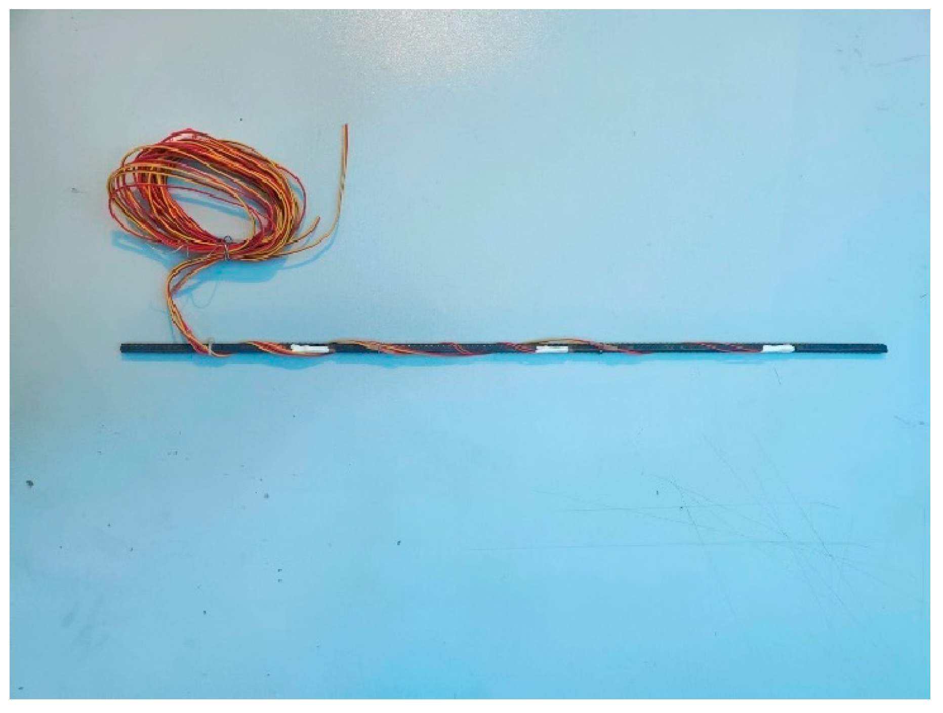
2.2.2. Soil Nailing
Based on the model test plan, a 2.2 mm steel bar was chosen, and a strain gauge was attached to it to measure the axial force. The steel bar was encased by grouting with loess-based cement slurry, as shown in
Figure 2.
2.2.3. Loess-Based Cement Slurry Surface Layer
The surface layer of loess-based cement slurry consists of 70% loess, 20% cement, and 10% additives. It is directly configured before the test, and then evenly applied to the exposed surface layer to be supported.
Figure 3 displays the surface layer of the loess-based cement slurry.
2.3. Soil Nailing Wall and Surface Layer Arrangement
The soil nails are positioned in three layers along the depth. The distances from the left glass panel to the soil nails in the first, second, and third layers are 62.5 mm, 187.5 mm, 312.5 mm, and 437.5 mm, respectively. The distance from the second layer of soil nailing to the left glass panel from left to right is 125 mm, 250 mm, and 375 mm, respectively. Soil nails are spaced 140 mm apart, with a 3 cm loess–cement slurry surface layer.
2.4. Loading System and Method
After completing the soil nailing wall, a vertical load is placed on its top surface to assess bearing capacity and deformation behavior. The test loading adopts graded loading. The graded loading can ensure the uniformity and continuity of the loading, and it is easier to observe the test phenomena during the test. Before the test, the estimated failure load was estimated, and the loading grade of each stage was finally determined to be 5 kPa. When the settlement is less than 0.1 mm per hour within two consecutive hours, it is considered to be stable and can be loaded at the next stage. Loading 7 times.
3. Results
3.1. Horizontal Displacement Analysis of Loess-Based Cement Slurry Surface Layer
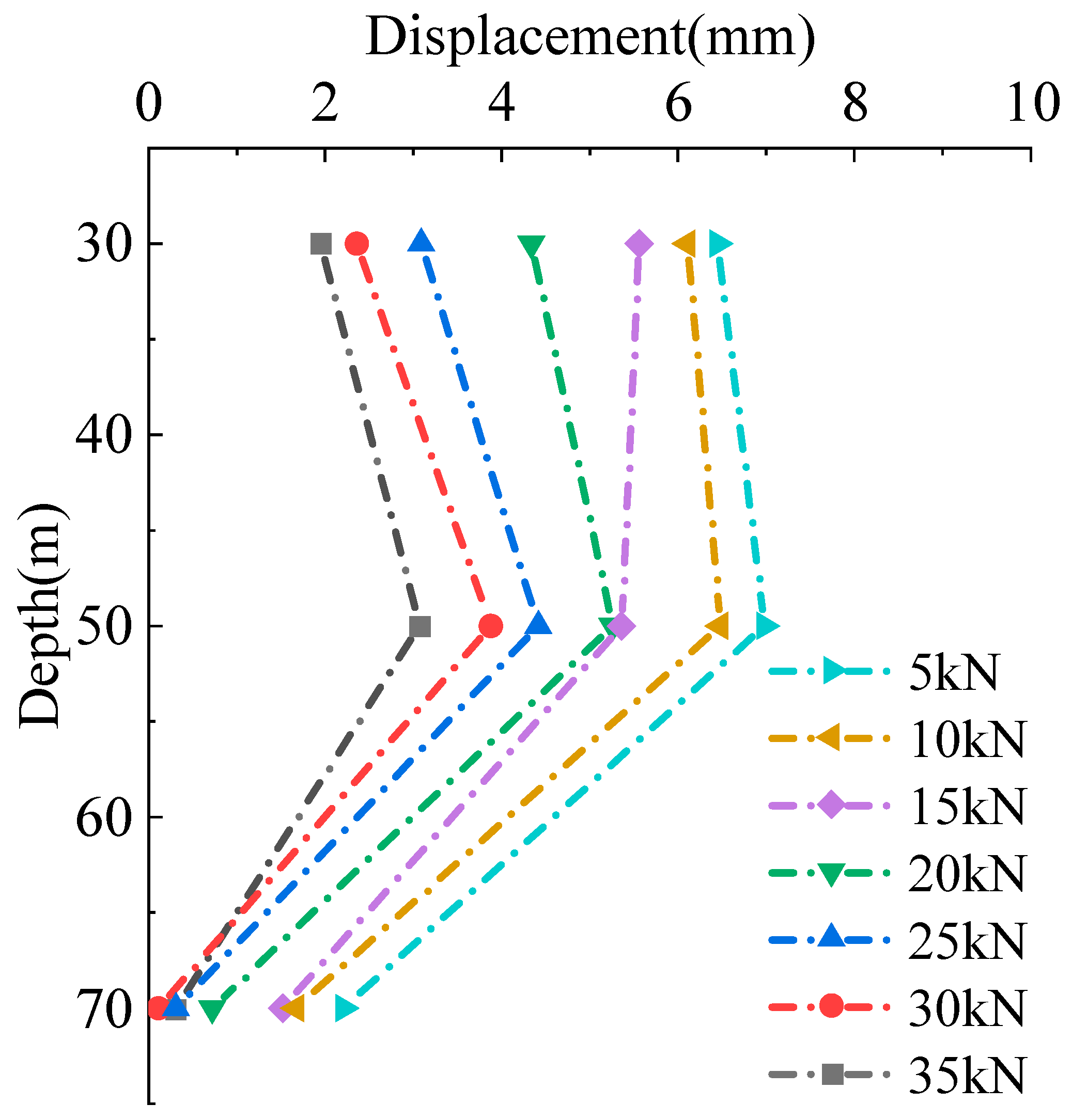
Once the soil nailing wall support is in place, vertical loading is applied to the slope top classification to further examine the horizontal displacement changes of the loess-based cement slurry surface layer, and the support of the surface layer is assessed. Throughout the loading process, the displacement of the surface layer was tracked, with
Figure 4 depicting the displacement at different depths under various loading conditions.
As depicted in
Figure 4, the displacement of the loess-based cement slurry surface layer initially increases and then decreases as the depth of the foundation pit increases. The maximum displacement is observed at the mid-depth, following a pattern of larger displacements at both ends and smaller displacements in the center. The shallow soil, being relatively loose, exhibits a greater ability to deform. As a result, the displacement becomes significant. With increasing depth, the soil’s strength progressively enhances, and the constraint from the surface layer and soil nail begins to emerge. The deep soil experiences minimal deformation, with the displacement steadily decreasing. As the vertical load grows, the displacement of the surface layer progressively increases. This is because under the action of vertical load, the surface layer initially exhibits elastic deformation. When the load increases, the soil gradually enters the plastic stage, and the soil produces irreversible deformation. As the load continues to rise, the soil undergoes increasing plastic deformation, resulting in a gradual accumulation, and the displacement of the surface layer also grows.
3.2. Analysis of Axial Force of Soil Nailing
3.2.1. Excavation Stage
It is divided into three excavations. Strain data from the soil nails are collected throughout the excavation process, and the variation in axial force of the soil nails at different stages of excavation is plotted.
Figure 5 illustrates the variation in axial force for the first row of soil nails during the excavation phase.
As shown in
Figure 5, the axial force of the first row of soil nails follows a pattern, being largest in the middle and smaller at both ends. During the three excavation processes, the maximum axial force of soil nails appears in the middle of the foundation pit. The displacement of the soil around the middle of the foundation pit is large, and the soil nail is a passive force member. Therefore, the axial force of the soil nail at this location is relatively high. As the number of excavations increases, the axial force of the soil nails also rises. As the excavation depth increases, the load from the upper soil is gradually reduced, while the weight of the lower soil continues to exert force on the excavation surface, gradually increasing the overall soil weight. Excavation causes uneven deformation of the soil near the surface, resulting in a decrease in soil pressure at the upper section and an increase in pressure at the lower section. Soil nails provide restrictions on these deformations through tension, so they need to bear more axial force.
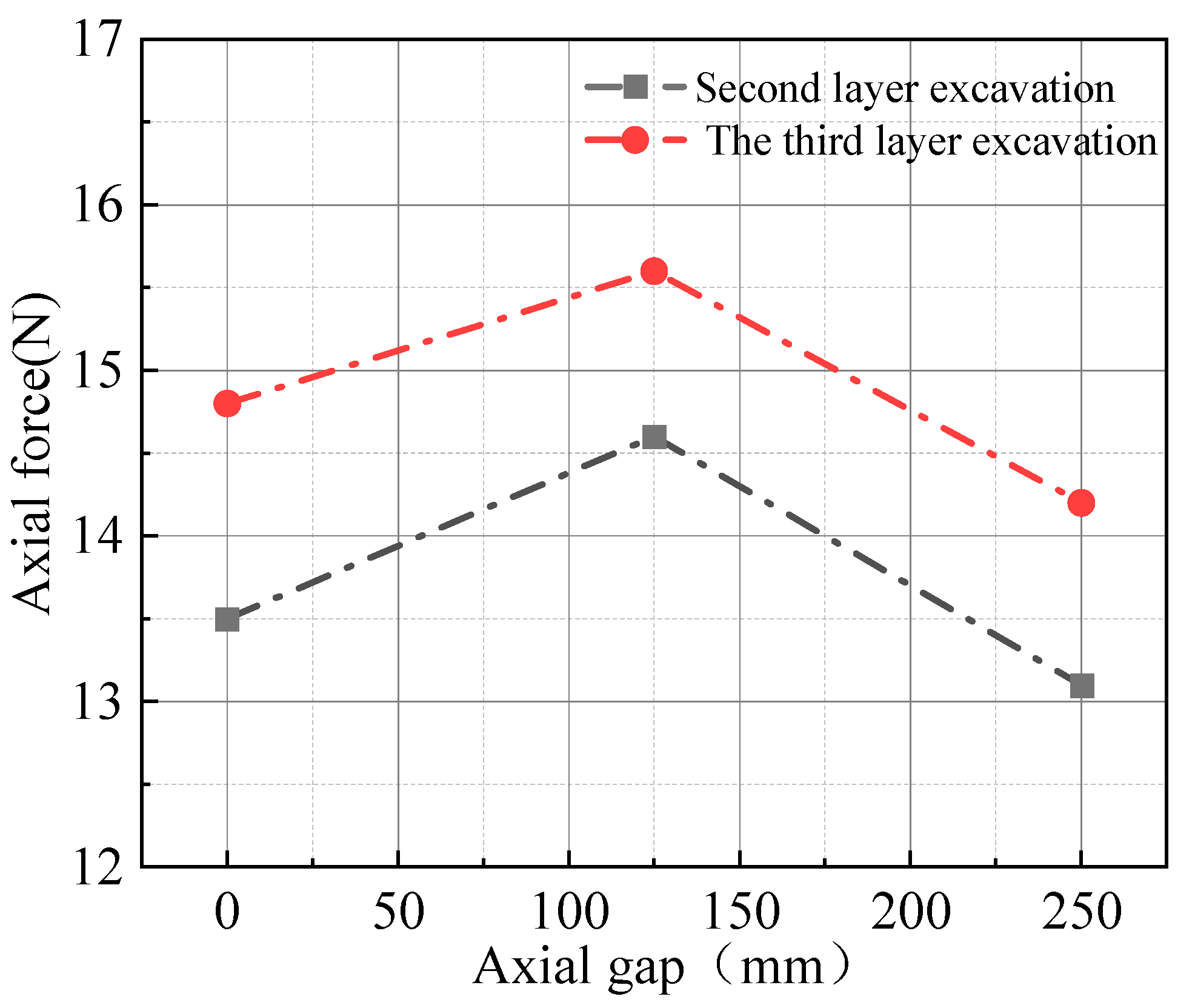
Figure 6 illustrates the change in axial force of the second row of soil nails during the excavation process. The axial force in this row exhibits a similar trend, with lower forces at the ends and a peak force in the center, occurring at the middle soil nail. After excavating the third layer, the axial force in the second row surpasses that of the first row. As excavation continues to greater depths, the disturbance in the surrounding soil expands. The increasing weight of the outer soil and the growing depth of the foundation pit lead to inward soil movement, causing the soil nails to experience higher axial forces.
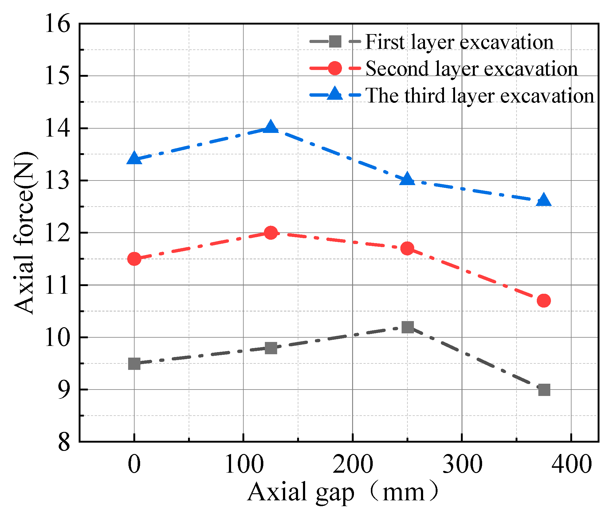
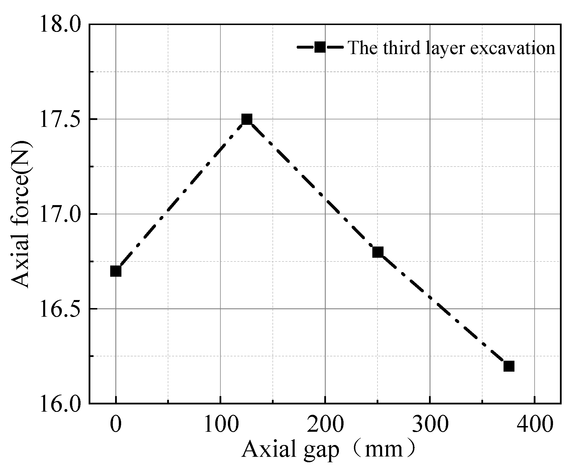
Figure 7 depicts the change in axial force of the third row of soil nails during the excavation of the foundation pit. As the excavation depth increases, the axial force of the soil nails gradually increases. This is influenced by factors such as surrounding soil deformation, the support system’s stiffness, and the excavation depth. As the bottom soil decreases, the stability of the foundation pit wall is increasingly affected. To support the additional soil weight and counteract soil subsidence and lateral deformation, the axial force in the soil nails continues to rise. With the increase of axial spacing, the axial force of soil nails increases first and then decreases. Among the four soil nails in the third row, the axial force of the middle two soil nails is slightly larger than that of the two soil nails on the edge of the model box. This is because with the continuous excavation, due to the edge effect of the model box, the soil settlement in the center of the foundation pit may be larger than that on the edge, and the soil nails in the middle part bear greater pressure, resulting in the axial force of soil nails increasing first and then decreasing with the increase of axial spacing.
3.2.2. Loading Stage
To more comprehensively evaluate the bearing capacity of the soil nail, a vertical load is applied at the top of the foundation pit. The axial force variation of the soil nail throughout the loading process is then plotted by recording the strain data during the loading.
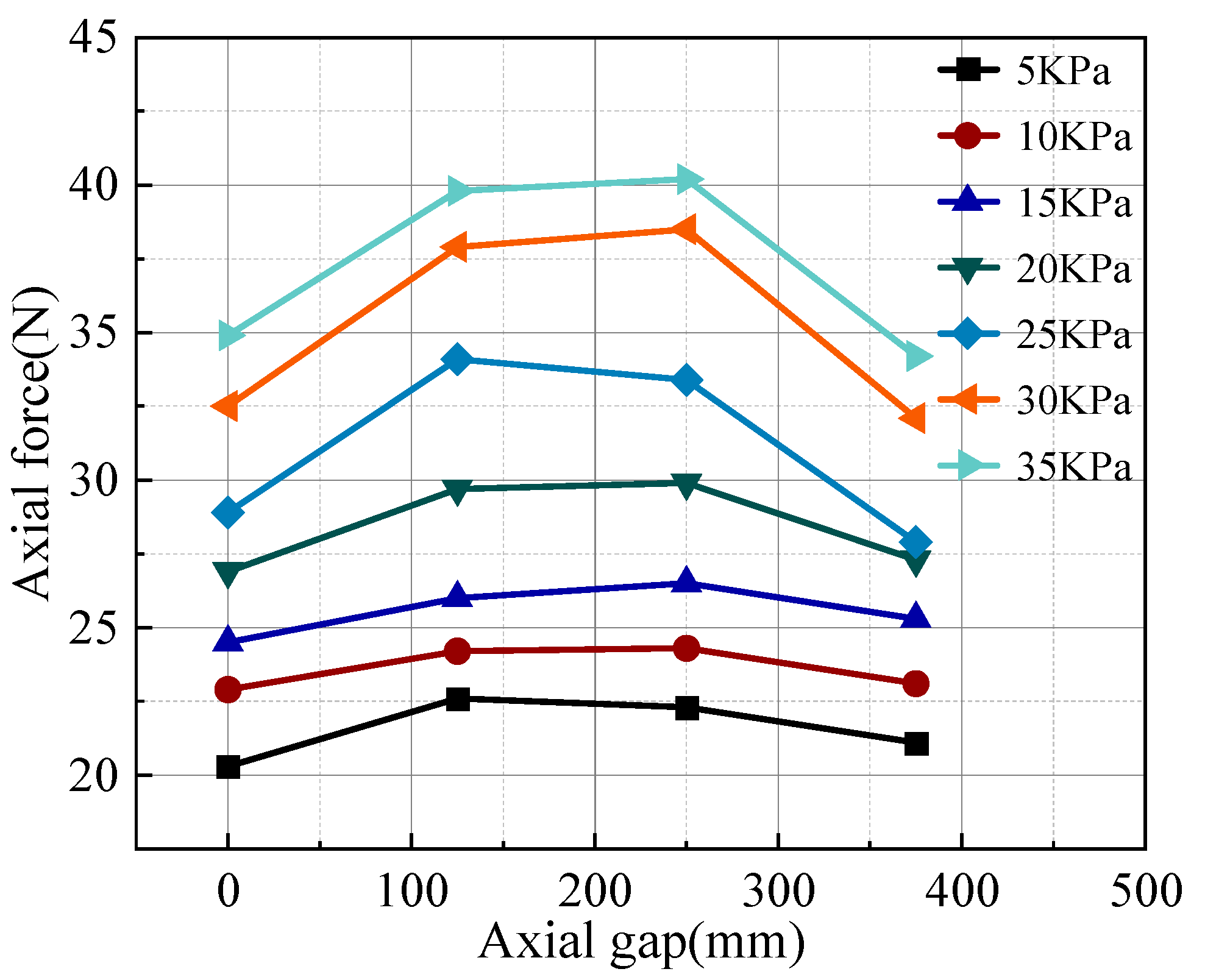
Figure 8 illustrates the change in axial force for the first row of soil nails during the loading phase. As seen in the figure, the axial force in the soil nails gradually increases with the applied load. In the initial loading phase, the axial force changes slowly. The axial force of the soil nails at both ends of the model box is similar to that of the central soil nails. However, when the applied load reaches 15 kPa, the axial force in the two central soil nails rises significantly compared to those near the ends of the model box. This occurs because the loading plate is positioned at the center of the model box.
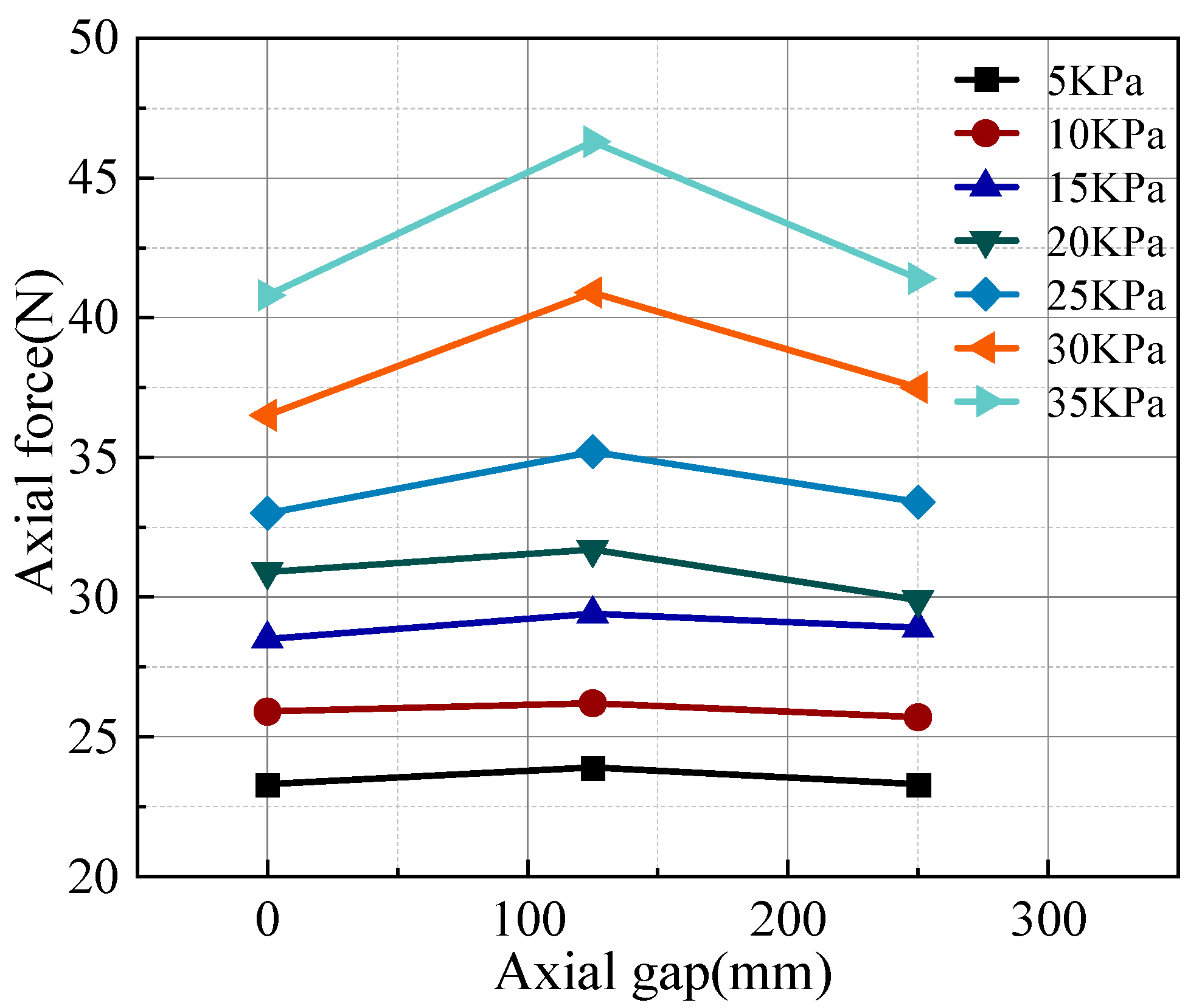
Figure 9 presents the axial force curve for the second row of soil nails during the loading stage. As depicted in the figure, the axial force in the soil nails gradually increases with the applied load. The axial force in the second row of soil nails is slightly less than that in the first row. During the early stage of loading, the axial force in the soil nails remains small. At this stage, the soil nails mainly bear the initial stress and part of the load of the soil. At a loading pressure of 25 kPa, there is a noticeable increase in the axial force of the soil nails, and the interaction between the soil and the nails becomes more pronounced.
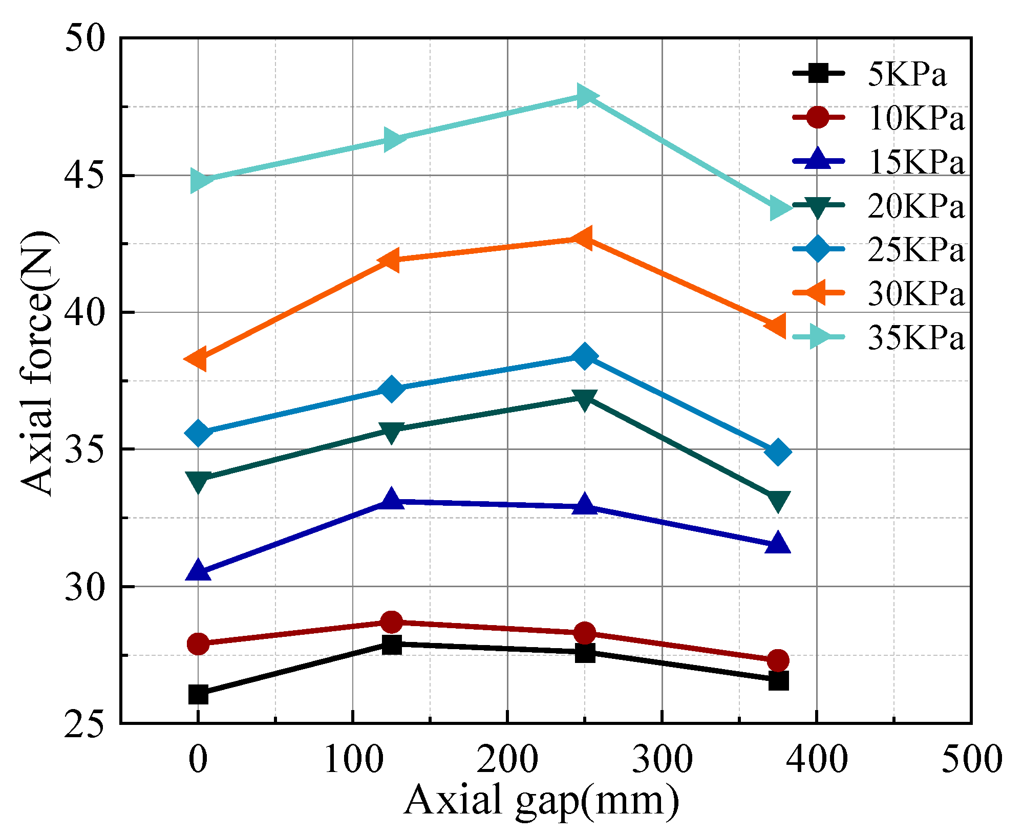
Figure 10 shows the curve representing the change in axial force for the third row of soil nails during the loading stage. Compared to the axial forces in the first and second rows, the axial force in the third row is lower. As the loading load increases, the variation in the axial force of the third-row soil nails is less pronounced than that in the first and second rows. In the initial loading, the bottom soil nails mainly bear the initial stress of the bottom soil, and the initial load is mainly concentrated on the last soil nails. As the load gradually increases, the axial force in the third row of soil nails also grows, but at a slower pace. When the loading reaches 25 kPa, the third row of soil nails begins to support a greater share of the load, leading to a significant increase in their axial force.
4. Numerical Analysis Model
Taking a foundation pit in Gansu Province as the research object, a finite element model is established. Given that the primary ground load near the foundation pit’s influence zone consists of constant and vehicle loads from the municipal road running parallel to the pit’s side, it is assumed that the main potential sliding area of the foundation pit is located near the edge of the municipal road.
4.1. Geometric Size
The geometric model is shown in
Figure 11. The depth of the foundation pit is 9.6 m, which is divided into 5 steps of excavation. The first step of excavation is 1.8 m, the second step of excavation is 2 m, the third step of excavation is 2 m, the fourth step of excavation is 2 m, and the fifth step of excavation is 1.6 m. The slope ratio of the foundation pit slope after excavation is 1:0.27. Relevant papers show that when the distance between the foundation pit slope and the horizontal boundary meets 3~4 times the excavation depth, the impact of the boundary conditions is minimal, and when the distance from the bottom boundary is 4 to 5 times the excavation depth, the effect on the bottom boundary becomes negligible. To effectively eliminate the influence of boundary conditions in foundation pit excavation, the model in this study has a horizontal length of 80 m, a depth of 40 m, and a width of 10 m, which is similar to a plane strain problem.
4.2. Material Properties
In ABAQUS, the hardening law of Mohr–Coulomb model is realized by controlling the size of cohesion c. It is necessary to specify the relationship between cohesion c and equivalent plastic strain, which can be input into ABAQUS through tables. For the cohesion between interpolation points, ABAQUS is calculated by linear interpolation. In this section, the hardening law of the soil is not considered, and there is no subsequent yield phenomenon; that is, the soil enters the ideal elastic–plastic state after yielding, and the hardening parameter is always 0.
Table 1 presents the parameters of the soil material.
For the loess-based composite slurry soil nail, from the perspective of simplified modeling, the metal ideal elastic–plastic model is adopted. When the tensile force in the loess-based composite slurry soil nail surpasses the sliding yield strength, the decrease in pull-out strength is not considered. To streamline the analysis, while taking into account the tensile and bending strengths of the loess-based composite slurry soil nail, the nail is modeled using the B31 double-node beam element. The embedment region technique is applied to facilitate interaction between the soil and the soil nail. The thickness of the surface layer of the loess-based composite slurry is 100 mm. Because the surface layer generally has reinforcement, and the relative soil can be regarded as an elastomer, the solid element simulation is also used. The common node method is applied between the surface layer of the loess-based composite slurry and the soil. To determine the relative displacement, the interpolation function is used between the surface layer of the loess-based composite slurry and the soil nail.
The bond strength response refers to the pull-out bond strength value between the soil nail and the loess-based composite slurry soil. It is assumed that the ideal elastic-plastic yield criterion of the metal is used for the soil nail. It is assumed that the pull-out section in the sample reaches the pull-out strength at the same time, and it is equivalent to the tensile yield strength of the normal section of the soil nail.
The data from the pull-out test were utilized to analyze the interaction between the loess-based composite slurry soil nail and the surrounding soil. The yield strength of the loess-based composite slurry soil nail was selected to use the loess-based composite slurry–soil bond strength under the mix ratio of 14d age, 35% water content, and 20% cement incorporation ratio as the nail–soil bond strength, as shown in
Table 2.
The compressive strength of loess-based composite slurry increases with the cement mixing ratio at a constant water content, decreases as water content rises at the same age, and improves with age at a fixed cement mixing ratio. In order to satisfy the bond strength standards for loess-based composite slurry as specified, and considering the excavation interval and the economic advantages of the upper and lower layers of the soil nailing wall during construction, the compressive strength of loess-based composite slurry with cement mixing ratios of 12%, 18%, 24%, and 30% at 14 days and 35% water content is utilized as the reference value for determining the elastic modulus of the soil nailing. The loess-based composite slurry soil nailing material is considered a linear elastic material.
Table 3 presents the calculated values for the elastic modulus of loess-based composite slurry soil nails.
Because the soil nailing wall supporting surface material is generally equipped with steel wire mesh, and the supporting surface layer can be regarded as an elastomer relative to the soil. The elastic modulus of the supporting surface is shown in
Table 4.
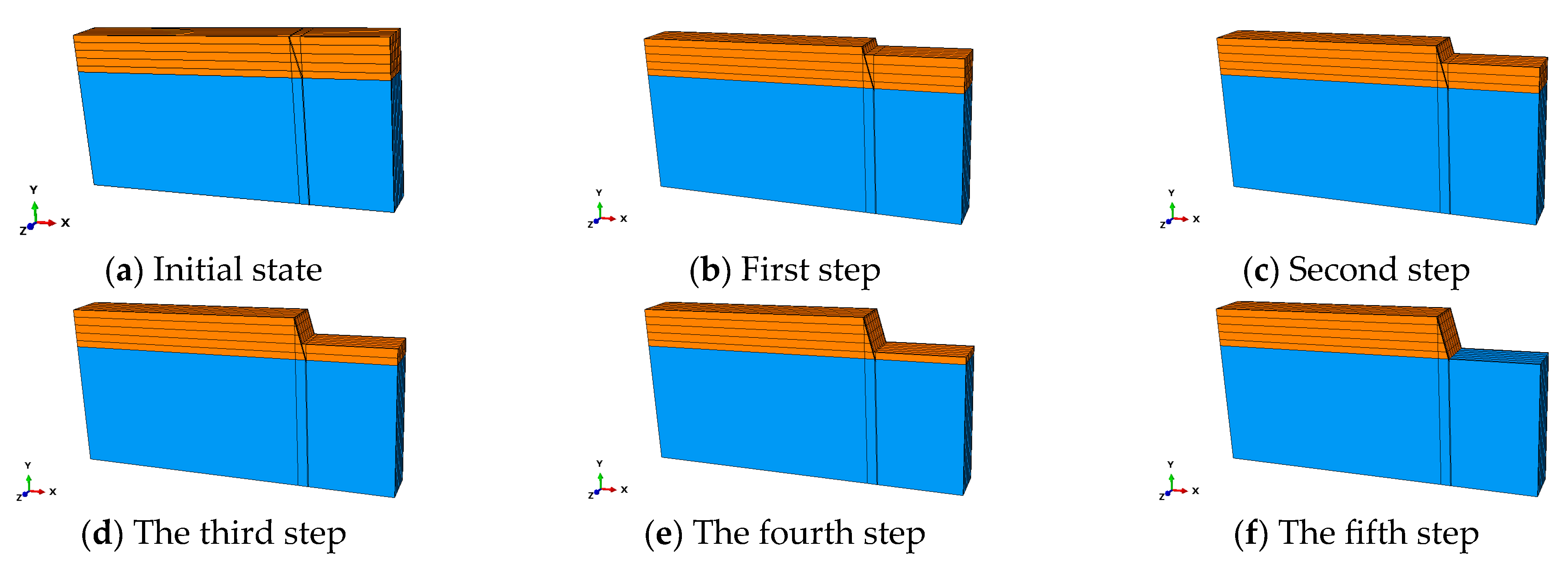
4.3. Construction Steps
During the excavation of the foundation pit, the interactive mode of model change is used to kill the soil nail unit first and complete the assignment of the ground stress field in the soil. Subsequently, the soil of the excavation part is killed in turn, and the loess-based composite slurry soil nail unit of the corresponding layer is activated to simulate the excavation of the soil and the penetration of the loess-based composite slurry soil nail. The specific process is shown in
Figure 12.
5. Analysis of Numerical Simulation Results
5.1. Finite Element Analysis of Construction Stage
The above foundation pit is divided into 5 steps for excavation. In order to study the variation law of excavation horizontal displacement, soil nailing stress and safety factor in the construction stage of loess-based composite slurry soil nailing wall supporting foundation pit, the material selection of soil nailing and surface layer of loess-based composite slurry is considered according to the elastic–plastic material. To calculate the elastic modulus of the soil nailing and surface layer of loess-based composite slurry, the compressive strength of the slurry at 14 days of age, with 35% moisture content and an 18% cement mixing ratio, is selected.
Table 5 displays the elastic modulus and Poisson’s ratio for the soil nailing and surface layer of the loess-based composite slurry.
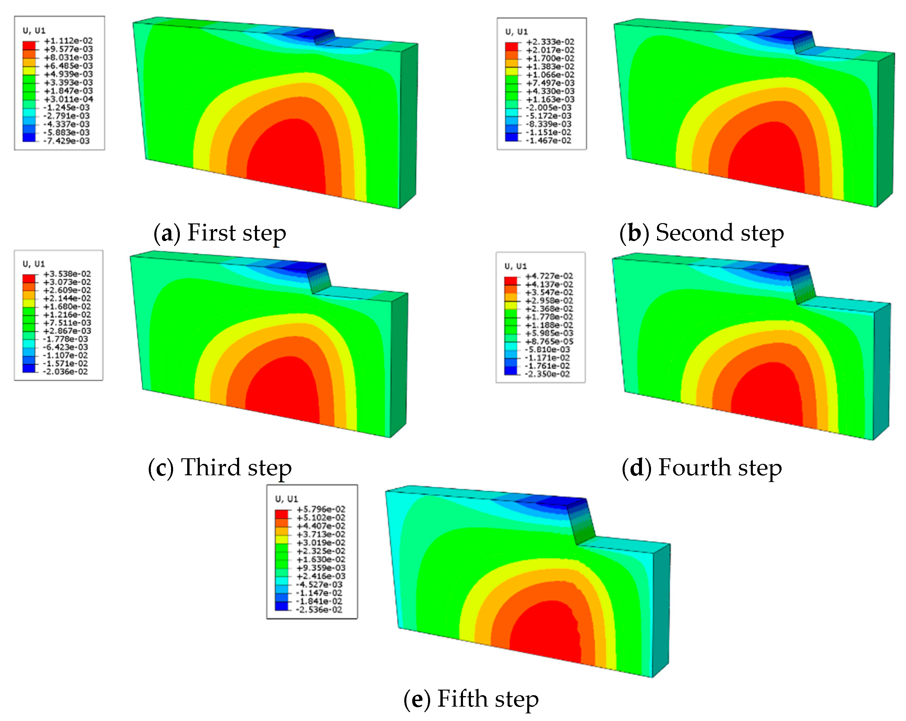
5.1.1. Horizontal Displacement Analysis of Excavation
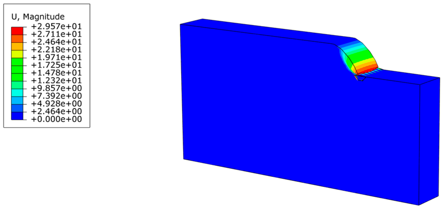
Figure 13 illustrates the displacement contour map for the construction stage, while
Table 6 presents the horizontal displacement at the top of the slope during this stage. As the soil nails are implanted and the excavation depth increases, the horizontal displacement at the top of the Step-2 slope grows by 97.47% in comparison to the Step-1 slope top. The displacement at the top of Step-3 slope rose by 38.79% relative to Step-2, while the displacement at the top of Step-4 slope was 15.42% higher than that of Step-3. Finally, the horizontal displacement at the top of Step-5slope increased by 7.91% compared to Step-4. This shows that as the foundation pit is excavated, the horizontal displacement at the slope’s top progressively rises. However, the growth rate gradually decreases, which is because the loess-based composite slurry supporting foundation pit plays a certain role. With the increasing depth of the foundation pit excavation, the effectiveness of the loess-based composite slurry soil nailing wall in providing support also improves.
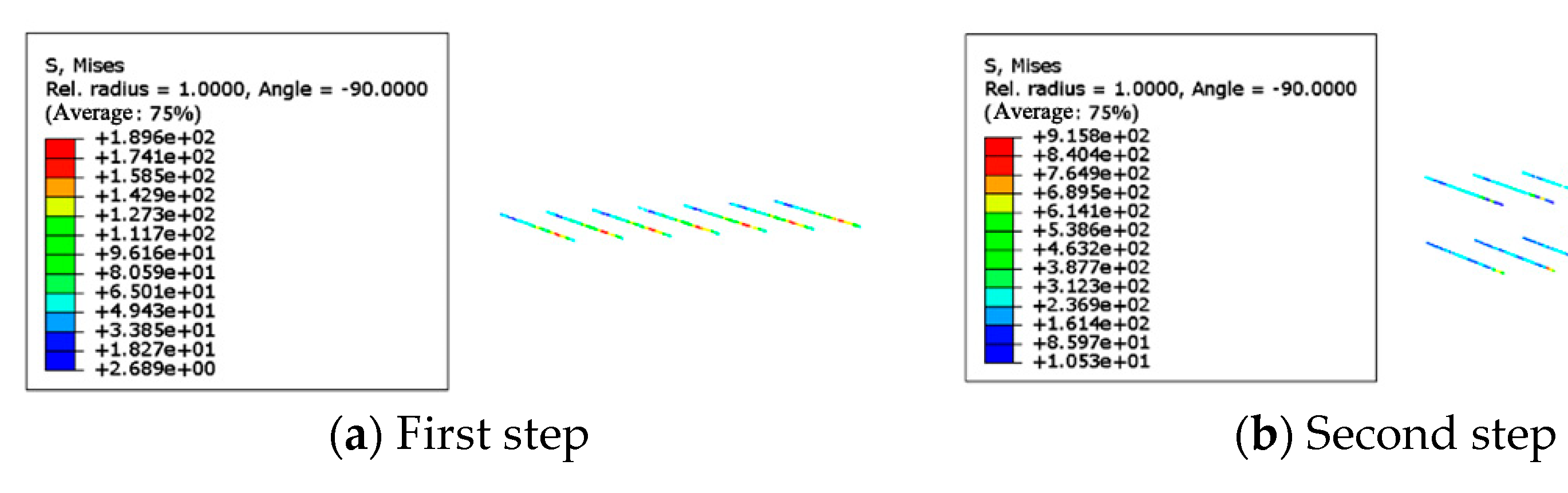
5.1.2. Soil Nail Stress of Loess-Based Composite Slurry
Figure 14 shows the stress distribution across each row of soil nails after excavation. While
Table 7 presents the maximum stress values of the soil nails during the construction phase. As shown in
Table 7, the load carried by loess-based composite slurry soil nails increases with the excavation depth. This is due to the gradual unloading of the soil as excavation progresses, which results in a corresponding rise in horizontal load. The soil nails of loess-based composite grout participate in the work and bear most of the horizontal load through the stress transfer between the soil and the soil. In the supporting structure of the loess-based composite slurry soil nailing wall, the loess-based composite slurry soil nail integrates with the surrounding soil to create a unified composite system. This composite significantly improves the compression modulus of the soil. This greatly enhances the shear strength and failure strength of the soil, allowing the structure to efficiently manage the deformation of the foundation pit.
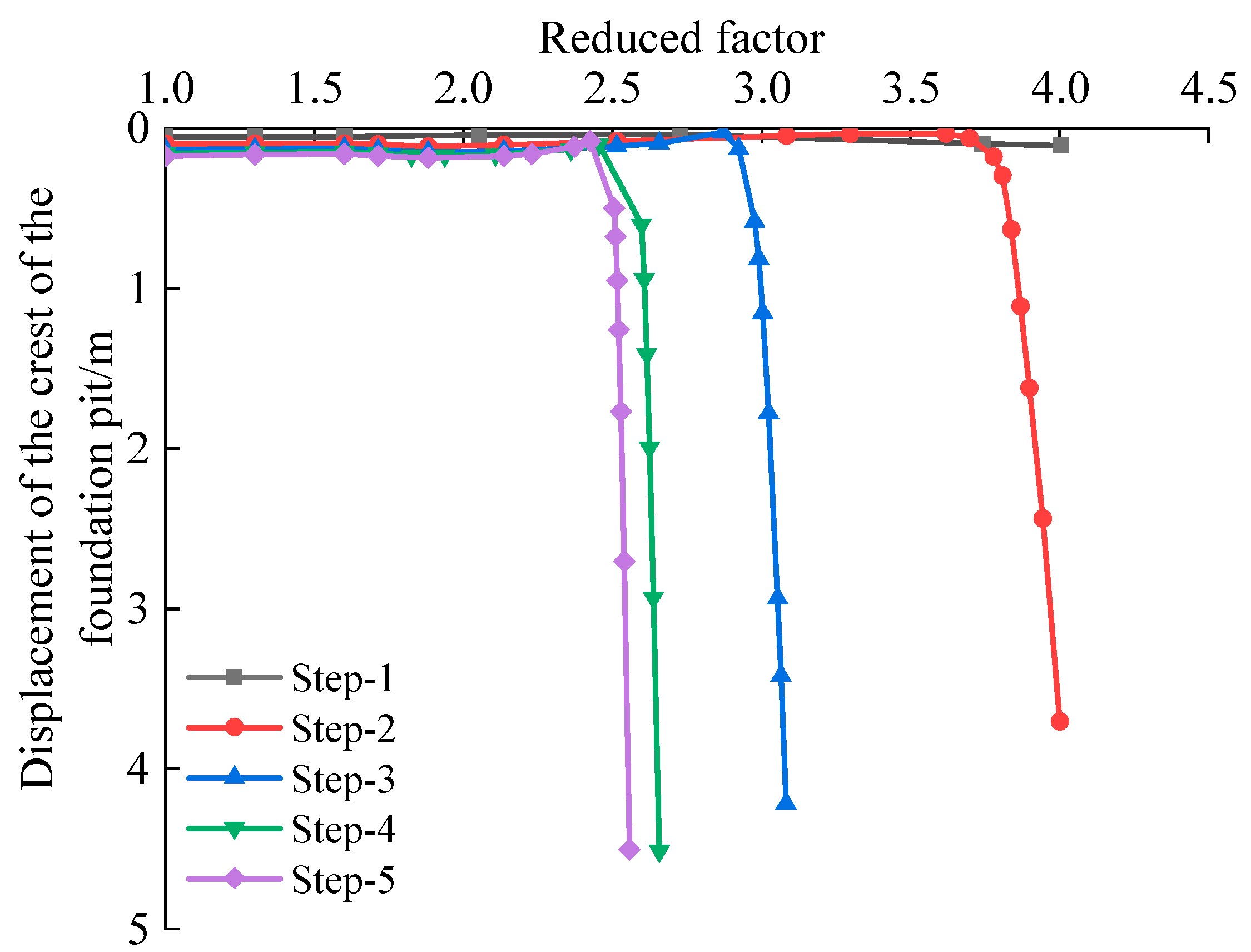
5.1.3. Safety Factor
The safety factor of the foundation pit, after completing all five stages of excavation, has not yet been determined. This is conducted to analyze how the reduction coefficient varies during the excavation process. The results are presented in
Figure 15.
It can be found from
Figure 15 that with the increase of the reduction coefficient, the displacement of the slope top is basically unchanged. When the reduction coefficient increases to a certain value, the displacement of the slope top increases sharply. This is because the soil strength is insufficient, the stiffness is reduced, the soil enters the softening state, and the supporting structure fails. The soil loses sufficient support force, resulting in increased displacement. It can be seen from
Figure 16 that the landslide occurred in the foundation pit, and the reduction coefficient of the inflection point was taken as the safety factor of the foundation pit. From
Table 8, it can be seen that the safety factor of the foundation pit decreases with the excavation of the foundation pit, but the magnitude of the decrease is also shrinking, tending to converge to a certain value. The calculation results show that the loess-based composite slurry soil nailing support structure has a high safety degree of foundation pit slope, and the safety factor finally converges to about 2.4.
6. Conclusions
In this paper, the foundation pit support of loess-based cement slurry soil nailing wall is carried out. The research investigates the variations in surface displacement and the axial force of soil nails throughout the excavation and loading processes. The numerical simulation of a foundation pit in the Lanzhou area is carried out. The soil nailing stress of loess-based cement slurry and the safety factor of the foundation pit are analyzed by the finite element method. The conclusions drawn are as follows:
As the foundation pit depth grows, the displacement of the surface layer of the loess-based cement slurry initially increases before decreasing. The maximum displacement occurs at the middle depth, showing a change rule of large at both ends and small in the middle.
In the excavation phase, the axial force at the center of each row of soil nails is higher than at the ends, with this force rising as the excavation depth increases. During the loading phase, as the soil nail depth increases, the axial force decreases. At first, the axial force changes slowly, but there is a noticeable rise in the middle and later stages of loading.
As the depth of loess-based composite slurry soil nailing and excavation increases, the horizontal displacement at the top of the slope rises gradually, though the rate of increase slows down over time.
As excavation depth increases, the safety factor of the foundation pit decreases, but the decreasing range is also shrinking. The calculation results indicate that the foundation pit, reinforced with a loess-based composite slurry soil nailing wall, demonstrates a high level of safety, and the safety factor finally converges to about 2.4.
Author Contributions
Conceptualization, Z.L.; methodology, S.Y.; Validation, S.Y.; Investigation, Z.G.; Data curation, X.L.; resources, S.Y.; writing—original draft, Z.L. and X.L.; writing—review and editing, S.Y. and Z.G. All authors have read and agreed to the published version of the manuscript.
Funding
This research was funded by the Gansu province science plan project (key research and development plan-industry) (Grant No. 23YFGA0083), the Qinghai key R&D and transformation plan project (Grant No. 2024-0204-SFC-0069).
Data Availability Statement
Some or all data, models, or code that support the findings of this study are available from the corresponding author upon reasonable request.
Conflicts of Interest
Authors Zhao Long and Zhiyuan Guo were employed by the company Gansu CSCEC Municipal Engineering Investigation and Design Institute Co., Ltd. The remaining authors declare that the research was conducted in the absence of any commercial or financial relationships that could be construed as a potential conflict of interest.
References
- Li, Y.; Zhang, S.; Ye, X.; Liu, W.; Shi, Y.; Li, R.; Tian, B. Field pull-out tests for soil nail prepared by different grouting techniques. J. Cent. South Univ. (Sci. Technol.) 2024, 55, 2690–2700. [Google Scholar] [CrossRef]
- Wang, H.; Zhang, R.; Zheng, J.; Song, X.; Yang, T.; Wu, G. Numerical analysis of an enhanced flexible reinforcement system for expansive soil slopes based on on-site validation. Bull. Eng. Geol. Environ. 2024, 83, 337. [Google Scholar] [CrossRef]
- Villalobos, S.A.; Villalobos, F.A. Effect of nail spacing on the global stability of soil nailed walls using limit equilibrium and finite element methods. Transp. Geotech. 2021, 26, 100454. [Google Scholar] [CrossRef]
- Dong, J.; Lian, B.; Liu, G.; Wu, X.; Shi, L. In-situ test study on weak slope reinforcement with lime nail composite anchors. J. Basic Sci. Eng. 2024, 32, 527–545. [Google Scholar]
- Zhi, B.; Zhang, Q.; Zhang, H.; He, J.; Liang, D.; Liang, G.; Li, H. Model test study on failure mechanism of soil nailing wall in loess area. Bull. Eng. Geol. Environ. 2022, 81, 295. [Google Scholar] [CrossRef]
- Yazdandoust, M.; Mollaei, R.; Askari, F. Failure mechanisms and strain-dependent parameters of helical soil-nailed walls under seismic conditions. Int. J. Geomech. 2024, 24, 04024051. [Google Scholar] [CrossRef]
- Bayat, M.; Emadi, A.; Kosariyeh, A.H.; Kia, M.; Bayat, M. Collapse fragility analysis of the soil nail walls with shotcrete concrete layers. Comput. Concr. 2022, 29, 279–283. [Google Scholar]
- Bayesteh, H.; Behjatpour, V. Distinct-Element Modeling of the Use of Reinforced Shotcrete Facings for Soil–Nail Retrofitting of Masonry Retaining Walls. J. Perform. Constr. Facil. 2025, 39, 04025015. [Google Scholar] [CrossRef]
- Mohamed, M.H.; Ahmed, M.; Mallick, J. An Experimental Study of Nailed Soil Slope Models: Effects of Building Foundation and Soil Characteristics. Appl. Sci. 2021, 11, 7735. [Google Scholar] [CrossRef]
- Jalota, S.; Tangri, A. Comparative study of various flexible facing materials for soil nailed slopes. Mater. Today Proc. 2022, 49, 2342–2347. [Google Scholar] [CrossRef]
- Guo, Y.; Wu, H.; Li, C. The Influence of Pile-Driving Vibration on the Soil Nailing Support of a Silty Soil Foundation Pit. Adv. Civ. Eng. 2021, 2021, 6651169. [Google Scholar] [CrossRef]
- Shoar, S.M.S.; Salehzadeh, H. Investigation of Failure Behaviour of Soil Nailed Excavations under Surcharge by Centrifuge Model Test. KSCE J. Civ. Eng. 2023, 27, 66–79. [Google Scholar] [CrossRef]
- Ramteke, P.C.; Sahu, A.K. Reliability assessment of soil nailed slopes under surcharge loading: A numerical and experimental investigation with theoretical aspects. J. Appl. Reg. Geol./Z. Dtsch. Ges. Geowiss. (ZDGG) 2024, 175, 147. [Google Scholar] [CrossRef]
- Ehrlich, M.; Rosa, C.A.B.; Mirmoradi, S.H. Effect of construction and design factors on the behaviour of nailed-soil structures. Proc. Inst. Civ. Eng.-Geotech. Eng. 2022, 175, 618–630. [Google Scholar] [CrossRef]
- Momeni, M.; Moghimi, E.; Nassiri, M.; Hajari, F.; Mirassi, S. Evaluating of optimal length and spacing of nails in stabilization of soil pits using finite element and limit equilibrium methods. Geomech. Eng. 2024, 39, 593–609. [Google Scholar]
- Won, M.S.; Sadiq, S.; Seo, S.U.; Park, J.Y. Numerical investigation of gravity-grouted soil-nail pullout capacity in sand. Open Geosci. 2023, 15, 20220543. [Google Scholar] [CrossRef]
- Sabermahani, M.; Nuri, H. Studying the effect of geometrical nail layout on the performance of soil-nailed walls: Physical and numerical modeling. Acta Geodyn. Geomater. 2021, 18, 45. [Google Scholar] [CrossRef]
- Gui, M.-W.; Rajak, R.P. A Numerical Study of a Soil-Nail-Supported Excavation Pit Subjected to a Vertically Loaded Strip Footing at the Crest. Buildings 2024, 14, 927. [Google Scholar] [CrossRef]
Figure 1.
Flow chart of model test.
Figure 1.
Flow chart of model test.
Figure 2.
Soil nail bar body diagram.
Figure 2.
Soil nail bar body diagram.
Figure 3.
Loess-based cement slurry surface layer.
Figure 3.
Loess-based cement slurry surface layer.
Figure 4.
Curves of surface layer displacement of loess-based cement slurry changing with depth.
Figure 4.
Curves of surface layer displacement of loess-based cement slurry changing with depth.
Figure 5.
The axial force variation curve of the first row of soil nails in the excavation stage.
Figure 5.
The axial force variation curve of the first row of soil nails in the excavation stage.
Figure 6.
The variation curve of the axial force of the second row of soil nails in the excavation stage.
Figure 6.
The variation curve of the axial force of the second row of soil nails in the excavation stage.
Figure 7.
The variation curve of the axial force of the third row of soil nails in the excavation stage.
Figure 7.
The variation curve of the axial force of the third row of soil nails in the excavation stage.
Figure 8.
The variation curve of the axial force of the first row of soil nails in the loading stage.
Figure 8.
The variation curve of the axial force of the first row of soil nails in the loading stage.
Figure 9.
The axial force variation curve of the second row of soil nails in the loading stage.
Figure 9.
The axial force variation curve of the second row of soil nails in the loading stage.
Figure 10.
The variation curve of the axial force of the third row of soil nails in the loading stage.
Figure 10.
The variation curve of the axial force of the third row of soil nails in the loading stage.
Figure 11.
Geometric model diagram.
Figure 11.
Geometric model diagram.
Figure 12.
Schematic diagram of the construction process.
Figure 12.
Schematic diagram of the construction process.
Figure 13.
Displacement contour map.
Figure 13.
Displacement contour map.
Figure 14.
Soil nail stress diagram.
Figure 14.
Soil nail stress diagram.
Figure 15.
Slope top displacement–reduction coefficient in different construction stages.
Figure 15.
Slope top displacement–reduction coefficient in different construction stages.
Figure 16.
Displacement after a landslide.
Figure 16.
Displacement after a landslide.
Table 1.
Soil material parameters.
Table 1.
Soil material parameters.
| Material | Elastic Modulus (MPa) | Poisson’s Ratio | Internal Friction Angle (°) | Cohesion (kPa) |
|---|
| Soil-1 | 20 | 0.3 | 32 | 23 |
| Soil-2 | 40 | 0.3 | 40 | 0 |
Table 2.
Table of yield strength of loess-based composite slurry soil nail.
Table 2.
Table of yield strength of loess-based composite slurry soil nail.
| Time (d) | Moisture Content | Cement Mixing Ratio | Loess-Based Composite Slurry-Soil Bond Strength (kPa) | Soil Nail Yield Strength (kPa) |
|---|
| 14 | 35% | 18% | 25.06 | 25.06 |
Table 3.
Calculation table of elastic modulus of loess-based composite slurry soil nail.
Table 3.
Calculation table of elastic modulus of loess-based composite slurry soil nail.
| Number | Cement Mixing Ratio | Compressive Strength (kPa) | Elastic Modulus (MPa) |
|---|
| 351214 | 12% | 906.15 | 8025 |
| 351814 | 18% | 1891.48 | 10,422 |
| 352414 | 24% | 3021.67 | 12,865 |
| 353014 | 30% | 5520.05 | 17,340 |
Table 4.
Elastic modulus calculation table of the supporting surface layer.
Table 4.
Elastic modulus calculation table of the supporting surface layer.
| Number | Cement Mixing Ratio | Compressive Strength (kPa) | Elastic Modulus (MPa) |
|---|
| 351214 | 12% | 906.15 | 2469 |
| 351814 | 18% | 1891.48 | 4866 |
| 352414 | 24% | 3021.67 | 7309 |
| 353014 | 30% | 5520.05 | 11,784 |
Table 5.
Soil nailing wall material parameter table.
Table 5.
Soil nailing wall material parameter table.
| Material | Elastic Modulus (MPa) | Poisson’s Ratio | Nail Soil Bond Strength (kPa) |
|---|
| Soil nails | 10,422 | 0.2 | 25.06 |
| Jet surface layer | 4866 | 0.18 | / |
Table 6.
Horizontal displacement of the slope top in the construction stage.
Table 6.
Horizontal displacement of the slope top in the construction stage.
| Construction stage | Step-1 | Step-2 | Step-3 | Step-4 | Step-5 |
| Slope top horizontal displacement (cm) | 0.7429 | 1.467 | 2.036 | 2.350 | 2.53 |
| Growth rate | _ | 97.47% | 38.79% | 15.42% | 7.91% |
Table 7.
The maximum stress of the soil nail in the construction stage.
Table 7.
The maximum stress of the soil nail in the construction stage.
| Construction stage | Step-1 | Step-2 | Step-3 | Step-4 | Step-5 |
| The maximum stress of soil nail (MPa) | 0.1896 | 0.9158 | 3.108 | 6.018 | 6.830 |
Table 8.
Safety factor in the construction stage.
Table 8.
Safety factor in the construction stage.
| Construction stage | Step-1 | Step-2 | Step-3 | Step-4 | Step-5 |
| Safety factor | 4 | 3.771 | 2.923 | 2.452 | 2.431 |
| Disclaimer/Publisher’s Note: The statements, opinions and data contained in all publications are solely those of the individual author(s) and contributor(s) and not of MDPI and/or the editor(s). MDPI and/or the editor(s) disclaim responsibility for any injury to people or property resulting from any ideas, methods, instructions or products referred to in the content. |
© 2025 by the authors. Licensee MDPI, Basel, Switzerland. This article is an open access article distributed under the terms and conditions of the Creative Commons Attribution (CC BY) license (https://creativecommons.org/licenses/by/4.0/).


