1. Introduction
The subgrade is a crucial foundation for high-speed railway track structures, enduring dynamic train loads and being affected by hydrological and climatic changes [
1]. To meet the strength and deformation control requirements during operation, the design code TB 10621-2014 mandates the improvement of the upper roadbed layer with graded gravel, specifying criteria for material properties, particle-size distribution, compaction quality, permeability, and frost resistance. Mud pumping [
2,
3] typically occurs when the subgrade-surface material softens and extrudes as slurry through the track system owing to adverse combinations of soil, water, and train loads [
4]. This phenomenon primarily affects general-speed ballasted railway subgrades [
5] composed of clay or silty clay with a liquid limit > 32% and a plasticity index > 12. Using coarse fills with high strength and water stability effectively controls mud pumping in such ballasted-track subgrades [
6,
7].
In recent years, mud pumping in ballastless (slab-track) subgrades has become a significant issue for high-speed railways under extreme rainfall conditions [
8]. Fine particles from graded gravel mix with water to form slurry, which extrudes from structural joints—transverse expansion joints between adjacent base slabs and longitudinal side joints between the shoulder capping layer and the concrete base. Severe cases create local voids beneath the concrete base, affect track geometry [
9] and compromise long-term stability. Specifically, fines slurry extruded from cracks alters the contact and support conditions between the concrete base and the roadbed surface, endangering safe train operation.
Current research on slab-track mud pumping primarily focuses on the physical and mechanical impacts of slurry extrusion on the track structure and on related remedial measures [
10]. However, the causes of mud pumping are mostly qualitatively inferred from empirical observations, and quantitative simulations covering the entire hydraulic–mechanical process are lacking. Moreover, the stability of roadbed-surface particles under rainfall in different climatic regimes requires further investigation [
11]. At present, there is no quantitative design method that links regional rainfall statistics to subgrade structure and drainage optimization for proactively preventing mud pumping in slab tracks.
To address these limitations, this study introduces the Rain-Intensity-Ponding (RIP) method, a framework for quantitatively assessing mud pumping in slab tracks [
12]—a system distinct from ballasted tracks because of its rigid concrete base and absence of a ballast layer. Unlike prior studies focused on ballasted tracks [
6,
7], the RIP method uniquely integrates regional rainfall patterns, crack geometry, and dynamic load cycles to predict ponding duration as a precursor to mud pumping. By correlating ponding duration with a threshold number of train-axle passes, the method bridges hydraulic and mechanical factors and enables climate-specific drainage design [
13], thereby advancing the resilience of high-speed rail infrastructure.
The remainder of the paper is organized as follows.
Section 2 describes the dynamic physical-model tests and develops the RIP formulation.
Section 3 applies the method to a representative intercity railway in Eastern China, converting intensity–duration–frequency (IDF) curves into ponding duration and axle-pass metrics.
Section 4 presents the proposed hydraulic design strategies—permeable shoulders, fines-controlled graded gravel, and blind-ditch drainage—and verifies their performance through parametric analysis.
Section 5 summarizes the key findings, highlighting their implications for sustainable and climate-resilient slab-track design and outlining directions for large-scale field validation and AI-assisted monitoring.
2. Physical Modeling and Hydraulic Method
To address the unique subgrade issues of slab track foundations in rainy regions, this section begins by elucidating the formation mechanism of mud pumping through dynamic load model tests. This is followed by a comprehensive hydraulic analysis, which includes developing the RIP method for identifying slurry extrusion and evaluating the current drainage capacity of slab track subgrades. The subsections cover the physical modeling of mud pumping, criteria for rainfall infiltration and surface ponding, and hydraulic analysis of seepage paths within the track structure.
2.1. Physical Modeling of Mud Pumping in Slab Track Roadbed
Field investigations of operational high-speed lines have revealed that beneath slab tracks, there often exists a gap between the concrete base and the roadbed surface. This gap formation is attributed to several factors, including inherent defects in the concrete base, differential deformation between the base and subgrade induced by train loading, and deformation and settlement of the foundation due to the self-weight of the overlying layers. These factors collectively cause a loss of adhesion between the concrete base and the subgrade, resulting in the observed gaps [
14,
15].
When the concrete undergoes shrinkage deformation due to thermal stresses, the fill material within the expansion joints of the base [
16] and the lateral joints with the shoulder capping layer tend to crack, forming water infiltration paths. Given that the roadbed surface beneath the concrete base is flat and the shoulder capping layer is higher than the roadbed surface in the current design, lateral drainage is hindered. Poor permeability in graded gravel restricts drainage. Rainwater then accumulates within the structural gaps beneath the concrete base.
Under train loads [
17], the structural layers above and below the gap move in opposite directions, causing the free water within the gap to be compressed, generating high instantaneous hydraulic pressure, which dissipates through the water seepage cracks in the base. The pressure differential between the gap and the cracks induces seepage flow, causing fine particles to migrate within the graded gravel due to the seepage force (denoted as
, where
is the water unit weight [kN·m
−3],
is the hydraulic gradient [–],
V is the particle volume [m
3]), forming a muddy slurry. Repeated cycles of rising and dissipating dynamic water pressure lead to the extrusion of this slurry from the base cracks, manifesting as mud pumping in the foundation.
Physical model tests (
Figure 1) on a compacted gravel layer overlying a permeable layer (representing the upper roadbed system) were conducted under various conditions, including different fines content, moisture levels (unsaturated, saturated with and without surface ponding), load patterns, and slit width between the load plate and the gravel surface (
Table 1). Details of the test protocols are provided in [
14]. The objective of these tests was to identify the fundamental driving factors for fines migration mobilization in the railway sub-structure beneath slab tracks.
While prior research on mud pumping predominantly focused on ballasted tracks (e.g., [
2,
3]), this study specifically addresses ballastless slab tracks, which exhibit distinct failure mechanisms due to rigid concrete base interactions. Unlike Huang et al. [
18], who investigated pore pressure in full-scale models, our physical model introduces strain-controlled slit simulation to replicate concrete base detachment, a critical factor unique to slab tracks. Additionally, this work systematically evaluates the combined effects of fines content, hydraulic conditions, and slit width—parameters not comprehensively analyzed in earlier studies on ballastless systems. Although typical field values remain under 10%, the wider range (0–20%) provides insight into the sensitivity of mud pumping severity to fines content.
Table 1.
Test parameters and alignment with real-world railway conditions.
Table 1.
Test parameters and alignment with real-world railway conditions.
| Parameter | Test Range/Value | Alignment with Real Conditions |
|---|
| Fines Content | 0% (F0), 20% (F20) | Based on field surveys of graded gravel in high-speed railway subgrades [19]; typical in situ fines content usually remains below 10% |
| Moisture Conditions | Unsaturated (R), saturated with ponding (P), saturated without ponding (S) | Reflects standard drainage performance classifications: excellent (R), moderate (P), and poor (S) according to TB 10621–2014 guidelines [20] |
| Load Patterns | Stress-controlled (sinusoidal), strain-controlled (slit simulation) | Stress amplitudes (25–30 kPa) match train-induced dynamic loads [19]; strain-controlled simulation replicates observed concrete base detachment phenomena [14,19] |
| Slit Width | 1.23–3.45 mm | Gap widths align closely with field-measured gaps ranging from 1 to 4 mm, caused by thermal deformation under typical seasonal temperature variations (ΔT = 15 °C) [14,19] |
| Cyclic Frequency | Up to 10 Hz | Corresponds directly to train operating speeds of 200–350 km/h, consistent with standard operating conditions of high-speed railways |
All key test parameters—including fines content, moisture conditions, gap widths, and cyclic loading patterns—were derived directly from comprehensive field observations and surveys of operational slab track railway subgrades. Parameters were chosen specifically to replicate realistic field conditions as documented in [
19] and field investigations referenced in TB10621-2014. This ensured that experimental setups closely mirrored actual scenarios rather than hypothetical assumptions, enhancing the practical applicability and accuracy of the study’s findings.
Several conclusions can be drawn: Mud pumping does not occur in the absence of gaps between the concrete base and the subgrade surface, regardless of the moisture content in the graded gravel. In this scenario, the train load transmitted by the upper track structure is primarily borne by the high-strength graded gravel particles [
21], and the increased pore water pressure between the particles does not cause soil particle movement. Even when the graded gravel is moist, and there is a gap, mud pumping does not occur. No seepage flow occurs between the gap and the subgrade surface, and there is no seepage force to induce soil particle migration [
22].
Mud pumping becomes apparent when there is ponding and load is applied to the graded gravel with gaps. Tests showed gap heights > 3 mm amplify fines migration severity by approximately 40% compared to smaller gaps, clearly indicating a nonlinear sensitivity to gap height. Under load, the gap volume compresses, and the accumulated water in the gap seeps through the subgrade surface, causing erosion and movement of surface particles due to sufficient seepage force. The higher the gap, the greater the volume compression, and at the same loading frequency, the faster the erosion flow, resulting in greater seepage force and earlier mud pumping.
When graded gravel is saturated but has no ponding, mud pumping severity increases with gap height, eventually leading to localized mud pumping. If the gap height is small, there is no accumulated water and no erosion flow, so fines migration is not significant. As the gap height increases, the load on the soil increases; if the groundwater level remains constant, significant vertical deformation accumulates on the soil surface, gradually leading to ponding under load and causing mud pumping.
The severity of mud pumping intensifies with higher fine content in the graded gravel. The critical seepage force required for particle movement is proportional to particle size; higher fine content in the graded gravel results in more particles moving under the same seepage force, exacerbating mud pumping. Physical model tests demonstrate that gap formation, water accumulation within the gap, and train loading are the three fundamental elements for slurry extrusion in slab track subgrades. All three conditions must be present for mud pumping to occur.
2.2. Mein–Larson Rainfall Infiltration Under Extreme Rainfall and Surface Ponding Criteria
Having identified gap formation as a key factor, this subsection quantifies rainwater infiltration using the Mein–Larson model.
The volume of water infiltrated per unit area of soil over a given period is termed the infiltration amount, denoted as
Fs. The rate of change of
Fs over time
t, known as the infiltration rate, is represented as
fc = d
Fs/d
t. The infiltration capacity under conditions of ample water supply is denoted as
fp. Based on the assumption of a homogeneous soil mass with uniform initial water content and sufficient water supply, the typical ponding infiltration equation is derived from Darcy’s Law [
23].
Here, ks is the soil’s saturated hydraulic conductivity; H0 is the surface ponding depth; Hi is the matric suction head at the wetting front; θi is the initial water content of the soil; θs is the saturated water content of the soil. As the wetting front infiltration distance zw or the infiltration amount Fs increases, fp exhibits a negative power function decrease. When zw or Fs increases to infinity, fp approaches ks.
Based on the Green–Ampt Infiltration model [
24], Mein and Larson [
25] analyzed the infiltration process under steady rainfall conditions and derived the surface ponding criterion for rainfall infiltration. Surface ponding occurs only when the rainfall intensity exceeds the soil’s infiltration capacity, resulting in an excess water supply. Rainfall intensity (
I) is defined as the average depth of rainwater per hour (mm/h) derived from local IDF curves provided by regional meteorological services. Assuming a constant rainfall intensity throughout the rainfall duration, the actual soil infiltration rate and surface ponding status can be considered under two scenarios:
Scenario 1: I ks—According to Equation (1), when the rainfall intensity is less than or equal to the minimum soil infiltration capacity, all rainwater is absorbed by the soil, and no surface ponding occurs during the entire rainfall period. The actual soil infiltration rate equals the rainfall intensity, i.e., fc = I.
Scenario 2: I > ks—In the initial phase of rainfall infiltration, with small zw and Fs, corresponding to fp I > ks, no surface ponding occurs, and fc = I. As zw and Fs increase, when ks < fp ≤ I, surface ponding occurs, and the entire soil undergoes ponded infiltration, fc = fp.
In Scenario 2, before ponding, the soil still undergoes downward saturated infiltration. According to the rule that
fp decreases with increasing
Fs, the actual infiltration rate before ponding is always
fc =
I. The critical rainfall intensity
Ic required for surface ponding under rainfall duration
t is ultimately determined by
fc =
fp =
I, as shown in Equation (2). For coarse fill commonly used in high-speed railway subgrades, the small matric suction affects
Ic only in the early stages of rainfall duration, with
Ic rapidly approaching
ks as
t increases.
The Mein–Larson and Green–Ampt models reveal that critical rainfall intensity (Ic) and saturated permeability (ks) are key parameters determining infiltration behavior and ponding duration on slab track subgrades. While Ic calculation methodology is general, specific values require regional calibration due to variations in soil permeability, rainfall patterns, and climate conditions.
2.3. Hydraulic Analysis for Seepage Paths in Track Structure
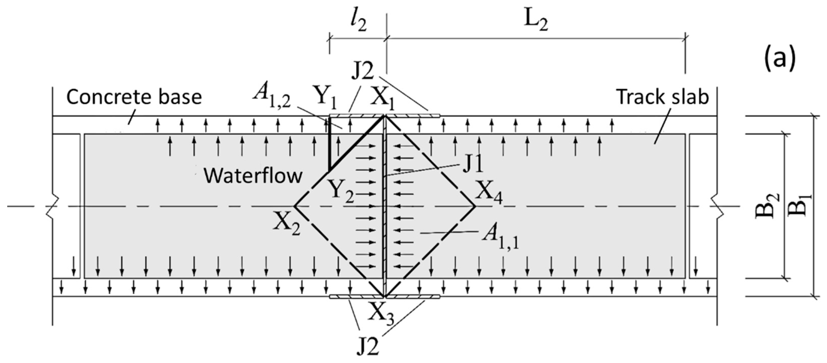
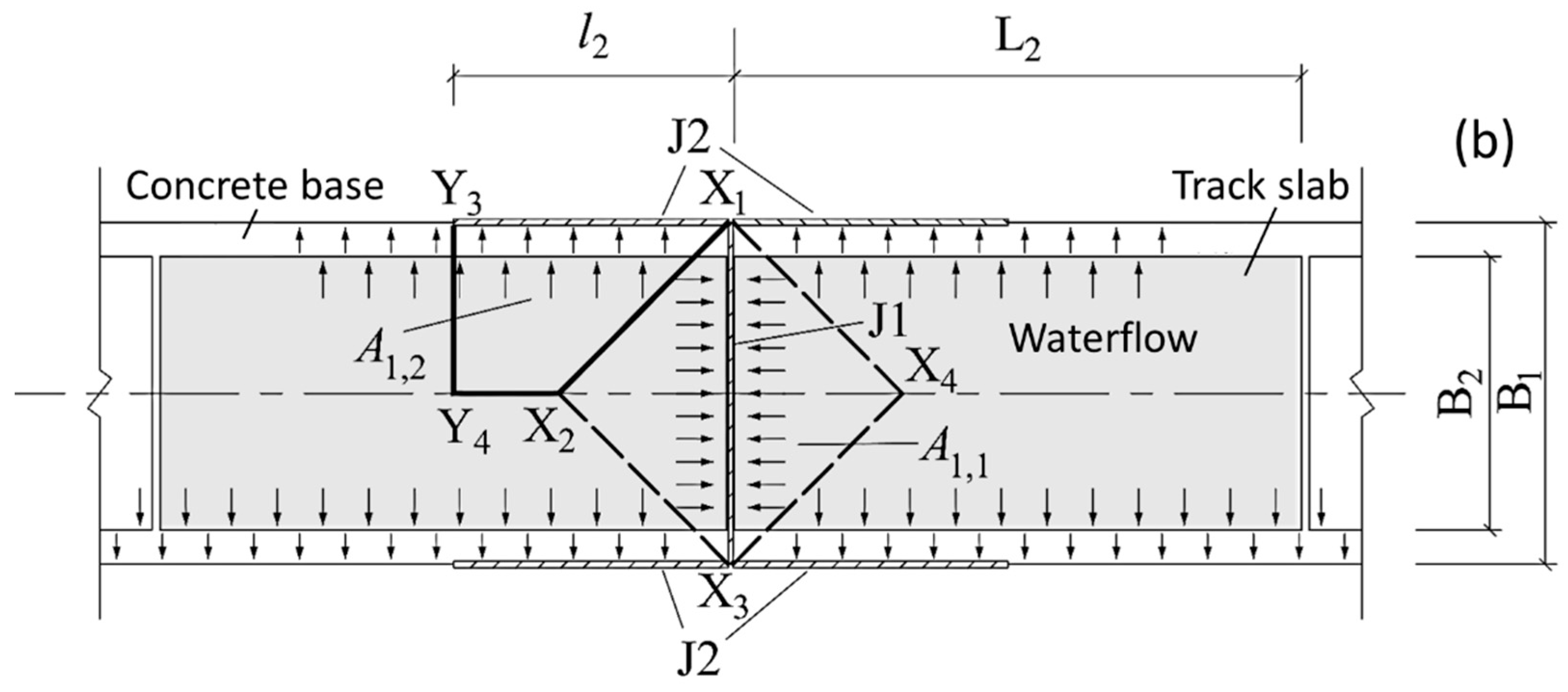
The impermeable concrete material over the slab track substructure directs most rainwater falling on the track structure to be discharged laterally through the top surface. Only the filling materials in the expansion joints or side joints of the base may provide water seepage paths. Generally, the longitudinal joints of the track base show minor mud pumping, with severe slurry extrusion occurring mainly near the end sections of the segmented base where stress is concentrated, and the joints become visible. Mud and water frequently erupt from the expansion joints and adjacent longitudinal side joints. Therefore, hydraulic calculations focus on the gaps in the mud pumping area at the ends of each concrete base. The seepage amount through seepage paths during rainfall is related to the rainwater catchment of the gaps and their permeability:
2.3.1. Rainwater Catchment Flow in Cracks
The regional rainfall intensity pattern is typically depicted by an I − t curve, which uses the duration of rainfall as the horizontal axis and the maximum average rainfall intensity for each duration as the vertical axis. The determined I − t relationship is influenced by the geographical location and the recurrence period T of the rainfall event. In a given area, the I value decreases gradually with the increase in t for a specific T.
Assuming the dimensions of the base and track slab (length × width) are
L1 ×
B1 and
L2 ×
B2, respectively, if the mud pumping crack
J1 appears along the entire width of the base,
J1 length is taken as
l1 =
B1, and the lengths of the surrounding adjacent fines migration side joints
J2 are
l2, with
l2 always less than 0.5
L1. As shown in
Figure 2, the rainwater primarily gathers on the surface of the track slab and its adjacent base surfaces. Assuming the rainwater on the catchment surface flows only to the nearest base edge, the catchment area
A1,
1 of
J1 is a square
X1X2X3X4 with one diagonal as the base expansion joint, and the catchment area
A1, 2 of
J2 depends on the length
l2. When
l2 ≤
B1/2, it is considered as △
X1Y1Y2 in
Figure 2a, and when
l2 >
B1/2, it is considered as trapezoid
X1Y3Y4X2 in
Figure 2b.
During rainfall, ignoring the runoff time on the catchment surface, the catchment flow into the fractures is the product of the catchment area and rainfall intensity, calculated by:
Here, Qc,1 is the catchment flow of crack J1; Qc,2 is the catchment flow of crack J2.
2.3.2. Seepage Flow in Cracks
The seepage flow in a single crack exhibits different motion characteristics depending on the flow pattern. Typically, the Reynolds number (
Re) in Equation (5) distinguishes between laminar and turbulent flow within the crack. For laminar flow dominated by viscous forces with
Re < 2300, the unit length seepage flow rate (
q) in a smooth crack is proportional to the first power of the hydraulic gradient (
J) and the cube of the crack width (
e), following the classical cubic law. When
Re ≥ 2300, inertial forces increase, transitioning the flow to a turbulent state, and the cubic law no longer applies. In this case, the ratio of
q to
becomes a nonlinear empirical function of e, as shown in Equation (6). Assuming the flow of rainwater in the seepage cracks of the track structure base approximates the seepage law of smooth cracks, the water flow rate in the crack under a certain hydraulic gradient
J will not exceed
Qf, defined by Equation (7) as the flow rate determined by the crack’s permeability.
Here, l is the length of the crack, ν is the kinematic viscosity of water (ν = 1.007 × 10⁻⁶ m2/s at 20 °C), and g is the gravitational acceleration (g = 9.8 m/s2). Crack geometry and permeability flow (Qf) significantly influence rainwater infiltration paths and ponding at slab track joints, which is crucial for mud pumping onset assessment.
2.4. Determination of Mud Pumping from Ponding Duration in Slits
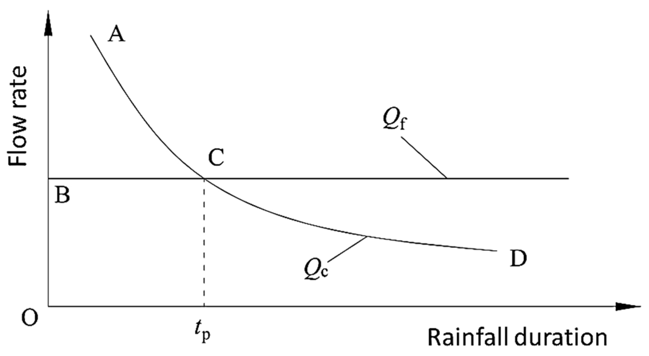
From Equations (3) and (4), it can be observed that under a fixed rainfall recurrence period, if the track structure dimensions and crack lengths are known, the catchment flow rate
Qc for a single crack varies with the rainfall duration
t following the regional rainfall intensity pattern, as shown by curve AD in
Figure 3. If
Qc remains less than the inherent permeability flow rate
Qf throughout the entire rainfall duration, then the seepage flow rate
Qin in into the crack equals
Qc. Conversely, as depicted by the broken line (BCD) in
Figure 3, if
Qc exceeds
Qf for a duration
t <
tp, the excessive rainfall catchment exceeds the crack’s permeability capacity, and rainwater can only infiltrate the crack at
Qin =
Qf. Once t
t >
tp and
Qc falls below
Qf,
Qin becomes controlled by
Qc again. Thus,
Qin at any rainfall duration is determined by the smaller value between
Qc and
Qf.
Assuming the water seeping through cracks
J1 and
J2 uniformly percolates vertically into the mud-pumping subgrade surface, the ratio of the total seepage flow rate through cracks to the mud-pumping area, defined as the equivalent rainfall intensity
Ie on the subgrade surface can be expressed as
Here, Qin,i is the seepage flow rate at Crack I; Qc,i is the catchment flow rate at Crack i, calculated using Equation (3) or (4) for different crack locations; Qf,i is the permeability flow rate at Crack i, determined by Equations (6) and (7) based on the value of Re; A2 is the area of the mud-pumping region on the subgrade surface.
Considering the infiltration characteristics of the subgrade soil under the concrete base primarily determined by the upper roadbed fills when the equivalent rainfall intensity
in the mud-pumping area exceeds the critical rainfall intensity
of the upper roadbed fill material, the subgrade surface’s water supply conditions surpass the fill material’s infiltration capacity, leading to water accumulation at the joint. Therefore, the ratio
F(
t) of
Ie(
t) to
Ic(
t) at any rainfall duration
t under the specified rainfall recurrence period [
T] serves as the criterion for water accumulation at the joint:
Here, F(t) is the rainfall intensity ratio at the subgrade surface, with F(t) > 1 indicating water accumulation at the joint; Ie(t) is the equivalent rainfall intensity at duration t; Ic(t) is the critical rainfall intensity of the surface fill material at duration t.
If the duration interval
F(
t) > 1 is [t
1, t
2] (where 0 ≤
t1 ≤
t2< + ∞), the duration
td of water accumulation at the joint can be calculated by
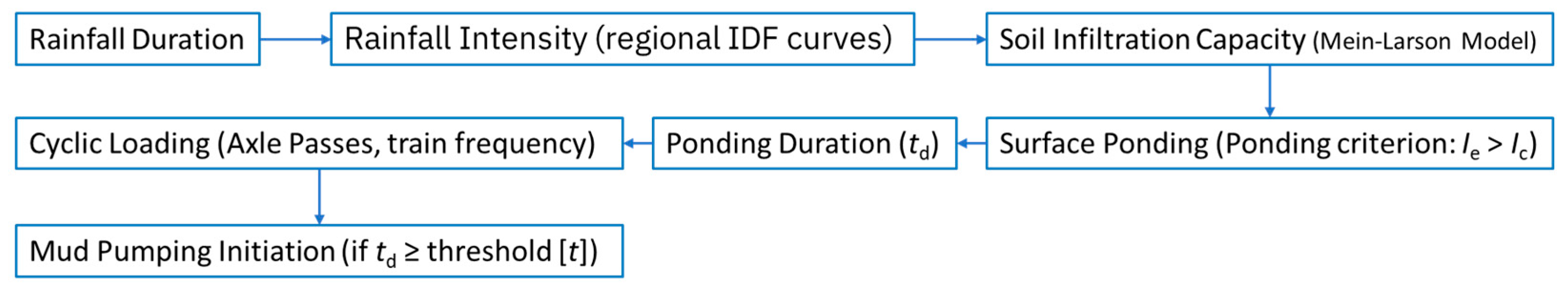
Analysis combining Equations (2)–(10) reveals that
td is primarily influenced by the saturated permeability coefficient of the upper roadbed fill material, regional rainfall intensity, and crack geometrical dimensions. The smaller the saturated permeability coefficient and the larger the rainfall intensity and crack dimensions, the longer the duration of water accumulation at the joint. During railway operation, prolonged water accumulation at the joint can lead to subgrade mud pumping under repeated train load applications. A criterion for determining mud pumping in slab track subgrades termed the RIP method can be proposed based on whether
td exceeds the threshold accumulation time [
t] for mud pumping formation:
Here, [t] is the threshold accumulation time for mud pumping formation, determined by factors such as the type of fill material, joint height, number of load cycles forming mud pumping, train formation, train speed, and train tracking time.
While the Mein–Larson rainfall infiltration model is derived under static hydraulic conditions, the dynamic effects of train loads are incorporated via the ponding duration
td. This duration determines the number of load cycles [
t] (Equation (11)) that the subgrade undergoes during water accumulation. Specifically,
td acts as a bridge between static infiltration (governed by rainfall intensity and soil permeability) and dynamic loading effects (train-induced seepage forces). For instance, in
Section 3, the Eastern China case demonstrates that
td = 90 min corresponds to 440 axle passes (critical threshold [
t] = 52.56 min), validating that prolonged ponding amplifies mud pumping under repeated dynamic loads. Thus,
td quantifies the interaction between hydraulic stagnation and mechanical fatigue, enabling proactive mud pumping identification in slab tracks. The RIP method quantifies this hydro-mechanical coupling for predictive assessment (
Figure 4).
3. Design Example and Verification
Taking an intercity railway in Eastern China as a typical example of mud pumping, the RIP method was employed to assess the occurrence of fines migration and water accumulation in the gaps of the CRTS-I ballastless track. In the upper layer of the intercity railway roadbed, the graded gravel contained up to 10% of particles smaller than 0.1 mm. Based on the relationship between the fine content of graded gravel and permeability coefficient [
14], the corresponding
k10 value is 7.02 × 10
−3 mm/s, then
θi is 4.8%,
θs is 6.1%, and
Hi is 500 mm.
To contextualize the subsequent climate and infiltration analysis, the geometric parameters of the track structure are detailed as follows: The track structure dimensions are
L1 = 20 × 10
3 mm,
B1 = 3000 mm,
L2 = 4962 mm, and
B2 = 2400 mm. Field investigations revealed that mud pumping predominantly occurred within a 5 m longitudinal range centered on the expansion joint of a concrete base, corresponding to
A2 = 15 × 10
6 mm
2. The lengths of water seepage cracks
J1 and
J2 in this area are
l1 = 3000 mm and
l2 = 2500 mm, respectively. As shown in
Figure 2b, the total catchment area of the cracks equals the mud pumping area.
The axle-pass threshold of 440 passes within 90 min, as applied to the intercity railway, was derived from operational schedules involving trains consisting of six motor cars and two trailers, operating at intervals of approximately four minutes during peak rainfall events. Rainfall intensity data used in this analysis were sourced from the Shanghai Meteorological Bureau, specifically employing regional intensity–duration–frequency (IDF) curves that define rainfall intensity as the average depth of rainwater per unit time (mm/h). These IDF curves were utilized to calculate the equivalent rainfall intensity and subsequent ponding durations critical for evaluating mud pumping potential using the RIP method.
The long-term temperature observations [
26] of ballastless tracks concluded that the concrete base temperature reached extremes in winter and summer, with a variation amplitude of approximately 30 °C. Considering that mud pumping in the intercity railway subgrade typically occurs in March and April, when rainfall is abundant, and temperatures are moderate, the example considers a base temperature variation range Δ
T = 15 °C. The temperature-induced crack width of the joint fill material is calculated according to:
Here, α is the coefficient of linear expansion, α1 for concrete is 1.0 × 10⁻⁵ °C−1, α2 for asphalt concrete is 2.1 × 10⁻⁵ °C−1; Lx is the structural dimension corresponding to thermal shrinkage deformation. The calculation results of crack width in mud pumping areas reveal that the widths of cracks are 3.00 mm and 0.54 mm for J1 and J2, respectively, given that the horizontal width of the asphalt concrete capping layer is taken as 2000 mm.
For the free infiltration state of
J = 1.0, combining Equations (10)–(12) yields the water flow rate corresponding to the turbulent flow for crack
J1 at width
e1 = 3.00 mm as
Qf1 = 9.64 × 10
8 mm
3/min, and for crack
J2 at
e2 = 0.54 mm under laminar flow as
Qf2 = 1.92 × 10
7 mm
3/min. Using the urban rainstorm intensity formula for the Shanghai area under the standard [
T] = 1a as the rainfall intensity
I1 along the intercity railway,
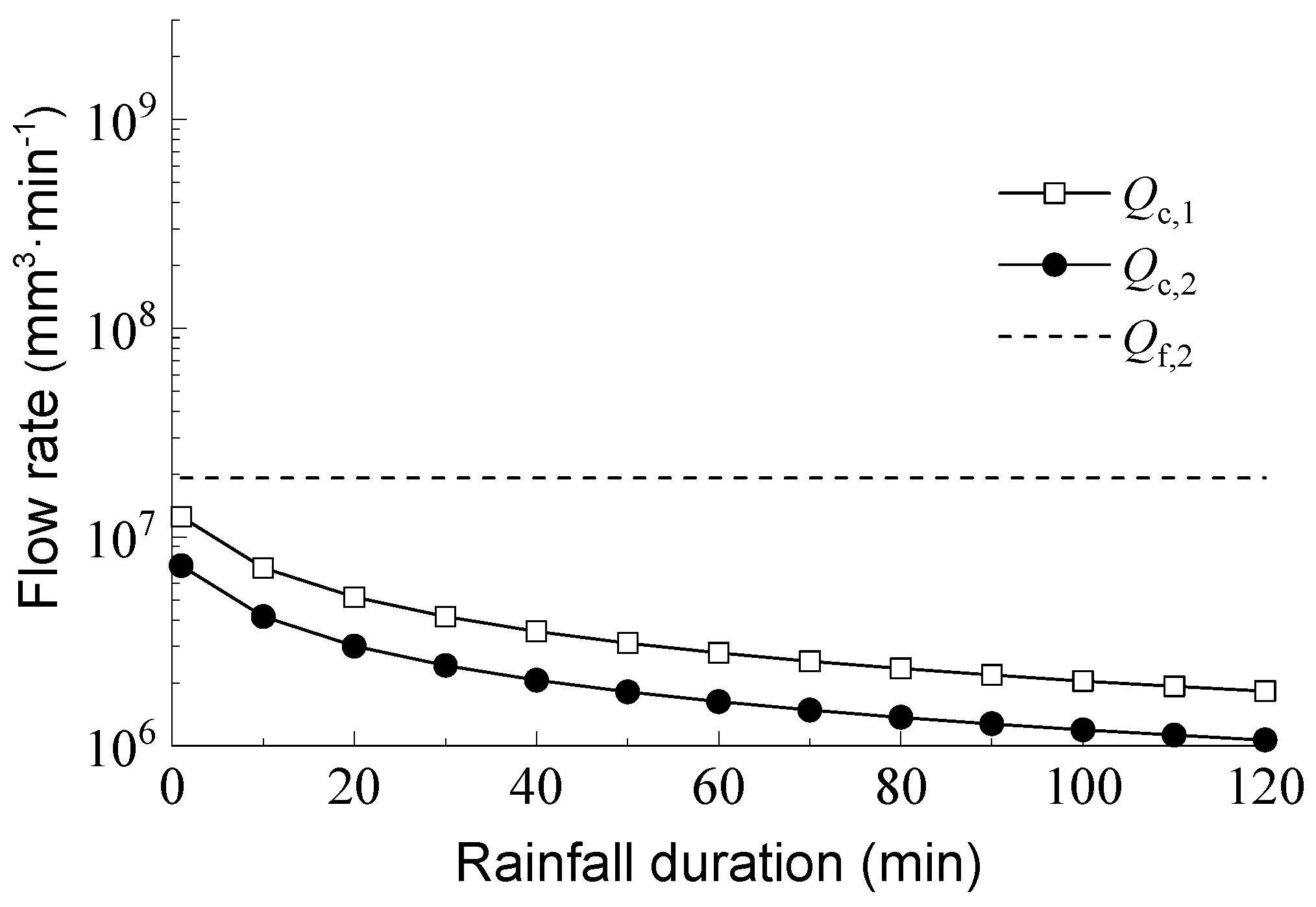
Figure 5 shows the variation in the collected water flow rates
Qc,1 and
Qc,2 for cracks
J1 and
J2 over time. Throughout the duration, the collected water flow rates for
J1 and
J2 are less than their respective flow rates, and the equivalent rainfall intensity
Ie,1 on the roadbed surface is determined solely by the rainwater collected by the cracks. Assuming the total catchment area of the seepage cracks equals the mud pumping area, according to Equation (8),
Ie,1 is equivalent to the atmospheric rainfall intensity,
.
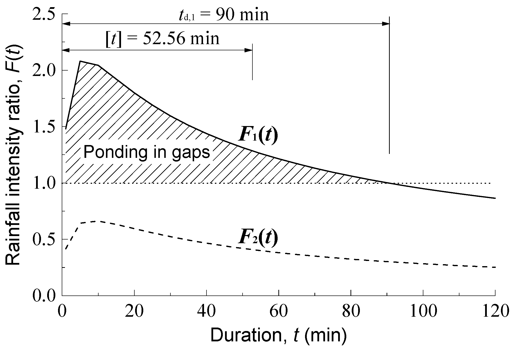
Combining Equations (2), (8) and (9),
Figure 6 illustrates the rainfall intensity ratio
F1(
t) of the roadbed surface of the intercity railway under various rainfall durations, comparing it with the rainfall intensity ratio
F2(
t) of Lanzhou City, characterized by a semi-arid climate, under the same conditions (corresponding
I2 for [
T] = 1a is given as
). Lanzhou’s climate, with 1-year return rainfall < 300 mm, provides a control to validate the model’s sensitivity to regional rainfall patterns. The inclusion of Lanzhou, a region with contrasting rainfall patterns, demonstrates the model’s adaptability to diverse climatic conditions, reinforcing its robustness. This demonstrates how regional climatic differences impact ponding duration.
The ponding duration directly translates into the number of axle passes during which the subgrade experiences cyclic loading, establishing a clear hydro–mechanical relationship critical to mud pumping onset. In the initial stage of rainfall infiltration, the critical rain intensity Ic,g for water accumulation in the graded gravel quickly approaches the saturated permeability coefficient k10, causing F1(t) and F2(t) to increase briefly with time; when t > 10 min, Ic,g remains stable, and F1(t) and F2(t) exhibit a negative correlation with time due to the control of rainfall intensity alone. Using the iterative method, the duration interval for F1(t) > 1.0 is [0, 90], and the corresponding ponding duration td,1 = 90 min is derived from Equation (11); F2(t) remains below 1.0 throughout the duration, indicating that 1-year return rainfall will not cause ponding on the roadbed surface of the high-speed railway in Lanzhou, with td,2 = 0. The intercity railway in Eastern China validates the RIP method against field-observed mud pumping issues, where prolonged ponding (td,1 = 90 min) aligns with recurrent slurry extrusion at expansion joints. Conversely, Lanzhou’s semi-arid climate serves as a negative control (td,2 = 0), demonstrating the method’s adaptability to diverse rainfall regimes. This contrast underscores the method’s utility in identifying regions where subgrade design mismatches climatic demands. While our analysis used standard 1-year return rainfall, further research must incorporate scenarios of increased climatic variability and extreme storms to validate RIP under changing climate conditions.
The intercity railway operates at 300 km/h, with trains comprising 6 motor cars and 2 trailers (total length: 201.4 m). At 4 min intervals, this results in 15 trains/h, subjecting the subgrade to 440 axle passes within the critical ponding duration [
t] = 52.56 min [
14]. Under the 1d recurrence rainfall conditions, analysis by the RIP method indicates that for the intercity railway upper roadbed layer, constructed with graded gravel containing 10% fines,
td,1 exceeds [
t] by 71.2%, causing the roadbed ponding duration to surpass the permissible value. During this period, repeated train loads can cause fines migration [
27] within the compacted fill due to water erosion, contributing to the severe mud pumping issues observed during operation in rainy climates. Under the same conditions, the
td,2 = 0.0 in the semi-arid region of Lanzhou suggests that the infiltration capacity of graded gravel with 10% fines can accommodate the 1-year return rainfall intensity in that region. Therefore, in the design and construction of high-speed railway slab track foundations, it is crucial to strictly control the fines in graded gravel to ensure that the critical rain intensity determined by its permeability coefficient exceeds the effective rain intensity on the roadbed surface in the area. This axle-pass threshold is region-specific; railways in drier climates, like Lanzhou, exhibit significantly lower thresholds, demonstrating the criticality of regional calibration.
4. Optimized Design of Roadbed Drainage in Rainy Regions
The roadbed surface beneath the concrete base is flat, while the roadbed surface outside the base area is sealed with asphalt concrete. During rainfall, due to the limitations of a flat surface and the water-blocking effect of the capping layer, rainwater entering the gaps between the base and the roadbed surface cannot be discharged laterally. Instead, it must percolate vertically and flow out through the anti-seepage drainage layer installed at the bottom of the upper roadbed. Enhancing the infiltration and drainage capacity of the roadbed structure, ensuring that rainwater entering the gaps does not accumulate for long periods, and preventing the simultaneous occurrence of the three driving factors for mud pumping can effectively avoid slurry extrusion defects.
During rainfall, the infiltration flow rate of rainwater entering the gaps from the concrete base cracks is determined by the smaller value between the catchment flow rate in the relevant catchment area of the cracks and the cracks’ own water flow rate. It has been confirmed that an increase in the fine content within graded gravel will result in a reduced saturated permeability coefficient [
14]. According to the Green–Ampt infiltration model [
24], the infiltration capacity of the upper roadbed will decrease accordingly. Therefore, in the design and construction of new rail lines, the control of the fine content in graded gravel should ensure that the infiltration capacity of the upper roadbed exceeds the infiltration flow rate per unit area in the gap area of the roadbed surface, ensuring that ponding at the gaps infiltrates quickly and does not accumulate on the roadbed surface for extended periods.
Rainwater that infiltrates vertically from the roadbed surface into the upper roadbed layer should be discharged from the subgrade within a short time through drainage measures, preventing long-term accumulation of rainwater within the fill material and on the roadbed surface due to insufficient drainage capacity.
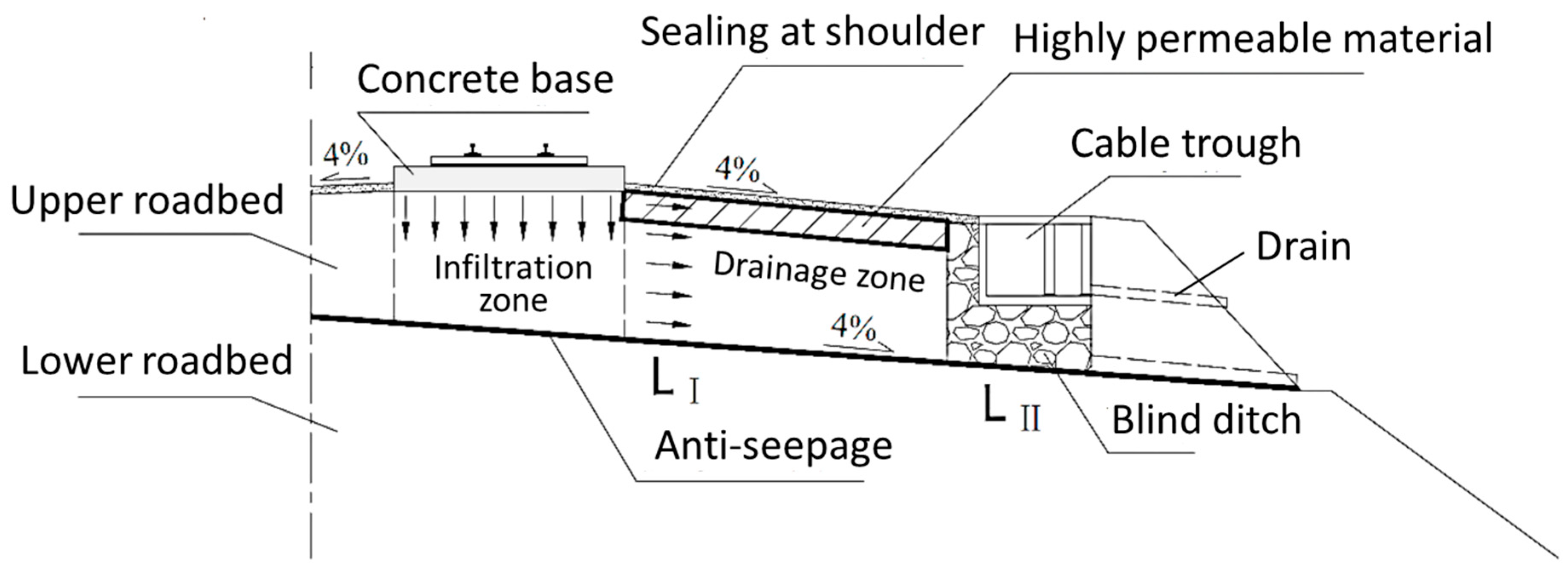
4.1. Verifying Drainage Capacity of Current Slab Track Roadbed
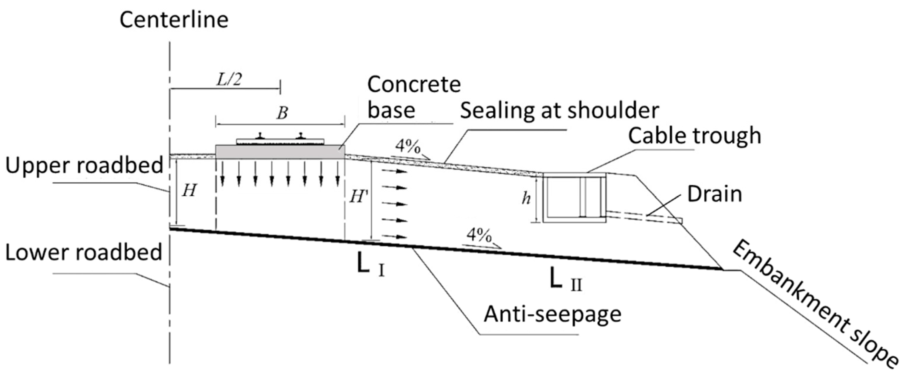
The current drainage measures for slab track beds in China involve setting a 4% “herringbone” transverse drainage slope at the interface between the upper and lower roadbeds and installing an anti-seepage drainage layer across the entire section. The principle of slab track foundation drainage is illustrated in
Figure 7, which divides the entire seepage cross-section from rainwater entry to discharge from the roadbed surface into two parts: the infiltration zone and the drainage zone.
For the
infiltration zone, under the most unfavorable conditions, the initial infiltration surface is assumed to be the roadbed surface within the width of the base. Neglecting the thickness of ponding water and the matric suction head of the graded gravel, the maximum infiltration rate in the upper roadbed is approximately equal to the saturated permeability coefficient of the graded gravel
k. Thus, the maximum infiltration flow rate
Qin per unit longitudinal length of the upper roadbed is given by
Here, B is the width of the concrete base.
For the drainage zone, vertically infiltrated water reaches the anti-seepage drainage layer at the bottom of the upper roadbed and flows out of the subgrade through the transverse drainage slope, permeable materials in the anti-seepage drainage layer, and the graded gravel under the shoulder capping layer. As shown in
Figure 7, there are two typical drainage cross-sections at the shoulder cable trough: (a) the cross-section from the inner shoulder capping layer to the bottom of the upper roadbed (L
I); (b) the cross-section from the bottom of the cable trough to the bottom of the upper roadbed (L
II). Therefore, the maximum outflow rate per unit longitudinal length of the corresponding drainage cross-sections is
Here, Qout,1 is the maximum outflow rate of drainage cross-section I; Qout,2 is the maximum outflow rate of drainage cross-section II; i is the slope of the transverse drainage at the contact surface between the upper and lower roadbeds; H′ is the thickness of the graded gravel under the roadbed capping layer; θr is the hydraulic conductivity of the anti-seepage drainage layer; h is the height of the cable trough; H is the thickness of the graded gravel under the subgrade centerline; L is the spacing between lines; ks,j is the permeability coefficient of the jth layer of permeable material in the anti-seepage drainage layer; dj is the thickness of the jth layer of permeable material in the anti-seepage drainage layer.
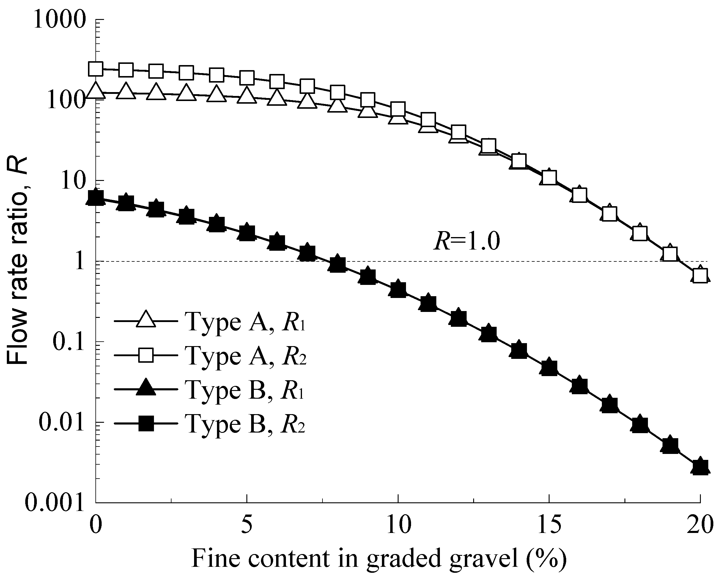
The anti-seepage drainage layer commonly found at the bottom of the upper roadbed typically consists of “geomembrane + medium-coarse sand” or “composite drainage board + medium-coarse sand”. The permeability coefficient of graded gravel is significantly influenced by its fine content, which in turn affects the
Qin,
Qout,1, and
Qout,2 of the upper roadbed. Therefore,
Figure 8 presents the ratios of infiltration to outflow rates
R1 and
R2 (where
R1 =
Qin/
Qout,1 and
R2 =
Qin/
Qout,2) for different fine contents in graded gravel. Type A represents the “geomembrane + medium-coarse sand” anti-seepage drainage layer, where the geomembrane serves as the water barrier and the medium-coarse sand as the permeable material. Based on empirical experience, the thickness of the medium-coarse sand
d1 is 50 mm, with a corresponding permeability coefficient
ks,1 = 1 × 10
−1 mm/s. Type B represents the “composite drainage board + medium-coarse sand” anti-seepage drainage layer, with the same thickness and permeability coefficient for the medium-coarse sand as in Type A. The composite drainage board provides both barrier and drainage functions, with a planar permeability coefficient of
ks,2 = 150 mm/s and a drainage thickness of
d2 = 8 mm.
Figure 8 shows that for the “geomembrane + medium-coarse sand” anti-seepage drainage layer, the permeability of graded gravel with low fine content is comparable to that of medium-coarse sand, though the gravel layer is significantly thicker. The drainage capacity of the drainage zone is controlled by the granular layer. As the shoulder cable trough occupies part of the graded gravel thickness, the cross-sectional area of Section II is smaller than that of Section I, resulting in
R2 >
R1. When the fine content exceeds 13%, the permeability of graded gravel decreases significantly, with most water draining through the medium-coarse sand in the anti-seepage drainage layer, causing
R1 and
R2 to be similar. Additionally, when fine content falls within 0–19%,
R1 and
R2 are always greater than 1.0, indicating that the drainage capacity of the “geomembrane + medium-coarse sand” is significantly less than the infiltration capacity of the upper roadbed. Consequently, rainwater vertically infiltrating from the concrete base cannot promptly flow out of the drainage layer, leading to prolonged accumulation in the upper roadbed and on its surface.
For the “composite drainage board + medium-coarse sand” anti-seepage drainage layer, the high permeability rate of the composite drainage board primarily determines the drainage capacity of the drainage zone. The impact of the shoulder cable trough on the graded gravel cross-section can be ignored, and R1 remains close to R2. Moreover, when fine content is less than 7%, R1 and R2 are both greater than 1.0, but when fine content is greater than 7%, R1 and R2 are both less than 1.0. This indicates that replacing the geomembrane with a highly permeable composite drainage board allows the “composite drainage board + medium-coarse sand” to meet the drainage capacity requirements of the upper roadbed composed of graded gravel with more than 7% fines. However, for graded gravel with higher permeability and less than 7% fines, the infiltration rate (Qin) of the infiltration zone still exceeds the outflow rates Qout,1 and Qout,2 of the drainage zone.
4.2. Optimized Drainage Design with Permeable Shoulders
To prevent mud pumping in slab track foundations in rainy regions, it is recommended to reduce the fine content in graded gravel to increase the vertical infiltration rate, ensuring that rainwater entering the gaps at the ends of concrete bases does not accumulate for extended periods. The Code for Design of Railway Earth Structure (TB10001-2016) imposes strict requirements on the fine content of graded gravel, specifying that the fine content measured by the washing method for Type-II graded gravel should not exceed 3% and should not exceed 5% after compaction, allowing rapid drainage of water from the granular mass. However, as shown in
Figure 8, increasing the permeability coefficient of graded gravel results in
Qin exceeding
Qout,1 and
Qout,2, indicating that the current drainage capacity is insufficient to handle the infiltration capacity of the upper roadbed. Merely enhancing the infiltration capability of graded gravel without improving the drainage function of the upper roadbed still poses a risk of prolonged water accumulation at the gaps between the track and foundation, potentially leading to mud pumping.
For typical fines migration locations in unit slab track roadbeds, an optimized drainage design method featuring a permeable shoulder is proposed to enhance the drainage performance of slab track subgrades. The optimized drainage design mandates reducing fines in graded gravel (<7%) and replacing shoulder capping materials with high-permeability fill (
ka > 23 mm/s), coupled with drainage blind ditches to enhance lateral outflow by 70–90% (originate from parametric model calculations validated by lab tests [
14]) under 1-year rainfall recurrence. It includes two primary aspects.
4.2.1. Replacement of Subgrade Fill Under Shoulder Capping Layer
As shown in
Figure 9, before constructing the shoulder capping layer (asphalt concrete) outside the track concrete base, replace the graded gravel to a certain depth beneath this capping layer with highly permeable materials. After replacement, the maximum outflow rate
Q′
out,1 for drainage cross-section I of the upper roadbed drainage zone is given by
Here, da is the replacement depth of graded gravel under the shoulder capping layer, and ka is the permeability coefficient of the replaced highly permeable material.
To ensure that
Q′
out,1 >
Qin, given a predetermined replacement depth
da, the permeability coefficient
ka of the permeable material under the capping layer must meet the following condition:
Here, ka,min is the minimum permeability coefficient of the replaced highly permeable material. If ka,min ≤ k, only setting an anti-seepage drainage layer at the bottom of the upper roadbed meets the drainage capacity requirements without replacing the fill material.
If the permeability coefficient
ka of the permeable material is predetermined and
ka >
k, the replacement depth
da must meet the following condition:
Here, da,min is the minimum replacement depth of the permeable material. If da,min ≤ 0, no fill material replacement is required.
4.2.2. Design of Blind Ditch Under Cable Trough
Due to the cable trough occupying part of the upper roadbed thickness, to increase the maximum outflow rate
Q′
out,2 of drainage cross-section II, a drainage blind ditch should be installed from the cable trough to the bottom of the upper roadbed. The
Q′
out,2 changes to:
Here, kg is the permeability coefficient of the blind ditch filling material.
To ensure that
Q′
out,2 >
Qin, the permeability coefficient of the drainage blind ditch filling material must satisfy the condition:
Simultaneously, to ensure the continuity of water flow near the contact surface between the blind ditch and the graded gravel, the overlap length
Lg of the blind ditch material with the graded gravel should meet the following condition:
Based on field survey data [
15], the area within 5 m longitudinally from the end of the base expansion joint is a severe mud pumping zone for unit slab tracks. Therefore, along the track’s longitudinal direction, the permeable shoulder should be installed at intervals of no less than 5 m centered on the end of the base slab.
Compared with the current railway subgrade drainage standard (TB10621-2014), the RIP method provides a more systematic approach that directly integrates regional rainfall intensity–duration–frequency (IDF) statistics with train axle-load thresholds. Current guidelines primarily rely on empirical drainage criteria and generic permeability requirements without explicitly accounting for the dynamic interaction between rainfall, subgrade infiltration, and cyclic train loading. Traditional ballast-based drainage systems also differ significantly from slab track systems due to their higher permeability, inherent drainage capabilities through ballast voids, and flexible structural interface. In contrast, slab tracks exhibit rigid interfaces and limited drainage paths, making them susceptible to prolonged ponding under extreme rainfall. Thus, the RIP method uniquely addresses these vulnerabilities by quantitatively linking hydraulic conditions to mechanical loading thresholds, ensuring targeted and proactive drainage designs specifically suited to slab track infrastructure.
While the proposed RIP method offers a predictive framework for ponding-induced mud pumping, several assumptions apply. The model assumes homogeneous upper roadbed fills and steady rainfall infiltration without considering groundwater interaction or anisotropic permeability. Dynamic effects are integrated via ponding duration rather than full hydro-mechanical coupling. Compared to empirical design thresholds used in Code TB10621–2014, this method introduces site-specific calibration based on regional rainfall and crack geometry. It differs from ballast-based studies (e.g., ref. [
6]) by focusing on structural interfaces unique to slab tracks.
4.3. Application
A high-speed railway in a rainy region uses a CRTS-I type unit slab track. The track structure concrete base width is
B = 3 m, the spacing between the double-track lines is
L = 5 m, and the cable trough height is
h = 300 mm. The upper roadbed surface is proposed to be filled with graded gravel with a fine content of 0%, and a transverse drainage slope with a gradient
i = 0.04 is set at the bottom of the upper roadbed. The anti-seepage drainage measures use a combination of composite drainage board and medium-coarse sand, with the medium-coarse sand with a thickness of
d1 = 50 mm and a permeability coefficient of
ks,1 = 1.0 × 10
−1 mm/s; the composite drainage board [
6,
7] has a thickness of
d2 = 8.0 mm and a planar permeability coefficient of
ks,2 = 150 mm/s. The design context is derived from field survey data [
19].
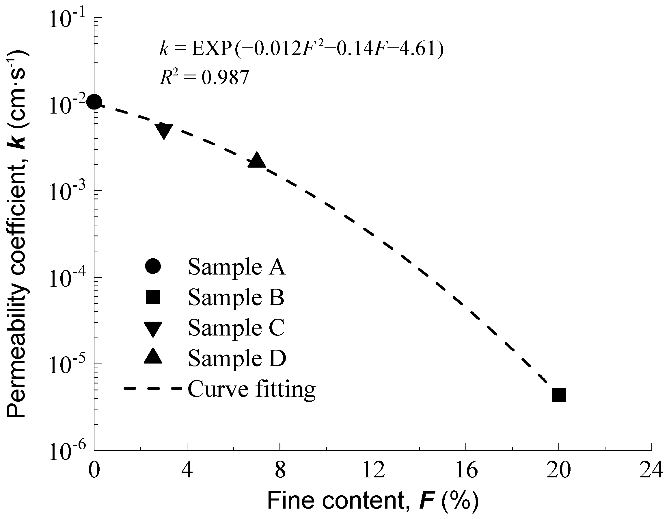
Based on
Figure 10, the permeability coefficient of the graded gravel with zero fine content is estimated to be
k = 9.98 × 10
−2 mm/s. If the graded gravel under the shoulder capping layer is replaced with the composite drainage board, the minimum replacement depth
da,min calculated from Equation (20b) is 42 mm. Simultaneously, according to Equations (22) and (23), the permeability coefficient
kg of the blind ditch material under the cable trough should be greater than 23 mm/s, and the overlap length
Lg should be greater than 13 mm. Based on the lab permeability test data [
28] of coarse-grained soil, uniformly graded gravel material can be selected for the construction of the blind ditch [
29,
30,
31,
32,
33].
The permeability coefficient
kg > 23 mm/s for the blind ditch material [
34] is derived from laboratory-tested coarse-grained soils [
28], ensuring compatibility with the graded gravel’s hydraulic conductivity. This alignment guarantees uninterrupted drainage continuity, which is critical for mitigating ponding in high-infiltration scenarios.


